EP3680454B1 - Puffersystem für einen gasturbinenmotor - Google Patents
Puffersystem für einen gasturbinenmotor Download PDFInfo
- Publication number
- EP3680454B1 EP3680454B1 EP20150805.8A EP20150805A EP3680454B1 EP 3680454 B1 EP3680454 B1 EP 3680454B1 EP 20150805 A EP20150805 A EP 20150805A EP 3680454 B1 EP3680454 B1 EP 3680454B1
- Authority
- EP
- European Patent Office
- Prior art keywords
- air
- seal
- shaft
- gas turbine
- turbine engine
- Prior art date
- Legal status (The legal status is an assumption and is not a legal conclusion. Google has not performed a legal analysis and makes no representation as to the accuracy of the status listed.)
- Active
Links
Images


Classifications
-
- F—MECHANICAL ENGINEERING; LIGHTING; HEATING; WEAPONS; BLASTING
- F01—MACHINES OR ENGINES IN GENERAL; ENGINE PLANTS IN GENERAL; STEAM ENGINES
- F01D—NON-POSITIVE DISPLACEMENT MACHINES OR ENGINES, e.g. STEAM TURBINES
- F01D25/00—Component parts, details, or accessories, not provided for in, or of interest apart from, other groups
- F01D25/18—Lubricating arrangements
- F01D25/183—Sealing means
-
- F—MECHANICAL ENGINEERING; LIGHTING; HEATING; WEAPONS; BLASTING
- F01—MACHINES OR ENGINES IN GENERAL; ENGINE PLANTS IN GENERAL; STEAM ENGINES
- F01D—NON-POSITIVE DISPLACEMENT MACHINES OR ENGINES, e.g. STEAM TURBINES
- F01D11/00—Preventing or minimising internal leakage of working-fluid, e.g. between stages
- F01D11/02—Preventing or minimising internal leakage of working-fluid, e.g. between stages by non-contact sealings, e.g. of labyrinth type
- F01D11/04—Preventing or minimising internal leakage of working-fluid, e.g. between stages by non-contact sealings, e.g. of labyrinth type using sealing fluid, e.g. steam
-
- F—MECHANICAL ENGINEERING; LIGHTING; HEATING; WEAPONS; BLASTING
- F01—MACHINES OR ENGINES IN GENERAL; ENGINE PLANTS IN GENERAL; STEAM ENGINES
- F01D—NON-POSITIVE DISPLACEMENT MACHINES OR ENGINES, e.g. STEAM TURBINES
- F01D11/00—Preventing or minimising internal leakage of working-fluid, e.g. between stages
- F01D11/02—Preventing or minimising internal leakage of working-fluid, e.g. between stages by non-contact sealings, e.g. of labyrinth type
- F01D11/04—Preventing or minimising internal leakage of working-fluid, e.g. between stages by non-contact sealings, e.g. of labyrinth type using sealing fluid, e.g. steam
- F01D11/06—Control thereof
-
- F—MECHANICAL ENGINEERING; LIGHTING; HEATING; WEAPONS; BLASTING
- F01—MACHINES OR ENGINES IN GENERAL; ENGINE PLANTS IN GENERAL; STEAM ENGINES
- F01D—NON-POSITIVE DISPLACEMENT MACHINES OR ENGINES, e.g. STEAM TURBINES
- F01D25/00—Component parts, details, or accessories, not provided for in, or of interest apart from, other groups
- F01D25/16—Arrangement of bearings; Supporting or mounting bearings in casings
-
- F—MECHANICAL ENGINEERING; LIGHTING; HEATING; WEAPONS; BLASTING
- F01—MACHINES OR ENGINES IN GENERAL; ENGINE PLANTS IN GENERAL; STEAM ENGINES
- F01D—NON-POSITIVE DISPLACEMENT MACHINES OR ENGINES, e.g. STEAM TURBINES
- F01D25/00—Component parts, details, or accessories, not provided for in, or of interest apart from, other groups
- F01D25/16—Arrangement of bearings; Supporting or mounting bearings in casings
- F01D25/162—Bearing supports
-
- F—MECHANICAL ENGINEERING; LIGHTING; HEATING; WEAPONS; BLASTING
- F05—INDEXING SCHEMES RELATING TO ENGINES OR PUMPS IN VARIOUS SUBCLASSES OF CLASSES F01-F04
- F05D—INDEXING SCHEME FOR ASPECTS RELATING TO NON-POSITIVE-DISPLACEMENT MACHINES OR ENGINES, GAS-TURBINES OR JET-PROPULSION PLANTS
- F05D2240/00—Components
- F05D2240/50—Bearings
-
- F—MECHANICAL ENGINEERING; LIGHTING; HEATING; WEAPONS; BLASTING
- F05—INDEXING SCHEMES RELATING TO ENGINES OR PUMPS IN VARIOUS SUBCLASSES OF CLASSES F01-F04
- F05D—INDEXING SCHEME FOR ASPECTS RELATING TO NON-POSITIVE-DISPLACEMENT MACHINES OR ENGINES, GAS-TURBINES OR JET-PROPULSION PLANTS
- F05D2240/00—Components
- F05D2240/55—Seals
-
- F—MECHANICAL ENGINEERING; LIGHTING; HEATING; WEAPONS; BLASTING
- F05—INDEXING SCHEMES RELATING TO ENGINES OR PUMPS IN VARIOUS SUBCLASSES OF CLASSES F01-F04
- F05D—INDEXING SCHEME FOR ASPECTS RELATING TO NON-POSITIVE-DISPLACEMENT MACHINES OR ENGINES, GAS-TURBINES OR JET-PROPULSION PLANTS
- F05D2260/00—Function
- F05D2260/98—Lubrication
Definitions
- a gas turbine engine typically includes a fan section, a compressor section, a combustor section, and a turbine section. Air entering the compressor section is compressed and delivered into the combustor section where it is mixed with fuel and ignited to generate a high-speed exhaust gas flow. The high-speed exhaust gas flow expands through the turbine section to drive the compressor and the fan section.
- the compressor section typically includes low and high pressure compressors, and the turbine section includes low and high pressure turbines.
- a gas turbine engine also includes bearings that support rotatable shafts.
- the bearings require lubricant.
- Various seals may be utilized near the rotating shafts of the engine, such as to contain oil within oil fed areas of the engine including bearing compartments.
- a pressure outside of a bearing compartment that contains the bearings is typically maintained at a higher pressure than the pressure within the bearing compartment to assist in retaining the lubricant within the bearing compartment.
- EP 3 388 636 A1 discloses a gas turbine engine according to the preamble of claim 1.
- EP 3 396 119 A1 discloses an intershaft compartment buffering arrangement.
- the present invention provides a gas turbine engine as set forth in claim 1. Embodiments of the disclosure are set forth in the dependent claims.
- FIG. 1 schematically illustrates a gas turbine engine 20.
- the gas turbine engine 20 is disclosed herein as a two-spool turbofan that generally incorporates a fan section 22, a compressor section 24, a combustor section 26 and a turbine section 28.
- the fan section 22 drives air along a bypass flow path B in a bypass duct defined within a nacelle 15, and also drives air along a core flow path C for compression and communication into the combustor section 26 then expansion through the turbine section 28.
- FIG. 1 schematically illustrates a gas turbine engine 20.
- the gas turbine engine 20 is disclosed herein as a two-spool turbofan that generally incorporates a fan section 22, a compressor section 24, a combustor section 26 and a turbine section 28.
- the fan section 22 drives air along a bypass flow path B in a bypass duct defined within a nacelle 15, and also drives air along a core flow path C for compression and communication into the combustor section 26 then expansion through the turbine section 28.
- FIG. 1 schematic
- the exemplary engine 20 generally includes a low speed spool 30 and a high speed spool 32 mounted for rotation about an engine central longitudinal axis A relative to an engine static structure 36 via several bearing systems 38. It should be understood that various bearing systems 38 at various locations may alternatively or additionally be provided, and the location of bearing systems 38 may be varied as appropriate to the application.
- the low speed spool 30 generally includes an inner shaft 40 that interconnects, a first (or low) pressure compressor 44 and a first (or low) pressure turbine 46.
- the inner shaft 40 is connected to the fan 42 through a speed change mechanism, which in exemplary gas turbine engine 20 is illustrated as a geared architecture 48 to drive a fan 42 at a lower speed than the low speed spool 30.
- the high speed spool 32 includes an outer shaft 50 that interconnects a second (or high) pressure compressor 52 and a second (or high) pressure turbine 54.
- a combustor 56 is arranged in exemplary gas turbine 20 between the high pressure compressor 52 and the high pressure turbine 54.
- a mid-turbine frame 57 of the engine static structure 36 may be arranged generally between the high pressure turbine 54 and the low pressure turbine 46.
- the mid-turbine frame 57 further supports bearing systems 38 in the turbine section 28.
- the inner shaft 40 and the outer shaft 50 are concentric and rotate via bearing systems 38 about the engine central longitudinal axis A which is colline
- the core airflow is compressed by the low pressure compressor 44 then the high pressure compressor 52, mixed and burned with fuel in the combustor 56, then expanded over the high pressure turbine 54 and low pressure turbine 46.
- the mid-turbine frame 57 includes airfoils 59 which are in the core airflow path C.
- the turbines 46, 54 rotationally drive the respective low speed spool 30 and high speed spool 32 in response to the expansion.
- gear system 48 may be located aft of the low pressure compressor, or aft of the combustor section 26 or even aft of turbine section 28, and fan 42 may be positioned forward or aft of the location of gear system 48.
- the engine 20 in one example is a high-bypass geared aircraft engine.
- the engine 20 bypass ratio is greater than about six, with an example embodiment being greater than about ten
- the geared architecture 48 is an epicyclic gear train, such as a planetary gear system or other gear system, with a gear reduction ratio of greater than about 2.3 and the low pressure turbine 46 has a pressure ratio that is greater than about five.
- the engine 20 bypass ratio is greater than about ten
- the fan diameter is significantly larger than that of the low pressure compressor 44
- the low pressure turbine 46 has a pressure ratio that is greater than about five.
- Low pressure turbine 46 pressure ratio is pressure measured prior to inlet of low pressure turbine 46 as related to the pressure at the outlet of the low pressure turbine 46 prior to an exhaust nozzle.
- the geared architecture 48 may be an epicycle gear train, such as a planetary gear system or other gear system, with a gear reduction ratio of greater than about 2.3:1 and less than about 5:1. It should be understood, however, that the above parameters are only exemplary of one embodiment of a geared architecture engine and that the present invention is applicable to other gas turbine engines including direct drive turbofans, low bypass engines, and multi-stage fan engines.
- the fan section 22 of the engine 20 is designed for a particular flight condition -- typically cruise at about 0.8 Mach and about 35,000 feet (10,668 meters).
- the flight condition of 0.8 Mach and 35,000 ft (10,668 meters), with the engine at its best fuel consumption - also known as "bucket cruise Thrust Specific Fuel Consumption ('TSFC')" - is the industry standard parameter of lbm of fuel being burned divided by lbf of thrust the engine produces at that minimum point.
- "Low fan pressure ratio” is the pressure ratio across the fan blade alone, without a Fan Exit Guide Vane (“FEGV”) system.
- the low fan pressure ratio as disclosed herein according to one non-limiting embodiment is less than about 1.45.
- the "Low corrected fan tip speed” as disclosed herein according to one non-limiting embodiment is less than about 1150 ft / second (350.5 meters/second).
- the engine 20 includes a buffer system 200, which is illustrated schematically in Figure 2 .
- the buffer system 200 is illustrated with respect to the engine central longitudinal axis A.
- the buffer system 200 is shown as part of a two-spool configuration that includes the inner shaft 40 and the outer shaft 50.
- the inner and outer shafts 40, 50 are rotatably supported by a plurality of bearings contained within a bearing compartment 224. While a two-spool configuration is shown, the invention is not limited to two-spool configurations.
- the buffer system 200 could be used in three-spool configurations, for example.
- FIG 2 various locations of the engine 20 are denoted by letters A, B, C, and D. At each of these locations A-D, a pair of seals are shown. Each pair of seals includes an air seal and an oil seal. The seals are used in the buffer system 200 to isolate a fluid from one or more regions of the engine 20. In particular, the seals are used to retain lubricating fluid (i.e., oil) within the bearing compartment 224.
- lubricating fluid i.e., oil
- an air seal 230a and an oil seal 234a are shown. Each of the seals comprises a radially interior side/surface and radially outer side/surface. At location B, an air seal 230b and an oil seal 234b are shown. At location C, an air seal 230c and an oil seal 234c are shown. At location D, yet another air seal 230d and oil seal 234d are shown.
- Each of the seals can be provided by circumferentially segmented seals extending circumferentially about the engine central longitudinal axis A.
- each of the air seals 230a-230d are provided by the same type of seal, and the oil seals 234a-234d are also provided by the same type of seal, albeit a different type than the air seals 230a-230d.
- the seals 230a and 234a are used to seal the bearing compartment 224 with respect to the inner shaft 40.
- the seals 230d and 234d are used to seal the bearing compartment 224 with respect to the outer shaft 50.
- the seals 230b, 234b, 230c, and 234c are also used to seal the bearing compartment 224 with respect to the inner and outer shafts 40, 50, but in particular these seals are used to provide sealing between the inner and outer shafts 40, 50, in an intershaft region 240 where the inner and outer shafts 40, 50 interact with or surround one another.
- There is a gap between the inner and outer shafts 40, 50 i.e., the inner and outer shafts 40, 50 are axially spaced-apart from one another) through which fluid may flow.
- a radially outer side (the term "radially” refers to a direction normal to the engine central longitudinal axis A) of air seal 230b may be fixed to a radially inner surface of the bearing compartment 224, and a radially inner surface of the air seal 230b interfaces with the inner shaft 40.
- Air flow such as leakage flow, over the air seal 230b, and specifically between the radially inner surface of the air seal 230b and the inner shaft 40, establishes a seal between the air seal 230b and the inner shaft 40.
- the radially outer surface of the oil seal 234b may likewise be fixed to the radially inner surface of the bearing compartment 224, and air is configured to flow between the radially inner surface of the oil seal 234b and the inner shaft 40.
- the air seal 230c and oil seal 234c are arranged in substantially the same way, except they are provided on an axially opposite side of an intershaft region 240 and are configured to seal relative to the outer shaft 50 as opposed to the inner shaft 40.
- a buffer source provides air to each pair of air seals and oil seals at the respective locations A-D.
- the buffer source may originate from one or more stages of the low pressure compressor 40, such as for example an axially aft-most stage of the low pressure compressor.
- the buffer source originates from the high pressure compressor 52, which provides air at a greater pressure than the air pressure associated with the low pressure compressor 40.
- the buffer source of air is represented in the box labeled "HPC,” which stands for high pressure compressor 52, in Figure 2 .
- air 242 flows from the buffer source, which again is the high pressure compressor 52, to the intershaft region 240.
- a portion of the air 242 flows over the air seals 230b and 230c, while another, reduced-pressure portion is directed downstream of the air seals 230b, 230c and flows across the oil seals 234b, 234c.
- any remaining air flows to locations A and D, as generally shown in Figure 2 .
- excess air might be directed to other low pressure sink locations, including overboard bleeds, the core compartment, or locations along the main gas path.
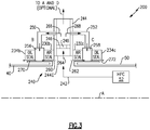
- Figure 3 illustrates the detail of the buffer system 200 in the intershaft region 240.
- the The buffer system 200 includes a buffer manifold 244 in the intershaft region 240.
- An inlet 2441 to the buffer manifold 244 is downstream of, and radially outward of, the interfaces between the air seals 230b, 230c and the respective inner and outer shafts 40, 50.
- the buffer manifold 244 may be provided by a tube or arranged as a plenum. In general, the buffer manifold 244 projects in a radial direction normal to the engine central longitudinal axis A.
- the buffer manifold 244 includes an orifice plate 246, which is a relatively thin plate mounted inside the wall(s) of the buffer manifold 244, and which has an orifice 248.
- the orifice 248 is smaller in diameter than the remainder of the buffer manifold 244.
- first and second tubes 250, 252 fluidly couple the buffer manifold 244 to locations between the air seals 230b, 230c and the respective oil seals 234b, 234c.
- first tube 250 is fluidly coupled between the buffer manifold 244 and a first plenum 256 arranged axially between the air seal 230b and the oil seal 234b.
- second tube 252 is fluidly coupled between the buffer manifold 244 and a second plenum 258 arranged axially between the air seal 230b and the oil seal 234b.
- the inlets to the first and second tubes 250, 252 are downstream of the orifice plate 246, and thus the first and second tubes 250, 252 are supplied with reduced-pressure air flows.
- the first and second tubes 250, 252 are configured to direct flow from the buffer manifold 244 in an axial direction parallel to the engine central longitudinal axis A, and to then turn that flow in a radial direction toward the engine central longitudinal axis A and ultimately to the first and second plenums 256, 258.
- the air that has flowed over the air seals 230b, 230c is combined with the air from downstream of the orifice plate 246, and the combined flows flow over the respective oil seals 234b, 234c.
- air 242 from the buffer source is directed to the intershaft region 240.
- a first portion of the air 242 splits into airflows 260, 262 and flows over respective air seals 230b, 230c.
- the airflow 260 flows between the air seal 230b and the inner shaft 40
- the airflow 262 flows between the air seal 230c and the outer shaft 50.
- a second portion 264 of the air 242 which is a portion of the air 242 that did not flow over the seals 230b, 230c (i.e., air 242 less airflows 260, 262), enters the buffer manifold 244 and flows through the orifice 248. As such, the second portion 264 exhibits a reduced pressure downstream of the orifice 248. Some or all of the second portion 264 becomes airflows 266, 268 in the first and second tubes 250, 252, respectively.
- the buffer manifold 244 has a closed end and causes all of the second portion 264 to essentially split into the airflows 266, 268.
- the buffer manifold 244 is fluidly coupled to the downstream locations A and D, and thus some of the second portion 264 does not enter the first and second tubes 250, 252, and instead continues downstream toward the locations A and/or D.
- the airflow 266 intermixes with the airflow 260 within the first plenum 256.
- the pressure of the airflow 260 is reduced relative to that of the air 242 by virtue of the air seal 230b.
- the combined airflow 270 flows over the oil seal 234b and into the bearing compartment 224.
- the airflow 268 intermixes with the airflow 262 within the second plenum 258, and the combined airflow 272 flows over the oil seal 234c and into the bearing compartment 224.
- the buffer system 200 allows the oil seals 234b, 234c to operate efficiently while also prolonging the life of the air seals 230b, 230c. Further, as the air seals 230b, 230c degrade over time, increased leakage over the air seals 230b, 230c will replace the flow through the first and second tubes 250, 252, and will only cause a minor change in the pressure of the airflow over the oil seals 234b, 234c, which ensures consistent pressurization of the oil seals 234b, 234c.
Landscapes
- Engineering & Computer Science (AREA)
- Mechanical Engineering (AREA)
- General Engineering & Computer Science (AREA)
- Sealing Using Fluids, Sealing Without Contact, And Removal Of Oil (AREA)
- Structures Of Non-Positive Displacement Pumps (AREA)
Claims (6)
- Gasturbinentriebwerk (20), umfassend:einen Hochdruckverdichter (52), welcher dazu konfiguriert ist, einen Luftstrom (242) an einen Zwischenwellenbereich (240) zwischen einer ersten Welle (40) und einer zweiten Welle (50) bereitzustellen, welche konzentrisch zu der ersten Welle (40) ist;eine Lagerkammer (224);eine erste Luftdichtung (230b), welche dazu konfiguriert ist, zwischen der ersten Welle (40) und der Lagerkammer (224) abzudichten;eine erste Öldichtung (234b), welche dazu konfiguriert ist, zwischen der ersten Welle (40) und der Lagerkammer (224) abzudichten;eine zweite Luftdichtung (230c), welche dazu konfiguriert ist, zwischen der zweiten Welle (50) und der Lagerkammer (224) abzudichten;eine zweite Öldichtung (234c), welche dazu konfiguriert ist, zwischen der zweiten Welle (50) und der Lagerkammer (224) abzudichten; undeinen Pufferkrümmer (244) in dem Zwischenwellenbereich (240),dadurch gekennzeichnet, dass:ein erster Teil (260, 262) des Luftstroms (242) von dem Hochdruckverdichter (52) über die erste und zweite Luftdichtung (230b, 230c) strömt und ein zweiter Teil (264) des Luftstroms (242) von dem Hochdruckverdichter (52) durch den Pufferkrümmer (244) strömt, wobei der Pufferkrümmer (244) mit einem ersten Rohr (250) und einem zweiten Rohr (252) fluidverbunden ist, das erste Rohr (250) zwischen dem Pufferkrümmer (244) und einem Ort zwischen der ersten Luftdichtung (230b) und der ersten Öldichtung (234b) fluidverbunden ist, und das zweite Rohr (252) zwischen dem Pufferkrümmer (244) und einem Ort zwischen der zweiten Luftdichtung (230c) und der zweiten Öldichtung (234c) fluidverbunden ist, der Pufferkrümmer (244) eine Messblende (246) beinhaltet, welche eine Blende (248) aufweist, der zweite Teil (264) des Luftstroms von dem Hochdruckverdichter (52) durch die Blende (248) strömt, und Einlässe des ersten und zweiten Rohrs (250, 252) stromabwärts von der Messblende (246) liegen; unddadurch, dass das Gasturbinentriebwerk (20) ferner ein erstes Plenum (256) zwischen der ersten Luftdichtung (230b) und der ersten Öldichtung (234b) und ein zweites Plenum (258) zwischen der zweiten Luftdichtung (230c) und der zweiten Öldichtung (234c) umfasst, wobei das erste Rohr (250) mit dem ersten Plenum (256) fluidverbunden ist und das zweite Rohr (252) mit dem zweiten Plenum (258) fluidverbunden ist, so dass die Luft, welche über die erste Luftdichtung (230b) geströmt ist, in dem ersten Plenum (256) mit der Luft aus dem ersten Rohr (250) kombiniert wird, und der kombinierte Strom über die erste Öldichtung (234b) strömt, so dass die Luft, welche über die zweite Luftdichtung (230c) geströmt ist, in dem zweiten Plenum (258) mit der Luft aus dem zweiten Rohr (255) kombiniert wird und der kombinierte Strom über die zweite Öldichtung (234c) strömt.
- Gasturbinentriebwerk nach Anspruch 1, wobei ein Einlass (244I) zu dem Pufferkrümmer (244) radial außerhalb einer Schnittstelle zwischen der ersten Luftdichtung (230b) und der ersten Welle (40) liegt, und radial außerhalb einer Schnittstelle zwischen der zweiten Luftdichtung (230c) und der zweiten Welle (50).
- Gasturbinentriebwerk nach Anspruch 1 oder 2, wobei die erste und zweite Welle (40, 50) durch eine Vielzahl von Lagern drehend getragen werden, welche in der Lagerkammer (224) enthalten sind.
- Gasturbinentriebwerk nach einem der vorstehenden Ansprüche, wobei die erste Welle (40) einen Niederdruckverdichter (40) und eine Niederdruckturbine (46) miteinander verbindet, und die zweite Welle (50) den Hochdruckkompressor (52) und eine Hochdruckturbine (54) miteinander verbindet.
- Gasturbinentriebwerk nach einem der vorstehenden Ansprüche, wobei der Pufferkrümmer (244) dazu konfiguriert ist, den Druck des Luftstroms (242) von dem Hochdruckverdichter (52) zu reduzieren.
- Gasturbinentriebwerk nach einem der vorstehenden Ansprüche, wobei die Blende (248) derart bemessen ist, dass der zweite Teil (264) des Stroms von dem Hochdruckverdichter (52) einen reduzierten Druck stromabwärts von der Blende (248) aufweist.
Applications Claiming Priority (1)
| Application Number | Priority Date | Filing Date | Title |
|---|---|---|---|
| US16/242,345 US10837318B2 (en) | 2019-01-08 | 2019-01-08 | Buffer system for gas turbine engine |
Publications (2)
| Publication Number | Publication Date |
|---|---|
| EP3680454A1 EP3680454A1 (de) | 2020-07-15 |
| EP3680454B1 true EP3680454B1 (de) | 2021-10-27 |
Family
ID=69156230
Family Applications (1)
| Application Number | Title | Priority Date | Filing Date |
|---|---|---|---|
| EP20150805.8A Active EP3680454B1 (de) | 2019-01-08 | 2020-01-08 | Puffersystem für einen gasturbinenmotor |
Country Status (2)
| Country | Link |
|---|---|
| US (1) | US10837318B2 (de) |
| EP (1) | EP3680454B1 (de) |
Families Citing this family (1)
| Publication number | Priority date | Publication date | Assignee | Title |
|---|---|---|---|---|
| US11572837B2 (en) | 2021-01-22 | 2023-02-07 | Pratt & Whitney Canada Corp. | Buffer fluid delivery system and method for a shaft seal of a gas turbine engine |
Family Cites Families (14)
| Publication number | Priority date | Publication date | Assignee | Title |
|---|---|---|---|---|
| US4561246A (en) * | 1983-12-23 | 1985-12-31 | United Technologies Corporation | Bearing compartment for a gas turbine engine |
| US4645415A (en) * | 1983-12-23 | 1987-02-24 | United Technologies Corporation | Air cooler for providing buffer air to a bearing compartment |
| US6470666B1 (en) * | 2001-04-30 | 2002-10-29 | General Electric Company | Methods and systems for preventing gas turbine engine lube oil leakage |
| US7287384B2 (en) * | 2004-12-13 | 2007-10-30 | Pratt & Whitney Canada Corp. | Bearing chamber pressurization system |
| US7591631B2 (en) * | 2006-06-30 | 2009-09-22 | United Technologies Corporation | Flow delivery system for seals |
| GB2495092B (en) * | 2011-09-28 | 2014-01-01 | Rolls Royce Plc | Sealing arrangement |
| US8366382B1 (en) | 2012-01-31 | 2013-02-05 | United Technologies Corporation | Mid-turbine frame buffer system |
| JP2016528436A (ja) * | 2013-08-16 | 2016-09-15 | ゼネラル・エレクトリック・カンパニイ | 流れ渦スポイラ |
| FR3018109B1 (fr) * | 2014-02-28 | 2016-05-06 | Snecma | Reduction du debit de fuite d'un joint a brosse par obstruction geometrique flexible |
| US20180094543A1 (en) * | 2016-10-03 | 2018-04-05 | General Electric Company | Insert apparatus and system for oil nozzle boundary layer injection |
| US10520035B2 (en) | 2016-11-04 | 2019-12-31 | United Technologies Corporation | Variable volume bearing compartment |
| US10161314B2 (en) | 2017-04-11 | 2018-12-25 | United Technologies Corporation | Vented buffer air supply for intershaft seals |
| US10513938B2 (en) | 2017-04-25 | 2019-12-24 | United Technologies Corporation | Intershaft compartment buffering arrangement |
| US10927845B2 (en) * | 2017-05-24 | 2021-02-23 | The Boeing Company | Seal assembly and method for reducing aircraft engine oil leakage |
-
2019
- 2019-01-08 US US16/242,345 patent/US10837318B2/en active Active
-
2020
- 2020-01-08 EP EP20150805.8A patent/EP3680454B1/de active Active
Also Published As
| Publication number | Publication date |
|---|---|
| EP3680454A1 (de) | 2020-07-15 |
| US10837318B2 (en) | 2020-11-17 |
| US20200217220A1 (en) | 2020-07-09 |
Similar Documents
| Publication | Publication Date | Title |
|---|---|---|
| US11927138B2 (en) | Fan drive gear system | |
| US10151240B2 (en) | Mid-turbine frame buffer system | |
| US11092025B2 (en) | Gas turbine engine with dove-tailed TOBI vane | |
| US9574459B2 (en) | Non-contacting seals for geared gas turbine engine bearing compartments | |
| US10605352B2 (en) | Transfer bearing for geared turbofan | |
| US11988146B2 (en) | Thermal management of a gas turbine engine shaft | |
| US10746049B2 (en) | Gas turbine engine case including bearing compartment | |
| EP3719268A1 (de) | Dichtungskanal mit deflektor und fänger für gasturbinenmotor | |
| US11421553B2 (en) | Dual radial scoop oil delivery system | |
| EP2955332B1 (de) | Getriebedichtung eines gasturbinenmotors mit getriebe-fan | |
| EP3680454A1 (de) | Puffersystem für einen gasturbinenmotor | |
| EP4074952B1 (de) | Getriebegasturbine mit ölabsaugungspumpenunterstützung | |
| EP3812555B1 (de) | Ölrückflussanordnung für ein gasturbinentriebwerk |
Legal Events
| Date | Code | Title | Description |
|---|---|---|---|
| PUAI | Public reference made under article 153(3) epc to a published international application that has entered the european phase |
Free format text: ORIGINAL CODE: 0009012 |
|
| STAA | Information on the status of an ep patent application or granted ep patent |
Free format text: STATUS: THE APPLICATION HAS BEEN PUBLISHED |
|
| AK | Designated contracting states |
Kind code of ref document: A1 Designated state(s): AL AT BE BG CH CY CZ DE DK EE ES FI FR GB GR HR HU IE IS IT LI LT LU LV MC MK MT NL NO PL PT RO RS SE SI SK SM TR |
|
| AX | Request for extension of the european patent |
Extension state: BA ME |
|
| STAA | Information on the status of an ep patent application or granted ep patent |
Free format text: STATUS: REQUEST FOR EXAMINATION WAS MADE |
|
| 17P | Request for examination filed |
Effective date: 20210115 |
|
| RBV | Designated contracting states (corrected) |
Designated state(s): AL AT BE BG CH CY CZ DE DK EE ES FI FR GB GR HR HU IE IS IT LI LT LU LV MC MK MT NL NO PL PT RO RS SE SI SK SM TR |
|
| RAP1 | Party data changed (applicant data changed or rights of an application transferred) |
Owner name: RAYTHEON TECHNOLOGIES CORPORATION |
|
| GRAP | Despatch of communication of intention to grant a patent |
Free format text: ORIGINAL CODE: EPIDOSNIGR1 |
|
| STAA | Information on the status of an ep patent application or granted ep patent |
Free format text: STATUS: GRANT OF PATENT IS INTENDED |
|
| INTG | Intention to grant announced |
Effective date: 20210512 |
|
| GRAS | Grant fee paid |
Free format text: ORIGINAL CODE: EPIDOSNIGR3 |
|
| GRAA | (expected) grant |
Free format text: ORIGINAL CODE: 0009210 |
|
| STAA | Information on the status of an ep patent application or granted ep patent |
Free format text: STATUS: THE PATENT HAS BEEN GRANTED |
|
| AK | Designated contracting states |
Kind code of ref document: B1 Designated state(s): AL AT BE BG CH CY CZ DE DK EE ES FI FR GB GR HR HU IE IS IT LI LT LU LV MC MK MT NL NO PL PT RO RS SE SI SK SM TR |
|
| REG | Reference to a national code |
Ref country code: GB Ref legal event code: FG4D |
|
| REG | Reference to a national code |
Ref country code: CH Ref legal event code: EP |
|
| REG | Reference to a national code |
Ref country code: DE Ref legal event code: R096 Ref document number: 602020000798 Country of ref document: DE |
|
| REG | Reference to a national code |
Ref country code: AT Ref legal event code: REF Ref document number: 1441971 Country of ref document: AT Kind code of ref document: T Effective date: 20211115 |
|
| REG | Reference to a national code |
Ref country code: IE Ref legal event code: FG4D |
|
| REG | Reference to a national code |
Ref country code: LT Ref legal event code: MG9D |
|
| REG | Reference to a national code |
Ref country code: NL Ref legal event code: MP Effective date: 20211027 |
|
| REG | Reference to a national code |
Ref country code: AT Ref legal event code: MK05 Ref document number: 1441971 Country of ref document: AT Kind code of ref document: T Effective date: 20211027 |
|
| PG25 | Lapsed in a contracting state [announced via postgrant information from national office to epo] |
Ref country code: RS Free format text: LAPSE BECAUSE OF FAILURE TO SUBMIT A TRANSLATION OF THE DESCRIPTION OR TO PAY THE FEE WITHIN THE PRESCRIBED TIME-LIMIT Effective date: 20211027 Ref country code: LT Free format text: LAPSE BECAUSE OF FAILURE TO SUBMIT A TRANSLATION OF THE DESCRIPTION OR TO PAY THE FEE WITHIN THE PRESCRIBED TIME-LIMIT Effective date: 20211027 Ref country code: FI Free format text: LAPSE BECAUSE OF FAILURE TO SUBMIT A TRANSLATION OF THE DESCRIPTION OR TO PAY THE FEE WITHIN THE PRESCRIBED TIME-LIMIT Effective date: 20211027 Ref country code: BG Free format text: LAPSE BECAUSE OF FAILURE TO SUBMIT A TRANSLATION OF THE DESCRIPTION OR TO PAY THE FEE WITHIN THE PRESCRIBED TIME-LIMIT Effective date: 20220127 Ref country code: AT Free format text: LAPSE BECAUSE OF FAILURE TO SUBMIT A TRANSLATION OF THE DESCRIPTION OR TO PAY THE FEE WITHIN THE PRESCRIBED TIME-LIMIT Effective date: 20211027 |
|
| PG25 | Lapsed in a contracting state [announced via postgrant information from national office to epo] |
Ref country code: IS Free format text: LAPSE BECAUSE OF FAILURE TO SUBMIT A TRANSLATION OF THE DESCRIPTION OR TO PAY THE FEE WITHIN THE PRESCRIBED TIME-LIMIT Effective date: 20220227 Ref country code: SE Free format text: LAPSE BECAUSE OF FAILURE TO SUBMIT A TRANSLATION OF THE DESCRIPTION OR TO PAY THE FEE WITHIN THE PRESCRIBED TIME-LIMIT Effective date: 20211027 Ref country code: PT Free format text: LAPSE BECAUSE OF FAILURE TO SUBMIT A TRANSLATION OF THE DESCRIPTION OR TO PAY THE FEE WITHIN THE PRESCRIBED TIME-LIMIT Effective date: 20220228 Ref country code: PL Free format text: LAPSE BECAUSE OF FAILURE TO SUBMIT A TRANSLATION OF THE DESCRIPTION OR TO PAY THE FEE WITHIN THE PRESCRIBED TIME-LIMIT Effective date: 20211027 Ref country code: NO Free format text: LAPSE BECAUSE OF FAILURE TO SUBMIT A TRANSLATION OF THE DESCRIPTION OR TO PAY THE FEE WITHIN THE PRESCRIBED TIME-LIMIT Effective date: 20220127 Ref country code: NL Free format text: LAPSE BECAUSE OF FAILURE TO SUBMIT A TRANSLATION OF THE DESCRIPTION OR TO PAY THE FEE WITHIN THE PRESCRIBED TIME-LIMIT Effective date: 20211027 Ref country code: LV Free format text: LAPSE BECAUSE OF FAILURE TO SUBMIT A TRANSLATION OF THE DESCRIPTION OR TO PAY THE FEE WITHIN THE PRESCRIBED TIME-LIMIT Effective date: 20211027 Ref country code: HR Free format text: LAPSE BECAUSE OF FAILURE TO SUBMIT A TRANSLATION OF THE DESCRIPTION OR TO PAY THE FEE WITHIN THE PRESCRIBED TIME-LIMIT Effective date: 20211027 Ref country code: GR Free format text: LAPSE BECAUSE OF FAILURE TO SUBMIT A TRANSLATION OF THE DESCRIPTION OR TO PAY THE FEE WITHIN THE PRESCRIBED TIME-LIMIT Effective date: 20220128 Ref country code: ES Free format text: LAPSE BECAUSE OF FAILURE TO SUBMIT A TRANSLATION OF THE DESCRIPTION OR TO PAY THE FEE WITHIN THE PRESCRIBED TIME-LIMIT Effective date: 20211027 |
|
| REG | Reference to a national code |
Ref country code: DE Ref legal event code: R097 Ref document number: 602020000798 Country of ref document: DE |
|
| PG25 | Lapsed in a contracting state [announced via postgrant information from national office to epo] |
Ref country code: SM Free format text: LAPSE BECAUSE OF FAILURE TO SUBMIT A TRANSLATION OF THE DESCRIPTION OR TO PAY THE FEE WITHIN THE PRESCRIBED TIME-LIMIT Effective date: 20211027 Ref country code: SK Free format text: LAPSE BECAUSE OF FAILURE TO SUBMIT A TRANSLATION OF THE DESCRIPTION OR TO PAY THE FEE WITHIN THE PRESCRIBED TIME-LIMIT Effective date: 20211027 Ref country code: RO Free format text: LAPSE BECAUSE OF FAILURE TO SUBMIT A TRANSLATION OF THE DESCRIPTION OR TO PAY THE FEE WITHIN THE PRESCRIBED TIME-LIMIT Effective date: 20211027 Ref country code: EE Free format text: LAPSE BECAUSE OF FAILURE TO SUBMIT A TRANSLATION OF THE DESCRIPTION OR TO PAY THE FEE WITHIN THE PRESCRIBED TIME-LIMIT Effective date: 20211027 Ref country code: DK Free format text: LAPSE BECAUSE OF FAILURE TO SUBMIT A TRANSLATION OF THE DESCRIPTION OR TO PAY THE FEE WITHIN THE PRESCRIBED TIME-LIMIT Effective date: 20211027 Ref country code: CZ Free format text: LAPSE BECAUSE OF FAILURE TO SUBMIT A TRANSLATION OF THE DESCRIPTION OR TO PAY THE FEE WITHIN THE PRESCRIBED TIME-LIMIT Effective date: 20211027 |
|
| PG25 | Lapsed in a contracting state [announced via postgrant information from national office to epo] |
Ref country code: MC Free format text: LAPSE BECAUSE OF FAILURE TO SUBMIT A TRANSLATION OF THE DESCRIPTION OR TO PAY THE FEE WITHIN THE PRESCRIBED TIME-LIMIT Effective date: 20211027 |
|
| PLBE | No opposition filed within time limit |
Free format text: ORIGINAL CODE: 0009261 |
|
| STAA | Information on the status of an ep patent application or granted ep patent |
Free format text: STATUS: NO OPPOSITION FILED WITHIN TIME LIMIT |
|
| REG | Reference to a national code |
Ref country code: BE Ref legal event code: MM Effective date: 20220131 |
|
| 26N | No opposition filed |
Effective date: 20220728 |
|
| PG25 | Lapsed in a contracting state [announced via postgrant information from national office to epo] |
Ref country code: LU Free format text: LAPSE BECAUSE OF NON-PAYMENT OF DUE FEES Effective date: 20220108 Ref country code: AL Free format text: LAPSE BECAUSE OF FAILURE TO SUBMIT A TRANSLATION OF THE DESCRIPTION OR TO PAY THE FEE WITHIN THE PRESCRIBED TIME-LIMIT Effective date: 20211027 |
|
| PG25 | Lapsed in a contracting state [announced via postgrant information from national office to epo] |
Ref country code: SI Free format text: LAPSE BECAUSE OF FAILURE TO SUBMIT A TRANSLATION OF THE DESCRIPTION OR TO PAY THE FEE WITHIN THE PRESCRIBED TIME-LIMIT Effective date: 20211027 Ref country code: BE Free format text: LAPSE BECAUSE OF NON-PAYMENT OF DUE FEES Effective date: 20220131 |
|
| PG25 | Lapsed in a contracting state [announced via postgrant information from national office to epo] |
Ref country code: IE Free format text: LAPSE BECAUSE OF NON-PAYMENT OF DUE FEES Effective date: 20220108 |
|
| PG25 | Lapsed in a contracting state [announced via postgrant information from national office to epo] |
Ref country code: IT Free format text: LAPSE BECAUSE OF FAILURE TO SUBMIT A TRANSLATION OF THE DESCRIPTION OR TO PAY THE FEE WITHIN THE PRESCRIBED TIME-LIMIT Effective date: 20211027 |
|
| P01 | Opt-out of the competence of the unified patent court (upc) registered |
Effective date: 20230521 |
|
| REG | Reference to a national code |
Ref country code: CH Ref legal event code: PL |
|
| PG25 | Lapsed in a contracting state [announced via postgrant information from national office to epo] |
Ref country code: LI Free format text: LAPSE BECAUSE OF NON-PAYMENT OF DUE FEES Effective date: 20230131 Ref country code: CH Free format text: LAPSE BECAUSE OF NON-PAYMENT OF DUE FEES Effective date: 20230131 |
|
| PG25 | Lapsed in a contracting state [announced via postgrant information from national office to epo] |
Ref country code: MK Free format text: LAPSE BECAUSE OF FAILURE TO SUBMIT A TRANSLATION OF THE DESCRIPTION OR TO PAY THE FEE WITHIN THE PRESCRIBED TIME-LIMIT Effective date: 20211027 Ref country code: CY Free format text: LAPSE BECAUSE OF FAILURE TO SUBMIT A TRANSLATION OF THE DESCRIPTION OR TO PAY THE FEE WITHIN THE PRESCRIBED TIME-LIMIT Effective date: 20211027 |
|
| PG25 | Lapsed in a contracting state [announced via postgrant information from national office to epo] |
Ref country code: HU Free format text: LAPSE BECAUSE OF FAILURE TO SUBMIT A TRANSLATION OF THE DESCRIPTION OR TO PAY THE FEE WITHIN THE PRESCRIBED TIME-LIMIT; INVALID AB INITIO Effective date: 20200108 |
|
| PG25 | Lapsed in a contracting state [announced via postgrant information from national office to epo] |
Ref country code: TR Free format text: LAPSE BECAUSE OF FAILURE TO SUBMIT A TRANSLATION OF THE DESCRIPTION OR TO PAY THE FEE WITHIN THE PRESCRIBED TIME-LIMIT Effective date: 20211027 |
|
| PG25 | Lapsed in a contracting state [announced via postgrant information from national office to epo] |
Ref country code: MT Free format text: LAPSE BECAUSE OF FAILURE TO SUBMIT A TRANSLATION OF THE DESCRIPTION OR TO PAY THE FEE WITHIN THE PRESCRIBED TIME-LIMIT Effective date: 20211027 |
|
| REG | Reference to a national code |
Ref country code: DE Ref legal event code: R081 Ref document number: 602020000798 Country of ref document: DE Owner name: RTX CORPORATION (N.D.GES.D. STAATES DELAWARE),, US Free format text: FORMER OWNER: RAYTHEON TECHNOLOGIES CORPORATION, FARMINGTON, CT, US |
|
| PGFP | Annual fee paid to national office [announced via postgrant information from national office to epo] |
Ref country code: GB Payment date: 20251219 Year of fee payment: 7 |
|
| PGFP | Annual fee paid to national office [announced via postgrant information from national office to epo] |
Ref country code: FR Payment date: 20251217 Year of fee payment: 7 |
|
| PGFP | Annual fee paid to national office [announced via postgrant information from national office to epo] |
Ref country code: DE Payment date: 20251217 Year of fee payment: 7 |