EP3680461A1 - Système d'air de régénération pour un système de traitement des gaz d'échappement d'un moteur à combustion interne et procédé de traitement des gaz d'échappement - Google Patents
Système d'air de régénération pour un système de traitement des gaz d'échappement d'un moteur à combustion interne et procédé de traitement des gaz d'échappement Download PDFInfo
- Publication number
- EP3680461A1 EP3680461A1 EP20151477.5A EP20151477A EP3680461A1 EP 3680461 A1 EP3680461 A1 EP 3680461A1 EP 20151477 A EP20151477 A EP 20151477A EP 3680461 A1 EP3680461 A1 EP 3680461A1
- Authority
- EP
- European Patent Office
- Prior art keywords
- exhaust gas
- regeneration air
- particle filter
- regeneration
- combustion engine
- Prior art date
- Legal status (The legal status is an assumption and is not a legal conclusion. Google has not performed a legal analysis and makes no representation as to the accuracy of the status listed.)
- Withdrawn
Links
Images


Classifications
-
- F—MECHANICAL ENGINEERING; LIGHTING; HEATING; WEAPONS; BLASTING
- F01—MACHINES OR ENGINES IN GENERAL; ENGINE PLANTS IN GENERAL; STEAM ENGINES
- F01N—GAS-FLOW SILENCERS OR EXHAUST APPARATUS FOR MACHINES OR ENGINES IN GENERAL; GAS-FLOW SILENCERS OR EXHAUST APPARATUS FOR INTERNAL-COMBUSTION ENGINES
- F01N3/00—Exhaust or silencing apparatus having means for purifying, rendering innocuous, or otherwise treating exhaust
- F01N3/08—Exhaust or silencing apparatus having means for purifying, rendering innocuous, or otherwise treating exhaust for rendering innocuous
- F01N3/10—Exhaust or silencing apparatus having means for purifying, rendering innocuous, or otherwise treating exhaust for rendering innocuous by thermal or catalytic conversion of noxious components of exhaust
- F01N3/18—Exhaust or silencing apparatus having means for purifying, rendering innocuous, or otherwise treating exhaust for rendering innocuous by thermal or catalytic conversion of noxious components of exhaust characterised by methods of operation; Control
- F01N3/22—Control of additional air supply only, e.g. using by-passes or variable air pump drives
-
- F—MECHANICAL ENGINEERING; LIGHTING; HEATING; WEAPONS; BLASTING
- F01—MACHINES OR ENGINES IN GENERAL; ENGINE PLANTS IN GENERAL; STEAM ENGINES
- F01N—GAS-FLOW SILENCERS OR EXHAUST APPARATUS FOR MACHINES OR ENGINES IN GENERAL; GAS-FLOW SILENCERS OR EXHAUST APPARATUS FOR INTERNAL-COMBUSTION ENGINES
- F01N3/00—Exhaust or silencing apparatus having means for purifying, rendering innocuous, or otherwise treating exhaust
- F01N3/02—Exhaust or silencing apparatus having means for purifying, rendering innocuous, or otherwise treating exhaust for cooling, or for removing solid constituents of, exhaust
- F01N3/021—Exhaust or silencing apparatus having means for purifying, rendering innocuous, or otherwise treating exhaust for cooling, or for removing solid constituents of, exhaust by means of filters
- F01N3/023—Exhaust or silencing apparatus having means for purifying, rendering innocuous, or otherwise treating exhaust for cooling, or for removing solid constituents of, exhaust by means of filters using means for regenerating the filters, e.g. by burning trapped particles
-
- F—MECHANICAL ENGINEERING; LIGHTING; HEATING; WEAPONS; BLASTING
- F01—MACHINES OR ENGINES IN GENERAL; ENGINE PLANTS IN GENERAL; STEAM ENGINES
- F01N—GAS-FLOW SILENCERS OR EXHAUST APPARATUS FOR MACHINES OR ENGINES IN GENERAL; GAS-FLOW SILENCERS OR EXHAUST APPARATUS FOR INTERNAL-COMBUSTION ENGINES
- F01N13/00—Exhaust or silencing apparatus characterised by constructional features
- F01N13/009—Exhaust or silencing apparatus characterised by constructional features having two or more separate purifying devices arranged in series
-
- F—MECHANICAL ENGINEERING; LIGHTING; HEATING; WEAPONS; BLASTING
- F01—MACHINES OR ENGINES IN GENERAL; ENGINE PLANTS IN GENERAL; STEAM ENGINES
- F01N—GAS-FLOW SILENCERS OR EXHAUST APPARATUS FOR MACHINES OR ENGINES IN GENERAL; GAS-FLOW SILENCERS OR EXHAUST APPARATUS FOR INTERNAL-COMBUSTION ENGINES
- F01N3/00—Exhaust or silencing apparatus having means for purifying, rendering innocuous, or otherwise treating exhaust
- F01N3/02—Exhaust or silencing apparatus having means for purifying, rendering innocuous, or otherwise treating exhaust for cooling, or for removing solid constituents of, exhaust
- F01N3/021—Exhaust or silencing apparatus having means for purifying, rendering innocuous, or otherwise treating exhaust for cooling, or for removing solid constituents of, exhaust by means of filters
- F01N3/023—Exhaust or silencing apparatus having means for purifying, rendering innocuous, or otherwise treating exhaust for cooling, or for removing solid constituents of, exhaust by means of filters using means for regenerating the filters, e.g. by burning trapped particles
- F01N3/025—Exhaust or silencing apparatus having means for purifying, rendering innocuous, or otherwise treating exhaust for cooling, or for removing solid constituents of, exhaust by means of filters using means for regenerating the filters, e.g. by burning trapped particles using fuel burner or by adding fuel to exhaust
-
- F—MECHANICAL ENGINEERING; LIGHTING; HEATING; WEAPONS; BLASTING
- F01—MACHINES OR ENGINES IN GENERAL; ENGINE PLANTS IN GENERAL; STEAM ENGINES
- F01N—GAS-FLOW SILENCERS OR EXHAUST APPARATUS FOR MACHINES OR ENGINES IN GENERAL; GAS-FLOW SILENCERS OR EXHAUST APPARATUS FOR INTERNAL-COMBUSTION ENGINES
- F01N3/00—Exhaust or silencing apparatus having means for purifying, rendering innocuous, or otherwise treating exhaust
- F01N3/02—Exhaust or silencing apparatus having means for purifying, rendering innocuous, or otherwise treating exhaust for cooling, or for removing solid constituents of, exhaust
- F01N3/021—Exhaust or silencing apparatus having means for purifying, rendering innocuous, or otherwise treating exhaust for cooling, or for removing solid constituents of, exhaust by means of filters
- F01N3/023—Exhaust or silencing apparatus having means for purifying, rendering innocuous, or otherwise treating exhaust for cooling, or for removing solid constituents of, exhaust by means of filters using means for regenerating the filters, e.g. by burning trapped particles
- F01N3/029—Exhaust or silencing apparatus having means for purifying, rendering innocuous, or otherwise treating exhaust for cooling, or for removing solid constituents of, exhaust by means of filters using means for regenerating the filters, e.g. by burning trapped particles by adding non-fuel substances to exhaust
-
- F—MECHANICAL ENGINEERING; LIGHTING; HEATING; WEAPONS; BLASTING
- F01—MACHINES OR ENGINES IN GENERAL; ENGINE PLANTS IN GENERAL; STEAM ENGINES
- F01N—GAS-FLOW SILENCERS OR EXHAUST APPARATUS FOR MACHINES OR ENGINES IN GENERAL; GAS-FLOW SILENCERS OR EXHAUST APPARATUS FOR INTERNAL-COMBUSTION ENGINES
- F01N3/00—Exhaust or silencing apparatus having means for purifying, rendering innocuous, or otherwise treating exhaust
- F01N3/02—Exhaust or silencing apparatus having means for purifying, rendering innocuous, or otherwise treating exhaust for cooling, or for removing solid constituents of, exhaust
- F01N3/021—Exhaust or silencing apparatus having means for purifying, rendering innocuous, or otherwise treating exhaust for cooling, or for removing solid constituents of, exhaust by means of filters
- F01N3/033—Exhaust or silencing apparatus having means for purifying, rendering innocuous, or otherwise treating exhaust for cooling, or for removing solid constituents of, exhaust by means of filters in combination with other devices
- F01N3/035—Exhaust or silencing apparatus having means for purifying, rendering innocuous, or otherwise treating exhaust for cooling, or for removing solid constituents of, exhaust by means of filters in combination with other devices with catalytic reactors
-
- F—MECHANICAL ENGINEERING; LIGHTING; HEATING; WEAPONS; BLASTING
- F01—MACHINES OR ENGINES IN GENERAL; ENGINE PLANTS IN GENERAL; STEAM ENGINES
- F01N—GAS-FLOW SILENCERS OR EXHAUST APPARATUS FOR MACHINES OR ENGINES IN GENERAL; GAS-FLOW SILENCERS OR EXHAUST APPARATUS FOR INTERNAL-COMBUSTION ENGINES
- F01N3/00—Exhaust or silencing apparatus having means for purifying, rendering innocuous, or otherwise treating exhaust
- F01N3/08—Exhaust or silencing apparatus having means for purifying, rendering innocuous, or otherwise treating exhaust for rendering innocuous
- F01N3/10—Exhaust or silencing apparatus having means for purifying, rendering innocuous, or otherwise treating exhaust for rendering innocuous by thermal or catalytic conversion of noxious components of exhaust
- F01N3/101—Three-way catalysts
-
- F—MECHANICAL ENGINEERING; LIGHTING; HEATING; WEAPONS; BLASTING
- F01—MACHINES OR ENGINES IN GENERAL; ENGINE PLANTS IN GENERAL; STEAM ENGINES
- F01N—GAS-FLOW SILENCERS OR EXHAUST APPARATUS FOR MACHINES OR ENGINES IN GENERAL; GAS-FLOW SILENCERS OR EXHAUST APPARATUS FOR INTERNAL-COMBUSTION ENGINES
- F01N3/00—Exhaust or silencing apparatus having means for purifying, rendering innocuous, or otherwise treating exhaust
- F01N3/08—Exhaust or silencing apparatus having means for purifying, rendering innocuous, or otherwise treating exhaust for rendering innocuous
- F01N3/10—Exhaust or silencing apparatus having means for purifying, rendering innocuous, or otherwise treating exhaust for rendering innocuous by thermal or catalytic conversion of noxious components of exhaust
- F01N3/24—Exhaust or silencing apparatus having means for purifying, rendering innocuous, or otherwise treating exhaust for rendering innocuous by thermal or catalytic conversion of noxious components of exhaust characterised by constructional aspects of converting apparatus
- F01N3/30—Arrangements for supply of additional air
- F01N3/32—Arrangements for supply of additional air using air pump
-
- F—MECHANICAL ENGINEERING; LIGHTING; HEATING; WEAPONS; BLASTING
- F01—MACHINES OR ENGINES IN GENERAL; ENGINE PLANTS IN GENERAL; STEAM ENGINES
- F01N—GAS-FLOW SILENCERS OR EXHAUST APPARATUS FOR MACHINES OR ENGINES IN GENERAL; GAS-FLOW SILENCERS OR EXHAUST APPARATUS FOR INTERNAL-COMBUSTION ENGINES
- F01N9/00—Electrical control of exhaust gas treating apparatus
-
- F—MECHANICAL ENGINEERING; LIGHTING; HEATING; WEAPONS; BLASTING
- F01—MACHINES OR ENGINES IN GENERAL; ENGINE PLANTS IN GENERAL; STEAM ENGINES
- F01N—GAS-FLOW SILENCERS OR EXHAUST APPARATUS FOR MACHINES OR ENGINES IN GENERAL; GAS-FLOW SILENCERS OR EXHAUST APPARATUS FOR INTERNAL-COMBUSTION ENGINES
- F01N2240/00—Combination or association of two or more different exhaust treating devices, or of at least one such device with an auxiliary device, not covered by indexing codes F01N2230/00 or F01N2250/00, one of the devices being
- F01N2240/14—Combination or association of two or more different exhaust treating devices, or of at least one such device with an auxiliary device, not covered by indexing codes F01N2230/00 or F01N2250/00, one of the devices being a fuel burner
-
- F—MECHANICAL ENGINEERING; LIGHTING; HEATING; WEAPONS; BLASTING
- F01—MACHINES OR ENGINES IN GENERAL; ENGINE PLANTS IN GENERAL; STEAM ENGINES
- F01N—GAS-FLOW SILENCERS OR EXHAUST APPARATUS FOR MACHINES OR ENGINES IN GENERAL; GAS-FLOW SILENCERS OR EXHAUST APPARATUS FOR INTERNAL-COMBUSTION ENGINES
- F01N2250/00—Combinations of different methods of purification
- F01N2250/02—Combinations of different methods of purification filtering and catalytic conversion
-
- F—MECHANICAL ENGINEERING; LIGHTING; HEATING; WEAPONS; BLASTING
- F01—MACHINES OR ENGINES IN GENERAL; ENGINE PLANTS IN GENERAL; STEAM ENGINES
- F01N—GAS-FLOW SILENCERS OR EXHAUST APPARATUS FOR MACHINES OR ENGINES IN GENERAL; GAS-FLOW SILENCERS OR EXHAUST APPARATUS FOR INTERNAL-COMBUSTION ENGINES
- F01N2270/00—Mixing air with exhaust gases
- F01N2270/04—Mixing air with exhaust gases for afterburning
-
- F—MECHANICAL ENGINEERING; LIGHTING; HEATING; WEAPONS; BLASTING
- F01—MACHINES OR ENGINES IN GENERAL; ENGINE PLANTS IN GENERAL; STEAM ENGINES
- F01N—GAS-FLOW SILENCERS OR EXHAUST APPARATUS FOR MACHINES OR ENGINES IN GENERAL; GAS-FLOW SILENCERS OR EXHAUST APPARATUS FOR INTERNAL-COMBUSTION ENGINES
- F01N2430/00—Influencing exhaust purification, e.g. starting of catalytic reaction, filter regeneration, or the like, by controlling engine operating characteristics
- F01N2430/06—Influencing exhaust purification, e.g. starting of catalytic reaction, filter regeneration, or the like, by controlling engine operating characteristics by varying fuel-air ratio, e.g. by enriching fuel-air mixture
-
- F—MECHANICAL ENGINEERING; LIGHTING; HEATING; WEAPONS; BLASTING
- F01—MACHINES OR ENGINES IN GENERAL; ENGINE PLANTS IN GENERAL; STEAM ENGINES
- F01N—GAS-FLOW SILENCERS OR EXHAUST APPARATUS FOR MACHINES OR ENGINES IN GENERAL; GAS-FLOW SILENCERS OR EXHAUST APPARATUS FOR INTERNAL-COMBUSTION ENGINES
- F01N2430/00—Influencing exhaust purification, e.g. starting of catalytic reaction, filter regeneration, or the like, by controlling engine operating characteristics
- F01N2430/08—Influencing exhaust purification, e.g. starting of catalytic reaction, filter regeneration, or the like, by controlling engine operating characteristics by modifying ignition or injection timing
-
- F—MECHANICAL ENGINEERING; LIGHTING; HEATING; WEAPONS; BLASTING
- F01—MACHINES OR ENGINES IN GENERAL; ENGINE PLANTS IN GENERAL; STEAM ENGINES
- F01N—GAS-FLOW SILENCERS OR EXHAUST APPARATUS FOR MACHINES OR ENGINES IN GENERAL; GAS-FLOW SILENCERS OR EXHAUST APPARATUS FOR INTERNAL-COMBUSTION ENGINES
- F01N2550/00—Monitoring or diagnosing the deterioration of exhaust systems
- F01N2550/14—Systems for adding secondary air into exhaust
-
- F—MECHANICAL ENGINEERING; LIGHTING; HEATING; WEAPONS; BLASTING
- F01—MACHINES OR ENGINES IN GENERAL; ENGINE PLANTS IN GENERAL; STEAM ENGINES
- F01N—GAS-FLOW SILENCERS OR EXHAUST APPARATUS FOR MACHINES OR ENGINES IN GENERAL; GAS-FLOW SILENCERS OR EXHAUST APPARATUS FOR INTERNAL-COMBUSTION ENGINES
- F01N2560/00—Exhaust systems with means for detecting or measuring exhaust gas components or characteristics
- F01N2560/02—Exhaust systems with means for detecting or measuring exhaust gas components or characteristics the means being an exhaust gas sensor
- F01N2560/025—Exhaust systems with means for detecting or measuring exhaust gas components or characteristics the means being an exhaust gas sensor for measuring or detecting O2, e.g. lambda sensors
-
- F—MECHANICAL ENGINEERING; LIGHTING; HEATING; WEAPONS; BLASTING
- F01—MACHINES OR ENGINES IN GENERAL; ENGINE PLANTS IN GENERAL; STEAM ENGINES
- F01N—GAS-FLOW SILENCERS OR EXHAUST APPARATUS FOR MACHINES OR ENGINES IN GENERAL; GAS-FLOW SILENCERS OR EXHAUST APPARATUS FOR INTERNAL-COMBUSTION ENGINES
- F01N2560/00—Exhaust systems with means for detecting or measuring exhaust gas components or characteristics
- F01N2560/06—Exhaust systems with means for detecting or measuring exhaust gas components or characteristics the means being a temperature sensor
-
- F—MECHANICAL ENGINEERING; LIGHTING; HEATING; WEAPONS; BLASTING
- F01—MACHINES OR ENGINES IN GENERAL; ENGINE PLANTS IN GENERAL; STEAM ENGINES
- F01N—GAS-FLOW SILENCERS OR EXHAUST APPARATUS FOR MACHINES OR ENGINES IN GENERAL; GAS-FLOW SILENCERS OR EXHAUST APPARATUS FOR INTERNAL-COMBUSTION ENGINES
- F01N2560/00—Exhaust systems with means for detecting or measuring exhaust gas components or characteristics
- F01N2560/07—Exhaust systems with means for detecting or measuring exhaust gas components or characteristics the means being an exhaust gas flow rate or velocity meter or sensor, intake flow meters only when exclusively used to determine exhaust gas parameters
-
- F—MECHANICAL ENGINEERING; LIGHTING; HEATING; WEAPONS; BLASTING
- F01—MACHINES OR ENGINES IN GENERAL; ENGINE PLANTS IN GENERAL; STEAM ENGINES
- F01N—GAS-FLOW SILENCERS OR EXHAUST APPARATUS FOR MACHINES OR ENGINES IN GENERAL; GAS-FLOW SILENCERS OR EXHAUST APPARATUS FOR INTERNAL-COMBUSTION ENGINES
- F01N2560/00—Exhaust systems with means for detecting or measuring exhaust gas components or characteristics
- F01N2560/08—Exhaust systems with means for detecting or measuring exhaust gas components or characteristics the means being a pressure sensor
-
- F—MECHANICAL ENGINEERING; LIGHTING; HEATING; WEAPONS; BLASTING
- F01—MACHINES OR ENGINES IN GENERAL; ENGINE PLANTS IN GENERAL; STEAM ENGINES
- F01N—GAS-FLOW SILENCERS OR EXHAUST APPARATUS FOR MACHINES OR ENGINES IN GENERAL; GAS-FLOW SILENCERS OR EXHAUST APPARATUS FOR INTERNAL-COMBUSTION ENGINES
- F01N2610/00—Adding substances to exhaust gases
- F01N2610/03—Adding substances to exhaust gases the substance being hydrocarbons, e.g. engine fuel
-
- F—MECHANICAL ENGINEERING; LIGHTING; HEATING; WEAPONS; BLASTING
- F01—MACHINES OR ENGINES IN GENERAL; ENGINE PLANTS IN GENERAL; STEAM ENGINES
- F01N—GAS-FLOW SILENCERS OR EXHAUST APPARATUS FOR MACHINES OR ENGINES IN GENERAL; GAS-FLOW SILENCERS OR EXHAUST APPARATUS FOR INTERNAL-COMBUSTION ENGINES
- F01N2900/00—Details of electrical control or of the monitoring of the exhaust gas treating apparatus
- F01N2900/04—Methods of control or diagnosing
- F01N2900/0408—Methods of control or diagnosing using a feed-back loop
-
- F—MECHANICAL ENGINEERING; LIGHTING; HEATING; WEAPONS; BLASTING
- F01—MACHINES OR ENGINES IN GENERAL; ENGINE PLANTS IN GENERAL; STEAM ENGINES
- F01N—GAS-FLOW SILENCERS OR EXHAUST APPARATUS FOR MACHINES OR ENGINES IN GENERAL; GAS-FLOW SILENCERS OR EXHAUST APPARATUS FOR INTERNAL-COMBUSTION ENGINES
- F01N2900/00—Details of electrical control or of the monitoring of the exhaust gas treating apparatus
- F01N2900/06—Parameters used for exhaust control or diagnosing
- F01N2900/14—Parameters used for exhaust control or diagnosing said parameters being related to the exhaust gas
- F01N2900/1404—Exhaust gas temperature
-
- F—MECHANICAL ENGINEERING; LIGHTING; HEATING; WEAPONS; BLASTING
- F01—MACHINES OR ENGINES IN GENERAL; ENGINE PLANTS IN GENERAL; STEAM ENGINES
- F01N—GAS-FLOW SILENCERS OR EXHAUST APPARATUS FOR MACHINES OR ENGINES IN GENERAL; GAS-FLOW SILENCERS OR EXHAUST APPARATUS FOR INTERNAL-COMBUSTION ENGINES
- F01N2900/00—Details of electrical control or of the monitoring of the exhaust gas treating apparatus
- F01N2900/06—Parameters used for exhaust control or diagnosing
- F01N2900/16—Parameters used for exhaust control or diagnosing said parameters being related to the exhaust apparatus, e.g. particulate filter or catalyst
- F01N2900/1602—Temperature of exhaust gas apparatus
-
- F—MECHANICAL ENGINEERING; LIGHTING; HEATING; WEAPONS; BLASTING
- F01—MACHINES OR ENGINES IN GENERAL; ENGINE PLANTS IN GENERAL; STEAM ENGINES
- F01N—GAS-FLOW SILENCERS OR EXHAUST APPARATUS FOR MACHINES OR ENGINES IN GENERAL; GAS-FLOW SILENCERS OR EXHAUST APPARATUS FOR INTERNAL-COMBUSTION ENGINES
- F01N2900/00—Details of electrical control or of the monitoring of the exhaust gas treating apparatus
- F01N2900/06—Parameters used for exhaust control or diagnosing
- F01N2900/18—Parameters used for exhaust control or diagnosing said parameters being related to the system for adding a substance into the exhaust
- F01N2900/1804—Properties of secondary air added directly to the exhaust
-
- F—MECHANICAL ENGINEERING; LIGHTING; HEATING; WEAPONS; BLASTING
- F01—MACHINES OR ENGINES IN GENERAL; ENGINE PLANTS IN GENERAL; STEAM ENGINES
- F01N—GAS-FLOW SILENCERS OR EXHAUST APPARATUS FOR MACHINES OR ENGINES IN GENERAL; GAS-FLOW SILENCERS OR EXHAUST APPARATUS FOR INTERNAL-COMBUSTION ENGINES
- F01N3/00—Exhaust or silencing apparatus having means for purifying, rendering innocuous, or otherwise treating exhaust
- F01N3/08—Exhaust or silencing apparatus having means for purifying, rendering innocuous, or otherwise treating exhaust for rendering innocuous
- F01N3/10—Exhaust or silencing apparatus having means for purifying, rendering innocuous, or otherwise treating exhaust for rendering innocuous by thermal or catalytic conversion of noxious components of exhaust
- F01N3/18—Exhaust or silencing apparatus having means for purifying, rendering innocuous, or otherwise treating exhaust for rendering innocuous by thermal or catalytic conversion of noxious components of exhaust characterised by methods of operation; Control
- F01N3/20—Exhaust or silencing apparatus having means for purifying, rendering innocuous, or otherwise treating exhaust for rendering innocuous by thermal or catalytic conversion of noxious components of exhaust characterised by methods of operation; Control specially adapted for catalytic conversion
- F01N3/2006—Periodically heating or cooling catalytic reactors, e.g. at cold starting or overheating
- F01N3/2033—Periodically heating or cooling catalytic reactors, e.g. at cold starting or overheating using a fuel burner or introducing fuel into exhaust duct
-
- F—MECHANICAL ENGINEERING; LIGHTING; HEATING; WEAPONS; BLASTING
- F01—MACHINES OR ENGINES IN GENERAL; ENGINE PLANTS IN GENERAL; STEAM ENGINES
- F01N—GAS-FLOW SILENCERS OR EXHAUST APPARATUS FOR MACHINES OR ENGINES IN GENERAL; GAS-FLOW SILENCERS OR EXHAUST APPARATUS FOR INTERNAL-COMBUSTION ENGINES
- F01N3/00—Exhaust or silencing apparatus having means for purifying, rendering innocuous, or otherwise treating exhaust
- F01N3/08—Exhaust or silencing apparatus having means for purifying, rendering innocuous, or otherwise treating exhaust for rendering innocuous
- F01N3/10—Exhaust or silencing apparatus having means for purifying, rendering innocuous, or otherwise treating exhaust for rendering innocuous by thermal or catalytic conversion of noxious components of exhaust
- F01N3/24—Exhaust or silencing apparatus having means for purifying, rendering innocuous, or otherwise treating exhaust for rendering innocuous by thermal or catalytic conversion of noxious components of exhaust characterised by constructional aspects of converting apparatus
- F01N3/30—Arrangements for supply of additional air
-
- F—MECHANICAL ENGINEERING; LIGHTING; HEATING; WEAPONS; BLASTING
- F01—MACHINES OR ENGINES IN GENERAL; ENGINE PLANTS IN GENERAL; STEAM ENGINES
- F01N—GAS-FLOW SILENCERS OR EXHAUST APPARATUS FOR MACHINES OR ENGINES IN GENERAL; GAS-FLOW SILENCERS OR EXHAUST APPARATUS FOR INTERNAL-COMBUSTION ENGINES
- F01N9/00—Electrical control of exhaust gas treating apparatus
- F01N9/002—Electrical control of exhaust gas treating apparatus of filter regeneration
-
- Y—GENERAL TAGGING OF NEW TECHNOLOGICAL DEVELOPMENTS; GENERAL TAGGING OF CROSS-SECTIONAL TECHNOLOGIES SPANNING OVER SEVERAL SECTIONS OF THE IPC; TECHNICAL SUBJECTS COVERED BY FORMER USPC CROSS-REFERENCE ART COLLECTIONS [XRACs] AND DIGESTS
- Y02—TECHNOLOGIES OR APPLICATIONS FOR MITIGATION OR ADAPTATION AGAINST CLIMATE CHANGE
- Y02T—CLIMATE CHANGE MITIGATION TECHNOLOGIES RELATED TO TRANSPORTATION
- Y02T10/00—Road transport of goods or passengers
- Y02T10/10—Internal combustion engine [ICE] based vehicles
- Y02T10/12—Improving ICE efficiencies
-
- Y—GENERAL TAGGING OF NEW TECHNOLOGICAL DEVELOPMENTS; GENERAL TAGGING OF CROSS-SECTIONAL TECHNOLOGIES SPANNING OVER SEVERAL SECTIONS OF THE IPC; TECHNICAL SUBJECTS COVERED BY FORMER USPC CROSS-REFERENCE ART COLLECTIONS [XRACs] AND DIGESTS
- Y02—TECHNOLOGIES OR APPLICATIONS FOR MITIGATION OR ADAPTATION AGAINST CLIMATE CHANGE
- Y02T—CLIMATE CHANGE MITIGATION TECHNOLOGIES RELATED TO TRANSPORTATION
- Y02T10/00—Road transport of goods or passengers
- Y02T10/10—Internal combustion engine [ICE] based vehicles
- Y02T10/40—Engine management systems
Definitions
- the invention relates to a regeneration air system for exhaust gas aftertreatment of an internal combustion engine, an exhaust gas aftertreatment system with such a regeneration air system and a method for exhaust gas aftertreatment of an internal combustion engine according to the preamble of the independent claims.
- a particle filter with a three-way catalytic coating is used to enable regeneration, particularly in low-load phases.
- the under-stoichiometric combustion air ratio of the internal combustion engine and simultaneous blowing in of regeneration air convert the unburned exhaust components on the catalytically effective coating of the particle filter exothermic, so that the particle filter heats up.
- a device for determining the amount of secondary air in which a pressure is determined on two different cross sections in the secondary air line and a conclusion is made about the amount of secondary air from the pressure determined.
- An exhaust gas aftertreatment system for an internal combustion engine in which an exhaust gas aftertreatment component can be heated to an operating temperature by means of an exhaust gas burner.
- the exhaust gas burner is supplied with a secondary air pump by an air supply system, the air quantity supplied to the exhaust gas burner being determined by means of a mass flow sensor in order to regulate the combustion air ratio of the exhaust gas burner.
- the object of the invention is now to improve the regulation of the amount of regeneration air and thus to enable the regeneration of a particle filter in the underbody position of a motor vehicle even with low engine loads.
- this object is achieved by a regeneration air system for an exhaust gas aftertreatment system of an internal combustion engine, the regeneration air system comprising a regeneration air delivery element, a regeneration air duct and a regeneration air valve, wherein a sensor system for determining a regeneration air mass flow ⁇ SL is arranged in the regeneration air duct .
- a regeneration air blower or a regeneration air compressor, in particular a regeneration air pump, are provided as the regeneration air conveying element. The amount of air supplied to the regeneration air conveying element can be determined by means of a sensor system and thus the regeneration air mass flow ⁇ SL can be determined exactly. Improved exhaust gas aftertreatment of the internal combustion engine is thus possible.
- That can Regeneration air delivery element can be connected to the outlet of the internal combustion engine via a second duct, secondary air being able to be introduced into the exhaust duct via the second duct in order to heat a three-way catalytic converter close to the engine to its operating temperature as quickly as possible.
- the sensor system for determining the regeneration air mass flow ⁇ SL comprises an air mass meter.
- the output signal of the sensor changes as a function of the mass flow, so that the air mass supplied to the regeneration air delivery element can be inferred. This enables a fine adjustment of the regeneration air mass flow permiss SL .
- the air mass meter is designed as a hot film air mass meter.
- a hot film air mass meter enables a particularly exact determination of the air mass flow supplied to the regeneration air conveying element.
- the sensor system comprises at least one pressure sensor.
- the inflow of fresh air changes the dynamic pressure in the regeneration air line. It is thus possible to infer an air mass flow via the change in pressure, which is supplied to the regeneration air conveying element.
- the sensor system includes a differential pressure sensor for determining a pressure difference across the regeneration air delivery element.
- a particularly precise control of the regeneration air mass flow ⁇ SL is possible through a differential pressure sensor, which determines a pressure difference via the regeneration air delivery element .
- the regeneration air mass flow ⁇ SL can be determined on the basis of the pressure difference and the speed of the regeneration air delivery element and regulated accordingly.
- the regeneration air system comprises a controller which uses the sensor system to determine the delivery rate regulates the regeneration air delivery element.
- the regeneration air mass flow ⁇ SL can be adapted exactly to the requirements in the exhaust gas aftertreatment system by means of a controller which regulates the speed of the regeneration air delivery element .
- an exhaust gas aftertreatment system for an internal combustion engine with an exhaust gas system which can be connected to an outlet of an internal combustion engine, is proposed, the exhaust gas system having an exhaust gas duct in which a three-way catalytic converter close to the engine and downstream of the exhaust gas duct of the internal combustion engine through the exhaust gas duct a particle filter with a catalytically active coating are arranged near the engine.
- the exhaust gas aftertreatment system has a regeneration air system according to the invention, an inlet point for the regeneration air of the regeneration air system being formed on the exhaust gas duct downstream of the three-way catalytic converter close to the engine and upstream of the particle filter.
- a particle filter with a three-way catalytically active coating is also referred to as a four-way catalyst.
- an arrangement of the three-way catalytic converter near the engine means an arrangement in the exhaust gas duct in which the inlet of the three-way catalytic converter has an exhaust gas run length of less than 80 cm, preferably less than 50 cm, from the outlet of the Combustion engine has.
- Such a system can reduce the pollutant emissions of the internal combustion engine compared to a regeneration air system in which the amount of regeneration air is only controlled.
- Both a stoichiometric combustion air ratio can be set upstream of the particle filter in the exhaust gas duct in order to heat the particle filter to its regeneration temperature, and a defined superstoichiometric combustion air ratio can be used to precisely adjust the excess oxygen for the oxidation of the soot retained in the particle filter during regeneration.
- a turbine of an exhaust gas turbocharger is arranged in the exhaust gas duct downstream of an outlet of the internal combustion engine and upstream of the three-way catalytic converter close to the engine.
- a turbine of an exhaust gas turbocharger Through a turbine of an exhaust gas turbocharger, the exhaust gas flow of the Internal combustion engine extracted additional energy. It is therefore particularly difficult in an internal combustion engine with an exhaust gas turbocharger to heat a particle filter in its underbody position to its regeneration temperature. The use of such an exhaust gas aftertreatment system in a turbo engine is therefore particularly advantageous.
- a first lambda probe in particular a broadband probe, is arranged in the exhaust gas duct upstream of the three-way catalytic converter close to the engine, in particular downstream of the turbine of the exhaust gas turbocharger and upstream of the three-way catalytic converter close to the engine.
- a broadband probe upstream of the three-way catalytic converter near the engine enables an exact determination of the combustion air ratio of the internal combustion engine. This allows the injection quantity to be precisely regulated in order to set a desired combustion air ratio in the combustion chambers of the internal combustion engine.
- the exhaust gas mass flow introduced into the exhaust system by the internal combustion engine can be exactly determined by the engine control unit. With these two variables, the necessary amount of regeneration air can be calculated for a desired combustion air ratio upstream of the particle filter and passed on as a control variable to the controller of the regeneration air delivery element.
- a further improvement of the exhaust gas aftertreatment system provides that a second lambda probe is arranged in the exhaust gas duct downstream of the inlet point for the regeneration air and upstream of the particle filter with the catalytically active coating.
- the second lambda probe can be used to control the combustion air ratio if the regeneration air system is deactivated in order to improve the control quality of the lambda control and to achieve a particularly efficient conversion of the pollutants by the three-way catalytic converter close to the engine.
- a differential pressure sensor is provided in the exhaust gas system, with which a pressure difference can be measured via the particle filter with the catalytically active coating.
- the soot loading of the particle filter can be estimated by a differential pressure sensor and regeneration of the particle filter can be initiated if a defined threshold value is exceeded.
- An improved control of the combustion air ratio in the exhaust system of the internal combustion engine is possible by a method according to the invention.
- the emissions can be reduced in particular when the particle filter is being regenerated by the improved regulation of the quantity of regeneration air.
- it is possible to reduce the fuel consumption of the internal combustion engine since the heating phase and the regeneration phase of the particle filter can be shortened by the more precise regulation of the amount of regeneration air, and the internal combustion engine can thus be operated longer in its consumption-optimal operating point.
- an actual mass flow is determined and compared with a target mass flow, the regeneration air delivery element being regulated accordingly by a controller if the actual mass flow deviates from the target mass flow.
- the comparison of the Actual mass flow with the target mass flow leads to the possibility of precisely regulating the regeneration mass flow in a simple manner.
- the exhaust gas temperature of the internal combustion engine is determined and compared with a threshold temperature, with internal engine heating measures being initiated when the exhaust gas temperature is below the threshold temperature. If the exhaust gas temperature is below a light-off temperature of the catalytically effective coating of the internal combustion engine, the exhaust gas temperature is first raised by means of internal engine measures, such as an adjustment of the ignition timing in the "late" direction or a lambda split operation between the different combustion chambers. In this way, the regeneration temperature of the particle filter of approximately 600 ° C. does not have to be reached, but it is sufficient to heat the particle filter to the light-off temperature of the catalytically active coating of approximately 300 ° C. The internal engine heating phase can thus be significantly shortened.
- the particle filter is further heated by the substoichiometric operation of the internal combustion engine and simultaneous blowing in of regeneration air, the unburned exhaust gas components, in particular unburned hydrocarbons (HC), carbon monoxide (CO) and hydrogen (H2) on the catalytically active coating of the particle filter are reacted exothermically until the particle filter has reached its regeneration temperature.
- unburned hydrocarbons HC
- CO carbon monoxide
- H2 hydrogen
- the regeneration air system has an air mass meter, the regeneration air mass flow being deduced from a change in the output signal of the air mass meter.
- a particularly precise determination of the regeneration air mass flow is possible using a hot film air mass meter.
- a pressure difference ⁇ p is determined via the regeneration air delivery element, the regeneration air mass flow being calculated from the pressure difference ⁇ p and the rotational speed of the regeneration air delivery element.
- a simple regulation of the regeneration air mass flow is also possible via a differential pressure sensor.
- a combustion air ratio is determined on the first lambda probe, and the Regeneration air mass flow is regulated such that there is a stoichiometric exhaust gas downstream of the inlet point.
- an exhaust gas temperature is determined upstream and / or downstream of the particle filter, the regeneration air mass flow being regulated in such a way that thermal damage to the particle filter is avoided and / or a drop in the temperature of the particle filter below its regeneration temperature becomes.
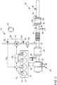
- Figure 1 shows the schematic representation of an internal combustion engine 10, whose outlet 18 is connected to an exhaust system 20.
- the internal combustion engine 10 is a direct-injection gasoline engine and has a plurality of combustion chambers 12.
- a spark plug 14 and a fuel injector 16 for injecting a fuel into the respective combustion chamber 12 are arranged on the combustion chambers 12.
- Inlet chambers and outlet valves are arranged on combustion chambers 12, with which a fluidic connection from the intake tract to combustion chambers 12 or from combustion chambers 12 to exhaust system 20 can be opened or closed.
- the exhaust gas system 20 comprises an exhaust gas duct 22, in which a turbine 26 of an exhaust gas turbocharger 24 is arranged in the flow direction of an exhaust gas of the internal combustion engine 10 through the exhaust gas duct 22 and a three-way catalytic converter 28 close to the engine is arranged downstream of the turbine 26.
- a particle filter 30 with a three-way catalytically active coating 32 which is also referred to as a four-way catalytic converter, is arranged downstream of the three-way catalytic converter 28 near the engine in an underbody position of a motor vehicle.
- the exhaust gas aftertreatment system further comprises a regeneration air system 50, with which regeneration air can be blown into the exhaust duct 22 downstream of the three-way catalytic converter 28 close to the engine and upstream of the particle filter 30 at an introduction point 48.
- the regeneration air system 50 comprises a regeneration air delivery element 52 and a regeneration air duct 54, which connects the regeneration air delivery element 52 with the inlet point 48 on the exhaust gas duct 22.
- a regeneration air valve 56 is arranged in the regeneration air duct 54, with which the regeneration air supply to the exhaust gas duct 22 can be released or blocked.
- the regeneration air valve 56 also prevents exhaust gas from flowing out of the exhaust duct in the direction of the regeneration air system 50.
- An air mass meter 58 in particular a hot-film air mass meter 60, is arranged in the regeneration air duct 54 upstream of the regeneration air conveying element 52.
- a regulator 68 is provided on the regeneration air system 50, with which the speed of the regeneration air conveying element 52 can be regulated.
- a first lambda probe 34 is arranged on the exhaust duct 22, which is designed as a broadband probe.
- a second lambda probe 36 is arranged downstream of the inlet point 48 and upstream of the particle filter 30, which is preferably designed as a jump probe.
- a differential pressure sensor 38 is provided in the exhaust gas duct 22, with which a pressure difference can be determined via the particle filter 30.
- a temperature sensor 40, 42 is provided upstream and downstream of the particle filter 30 in order to detect the exhaust gas temperatures upstream and downstream of the particle filter 30.
- a mixing section 44 is formed between the inlet point 48 and an inlet of the particle filter 30, in which the exhaust gas of the internal combustion engine 10 mixes with the fresh air from the regeneration air system 50.
- the internal combustion engine 10 is connected to an engine control unit 46, with which the fuel injection quantity, the ignition timing and the regeneration air quantity are regulated, among other things.
- the invention therefore provides for the hot film air mass meter 60 in the regeneration air duct 54 to be used for the precise air metering.
- the combustion air ratio in the combustion chambers 12 of the internal combustion engine 10 can be set very precisely via the mixture adaptation.
- the air mass flow supplied to the internal combustion engine 10 and the exhaust gas mass flow resulting therefrom can likewise be determined exactly by the engine control unit 46. With these two variables, the necessary regeneration air mass flow ⁇ SL to achieve the desired combustion air ratio upstream of the particle filter 30 can be calculated and passed on to the controller 68 of the regeneration air conveying element 52 as a controlled variable.
- FIG 2 A further exemplary embodiment of an exhaust gas aftertreatment system according to the invention for an internal combustion engine 10 is shown.
- the determination of the amount of regeneration air in the regeneration air system 50 is not made by a hot film air mass meter 60, but by pressure sensors 62, 64, which as Differential pressure sensor 66 determine a pressure difference ⁇ p via the regeneration air conveying element 52.
- This pressure difference ⁇ p and the speed n SL of the regeneration air conveying element 52 can be used to determine the regeneration air mass flow ⁇ SL in an alternative manner.
- the particle filter 30 is loaded with soot particles from the exhaust gas of the internal combustion engine 10. Since regeneration of the particle filter 30 requires a temperature of more than 600 ° C., such a temperature cannot be achieved or can only be achieved extremely difficultly by in-engine heating measures in low-load operation. Therefore, the particle filter 30 is provided with a catalytically active coating 32, which enables exothermic conversion of unburned exhaust gas components, in particular unburned hydrocarbons, carbon monoxide and hydrogen, while heating the particle filter 30.
- the internal combustion engine 10 is operated with a substoichiometric combustion air ratio ⁇ ⁇ 1 and at the same time regeneration air is blown into the exhaust gas duct 22.
- Such heating of the particle filter 30 is also referred to as chemical heating.
- the particle filter 30 only has to be heated to the light-off temperature of the catalytically active coating 32 for regeneration.
- the quantity of regeneration air can be increased while maintaining the chemical heating via the regeneration air system 50, so that an over-stoichiometric exhaust gas is established downstream of the inlet point 48.
- the soot retained in the particle filter 30 can be oxidized and the particle filter 30 can thus be regenerated.
- the substoichiometric operation of the internal combustion engine 10 on the three-way catalytic converter near the engine produces ammonia, which would be converted into nitrogen oxide in the particle filter 30 if the excess air was too high. Too little air supply would result in the emission of hydrocarbons, carbon monoxide and ammonia.
- a regeneration air mass flow ⁇ SL the temperature in the particulate filter 30 to reduce unwanted, is interrupted whereby the regeneration or run at a high soot loading of the particulate filter over a too high exotherm to thermal damage of the particulate filter 30th If the regeneration air mass flow ⁇ SL was too low, the regeneration would run too slowly and therefore cannot be completed within a reasonable time interval.
- FIG 3 A first operating state of the internal combustion engine 10 is shown, in which the particulate filter 30 is heated up exclusively by means of internal engine measures, such as an adjustment of the ignition angle in the "late" direction.
- the internal combustion engine 10 is operated with a stoichiometric combustion air ratio in order to enable an efficient conversion of the pollutants in the exhaust gas of the internal combustion engine 10 by the three-way catalytic converter 10 close to the engine.
- the regeneration air system 50 is deactivated and the regeneration air valve 56 is closed. This operating state is maintained as long as the catalytically active coating 32 of the particle filter 30 has not yet reached its light-off temperature.
- the internal combustion engine 10 When the three-way catalytically active coating 32 of the particle filter 30 has reached its light-off temperature of approximately 300 ° C., from which an efficient conversion of the pollutants in the exhaust gas of the internal combustion engine with the release of heat is possible, the internal combustion engine 10 becomes in Figure 4 shown operating state operated.
- the internal combustion engine 10 is operated with a substoichiometric combustion air ratio and, at the same time, regeneration air is blown into the exhaust gas duct 22 at the inlet point 48, so that a stoichiometric exhaust gas occurs at the inlet of the particle filter 30.
- the unburned exhaust gas components are reacted exothermally with the regeneration air on the catalytically active surface 32 of the particle filter 32 until the latter has reached its regeneration temperature of approximately 600 ° C.
- the amount of regeneration air increases, so that a stoichiometric exhaust gas occurs downstream of the inlet point 48.
- the soot particles retained in the particle filter 30 are oxidized with the residual oxygen in the exhaust gas, as a result of which the particle filter 30 is regenerated.
- the internal combustion engine 10 is preferably still operated with a substoichiometric combustion air ratio in order to maintain the chemical heating of the particle filter 30 during the regeneration and to prevent the particle filter 30 from cooling below its regeneration temperature.
Landscapes
- Engineering & Computer Science (AREA)
- Chemical & Material Sciences (AREA)
- Combustion & Propulsion (AREA)
- Mechanical Engineering (AREA)
- General Engineering & Computer Science (AREA)
- Chemical Kinetics & Catalysis (AREA)
- Health & Medical Sciences (AREA)
- Toxicology (AREA)
- Materials Engineering (AREA)
- Exhaust Gas After Treatment (AREA)
Applications Claiming Priority (1)
| Application Number | Priority Date | Filing Date | Title |
|---|---|---|---|
| DE102019100752.6A DE102019100752A1 (de) | 2019-01-14 | 2019-01-14 | Regenerationsluftsystem für ein Abgasnachbehandlungssystem eines Verbrennungsmotors sowie Verfahren zur Abgasnachbehandlung |
Publications (1)
| Publication Number | Publication Date |
|---|---|
| EP3680461A1 true EP3680461A1 (fr) | 2020-07-15 |
Family
ID=69159692
Family Applications (1)
| Application Number | Title | Priority Date | Filing Date |
|---|---|---|---|
| EP20151477.5A Withdrawn EP3680461A1 (fr) | 2019-01-14 | 2020-01-13 | Système d'air de régénération pour un système de traitement des gaz d'échappement d'un moteur à combustion interne et procédé de traitement des gaz d'échappement |
Country Status (4)
| Country | Link |
|---|---|
| US (1) | US11268421B2 (fr) |
| EP (1) | EP3680461A1 (fr) |
| CN (1) | CN111502801B (fr) |
| DE (1) | DE102019100752A1 (fr) |
Cited By (1)
| Publication number | Priority date | Publication date | Assignee | Title |
|---|---|---|---|---|
| IT202300020304A1 (it) * | 2023-10-02 | 2025-04-02 | Iveco Spa | Sistema motore veicolare migliorato |
Families Citing this family (8)
| Publication number | Priority date | Publication date | Assignee | Title |
|---|---|---|---|---|
| JP7003878B2 (ja) * | 2018-08-30 | 2022-01-21 | トヨタ自動車株式会社 | 内燃機関の排気浄化装置 |
| DE102019103001A1 (de) * | 2019-02-07 | 2020-08-13 | Bayerische Motoren Werke Aktiengesellschaft | Partikelfilterbaugruppe für Kraftfahrzeug, Kraftfahrzeug und Verfahren zum Regenerieren eines Partikelfilters |
| GB2607100B (en) * | 2021-05-28 | 2024-08-14 | Jaguar Land Rover Ltd | Exhaust system, controller and method for an internal combustion engine |
| CN113356985B (zh) * | 2021-06-02 | 2022-06-03 | 重庆长安汽车股份有限公司 | 一种颗粒捕集器再生控制方法、装置、系统及车辆 |
| US11698014B1 (en) | 2022-07-20 | 2023-07-11 | Garrett Transportation I Inc. | Flow estimation for secondary air system |
| DE102022211127A1 (de) * | 2022-10-20 | 2024-04-25 | Robert Bosch Gesellschaft mit beschränkter Haftung | Verfahren, Recheneinheit und Computerprogramm zum Betreiben eines Bren-ners |
| DE102022214198A1 (de) | 2022-12-21 | 2024-06-27 | Robert Bosch Gesellschaft mit beschränkter Haftung | Verfahren zum Betreiben einer Anlage zur Zuführung von Luft zu einem Brenner |
| JP2026508111A (ja) * | 2023-02-02 | 2026-03-10 | カミンズ インコーポレイテッド | 後処理システム内で排気温度を制御するためのシステムおよび方法 |
Citations (9)
| Publication number | Priority date | Publication date | Assignee | Title |
|---|---|---|---|---|
| DE10249421A1 (de) * | 2002-10-23 | 2004-05-13 | Siemens Ag | Verfahren zum Überwachen der Zufuhr von Sekundärluft in das Abgas einer Brennkraftmaschine |
| DE10257153A1 (de) | 2002-11-26 | 2004-06-03 | Robert Bosch Gmbh | Verfahren und Vorrichtung zur Bestimmung einer Sekundärluftmasse |
| DE102010037454A1 (de) | 2010-09-10 | 2012-03-15 | Hjs Emission Technology Gmbh & Co. Kg | Verfahren zum Regeln der einem Abgasbrenner zugeführten Luftmenge sowie Einrichtung zum Regeln der einem solchen Brenner zugeführten Luftmenge |
| DE102015212514A1 (de) * | 2015-07-03 | 2017-01-05 | Volkswagen Aktiengesellschaft | Verfahren zur Abgasnachbehandlung und Vorrichtung zur Reinigung des Abgases einer Brennkraftmaschine |
| DE102015215373A1 (de) * | 2015-08-12 | 2017-02-16 | Volkswagen Ag | Verfahren zur Regeneration von Abgasnachbehandlungskomponenten eines Verbrennungsmotors sowie Abgasnachbehandlungsvorrichtung für einen Verbrennungsmotor |
| DE102016206394A1 (de) * | 2016-04-15 | 2017-10-19 | Volkswagen Aktiengesellschaft | Verfahren und Vorrichtung zur Abgasnachbehandlung eines Verbrennungsmotors |
| DE102016211595A1 (de) * | 2016-06-28 | 2017-12-28 | Robert Bosch Gmbh | Verfahren und Vorrichtung zur Steuerung und/ oder Überwachung der Funktion einer Sekundärluftzuführung in einer Abgasreinigungsanlage |
| DE102016218818A1 (de) * | 2016-09-29 | 2018-03-29 | Audi Ag | Sekundärluftabhängige Lambdaregelung |
| DE102017115399A1 (de) * | 2017-07-10 | 2019-01-10 | Volkswagen Ag | Abgasnachbehandlungssystem und Verfahren zur Abgasnachbehandlung eines Verbrennungsmotors |
Family Cites Families (12)
| Publication number | Priority date | Publication date | Assignee | Title |
|---|---|---|---|---|
| JP2738251B2 (ja) * | 1993-01-20 | 1998-04-08 | 松下電器産業株式会社 | 内燃機関用フィルタ再生装置 |
| US5519992A (en) * | 1993-03-16 | 1996-05-28 | Mitsubishi Denki Kabushiki Kaisha | Exhaust gas purification system for internal combustion engine, and apparatus and method for controlling the same |
| US8677751B2 (en) * | 2009-07-24 | 2014-03-25 | Vandyne Superturbo, Inc. | Rich fuel mixture super-turbocharged engine system |
| US8438840B2 (en) * | 2009-09-29 | 2013-05-14 | Ford Global Technologies, Llc | Particulate filter regeneration in an engine |
| DE102010044102A1 (de) * | 2010-11-18 | 2012-05-24 | Ford Global Technologies, Llc | Abgasanlage für Brennkraftmaschinen mit Partikelfilter |
| US9255513B2 (en) * | 2012-05-25 | 2016-02-09 | Ford Global Technologies, Llc | Exhaust air injection |
| US9046016B2 (en) | 2012-11-08 | 2015-06-02 | GM Global Technology Operations LLC | System and method for particulate filter regeneration |
| US10465637B2 (en) * | 2013-02-28 | 2019-11-05 | Bendix Commercial Vehicle Systems, Llc | Method to enhance gas recirculation in turbocharged diesel engines |
| US10273851B2 (en) * | 2014-02-28 | 2019-04-30 | Scania Cv Ab | Exhaust treatment system and method for treatment of an exhaust stream |
| US9677448B2 (en) * | 2015-04-17 | 2017-06-13 | Ford Global Technologies, Llc | Method and system for reducing engine exhaust emissions |
| DE102016211274A1 (de) * | 2016-06-23 | 2017-12-28 | Volkswagen Aktiengesellschaft | Verfahren und Vorrichtung zur Abgasnachbehandlung eines Verbrennungsmotors |
| DE102016220831A1 (de) * | 2016-10-24 | 2018-04-26 | Volkswagen Aktiengesellschaft | Brennkraftmaschine mit einer Sekundärluftpumpe und Verfahren zum Betreiben einer Brennkraftmaschine mit einer Sekundärluftpumpe |
-
2019
- 2019-01-14 DE DE102019100752.6A patent/DE102019100752A1/de active Pending
-
2020
- 2020-01-13 EP EP20151477.5A patent/EP3680461A1/fr not_active Withdrawn
- 2020-01-14 CN CN202010036540.0A patent/CN111502801B/zh active Active
- 2020-01-14 US US16/741,947 patent/US11268421B2/en active Active
Patent Citations (9)
| Publication number | Priority date | Publication date | Assignee | Title |
|---|---|---|---|---|
| DE10249421A1 (de) * | 2002-10-23 | 2004-05-13 | Siemens Ag | Verfahren zum Überwachen der Zufuhr von Sekundärluft in das Abgas einer Brennkraftmaschine |
| DE10257153A1 (de) | 2002-11-26 | 2004-06-03 | Robert Bosch Gmbh | Verfahren und Vorrichtung zur Bestimmung einer Sekundärluftmasse |
| DE102010037454A1 (de) | 2010-09-10 | 2012-03-15 | Hjs Emission Technology Gmbh & Co. Kg | Verfahren zum Regeln der einem Abgasbrenner zugeführten Luftmenge sowie Einrichtung zum Regeln der einem solchen Brenner zugeführten Luftmenge |
| DE102015212514A1 (de) * | 2015-07-03 | 2017-01-05 | Volkswagen Aktiengesellschaft | Verfahren zur Abgasnachbehandlung und Vorrichtung zur Reinigung des Abgases einer Brennkraftmaschine |
| DE102015215373A1 (de) * | 2015-08-12 | 2017-02-16 | Volkswagen Ag | Verfahren zur Regeneration von Abgasnachbehandlungskomponenten eines Verbrennungsmotors sowie Abgasnachbehandlungsvorrichtung für einen Verbrennungsmotor |
| DE102016206394A1 (de) * | 2016-04-15 | 2017-10-19 | Volkswagen Aktiengesellschaft | Verfahren und Vorrichtung zur Abgasnachbehandlung eines Verbrennungsmotors |
| DE102016211595A1 (de) * | 2016-06-28 | 2017-12-28 | Robert Bosch Gmbh | Verfahren und Vorrichtung zur Steuerung und/ oder Überwachung der Funktion einer Sekundärluftzuführung in einer Abgasreinigungsanlage |
| DE102016218818A1 (de) * | 2016-09-29 | 2018-03-29 | Audi Ag | Sekundärluftabhängige Lambdaregelung |
| DE102017115399A1 (de) * | 2017-07-10 | 2019-01-10 | Volkswagen Ag | Abgasnachbehandlungssystem und Verfahren zur Abgasnachbehandlung eines Verbrennungsmotors |
Cited By (2)
| Publication number | Priority date | Publication date | Assignee | Title |
|---|---|---|---|---|
| IT202300020304A1 (it) * | 2023-10-02 | 2025-04-02 | Iveco Spa | Sistema motore veicolare migliorato |
| EP4534815A1 (fr) * | 2023-10-02 | 2025-04-09 | Iveco S.P.A. | Système de moteur de véhicule amélioré, procédé de commande et véhicule |
Also Published As
| Publication number | Publication date |
|---|---|
| CN111502801B (zh) | 2022-11-01 |
| CN111502801A (zh) | 2020-08-07 |
| US11268421B2 (en) | 2022-03-08 |
| US20200224573A1 (en) | 2020-07-16 |
| DE102019100752A1 (de) | 2020-07-16 |
Similar Documents
| Publication | Publication Date | Title |
|---|---|---|
| EP3680461A1 (fr) | Système d'air de régénération pour un système de traitement des gaz d'échappement d'un moteur à combustion interne et procédé de traitement des gaz d'échappement | |
| EP3686404B1 (fr) | Dispositif et procédé de post-traitement des gaz d'échappement d'un moteur à combustion interne | |
| EP1336037B1 (fr) | Procede et dispositif pour reguler un systeme de traitement subsequent de gaz d'echappement | |
| EP3772576B1 (fr) | Procede de chauffage d'un catalyseur et systeme de post-traitement des gaz d'echappement | |
| EP3683414B1 (fr) | Installation de gaz d'échappement pour un moteur à combustion interne et son procédé de fonctionnement | |
| DE102012021573A1 (de) | Verfahren zum Betreiben eines Brenners sowie Abgasanlage mit einem derart betreibbaren Brenner | |
| DE102016211274A1 (de) | Verfahren und Vorrichtung zur Abgasnachbehandlung eines Verbrennungsmotors | |
| DE102008032601A1 (de) | Verfahren zum Einstellen eines Zustandes eines Abgasstroms einer Brennkraftmaschine eines Kraftfahrzeuges | |
| EP3584418B1 (fr) | Système de post-traitement des gaz d'échappement et procédé de régénération d'un filtre à particules | |
| DE102022206800A1 (de) | Verfahren zum Betreiben eines Abgasbrenners, Vorrichtung zur Durchführung eines solchen Verfahrens und Kraftfahrzeug | |
| EP3604751B1 (fr) | Procédé de post-traitement des gaz d'échappement d'un moteur à combustion interne et système de post-traitement des gaz d'échappement | |
| EP3208450A1 (fr) | Procédé de fonctionnement d'un moteur à combustion interne et moteur à trois cylindres destiné à exécuter ledit procédé | |
| DE10130054B4 (de) | Abgasanlage einer mehrzylindrigen Verbrennungskraftmaschine und Verfahren zur Reinigung eines Abgases | |
| DE102018132466A1 (de) | Verfahren und Vorrichtung zur Abgasnachbehandlung eines Verbrennungsmotors | |
| DE102016202349A1 (de) | Verfahren und Vorrichtung zur Abgasnachbehandlung eines Verbrennungsmotors | |
| DE102017115399A1 (de) | Abgasnachbehandlungssystem und Verfahren zur Abgasnachbehandlung eines Verbrennungsmotors | |
| EP3770386B1 (fr) | Système de post-traitement des gaz d'échappement et procédé de post-traitement des gaz d'échappement d'un moteur à combustion interne | |
| EP2294292B1 (fr) | Procédé et dispositif pour faire fonctionner un système de post-traitement des gaz d'échappement | |
| DE102021113204B4 (de) | Verfahren zur Temperatursteuerung eines elektrisch beheizbaren Katalysators | |
| WO2008012005A1 (fr) | Moteur à combustion interne à allumage commandé pour carburants gazeux, et procédé de fonctionnement d'un tel moteur à combustion interne | |
| DE102019108016B4 (de) | Verfahren zur Regeneration eines Partikelfilters | |
| DE102019117755B4 (de) | Abgasnachbehandlungssystem und Verfahren zur Abgasnachbehandlung eines Verbrennungsmotors | |
| DE102021107433A1 (de) | Verbrennungsmotor sowie Verfahren zum Betreiben eines Verbrennungsmotors | |
| DE102020211089A1 (de) | Verfahren zur Steuerung eines Brenners in einem Abgasstrang einer Brennkraftmaschine | |
| DE102021119349B4 (de) | Verfahren zur Steuerung eines Verbrennungsmotors mit Sekundärluftsystem |
Legal Events
| Date | Code | Title | Description |
|---|---|---|---|
| PUAI | Public reference made under article 153(3) epc to a published international application that has entered the european phase |
Free format text: ORIGINAL CODE: 0009012 |
|
| STAA | Information on the status of an ep patent application or granted ep patent |
Free format text: STATUS: THE APPLICATION HAS BEEN PUBLISHED |
|
| AK | Designated contracting states |
Kind code of ref document: A1 Designated state(s): AL AT BE BG CH CY CZ DE DK EE ES FI FR GB GR HR HU IE IS IT LI LT LU LV MC MK MT NL NO PL PT RO RS SE SI SK SM TR |
|
| AX | Request for extension of the european patent |
Extension state: BA ME |
|
| STAA | Information on the status of an ep patent application or granted ep patent |
Free format text: STATUS: REQUEST FOR EXAMINATION WAS MADE |
|
| 17P | Request for examination filed |
Effective date: 20210115 |
|
| RBV | Designated contracting states (corrected) |
Designated state(s): AL AT BE BG CH CY CZ DE DK EE ES FI FR GB GR HR HU IE IS IT LI LT LU LV MC MK MT NL NO PL PT RO RS SE SI SK SM TR |
|
| STAA | Information on the status of an ep patent application or granted ep patent |
Free format text: STATUS: EXAMINATION IS IN PROGRESS |
|
| 17Q | First examination report despatched |
Effective date: 20210309 |
|
| STAA | Information on the status of an ep patent application or granted ep patent |
Free format text: STATUS: THE APPLICATION IS DEEMED TO BE WITHDRAWN |
|
| 18D | Application deemed to be withdrawn |
Effective date: 20210720 |