EP3680463A1 - Mischer für eine abgasanlage einer brennkraftmaschine - Google Patents
Mischer für eine abgasanlage einer brennkraftmaschine Download PDFInfo
- Publication number
- EP3680463A1 EP3680463A1 EP19216797.1A EP19216797A EP3680463A1 EP 3680463 A1 EP3680463 A1 EP 3680463A1 EP 19216797 A EP19216797 A EP 19216797A EP 3680463 A1 EP3680463 A1 EP 3680463A1
- Authority
- EP
- European Patent Office
- Prior art keywords
- mixer
- wall
- transition
- area
- connection
- Prior art date
- Legal status (The legal status is an assumption and is not a legal conclusion. Google has not performed a legal analysis and makes no representation as to the accuracy of the status listed.)
- Granted
Links
Images

Classifications
-
- F—MECHANICAL ENGINEERING; LIGHTING; HEATING; WEAPONS; BLASTING
- F01—MACHINES OR ENGINES IN GENERAL; ENGINE PLANTS IN GENERAL; STEAM ENGINES
- F01N—GAS-FLOW SILENCERS OR EXHAUST APPARATUS FOR MACHINES OR ENGINES IN GENERAL; GAS-FLOW SILENCERS OR EXHAUST APPARATUS FOR INTERNAL-COMBUSTION ENGINES
- F01N13/00—Exhaust or silencing apparatus characterised by constructional features
- F01N13/18—Construction facilitating manufacture, assembly, or disassembly
- F01N13/1838—Construction facilitating manufacture, assembly, or disassembly characterised by the type of connection between parts of exhaust or silencing apparatus, e.g. between housing and tubes, between tubes and baffles
-
- F—MECHANICAL ENGINEERING; LIGHTING; HEATING; WEAPONS; BLASTING
- F01—MACHINES OR ENGINES IN GENERAL; ENGINE PLANTS IN GENERAL; STEAM ENGINES
- F01N—GAS-FLOW SILENCERS OR EXHAUST APPARATUS FOR MACHINES OR ENGINES IN GENERAL; GAS-FLOW SILENCERS OR EXHAUST APPARATUS FOR INTERNAL-COMBUSTION ENGINES
- F01N3/00—Exhaust or silencing apparatus having means for purifying, rendering innocuous, or otherwise treating exhaust
- F01N3/08—Exhaust or silencing apparatus having means for purifying, rendering innocuous, or otherwise treating exhaust for rendering innocuous
- F01N3/10—Exhaust or silencing apparatus having means for purifying, rendering innocuous, or otherwise treating exhaust for rendering innocuous by thermal or catalytic conversion of noxious components of exhaust
- F01N3/18—Exhaust or silencing apparatus having means for purifying, rendering innocuous, or otherwise treating exhaust for rendering innocuous by thermal or catalytic conversion of noxious components of exhaust characterised by methods of operation; Control
- F01N3/20—Exhaust or silencing apparatus having means for purifying, rendering innocuous, or otherwise treating exhaust for rendering innocuous by thermal or catalytic conversion of noxious components of exhaust characterised by methods of operation; Control specially adapted for catalytic conversion
- F01N3/206—Adding periodically or continuously substances to exhaust gases for promoting purification, e.g. catalytic material in liquid form, NOx reducing agents
- F01N3/2066—Selective catalytic reduction [SCR]
-
- F—MECHANICAL ENGINEERING; LIGHTING; HEATING; WEAPONS; BLASTING
- F01—MACHINES OR ENGINES IN GENERAL; ENGINE PLANTS IN GENERAL; STEAM ENGINES
- F01N—GAS-FLOW SILENCERS OR EXHAUST APPARATUS FOR MACHINES OR ENGINES IN GENERAL; GAS-FLOW SILENCERS OR EXHAUST APPARATUS FOR INTERNAL-COMBUSTION ENGINES
- F01N3/00—Exhaust or silencing apparatus having means for purifying, rendering innocuous, or otherwise treating exhaust
- F01N3/08—Exhaust or silencing apparatus having means for purifying, rendering innocuous, or otherwise treating exhaust for rendering innocuous
- F01N3/10—Exhaust or silencing apparatus having means for purifying, rendering innocuous, or otherwise treating exhaust for rendering innocuous by thermal or catalytic conversion of noxious components of exhaust
- F01N3/24—Exhaust or silencing apparatus having means for purifying, rendering innocuous, or otherwise treating exhaust for rendering innocuous by thermal or catalytic conversion of noxious components of exhaust characterised by constructional aspects of converting apparatus
- F01N3/28—Construction of catalytic reactors
- F01N3/2892—Exhaust flow directors or the like, e.g. upstream of catalytic device
-
- B—PERFORMING OPERATIONS; TRANSPORTING
- B01—PHYSICAL OR CHEMICAL PROCESSES OR APPARATUS IN GENERAL
- B01F—MIXING, e.g. DISSOLVING, EMULSIFYING OR DISPERSING
- B01F25/00—Flow mixers; Mixers for falling materials, e.g. solid particles
- B01F25/40—Static mixers
- B01F25/42—Static mixers in which the mixing is affected by moving the components jointly in changing directions, e.g. in tubes provided with baffles or obstructions
- B01F25/43—Mixing tubes, e.g. wherein the material is moved in a radial or partly reversed direction
- B01F25/431—Straight mixing tubes with baffles or obstructions that do not cause substantial pressure drop; Baffles therefor
- B01F25/4315—Straight mixing tubes with baffles or obstructions that do not cause substantial pressure drop; Baffles therefor the baffles being deformed flat pieces of material
-
- B—PERFORMING OPERATIONS; TRANSPORTING
- B01—PHYSICAL OR CHEMICAL PROCESSES OR APPARATUS IN GENERAL
- B01F—MIXING, e.g. DISSOLVING, EMULSIFYING OR DISPERSING
- B01F25/00—Flow mixers; Mixers for falling materials, e.g. solid particles
- B01F25/40—Static mixers
- B01F25/42—Static mixers in which the mixing is affected by moving the components jointly in changing directions, e.g. in tubes provided with baffles or obstructions
- B01F25/43—Mixing tubes, e.g. wherein the material is moved in a radial or partly reversed direction
- B01F25/431—Straight mixing tubes with baffles or obstructions that do not cause substantial pressure drop; Baffles therefor
- B01F25/4317—Profiled elements, e.g. profiled blades, bars, pillars, columns or chevrons
- B01F25/43171—Profiled blades, wings, wedges, i.e. plate-like element having one side or part thicker than the other
-
- B—PERFORMING OPERATIONS; TRANSPORTING
- B01—PHYSICAL OR CHEMICAL PROCESSES OR APPARATUS IN GENERAL
- B01F—MIXING, e.g. DISSOLVING, EMULSIFYING OR DISPERSING
- B01F25/00—Flow mixers; Mixers for falling materials, e.g. solid particles
- B01F25/40—Static mixers
- B01F25/42—Static mixers in which the mixing is affected by moving the components jointly in changing directions, e.g. in tubes provided with baffles or obstructions
- B01F25/43—Mixing tubes, e.g. wherein the material is moved in a radial or partly reversed direction
- B01F25/431—Straight mixing tubes with baffles or obstructions that do not cause substantial pressure drop; Baffles therefor
- B01F25/43197—Straight mixing tubes with baffles or obstructions that do not cause substantial pressure drop; Baffles therefor characterised by the mounting of the baffles or obstructions
- B01F25/431974—Support members, e.g. tubular collars, with projecting baffles fitted inside the mixing tube or adjacent to the inner wall
-
- F—MECHANICAL ENGINEERING; LIGHTING; HEATING; WEAPONS; BLASTING
- F01—MACHINES OR ENGINES IN GENERAL; ENGINE PLANTS IN GENERAL; STEAM ENGINES
- F01N—GAS-FLOW SILENCERS OR EXHAUST APPARATUS FOR MACHINES OR ENGINES IN GENERAL; GAS-FLOW SILENCERS OR EXHAUST APPARATUS FOR INTERNAL-COMBUSTION ENGINES
- F01N13/00—Exhaust or silencing apparatus characterised by constructional features
- F01N13/08—Other arrangements or adaptations of exhaust conduits
- F01N13/082—Other arrangements or adaptations of exhaust conduits of tailpipe, e.g. with means for mixing air with exhaust for exhaust cooling, dilution or evacuation
-
- F—MECHANICAL ENGINEERING; LIGHTING; HEATING; WEAPONS; BLASTING
- F01—MACHINES OR ENGINES IN GENERAL; ENGINE PLANTS IN GENERAL; STEAM ENGINES
- F01N—GAS-FLOW SILENCERS OR EXHAUST APPARATUS FOR MACHINES OR ENGINES IN GENERAL; GAS-FLOW SILENCERS OR EXHAUST APPARATUS FOR INTERNAL-COMBUSTION ENGINES
- F01N3/00—Exhaust or silencing apparatus having means for purifying, rendering innocuous, or otherwise treating exhaust
-
- F—MECHANICAL ENGINEERING; LIGHTING; HEATING; WEAPONS; BLASTING
- F01—MACHINES OR ENGINES IN GENERAL; ENGINE PLANTS IN GENERAL; STEAM ENGINES
- F01N—GAS-FLOW SILENCERS OR EXHAUST APPARATUS FOR MACHINES OR ENGINES IN GENERAL; GAS-FLOW SILENCERS OR EXHAUST APPARATUS FOR INTERNAL-COMBUSTION ENGINES
- F01N3/00—Exhaust or silencing apparatus having means for purifying, rendering innocuous, or otherwise treating exhaust
- F01N3/08—Exhaust or silencing apparatus having means for purifying, rendering innocuous, or otherwise treating exhaust for rendering innocuous
-
- F—MECHANICAL ENGINEERING; LIGHTING; HEATING; WEAPONS; BLASTING
- F01—MACHINES OR ENGINES IN GENERAL; ENGINE PLANTS IN GENERAL; STEAM ENGINES
- F01N—GAS-FLOW SILENCERS OR EXHAUST APPARATUS FOR MACHINES OR ENGINES IN GENERAL; GAS-FLOW SILENCERS OR EXHAUST APPARATUS FOR INTERNAL-COMBUSTION ENGINES
- F01N2240/00—Combination or association of two or more different exhaust treating devices, or of at least one such device with an auxiliary device, not covered by indexing codes F01N2230/00 or F01N2250/00, one of the devices being
- F01N2240/20—Combination or association of two or more different exhaust treating devices, or of at least one such device with an auxiliary device, not covered by indexing codes F01N2230/00 or F01N2250/00, one of the devices being a flow director or deflector
-
- F—MECHANICAL ENGINEERING; LIGHTING; HEATING; WEAPONS; BLASTING
- F01—MACHINES OR ENGINES IN GENERAL; ENGINE PLANTS IN GENERAL; STEAM ENGINES
- F01N—GAS-FLOW SILENCERS OR EXHAUST APPARATUS FOR MACHINES OR ENGINES IN GENERAL; GAS-FLOW SILENCERS OR EXHAUST APPARATUS FOR INTERNAL-COMBUSTION ENGINES
- F01N2610/00—Adding substances to exhaust gases
- F01N2610/02—Adding substances to exhaust gases the substance being ammonia or urea
-
- F—MECHANICAL ENGINEERING; LIGHTING; HEATING; WEAPONS; BLASTING
- F01—MACHINES OR ENGINES IN GENERAL; ENGINE PLANTS IN GENERAL; STEAM ENGINES
- F01N—GAS-FLOW SILENCERS OR EXHAUST APPARATUS FOR MACHINES OR ENGINES IN GENERAL; GAS-FLOW SILENCERS OR EXHAUST APPARATUS FOR INTERNAL-COMBUSTION ENGINES
- F01N3/00—Exhaust or silencing apparatus having means for purifying, rendering innocuous, or otherwise treating exhaust
- F01N3/08—Exhaust or silencing apparatus having means for purifying, rendering innocuous, or otherwise treating exhaust for rendering innocuous
- F01N3/10—Exhaust or silencing apparatus having means for purifying, rendering innocuous, or otherwise treating exhaust for rendering innocuous by thermal or catalytic conversion of noxious components of exhaust
- F01N3/18—Exhaust or silencing apparatus having means for purifying, rendering innocuous, or otherwise treating exhaust for rendering innocuous by thermal or catalytic conversion of noxious components of exhaust characterised by methods of operation; Control
- F01N3/20—Exhaust or silencing apparatus having means for purifying, rendering innocuous, or otherwise treating exhaust for rendering innocuous by thermal or catalytic conversion of noxious components of exhaust characterised by methods of operation; Control specially adapted for catalytic conversion
- F01N3/206—Adding periodically or continuously substances to exhaust gases for promoting purification, e.g. catalytic material in liquid form, NOx reducing agents
-
- Y—GENERAL TAGGING OF NEW TECHNOLOGICAL DEVELOPMENTS; GENERAL TAGGING OF CROSS-SECTIONAL TECHNOLOGIES SPANNING OVER SEVERAL SECTIONS OF THE IPC; TECHNICAL SUBJECTS COVERED BY FORMER USPC CROSS-REFERENCE ART COLLECTIONS [XRACs] AND DIGESTS
- Y02—TECHNOLOGIES OR APPLICATIONS FOR MITIGATION OR ADAPTATION AGAINST CLIMATE CHANGE
- Y02T—CLIMATE CHANGE MITIGATION TECHNOLOGIES RELATED TO TRANSPORTATION
- Y02T10/00—Road transport of goods or passengers
- Y02T10/10—Internal combustion engine [ICE] based vehicles
- Y02T10/12—Improving ICE efficiencies
Definitions
- the present invention relates to a mixer for an exhaust system of an internal combustion engine, comprising a mixer body with a plurality of flow deflection elements which extend radially outward from a mixer body center with respect to a longitudinal axis of the mixer and a support region which adjoins the longitudinal axis of the mixer and surrounds the longitudinal axis of the ring in a ring.
- Such mixers are used in exhaust systems in order to bring about an efficient mixing of reactant injected further upstream into the exhaust stream, for example a urea / water solution, with the exhaust gas emitted by an internal combustion engine.
- the mixer body is supported by the carrier area with respect to exhaust gas-carrying components of the exhaust gas system in such a way that its flow deflection elements can be flowed around by the exhaust gas flowing in the exhaust gas-carrying components and can thereby generate the swirling required for mixing.
- the two walls providing a connection to the mixer body on the one hand and an exhaust pipe on the other hand are connected to one another in such a way that in the transition, that is to say in the region of the first transition surface, corner or edge regions, which in the case of the essentially continuously concave configuration the unavoidable thermal expansion of the mixer body are subject to a strong mechanical load and therefore show a tendency to crack, can be avoided.
- a structure which avoids the formation of excessively high local stresses even when the mixer body is thermally expanded can be supported in an advantageous embodiment, for example, by increasing the radius of curvature of the concavely curved first transition surface from the connection of the first transition surface to the inner wall surface to the connection of the first transition surface to the outer wall surface .
- the radius of curvature increases continuously, that is, there are no regions with constant or decreasing radius of curvature.
- a constant radius of curvature can also be present in intermediate regions.
- a radial distance of the outer wall surface from the inner wall surface towards an axially open end of the pipe receiving intermediate space distant from the first transition surface increases. This can be achieved, for example, in that the inner wall surface is a cylindrical surface and / or in that the outer wall surface is a truncated cone surface.
- the pipe connection wall can have a substantially constant wall thickness.
- the mixer body support wall has a first support wall area providing the outer wall surface on a radial outside and one to the adjoining the first support wall area and providing at least part of the first transition surface, and that the mixer body support wall has a constant wall thickness in the first support wall area and / or has a wall thickness increasing in the direction away from the first support wall area.
- Such a structure, which also supports the flow guidance in the direction of the mixer body or its flow guide elements, can be achieved, for example, in that the mixer body support wall in the second support wall region on its side facing away from the first transition surface, one on an inner peripheral surface of the mixer connection region and one Has an inner circumferential surface of the first support wall area adjoining second transition surface, and that the second transition surface in its extension area between the inner circumferential surface of the mixer connection area and the inner circumferential surface of the first support wall area has no surface normal parallel to the longitudinal axis of the mixer or / and a radial distance of the second transition surface to the longitudinal axis of the mixer in its inner circumferential area of the mixer connection area and the inner circumferential surface of the first support wall area decreases continuously and / or a radial distance of the inner circumferential surface of the first support wall area from the longitudinal axis of the mixer decreases axially in the direction away from the second transition area.
- the inner peripheral surface of the mixer connection area is a cylindrical surface, and / or that the inner peripheral surface of the mixer connection area and the inner wall surface are arranged radially offset from one another, or / and that the inner peripheral surface of the first support wall area is a truncated cone surface.
- the mixer connection area has a connecting flange projecting radially outward beyond the pipe connection wall with an essentially axially oriented contact surface for contacting an adjacent one has exhaust system component to be positioned on the mixer.
- the mixer connection area can be connected gas-tight to the exhaust system component, for example using a pipe clamp or the like surrounding it and a complementary connection area of an exhaust system component.
- the structural design of the mixer constructed according to the invention enables the carrier area with its mixer connection area, its pipe connection wall and its mixer body support wall and the mixer body can be formed with its mixer body center and its flow deflection elements as an integral metal casting.
- a structure leading to low stresses even under thermal stress can also be achieved in that a transition of the first transition surface into the inner wall surface and a transition of the first transition surface into the outer wall surface are axially offset from one another.
- the transition of the first transition surface into the outer wall surface is axially further away from an apex region of the first transition surface than the transition of the first transition surface into the inner wall surface.
- the present invention further relates to an exhaust system for an internal combustion engine, comprising a mixer constructed according to the invention.
- an exhaust pipe can be connected to the pipe connection wall, preferably by welding, in contact with the inner wall surface of the pipe connection wall.
- a mixer for an exhaust system of an internal combustion engine is generally designated 10.
- the mixer 10 comprises a mixer body 12 with, for example, a mixer body center 14 arranged centrally with respect to a longitudinal axis L of the mixer and a plurality of vane-like flow deflection elements 16 starting from the mixer body center 14 or adjoining one another in the region of the mixer body center 14.
- leading edges 18 oriented in the upstream direction and the in FIG Downstream or circumferentially oriented trailing edges 20 of the flow deflection elements 16 are offset from one another in the circumferential direction, so that the exhaust gas to be flowed onto the mixer 10 in an exhaust gas flow direction A and mixed with reactant is deflected in the circumferential direction when flowing through the mixer 10 or the mixer body 12 is whirled in the process.
- An efficient mixing of the exhaust gas with the reactant injected into it is achieved in the swirl flow thus generated.
- the surfaces of the flow deflecting elements 16 heated by the exhaust gas flow help to support the evaporation of the reagent impinging on them in droplet form.
- the flow deflection elements 16 adjoin a support region of the mixer 10, generally designated 22, radially on the outside.
- the carrier area 22 surrounds the longitudinal axis L of the mixer in a ring-like manner, thus forming a ring which is closed in the circumferential direction.
- the carrier region 22 has a mixer connection region 24.
- the mixer connection area 24 is formed with a connection flange 26 projecting radially outwards and a contact surface 28 provided thereon and essentially axially oriented. With the contact surface 28, the mixer connection area 24 can be positioned for contact with the exhaust gas system component to be positioned upstream of the mixer 10.
- the carrier area 22 comprises a pipe connection wall 30 which extends essentially in the direction of the longitudinal axis L of the mixer.
- a pipe connection wall 30 can be used to connect an exhaust system component, in particular an exhaust pipe, which is to be fixedly connected to the mixer 10 and is therefore connected downstream thereof.
- the pipe connection wall 30 provides an inner wall surface 32, essentially designed as a cylindrical surface, against which the exhaust pipe to be firmly connected to the support region 22 can be positioned.
- the carrier area 22 further comprises a mixer body support wall 34 adjoining the mixer connection area 24 and also the pipe connection wall 30.
- the flow deflection elements 16 of the mixer body 12 adjoin the mixer body support wall 34 in the region of their leading edges 18. It should be pointed out that the entire mixer 10 with its carrier region 22 and its mixer body 12 can be produced as an integral metal casting, that is to say a metal block. If necessary, material-removing processing steps can then be carried out after such a casting production process, for example in order to make the contact surface 28 completely flat in order to produce a gas-tight connection.
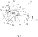
- the mixer body support wall 34 provides an outer wall surface 36 oriented radially outwards. Between the inner wall surface 32 of the pipe connection wall 30 and the outer wall surface 36 of the mixer body support wall 34 there is an intermediate pipe receiving space which is open in the downstream direction 38 formed. This is closed in the upstream direction by a first transition surface 40 formed essentially on the mixer body support wall 34.
- the first transition surface 40 closes in the area of an in Fig. 2 dividing line T 1 shown on the inner wall surface 32 and closes in the area of a in Fig. 2 dividing line T 2 shown on the outer wall surface 36.
- the pipe connection wall 30 has a substantially constant wall thickness, that is to say in this region it has an outer peripheral surface 42 designed as a cylindrical surface.
- the mixer body support wall 34 is formed with an essentially constant wall thickness starting from the dividing line T 2 . It can be seen that the radial distance between the pipe connection wall 30 and the mixer body support wall 34, essentially also the radial distance between the inner wall surface 32 and the outer wall surface 36, increases in the direction away from the first transition surface 40.
- a first support wall area 44 of the mixer body support wall 34 which essentially also provides the outer wall surface, can be designed to taper conically, so that the outer wall surface 36 and likewise an inner peripheral surface 46 of the first support wall area 44 are designed as frustoconical surfaces.
- An inner circumferential surface 48 of the mixer connection region 24 is adjoined in the region of a dividing line T 3 by a second transition surface 50, for example extending to the dividing line T 2 .
- This essentially radially inward oriented second transition surface 50 is provided on a second support wall area 52 of the mixer body support wall 34 and is designed such that it does not have a surface normal parallel to the longitudinal axis L of the mixer in any of its areas lying between the two dividing lines T 3 and T 2 . That is, at every point of the second transition surface 50, the surface normal thereof has an extension component oriented in the radial direction with respect to the longitudinal axis L of the mixer.
- the first transition surface 40 between the area in which it adjoins the dividing line T 1 to the inner wall surface 32 and the area in which it adjoins the dividing line T 2 to the outer wall surface 36 is continuously concave, so that the second support wall area 52 forms, with this concavely curved first transition surface 40, a correspondingly concavely curved floor area of the tube receiving intermediate space 38, which is circumferential around the longitudinal axis L of the mixer.
- the first transition surface 40 is designed such that, in its concave shape, the radius of curvature starts from the dividing line T 1 , that is to say the region in which the first transition surface 40 adjoins the inner wall surface 32, up to that region in which at the dividing line T 2 the first transition surface 40 adjoins the outer wall surface 36 increases.
- the increase can particularly advantageously be continuous, so that there is essentially no region with a constant or decreasing radius of curvature between the dividing lines T 1 and T 2 . In connection with the shape of the second transition surface 50, this results in an increasing wall thickness for the second support wall area 52 starting from the dividing line T 2 , i.e.
- connection to the first support wall area 44 up to the area in which the second support wall area 52 connects to the mixer connection area 24 or the pipe connection wall 30 connects.
- the region in which the first transition surface 40 merges into the wall outer surface 36 on the line T 2 lies axially offset with respect to the region in which the first transition surface 40 merges into the wall inner surface 32 on the line T 1 in such a way that the transition at line T 2 is axially further away from an apex region S.
- the first transition surface 40 lies as the transition at the line T 1 . This supports a gradual, step-free or kink-free transition of the first transition surface 40 into the outer wall surface 36. It should be pointed out that the apex region S of the first transition surface 40 is the region in which the latter has a maximum distance from those in FIGS Fig. 2 Axial end faces of the pipe connection wall 30 or the mixer body support wall 34 which can be seen on the right.
- the flow deflection elements 16 connect to the mixer body support wall 34 in such a way that their most upstream-oriented regions, that is to say the leading edges 18, are axially spaced from the first transition surface 40, in particular to the region in which they lie on the Partition line T 2 passes into the outer wall surface 36.
- the mixer body 12 will expand thermally. This thermal expansion can follow the radial expansion of the mixer body 12 due to the shape of the carrier region 22 on the one hand and due to the connection of the flow deflection elements 16 to the mixer body support wall 34 axially offset to the first transition surface 40.
- the second support wall area 52 essentially forms a pivot or articulation point in the area D thereof. Since there are no corners, edges or steps in any area of the different merging surfaces, the formation of excessively large local stresses in the radial expansion of the mixer body 12 is avoided in this way. Furthermore, due to the comparatively large radial distance between the pipe connection wall 30 and the mixer body support wall 34, this radial expansion movement is not impaired by any sections of the carrier region 22.
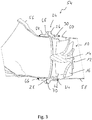
- the Fig. 3 shows the integration of the mixer 10 in an exhaust system, generally designated 54, of an internal combustion engine.
- This exhaust system 54 comprises an upstream exhaust pipe 56, in the area of which, for example, an injector provided for injecting the reactant can be arranged.
- the Exhaust system 54 further comprises a downstream exhaust pipe 58, which is inserted, for example, with a radially widened end region 60 into the pipe receiving space 38 of the mixer 10 in such a way that it bears against the inner wall surface 32.
- the exhaust pipe 58 is connected to the pipe connecting wall 30 in a material-locking manner by means of a weld seam 62 which preferably runs in the circumferential direction.
- a connecting element 64 that is complementary in shape to the pipe connection region 24 of the mixer 10 is fixed, for example by a weld seam 66.
- the connecting element 64 has a flange region 68 which is complementary to the flange region 26 of the mixer connection region 24 which projects radially outward beyond the pipe connection wall 30.
- the flange area 26 is positioned with its contact surface 28 opposite a contact surface 70 of the flange region 68, it being possible, for example, to position an annular sealing element between these two contact surfaces 28, 70.
- a pipe clamp or the like which surrounds the two flange regions 26, 68 radially on the outside and also radially overlaps, can be provided, by means of which a gas-tight, firm cohesion of the mixer connection region 24 with the connection element 64 is achieved.
- screw bolts can be passed through the two flange regions 26, 68 in order to ensure stable cohesion.
- the first transition surface while maintaining the principle of a substantially continuous concave shape between the regions in which it adjoins the inner wall surface and the outer wall surface, can be locally formed, for example with a constant radius of curvature, or it could, for example, starting from the region in which the first transition surface adjoins the inner wall surface, first decrease the radius of curvature of the first transition surface, for example up to close to or to the apex region of the first transition surface, and then increase again in the direction of the outer wall surface.
- the flow deflection elements can also be arranged with a shape or positioning that deviates from the shape shown, with respect to the center of the mixer body.
Landscapes
- Chemical & Material Sciences (AREA)
- Engineering & Computer Science (AREA)
- Chemical Kinetics & Catalysis (AREA)
- Combustion & Propulsion (AREA)
- Mechanical Engineering (AREA)
- General Engineering & Computer Science (AREA)
- Dispersion Chemistry (AREA)
- Health & Medical Sciences (AREA)
- Toxicology (AREA)
- Exhaust Gas After Treatment (AREA)
Abstract
- einen Mischerverbindungsbereich (24) zum Verbinden des Mischers (10) mit einer an den Mischer (10) angrenzend zu positionierenden Abgasanlagenkomponente,
- eine an den Mischerverbindungsbereich (24) anschließende Rohrverbindungswand (30) mit einer Wandinnenfläche (32),
- eine an den Mischerverbindungsbereich (24) anschließende, den Mischerkörper (12) tragende und von der Rohrverbindungswand (30) radial außen umgebene Mischerkörper-Tragewand (34) mit einer Wandaußenfläche (36),
- eine an die Wandaußenfläche (36) und die Wandinnenfläche (32) anschließende erste Übergangsfläche (40), wobei die erste Übergangsfläche (40) zwischen der Wandinnenfläche (32) und der Wandaußenfläche (36) im Wesentlichen durchgehend konkav gewölbt ist und einen zwischen der Rohrverbindungswand (30) und der Mischerkörper-Tragewand (34) gebildeten ringartigen Rohraufnahmezwischenraum (38) axial begrenzt.
Description
- Die vorliegende Erfindung betrifft einen Mischer für eine Abgasanlage einer Brennkraftmaschine, umfassend einen Mischerkörper mit einer Mehrzahl von von einem Mischerkörperzentrum bezüglich einer Mischerlängsachse nach radial außen sich erstreckenden Strömungsablenkelementen sowie einen an den Mischerkörper radial außen anschließenden, die Mischerlängsachse ringartig umgebenden Trägerbereich.
- Derartige Mischer werden in Abgasanlagen eingesetzt, um eine effiziente Durchmischung von weiter stromaufwärts in den Abgasstrom eingespritztem Reaktionsmittel, beispielsweise einer Harnstoff/Wasser-Lösung, mit dem von einer Brennkraftmaschine ausgestoßenen Abgas herbeizuführen. Durch den Trägerbereich ist der Mischerkörper bezüglich abgasführenden Komponenten der Abgasanlage so getragen, dass dessen Strömungsablenkelemente von dem in den abgasführenden Komponenten strömenden Abgas umströmt werden können und dabei die für die Durchmischung erforderliche Verwirbelung erzeugen können.
- Es ist die Aufgabe der vorliegenden Erfindung, einen Mischer für eine Abgasanlage einer Brennkraftmaschine mit einem einfach zu realisierendem, gleichwohl unter den im Verbrennungsbetrieb auftretenden thermischen und mechanischen Belastungen stabilem Aufbau bereitzustellen.
- Erfindungsgemäß wird diese Aufgabe gelöst durch einen Mischer für eine Abgasanlage einer Brennkraftmaschine, umfassend einen Mischerkörper mit einer Mehrzahl von von einem Mischerkörperzentrum bezüglich einer Mischerlängsachse nach radial außen sich erstreckenden Strömungsablenkelementen sowie einen an den Mischerkörper radial außen anschließenden, die Mischerlängsachse ringartig umgebenden Trägerbereich, wobei der Trägerbereich umfasst:
- einen Mischerverbindungsbereich zum Verbinden des Mischers mit einer an den Mischer angrenzend zu positionierenden Abgasanlagenkomponente,
- eine an den Mischerverbindungsbereich anschließende Rohrverbindungswand mit einer Wandinnenfläche,
- eine an den Mischerverbindungsbereich anschließende, den Mischerkörper tragende und von der Rohrverbindungswand radial außen umgebene Mischerkörper-Tragewand mit einer Wandaußenfläche,
- eine an die Wandaußenfläche und die Wandinnenfläche anschließende erste Übergangsfläche, wobei die erste Übergangsfläche zwischen der Wandinnenfläche und der Wandaußenfläche im Wesentlichen durchgehend konkav gewölbt ist und einen zwischen der Rohrverbindungswand und der Mischerkörper-Tragewand gebildeten ringartigen Rohraufnahmezwischenraum axial begrenzt.
- Bei dem erfindungsgemäß aufgebauten Mischer sind die beiden eine Anbindung an den Mischerkörper einerseits und ein Abgasrohr andererseits bereitstellenden Wände so aneinander angeschlossen, dass im Übergang, also im Bereich der ersten Übergangsfläche, durch die im Wesentlichen durchgehend konkav gewölbte Ausgestaltung Ecken- oder Kantenbereiche, welche bei der unvermeidbar auftretenden thermischen Ausdehnung des Mischerkörpers einer starken mechanischen Belastung unterliegen und daher eine Tendenz zur Rissbildung zeigen, vermieden werden.
- Ein auch bei thermischer Ausdehnung des Mischerkörpers das Entstehen lokal übermäßig starker Spannungen vermeidender Aufbau kann bei einer vorteilhaften Ausgestaltung beispielsweise dadurch unterstützt werden, dass ein Krümmungsradius der konkav gewölbten ersten Übergangsfläche vom Anschluss der ersten Übergangsfläche an die Wandinnenfläche zum Anschluss der ersten Übergangsfläche an die Wandaußenfläche zunimmt. Dabei kann beispielsweise vorgesehen sein, dass der Krümmungsradius stetig zunimmt, also keine Bereiche mit konstantem oder abnehmendem Krümmungsradius vorhanden sind. Alternativ ist es beispielsweise möglich, dass, ausgehend vom Anschluss an die Wandinnenfläche, zunächst ein kurzer Bereich mit abnehmendem Krümmungsradius vorhanden ist, auf welchen dann ein langer Bereich mit bis zum Anschluss an die Wandaußenfläche zunehmendem Krümmungsradius folgt. In Zwischenbereichen kann auch ein konstanter Krümmungsradius vorhanden sein.
- Um eine weiter erhöhte Flexibilität im Trägerbereich bereitstellen zu können und auch eine definierte Strömungsführung in Richtung auf den Mischerkörper zu unterstützen zu können, wird vorgeschlagen, dass ein radialer Abstand der Wandaußenfläche zur Wandinnenfläche in Richtung zu einem von der ersten Übergangsfläche entfernten axial offenen Ende des Rohraufnahmezwischenraums zunimmt. Dies kann beispielsweise dadurch erreicht werden, dass die Wandinnenfläche eine Zylinderfläche ist, oder/und dass die Wandaußenfläche eine Kegelstumpffläche ist.
- Im axialen Erstreckungsbereich der Wandinnenfläche kann die Rohrverbindungswand eine im Wesentlichen konstante Wanddicke aufweisen.
- Für eine hohe Flexibilität der Mischerkörper-Tragewand einerseits, eine gleichwohl stabile Anbindung der Mischerkörper-Tragewand an die Rohrverbindungswand bzw. den Mischer Verbindungsbereich andererseits kann vorgesehen sein, dass die Mischerkörper-Tragewand einen an einer radialen Außenseite die Wandaußenfläche bereitstellenden ersten Tragewandbereich und einen an den ersten Tragewandbereich anschließenden und wenigstens einen Teil der ersten Übergangsfläche bereitstellenden zweiten Tragewandbereich aufweist, und dass die Mischerkörper-Tragewand im ersten Tragewandbereich eine konstante Wanddicke aufweist oder/und im zweiten Tragewandbereich eine in Richtung vom ersten Tragewandbereich weg zunehmende Wanddicke aufweist.
- Eine derartige auch die Strömungsführung in Richtung auf den Mischerkörper bzw. dessen Strömungsleitelemente zu unterstützende Struktur kann beispielsweise dadurch erreicht werden, dass die Mischerkörper-Tragewand im zweiten Tragewandbereich an ihrer von der ersten Übergangsfläche abgewandten Seite eine an eine Innenumfangsfläche des Mischerverbindungsbereichs und eine Innenumfangsfläche des ersten Tragewandbereichs anschließende zweite Übergangsfläche aufweist, und dass die zweite Übergangsfläche in ihrem Erstreckungsbereich zwischen der Innenumfangsfläche des Mischerverbindungsbereichs und der Innenumfangsfläche des ersten Tragewandbereichs keine zur Mischerlängsachse parallele Flächennormale aufweist oder/und ein Radialabstand der zweiten Übergangsfläche zur Mischerlängsachse in ihrem Erstreckungsbereich zwischen der Innenumfangsfläche des Mischerverbindungsbereichs und der Innenumfangsfläche des ersten Tragewandbereichs stufenlos abnimmt oder/und ein Radialabstand der Innenumfangsfläche des ersten Tragewandbereichs zur Mischerlängsachse axial in Richtung von der zweiten Übergangsfläche weg abnimmt.
- Dabei kann beispielsweise vorgesehen sein, dass die Innenumfangsfläche des Mischerverbindungsbereichs eine Zylinderfläche ist, oder/und dass Innenumfangsfläche des Mischerverbindungsbereichs und die Wandinnenfläche zueinander radial versetzt angeordnet sind, oder/und dass die Innenumfangsfläche des ersten Tragewandbereichs eine Kegelstumpffläche ist.
- Für eine stabile und einfach zu realisierende Verbindung des erfindungsgemäß aufgebauten Mischers mit einer insbesondere stromaufwärts in einer Abgasanlage daran anschließenden Abgasanlagenkomponente kann weiter vorgesehen sein, dass der Mischerverbindungsbereich einen nach radial außen über die Rohrverbindungswand vorspringenden Verbindungsflansch mit einer im Wesentlichen axial orientierten Anlagefläche zur Anlage einer angrenzend an den Mischer zu positionierenden Abgasanlagenkomponente aufweist. Bei derartiger Ausgestaltung kann der Mischerverbindungsbereich beispielsweise unter Einsatz einer diesen und einen komplementären Verbindungsbereich einer Abgasanlagenkomponente umgebenden Rohrschelle oder dergleichen mit der Abgasanlagenkomponente gasdicht verbunden werden.
- Die bauliche Ausgestaltung des erfindungsgemäß aufgebauten Mischers ermöglicht es, dass der Trägerbereich mit seinem Mischerverbindungsbereich, seiner Rohrverbindungswand und seiner Mischerkörper-Tragewand und der Mischerkörper mit seinem Mischerkörperzentrum und seinen Strömungsablenkelementen als integrales Metallgussteil ausgebildet werden können.
- Um bei einer durch Umströmung mit Abgas herbeigeführten thermischen Ausdehnung des Mischerkörpers die Flexibilität des Trägerbereichs insbesondere im Bereich der Mischerkörper-Tragewand effizient ausnutzen zu können, wird weiter vorgeschlagen, dass wenigstens ein Teil der, vorzugsweise alle Strömungsablenkelemente mit axialem Abstand zur ersten Übergangsfläche an die Mischerkörper-Tragewand anschließen.
- Ein auch unter thermischer Belastung zu geringen Spannungen führender Aufbau kann ferner dadurch erreicht werden, dass ein Übergang der ersten Übergangsfläche in die Wandinnenfläche und ein Übergang der ersten Übergangsfläche in die Wandaußenfläche zueinander axial versetzt liegen. Insbesondere kann dabei vorgesehen sein, der Übergang der ersten Übergangsfläche in die Wandaußenfläche von einem Scheitelbereich der ersten Übergangsfläche axial weiter entfernt liegt als der Übergang der ersten Übergangsfläche in die Wandinnenfläche.
- Die vorliegende Erfindung betrifft ferner eine Abgasanlage für eine Brennkraftmaschine, umfassend einen erfindungsgemäß aufgebauten Mischer.
- Dabei kann ein Abgasrohr an der Wandinnenfläche der Rohrverbindungswand anliegend mit der Rohrverbindungswand vorzugsweise durch Verschweißen verbunden sein.
- Um auch bei mit der Rohrverbindungswand an der Wandinnenfläche anliegend verbundenem Abgasrohr eine radiale Bewegung der Mischerkörper-Tragewand zu ermöglichen, wird vorgeschlagen, dass ein radialer Abstand zwischen der Wandinnenfläche der Rohrverbindungswand und der Wandaußenfläche der Mischerkörper-Tragewand größer ist als, vorzugsweise wenigstens doppelt so groß ist wie, eine Wanddicke des mit der Rohrverbindungswand verbundenen Abgasrohrs. Die Erfindung wird nachfolgend mit Bezug auf die beiliegenden Figuren detailliert beschrieben. Es zeigt:
- Fig. 1
- eine perspektivische Längsschnittansicht eines erfindungsgemäß aufgebauten Mischers;
- Fig. 2
- eine vergrößerte Detailansicht des Mischers der
Fig. 1 ; - Fig. 3
- eine Längsschnittansicht eines einen Mischer der
Fig. 1 enthaltenden Teils einer Abgasanlage einer Brennkraftmaschine. - In
Fig. 1 ist ein Mischer für eine Abgasanlage einer Brennkraftmaschine allgemein mit 10 bezeichnet. Der Mischer 10 umfasst einen Mischerkörper 12 mit einem beispielsweise bezüglich einer Mischerlängsachse L zentrisch angeordneten Mischerkörperzentrum 14 und einer Mehrzahl von von dem Mischerkörperzentrum 14 ausgehenden bzw. im Bereich des Mischerkörperzentrums 14 aneinander anschließenden schaufelartigen Strömungsablenkelementen 16. Die in Richtung stromaufwärts orientierten Anströmkanten 18 und die in Richtung stromabwärts bzw. in Umfangsrichtung orientierten Abströmkanten 20 der Strömungsablenkelemente 16 sind in Umfangsrichtung zueinander versetzt, so dass das in einer Abgasströmungsrichtung A auf den Mischer 10 zu strömende und mit Reaktionsmittel durchsetzte Abgas beim Durchströmen des Mischers 10 bzw. des Mischerkörpers 12 in Umfangsrichtung abgelenkt und dabei verwirbelt wird. In der so erzeugten Drallströmung wird eine effiziente Durchmischung des Abgases mit dem in dieses eingespritzten Reaktionsmittel erreicht. Ferner tragen die durch den Abgasstrom erwärmten Oberflächen der Strömungsablenkelemente 16 dazu bei, die Abdampfung von in Tröpfchenform auf diese auftreffendem Reaktionsmittel zu unterstützen. - Radial außen schließen die Strömungsablenkelemente 16 an einen allgemein mit 22 bezeichneten Trägerbereich des Mischers 10 an. Der Trägerbereich 22 umgibt die Mischerlängsachse L ringartig, bildet also einen in Umfangsrichtung geschlossenen Ring. Zu der nachfolgend mit Bezug auf die
Fig. 3 detailliert beschriebenen Verbindung des Mischers 22 mit einer stromaufwärts bezüglich diesem positionierten Abgasanlagenkomponente weist der Trägerbereich 22 einen Mischerverbindungsbereich 24 auf. Der Mischerverbindungsbereich 24 ist mit einem nach radial außen vorspringenden Verbindungsflansch 26 und einer an diesem vorgesehenen und im Wesentlichen axial orientierten Anlagefläche 28 ausgebildet. Mit der Anlagefläche 28 kann der Mischerverbindungsbereich 24 zur Anlage an der stromaufwärts an den Mischer 10 anschließend zu positionierenden Abgasanlagenkomponente positioniert werden. - Anschließend an den Mischerverbindungsbereich 24 umfasst der Trägerbereich 22 eine im Wesentlichen in Richtung der Mischerlängsachse L sich erstreckende Rohrverbindungswand 30. Mit der Rohrverbindungswand 30 kann eine mit dem Mischer 10 fest zu verbindende und somit stromabwärts an diesen anschließende Abgasanlagenkomponente, insbesondere ein Abgasrohr, verbunden werden. Dazu stellt die Rohrverbindungswand 30 eine im Wesentlichen als Zylinderfläche ausgebildete Wandinnenfläche 32 bereit, an welcher das mit dem Trägerbereich 22 fest zu verbindende Abgasrohr anliegend positioniert werden kann.
- Der Trägerbereich 22 umfasst ferner eine an den Mischerverbindungsbereich 24 bzw. auch die Rohrverbindungswand 30 anschließende Mischerkörper-Tragewand 34. An die Mischerkörper-Tragewand 34 schließen die Strömungsablenkelemente 16 des Mischerkörpers 12 im Bereich ihrer Anströmkanten 18 an. Es ist darauf hinzuweisen, dass der gesamte Mischer 10 mit seinem Trägerbereich 22 und seinem Mischerkörper 12 als integrales Metallgussteil, also ein Metallblock, hergestellt werden kann. Sofern erforderlich, können anschließend an einen derartigen Gießherstellungsvorgang noch materialabhebende Bearbeitungsschritte vorgenommen werden, beispielsweise um die Anlagefläche 28 zur Herstellung einer gasdichten Verbindung vollkommen plan zu gestalten.
- Die Mischerkörper-Tragewand 34 stellt eine nach radial außen orientierte Wandaußenfläche 36 bereit. Zwischen der Wandinnenfläche 32 der Rohrverbindungswand 30 und der Wandaußenfläche 36 der Mischerkörper-Tragewand 34 ist ein in Richtung stromabwärts offener Rohraufnahmezwischenraum 38 gebildet. Dieser ist in Richtung stromaufwärts durch eine im Wesentlichen an der Mischerkörper-Tragewand 34 ausgebildete erste Übergangsfläche 40 abgeschlossen. Die erste Übergangsfläche 40 schließt im Bereich einer in
Fig. 2 dargestellten Trennlinie T1 an die Wandinnenfläche 32 an und schließt im Bereich einer inFig. 2 dargestellten Trennlinie T2 an die Wandaußenfläche 36 an. Die Rohrverbindungswand 30 weist, ausgehend von der Trennlinie T1 bis zu ihrem vom Mischerverbindungsbereich 24 entfernten axialen Endbereich eine im Wesentlichen konstante Wanddicke auf, weist in diesem Bereich also eine als Zylinderfläche ausgebildete Außenumfangsfläche 42 auf. Gleichermaßen ist die Mischerkörper-Tragewand 34 ausgehend von der Trennlinie T2 mit im Wesentlichen konstanter Wanddicke ausgebildet. Man erkennt, dass der radiale Abstand zwischen der Rohrverbindungswand 30 und der Mischerkörper-Tragewand 34, im Wesentlichen also auch der radiale Abstand zwischen der Wandinnenfläche 32 und der Wandaußenfläche 36 in Richtung von der ersten Übergangsfläche 40 weg zunimmt. Um dies zu erreichen, kann beispielsweise ein im Wesentlichen auch die Wandaußenfläche bereitstellender erster Tragewandbereich 44 der Mischerkörper-Tragewand 34 sich konisch verjüngend ausgebildet sein, so dass die Wandaußenfläche 36 und gleichermaßen eine Innenumfangsfläche 46 des ersten Tragewandbereichs 44 als Kegelstumpfflächen ausgebildet sind. - An eine Innenumfangsfläche 48 des Mischerverbindungsbereichs 24 schließt im Bereich einer Trennlinie T3 eine beispielsweise bis zur Trennlinie T2 sich erstreckende zweite Übergangsfläche 50 an. Diese im Wesentlichen nach radial innen orientierte zweite Übergangsfläche 50 ist an einem zweiten Tragewandbereich 52 der Mischerkörper-Tragewand 34 vorgesehen und ist so gestaltet, dass sie in keinem ihrer zwischen den beiden Trennlinien T3 und T2 liegenden Bereiche eine zur Mischerlängsachse L parallele Flächennormale aufweist. Das heißt, an jeder Stelle der zweiten Übergangsfläche 50 weist deren Flächennormale eine in radialer Richtung bezüglich der Mischerlängsachse L orientierte Erstreckungskomponente auf. Dadurch werden stufenartige Übergänge mit radial sich erstreckenden Flächenbereichen zwischen der beispielsweise ebenfalls als Zylinderfläche ausgebildeten Innenumfangsfläche 48 des Mischerverbindungsbereichs 24 und der Innenumfangsfläche 46 des ersten Tragewandbereichs 44 vermieden. Es ergibt sich ein geschwungener, stufenfreier Übergang, durch welchen das mit Reaktionsmittel durchsetzte Abgas auch im radial äußeren Bereich ohne wesentlichen Strömungswiderstand in Richtung auf die Strömungsablenkelemente 16 zu geleitet wird.
- Bei dem Mischer 10 ist die erste Übergangsfläche 40 zwischen dem Bereich, in welchem sie an der Trennlinie T1 an die Wandinnenfläche 32 anschließt, und dem Bereich, in welchem sie an der Trennlinie T2 an die Wandaußenfläche 36 anschließt, durchgehend konkav gewölbt, so dass der zweite Tragewandbereich 52 mit dieser konkav gewölbten ersten Übergangsfläche 40 einen entsprechend konkav gewölbten, in Umfangsrichtung um die Mischerlängsachse L ringartig umlaufenden Bodenbereich des Rohraufnahmezwischenraums 38 bildet. Ferner ist bei einer besonders vorteilhaften Ausgestaltung die erste Übergangsfläche 40 so gestaltet, dass bei deren konkaver Gestalt der Krümmungsradius ausgehend von der Trennlinie T1, also dem Bereich, in welchem die erste Übergangsfläche 40 an die Wandinnenfläche 32 anschließt, bis zu demjenigen Bereich, in welchem an der Trennlinie T2 die erste Übergangsfläche 40 an die Wandaußenfläche 36 anschließt, zunimmt. Die Zunahme kann besonders vorteilhaft stetig sein, so dass zwischen den Trennlinien T1 und T2 im Wesentlichen kein Bereich mit konstantem oder abnehmendem Krümmungsradius vorhanden ist. In Verbindung mit der Formgebung der zweiten Übergangsfläche 50 ergibt sich somit für den zweiten Tragewandbereich 52 eine ausgehend von der Trennlinie T2, also dem Anschluss an den ersten Tragewandbereich 44, zunehmende Wanddicke bis zu demjenigen Bereich, in welchem der zweite Tragewandbereich 52 an den Mischerverbindungsbereich 24 bzw. die Rohrverbindungswand 30 anschließt. Dabei besteht vorzugsweise weder am Übergang des zweiten Tragewandbereich 52 zum Mischerverbindungsbereich 24 bzw. zur Innenumfangsfläche 48 desselben, noch am Übergang des zweiten Tragewandbereichs 52 zur Rohrverbindungswand 30 bzw. zur Wandinnenfläche 32 derselben ein knickartiger bzw. stufenartiger Übergang. Ferner liegt der Bereich, in welchem an der Linie T2 die erste Übergangsfläche 40 in die Wandaußenfläche 36 übergeht, axial versetzten bezüglich des Bereichs, in welchem an der Linie T1 die erste Übergangsfläche 40 in die Wandinnenfläche 32 übergeht, und zwar derart, dass der Übergang an der Linie T2 axial weiter entfernt von einem Scheitelbereich S der ersten Übergangsfläche 40 liegt, als der Übergang an der Linie T1. Dadurch wird ein allmählicher, stufen- bzw. knickfreier Übergang der ersten Übergangsfläche 40 in die Wandaußenfläche 36 unterstützt. Es ist darauf hinzuweisen, dass der Scheitelbereich S der ersten Übergangsfläche 40 derjenige Bereich ist, in welchem diese einen maximalen Abstand zu den in
Fig. 2 rechts erkennbaren axialen Endflächen der Rohrverbindungswand 30 bzw. der Mischerkörper-Tragewand 34 aufweist. - In
Fig. 1 ist deutlich zu erkennen, dass die Strömungsablenkelemente 16 derart an die Mischerkörper-Tragewand 34 anschließen, dass deren am weitesten stromaufwärts orientierten Bereiche, also die Anströmkanten 18, in axialem Abstand zur ersten Übergangsfläche 40 liegen, insbesondere zu demjenigen Bereich, in welchem diese an der Trennlinie T2 in die Wandaußenfläche 36 übergeht. Bei der Umströmung des Mischers 10 mit dem von einer Brennkraftmaschine ausgestoßenen heißen Abgas wird der Mischerkörper 12 sich thermisch ausdehnen. Dieser thermischen Ausdehnung kann aufgrund der Formgebung des Trägerbereichs 22 einerseits und aufgrund des zur ersten Übergangsfläche 40 axial versetzten Anschlusses der Strömungsablenkelemente 16 an die Mischerkörper-Tragewand 34 andererseits die Mischerkörper-Tragewand 34 dieser radialen Ausdehnung des Mischerkörpers 12 folgen. Dabei bildet der zweite Tragewandbereich 52 im Wesentlichen im Bereich D desselben einen Dreh- bzw. Gelenkpunkt. Da in keinem Bereich der verschiedenen ineinander übergehenden Flächen Ecken, Kanten oder Stufen vorhanden sind, wird das Entstehen übermäßig großer lokaler Spannung bei der radialen Ausdehnung des Mischerkörpers 12 auf diese Art und Weise vermieden. Ferner wird aufgrund des vergleichsweise großen radialen Abstandes zwischen der Rohrverbindungswand 30 und der Mischerkörper-Tragewand 34 diese radiale Ausdehnungsbewegung nicht durch irgendwelche Abschnitte des Trägerbereichs 22 beeinträchtigt. - Die
Fig. 3 zeigt die Integration des Mischers 10 in eine allgemein mit 54 bezeichnete Abgasanlage einer Brennkraftmaschine. Diese Abgasanlage 54 umfasst ein stromaufwärtiges Abgasrohr 56, in dessen Bereich beispielsweise ein zum Einspritzen des Reaktionsmittels vorgesehener Injektor angeordnet sein kann. Die Abgasanlage 54 umfasst ferner ein stromabwärtiges Abgasrohr 58, das mit einem beispielsweise radial etwas aufgeweiteten Endbereich 60 in den Rohraufnahmezwischenraum 38 des Mischers 10 derart eingesetzt ist, dass es an der Wandinnenfläche 32 anliegt. Durch eine in Umfangsrichtung vorzugsweise umlaufende Schweißnaht 62 ist das Abgasrohr 58 mit der Rohrverbindungswand 30 materialschlüssig verbunden. - An dem stromaufwärts bezüglich des Mischers 10 positionierten Abgasrohr 56 ist ein zum Rohrverbindungsbereich 24 des Mischers 10 komplementär geformtes Verbindungselement 64 beispielsweise durch eine Schweißnaht 66 festgelegt. Das Verbindungselement 64 weist einen zu dem nach radial außen über die Rohrverbindungswand 30 vorspringenden Flanschbereich 26 des Mischerverbindungsbereichs 24 komplementären Flanschbereich 68 auf. Der Flanschbereich 26 ist mit seiner Anlagefläche 28 einer Anlagefläche 70 des Flanschbereichs 68 gegenüberliegend positioniert, wobei beispielsweise zwischen diesen beiden Anlageflächen 28, 70 ein ringartiges Dichtungselement positioniert werden kann. Zur festen Verbindung kann eine die beiden Flanschbereiche 26, 68 radial außen umgebende und diese auch radial übergreifende Rohrschelle oder dergleichen vorgesehen werden, durch welche ein gasdichter, fester Zusammenhalt des Mischerverbindungsbereichs 24 mit dem Verbindungselement 64 erreicht wird. Bei einer alternativen Ausgestaltung können beispielsweise Schraubbolzen durch die beiden Flanschbereiche 26, 68 hindurchgeführt werden, um einen stabilen Zusammenhalt zu gewährleisten.
- Mit dem vorangehend beschriebenen Aufbau eines Mischers wird bei der Möglichkeit, diesen mit all seinen Systembereichen als integrales, also einstückiges bzw. aus einem Materialblock geformtes Bauteil bereitzustellen, eine Formgebung erreicht, welche eine thermische Ausdehnung des Mischerkörpers ermöglicht, ohne dass dabei lokal übermäßig große Spannungen entstehen. Somit führt auch eine über die Betriebslebensdauer eines derartigen Mischers auftretende große Anzahl an Ausdehnzyklen nicht zu der Gefahr, dass im Bereich lokal großer Spannungen Risse entstehen, welche ein Loslösen des Mischerkörpers vom Trägerbereich zur Folge haben könnten.
- Es ist darauf hinzuweisen, dass bei dem vorangehend beschriebenen und in den Figuren dargestellten Mischer verschiedenste Variationen möglich sind, ohne von dem vorangehend beschriebenen wesentlichen Aufbauprinzip dieses Mischers abzuweichen. So ist es beispielsweise möglich, die Innenumfangsfläche des Mischerverbindungsbereichs nicht nach radial innen bezüglich der Wandinnenfläche versetzt anzuordnen, sondern beispielsweise auf gleichem radialen Niveau oder nach radial außen versetzt bezüglich dieser. Auch kann die erste Übergangsfläche bei Beibehalt des Prinzips einer im Wesentlichen durchlaufend konkaven Formgebung zwischen den Bereichen, in welchen diese an die Wandinnenfläche und die Wandaußenfläche anschließt, lokal beispielsweise mit konstantem Krümmungsradius ausgebildet sein, oder es könnte, beispielsweise ausgehend von dem Bereich, in welchem die erste Übergangsfläche an die Wandinnenfläche anschließt, zunächst der Krümmungsradius der ersten Übergangsfläche abnehmen, beispielsweise bis nahe an oder zu dem Scheitelbereich der ersten Übergangsfläche, um dann in Richtung zur Wandaußenfläche wieder zuzunehmen. Auch können selbstverständlich die Strömungsablenkelemente mit von der dargestellten Formgebung abweichender Formgebung bzw. Positionierung auch bezüglich des Mischerkörperzentrums angeordnet sein.
Claims (15)
- Mischer für eine Abgasanlage einer Brennkraftmaschine, umfassend einen Mischerkörper (12) mit einer Mehrzahl von von einem Mischerkörperzentrum (14) bezüglich einer Mischerlängsachse (L) nach radial außen sich erstreckenden Strömungsablenkelementen (16) sowie einen an den Mischerkörper (12) radial außen anschließenden, die Mischerlängsachse (L) ringartig umgebenden Trägerbereich (22), wobei der Trägerbereich (22) umfasst:- einen Mischerverbindungsbereich (24) zum Verbinden des Mischers (10) mit einer an den Mischer (10) angrenzend zu positionierenden Abgasanlagenkomponente,- eine an den Mischerverbindungsbereich (24) anschließende Rohrverbindungswand (30) mit einer Wandinnenfläche (32),- eine an den Mischerverbindungsbereich (24) anschließende, den Mischerkörper (12) tragende und von der Rohrverbindungswand (30) radial außen umgebene Mischerkörper-Tragewand (34) mit einer Wandaußenfläche (36),- eine an die Wandaußenfläche (36) und die Wandinnenfläche (32) anschließende erste Übergangsfläche (40), wobei die erste Übergangsfläche (40) zwischen der Wandinnenfläche (32) und der Wandaußenfläche (36) im Wesentlichen durchgehend konkav gewölbt ist und einen zwischen der Rohrverbindungswand (30) und der Mischerkörper-Tragewand (34) gebildeten ringartigen Rohraufnahmezwischenraum (38) axial begrenzt.
- Mischer nach Anspruch 1, dadurch gekennzeichnet, dass ein Krümmungsradius der konkav gewölbten ersten Übergangsfläche (40) vom Anschluss der ersten Übergangsfläche (40) an die Wandinnenfläche (32) zum Anschluss der ersten Übergangsfläche (40) an die Wandaußenfläche (36) zunimmt.
- Mischer nach Anspruch 1 oder 2, dadurch gekennzeichnet, dass ein radialer Abstand der Wandaußenfläche (36) zur Wandinnenfläche (32) in Richtung zu einem von der ersten Übergangsfläche (40) entfernten axial offenen Ende des Rohraufnahmezwischenraums (38) zunimmt.
- Mischer nach einem der vorangehenden Ansprüche, dadurch gekennzeichnet, dass die Wandinnenfläche (32) eine Zylinderfläche ist, oder/und dass die Wandaußenfläche (36) eine Kegelstumpffläche ist.
- Mischer nach einem der vorangehenden Ansprüche, dadurch gekennzeichnet, dass im axialen Erstreckungsbereich der Wandinnenfläche (32) die Rohrverbindungswand (30) eine im Wesentlichen konstante Wanddicke aufweist.
- Mischer nach einem der vorangehenden Ansprüche, dadurch gekennzeichnet, dass die Mischerkörper-Tragewand (34) einen an einer radialen Außenseite die Wandaußenfläche (36) bereitstellenden ersten Tragewandbereich (44) und einen an den ersten Tragewandbereich (44) anschließenden und wenigstens einen Teil der ersten Übergangsfläche (40) bereitstellenden zweiten Tragewandbereich (52) aufweist, und dass die Mischerkörper-Tragewand (34) im ersten Tragewandbereich (44) eine konstante Wanddicke aufweist oder/und im zweiten Tragewandbereich (52) eine in Richtung vom ersten Tragewandbereich (44) weg zunehmende Wanddicke aufweist.
- Mischer nach Anspruch 6, dadurch gekennzeichnet, dass die Mischerkörper-Tragewand (34) im zweiten Tragewandbereich (52) an ihrer von der ersten Übergangsfläche (40) abgewandten Seite eine an eine Innenumfangsfläche (48) des Mischerverbindungsbereichs (24) und eine Innenumfangsfläche (46) des ersten Tragewandbereichs (44) anschließende zweite Übergangsfläche (50) aufweist, und dass die zweite Übergangsfläche (50) in ihrem Erstreckungsbereich zwischen der Innenumfangsfläche (48) des Mischerverbindungsbereichs (24) und der Innenumfangsfläche (46) des ersten Tragewandbereichs (44) keine zur Mischerlängsachse (L) parallele Flächennormale aufweist oder/und ein Radialabstand der zweiten Übergangsfläche (50) zur Mischerlängsachse (L) in ihrem Erstreckungsbereich zwischen der Innenumfangsfläche (48) des Mischerverbindungsbereichs (24) und der Innenumfangsfläche (46) des ersten Tragewandbereichs (44) stufenlos abnimmt oder/und ein Radialabstand der Innenumfangsfläche (46) des ersten Tragewandbereichs (42) zur Mischerlängsachse (L) axial in Richtung von der zweiten Übergangsfläche (50) weg abnimmt.
- Mischer nach Anspruch 7, dadurch gekennzeichnet, dass die Innenumfangsfläche (48) des Mischerverbindungsbereichs (24) eine Zylinderfläche ist, oder/und dass Innenumfangsfläche (48) des Mischerverbindungsbereichs (24) und die Wandinnenfläche (32) zueinander radial versetzt angeordnet sind, oder/und dass die Innenumfangsfläche (46) des ersten Tragewandbereichs (44) eine Kegelstumpffläche ist.
- Mischer nach einem der vorangehenden Ansprüche, dadurch gekennzeichnet, dass der Mischerverbindungsbereich (24) einen nach radial außen über die Rohrverbindungswand (30) vorspringenden Verbindungsflansch (26) mit einer im Wesentlichen axial orientierten Anlagefläche (28) zur Anlage einer angrenzend an den Mischer (10) zu positionierenden Abgasanlagenkomponente aufweist.
- Mischer nach einem der vorangehenden Ansprüche, dadurch gekennzeichnet, dass der Trägerbereich (22) mit seinem Mischerverbindungsbereich (24), seiner Rohrverbindungswand (30) und seiner Mischerkörper-Tragewand (34) und der Mischerkörper (12) mit seinem Mischerkörperzentrum (14) und seinen Strömungsablenkelementen (16) als integrales Metallgussteil ausgebildet sind.
- Mischer nach einem der vorangehenden Ansprüche, dadurch gekennzeichnet, dass wenigstens ein Teil der Strömungsablenkelemente (16) mit axialem Abstand zur ersten Übergangsfläche (40) an die Mischerkörper-Tragewand (34) anschließt.
- Mischer nach einem der vorangehenden Ansprüche, dadurch gekennzeichnet, dass ein Übergang der ersten Übergangsfläche (40) in die Wandinnenfläche (32) und ein Übergang der ersten Übergangsfläche (40) in die Wandaußenfläche (36) zueinander axial versetzt liegen, vorzugsweise wobei der Übergang der ersten Übergangsfläche (40) in die Wandaußenfläche (36) von einem Scheitelbereich (S) der ersten Übergangsfläche (40) axial weiter entfernt liegt als der Übergang der ersten Übergangsfläche (40) in die Wandinnenfläche (32).
- Abgasanlage für eine Brennkraftmaschine, umfassend einen Mischer (10) nach einem der vorangehenden Ansprüche.
- Abgasanlage nach Anspruch 13, dadurch gekennzeichnet, dass ein Abgasrohr (58) an der Wandinnenfläche (32) der Rohrverbindungswand (30) anliegend mit der Rohrverbindungswand (30) vorzugsweise durch Verschweißen verbunden ist.
- Abgasanlage nach Anspruch 14, dadurch gekennzeichnet, dass ein radialer Abstand zwischen der Wandinnenfläche (32) der Rohrverbindungswand (30) und der Wandaußenfläche (36) der Mischerkörper-Tragewand (34) größer ist als, vorzugsweise wenigstens doppelt so groß ist wie, eine Wanddicke des mit der Rohrverbindungswand (30) verbundenen Abgasrohrs (58).
Applications Claiming Priority (1)
| Application Number | Priority Date | Filing Date | Title |
|---|---|---|---|
| DE102019100267.2A DE102019100267A1 (de) | 2019-01-08 | 2019-01-08 | Mischer für eine Abgasanlage einer Brennkraftmaschine |
Publications (2)
| Publication Number | Publication Date |
|---|---|
| EP3680463A1 true EP3680463A1 (de) | 2020-07-15 |
| EP3680463B1 EP3680463B1 (de) | 2021-03-31 |
Family
ID=68917771
Family Applications (1)
| Application Number | Title | Priority Date | Filing Date |
|---|---|---|---|
| EP19216797.1A Active EP3680463B1 (de) | 2019-01-08 | 2019-12-17 | Mischer für eine abgasanlage einer brennkraftmaschine |
Country Status (4)
| Country | Link |
|---|---|
| US (1) | US10697347B1 (de) |
| EP (1) | EP3680463B1 (de) |
| CN (1) | CN111412049B (de) |
| DE (1) | DE102019100267A1 (de) |
Families Citing this family (2)
| Publication number | Priority date | Publication date | Assignee | Title |
|---|---|---|---|---|
| DE102018107768A1 (de) * | 2018-04-03 | 2019-10-10 | Eberspächer Exhaust Technology GmbH & Co. KG | Mischerbaugruppe |
| DE102019127882A1 (de) * | 2019-10-16 | 2021-04-22 | Eberspächer Exhaust Technology GmbH | Mischeranordnung |
Citations (4)
| Publication number | Priority date | Publication date | Assignee | Title |
|---|---|---|---|---|
| DE202012011764U1 (de) * | 2012-12-07 | 2013-01-30 | Eberspächer Catem Gmbh & Co. Kg | Mischer zur Nachbehandlung von Abgasen |
| EP2980379A1 (de) * | 2014-07-31 | 2016-02-03 | Eberspächer Exhaust Technology GmbH & Co. KG | Injektionseinrichtung und zugehöriges herstellungsverfahren |
| DE102017109908A1 (de) * | 2016-05-09 | 2017-11-09 | Tenneco Automotive Operating Company Inc. | Kompakter Inline-Einlass mit integriertem gegossenem Ring |
| EP3308847A1 (de) * | 2016-10-11 | 2018-04-18 | Eberspächer Exhaust Technology GmbH & Co. KG | Mischerbaugruppe |
Family Cites Families (29)
| Publication number | Priority date | Publication date | Assignee | Title |
|---|---|---|---|---|
| US1115699A (en) * | 1912-04-30 | 1914-11-03 | Robert D Loose | Auxiliary mixer for internal-combustion engines. |
| US1182954A (en) * | 1912-05-13 | 1916-05-16 | American Motors Corp | Mixing device. |
| US1279771A (en) * | 1918-02-11 | 1918-09-24 | Fred E Tallmadge | Gas-mixer. |
| US1345791A (en) * | 1918-04-27 | 1920-07-06 | Fuel Economy Company | Gaseous mixer device |
| US1584046A (en) * | 1922-10-11 | 1926-05-11 | Smith John William | Mixing device |
| US1602390A (en) * | 1925-08-15 | 1926-10-12 | Peter J F Batenburg | Hydrocarbon mixer |
| US2886945A (en) * | 1954-02-13 | 1959-05-19 | Maschf Augsburg Nuernberg Ag | Exhaust pipe |
| US2913871A (en) * | 1956-11-27 | 1959-11-24 | Bradshaw Norman Harold | Exhaust systems of internal combustion engines |
| US3016692A (en) * | 1959-06-27 | 1962-01-16 | Lapella Arnaldo | Combustion engine exhaust treatment |
| US4339918A (en) * | 1980-09-11 | 1982-07-20 | Hirokuni Michikawa | Means for accelerating the discharge of exhaust gas from an internal combustion engine |
| US6796296B2 (en) * | 2002-06-05 | 2004-09-28 | Jay S. Kim | Fluid swirling device for an internal combustion engine |
| US5185998A (en) * | 1992-04-10 | 1993-02-16 | Kenneth Brew | Catalytic converter accessory apparatus |
| DE19938840A1 (de) * | 1999-08-17 | 2001-03-15 | Emitec Emissionstechnologie | Mischelement für ein in einem Rohr geführtes Fluid |
| US20070095057A1 (en) * | 2005-10-28 | 2007-05-03 | Field Nicholas C | Dynamic exhaust tip |
| US7556031B2 (en) * | 2005-12-12 | 2009-07-07 | Global Sustainability Technologies, LLC | Device for enhancing fuel efficiency of and/or reducing emissions from internal combustion engines |
| JP4787817B2 (ja) * | 2007-12-27 | 2011-10-05 | 三菱ふそうトラック・バス株式会社 | エンジンの排気浄化装置 |
| DE102009034670A1 (de) * | 2009-07-25 | 2011-01-27 | J. Eberspächer GmbH & Co. KG | Misch- und/oder Verdampfungseinrichtung |
| ITTO20110535A1 (it) * | 2011-06-20 | 2012-12-21 | Cornaglia G Off Met Spa | Miscelatore statico per il trattamento di gas di scarico e suo metodo di fabbricazione. |
| KR101360161B1 (ko) * | 2013-01-17 | 2014-02-12 | 가부시키가이샤 고마쓰 세이사쿠쇼 | 환원제 수용액 믹싱 장치 및 이것을 구비한 배기 가스 후처리 장치 |
| KR20140096709A (ko) * | 2013-01-29 | 2014-08-06 | 김기훈 | 자동차의 배기유속증가장치 |
| GB2513187B (en) * | 2013-04-19 | 2018-12-26 | Leyland Trucks Ltd | Diffuser assembly |
| DE102014213746A1 (de) * | 2014-07-15 | 2016-01-21 | Eberspächer Exhaust Technology GmbH & Co. KG | Statischer Mischer |
| DE102014215083B4 (de) * | 2014-07-31 | 2023-11-02 | Purem GmbH | Mischer und Mischeinrichtung für eine Abgasanlage |
| US9534525B2 (en) * | 2015-05-27 | 2017-01-03 | Tenneco Automotive Operating Company Inc. | Mixer assembly for exhaust aftertreatment system |
| US20170074145A1 (en) * | 2015-09-11 | 2017-03-16 | Avl Test Systems, Inc. | Exhaust Sampling System Including A Mixer That Mixes Exhaust Gas And Dilution Gas |
| DE102015121110A1 (de) * | 2015-12-04 | 2017-06-08 | Eberspächer Exhaust Technology GmbH & Co. KG | Verfahren zur Herstellung einer Katalysatorgehäuseanordnung mit wenigstens einem Sensorträger für eine Abgasanlage eines Fahrzeugs |
| CN111485980A (zh) * | 2016-09-26 | 2020-08-04 | 天纳克(苏州)排放系统有限公司 | 混合组件 |
| DE102016120171A1 (de) | 2016-10-11 | 2018-04-12 | Eberspächer Exhaust Technology GmbH & Co. KG | Mischerbaugruppe |
| CN108729997B (zh) * | 2017-04-14 | 2020-01-31 | 浙江福爱电子有限公司 | 发动机排气scr系统的反应剂排气混合装置 |
-
2019
- 2019-01-08 DE DE102019100267.2A patent/DE102019100267A1/de not_active Withdrawn
- 2019-12-17 EP EP19216797.1A patent/EP3680463B1/de active Active
-
2020
- 2020-01-07 CN CN202010025947.3A patent/CN111412049B/zh active Active
- 2020-01-07 US US16/735,873 patent/US10697347B1/en active Active
Patent Citations (4)
| Publication number | Priority date | Publication date | Assignee | Title |
|---|---|---|---|---|
| DE202012011764U1 (de) * | 2012-12-07 | 2013-01-30 | Eberspächer Catem Gmbh & Co. Kg | Mischer zur Nachbehandlung von Abgasen |
| EP2980379A1 (de) * | 2014-07-31 | 2016-02-03 | Eberspächer Exhaust Technology GmbH & Co. KG | Injektionseinrichtung und zugehöriges herstellungsverfahren |
| DE102017109908A1 (de) * | 2016-05-09 | 2017-11-09 | Tenneco Automotive Operating Company Inc. | Kompakter Inline-Einlass mit integriertem gegossenem Ring |
| EP3308847A1 (de) * | 2016-10-11 | 2018-04-18 | Eberspächer Exhaust Technology GmbH & Co. KG | Mischerbaugruppe |
Also Published As
| Publication number | Publication date |
|---|---|
| US10697347B1 (en) | 2020-06-30 |
| EP3680463B1 (de) | 2021-03-31 |
| US20200217238A1 (en) | 2020-07-09 |
| DE102019100267A1 (de) | 2020-07-09 |
| CN111412049A (zh) | 2020-07-14 |
| CN111412049B (zh) | 2022-03-01 |
Similar Documents
| Publication | Publication Date | Title |
|---|---|---|
| EP2687286B1 (de) | Mischvorrichtung zur Nachbehandlung von Abgasen | |
| EP3216992B2 (de) | Mischer | |
| DE112011103501T5 (de) | Auspuffanlage für Kraftfahrzeuge | |
| EP3808949B1 (de) | Mischeranordnung | |
| DE102022121578A1 (de) | Mischer, Abgasbehandlungskomponente, Abgasnachbehandlungssystem und Transportmittel | |
| EP1004777B1 (de) | Saugstrahlpumpe | |
| EP2726718A1 (de) | Vorrichtung und verfahren zum einbringen eines reduktionsmittels in einen abgasstrang | |
| EP3680463B1 (de) | Mischer für eine abgasanlage einer brennkraftmaschine | |
| EP3412879B1 (de) | Abgasnachbehandlungsvorrichtung einer brennkraftmaschine eines kraftfahrzeugs | |
| DE102016120171A1 (de) | Mischerbaugruppe | |
| EP3549663B1 (de) | Abgasanlage und mischerbaugruppe für eine abgasanlage | |
| DE102019104772A1 (de) | Abgasanlage | |
| EP3851646B1 (de) | Gas/gas-mischer zum einleiten von gas in den abgasstrom einer brennkraftmaschine | |
| EP3597997A1 (de) | Fahrzeugheizgerät | |
| EP3808950A1 (de) | Mischeranordnung | |
| EP3696383A1 (de) | Mischer | |
| EP4063626B1 (de) | Abgas/reaktionsmittel-mischbaugruppe | |
| EP3549662B1 (de) | Mischerbaugruppe | |
| EP3308847B1 (de) | Mischerbaugruppe | |
| DE202021103290U1 (de) | Zylindrisches Gehäuse, Wärmeisolierabdeckung, Abgassystem, Verbindungselement und Werkzeugausrüstung | |
| DE102022116939A1 (de) | Abgasanlage | |
| DE102022102631A1 (de) | Mischbaugruppe für eine Abgasanlage einer Brennkraftmaschine | |
| EP3680462B1 (de) | Abgasanlage | |
| EP4080025A1 (de) | Abgas/reaktionsmittel-mischanordnung | |
| DE102020128707B3 (de) | Fluidleitvorrichtung mit einem Fluidleitkörper |
Legal Events
| Date | Code | Title | Description |
|---|---|---|---|
| PUAI | Public reference made under article 153(3) epc to a published international application that has entered the european phase |
Free format text: ORIGINAL CODE: 0009012 |
|
| STAA | Information on the status of an ep patent application or granted ep patent |
Free format text: STATUS: THE APPLICATION HAS BEEN PUBLISHED |
|
| AK | Designated contracting states |
Kind code of ref document: A1 Designated state(s): AL AT BE BG CH CY CZ DE DK EE ES FI FR GB GR HR HU IE IS IT LI LT LU LV MC MK MT NL NO PL PT RO RS SE SI SK SM TR |
|
| AX | Request for extension of the european patent |
Extension state: BA ME |
|
| STAA | Information on the status of an ep patent application or granted ep patent |
Free format text: STATUS: REQUEST FOR EXAMINATION WAS MADE |
|
| STAA | Information on the status of an ep patent application or granted ep patent |
Free format text: STATUS: EXAMINATION IS IN PROGRESS |
|
| 17P | Request for examination filed |
Effective date: 20200903 |
|
| RBV | Designated contracting states (corrected) |
Designated state(s): AL AT BE BG CH CY CZ DE DK EE ES FI FR GB GR HR HU IE IS IT LI LT LU LV MC MK MT NL NO PL PT RO RS SE SI SK SM TR |
|
| 17Q | First examination report despatched |
Effective date: 20200918 |
|
| GRAP | Despatch of communication of intention to grant a patent |
Free format text: ORIGINAL CODE: EPIDOSNIGR1 |
|
| STAA | Information on the status of an ep patent application or granted ep patent |
Free format text: STATUS: GRANT OF PATENT IS INTENDED |
|
| INTG | Intention to grant announced |
Effective date: 20210112 |
|
| GRAS | Grant fee paid |
Free format text: ORIGINAL CODE: EPIDOSNIGR3 |
|
| GRAA | (expected) grant |
Free format text: ORIGINAL CODE: 0009210 |
|
| STAA | Information on the status of an ep patent application or granted ep patent |
Free format text: STATUS: THE PATENT HAS BEEN GRANTED |
|
| AK | Designated contracting states |
Kind code of ref document: B1 Designated state(s): AL AT BE BG CH CY CZ DE DK EE ES FI FR GB GR HR HU IE IS IT LI LT LU LV MC MK MT NL NO PL PT RO RS SE SI SK SM TR |
|
| REG | Reference to a national code |
Ref country code: GB Ref legal event code: FG4D Free format text: NOT ENGLISH Ref country code: CH Ref legal event code: EP |
|
| REG | Reference to a national code |
Ref country code: DE Ref legal event code: R096 Ref document number: 502019001113 Country of ref document: DE Ref country code: AT Ref legal event code: REF Ref document number: 1377173 Country of ref document: AT Kind code of ref document: T Effective date: 20210415 |
|
| REG | Reference to a national code |
Ref country code: IE Ref legal event code: FG4D Free format text: LANGUAGE OF EP DOCUMENT: GERMAN |
|
| REG | Reference to a national code |
Ref country code: DE Ref legal event code: R082 Ref document number: 502019001113 Country of ref document: DE Representative=s name: RUTTENSPERGER LACHNIT TROSSIN GOMOLL, PATENT- , DE Ref country code: DE Ref legal event code: R081 Ref document number: 502019001113 Country of ref document: DE Owner name: PUREM GMBH, DE Free format text: FORMER OWNER: EBERSPAECHER EXHAUST TECHNOLOGY GMBH, 66539 NEUNKIRCHEN, DE |
|
| REG | Reference to a national code |
Ref country code: LT Ref legal event code: MG9D |
|
| PG25 | Lapsed in a contracting state [announced via postgrant information from national office to epo] |
Ref country code: HR Free format text: LAPSE BECAUSE OF FAILURE TO SUBMIT A TRANSLATION OF THE DESCRIPTION OR TO PAY THE FEE WITHIN THE PRESCRIBED TIME-LIMIT Effective date: 20210331 Ref country code: BG Free format text: LAPSE BECAUSE OF FAILURE TO SUBMIT A TRANSLATION OF THE DESCRIPTION OR TO PAY THE FEE WITHIN THE PRESCRIBED TIME-LIMIT Effective date: 20210630 Ref country code: FI Free format text: LAPSE BECAUSE OF FAILURE TO SUBMIT A TRANSLATION OF THE DESCRIPTION OR TO PAY THE FEE WITHIN THE PRESCRIBED TIME-LIMIT Effective date: 20210331 Ref country code: NO Free format text: LAPSE BECAUSE OF FAILURE TO SUBMIT A TRANSLATION OF THE DESCRIPTION OR TO PAY THE FEE WITHIN THE PRESCRIBED TIME-LIMIT Effective date: 20210630 |
|
| PG25 | Lapsed in a contracting state [announced via postgrant information from national office to epo] |
Ref country code: LV Free format text: LAPSE BECAUSE OF FAILURE TO SUBMIT A TRANSLATION OF THE DESCRIPTION OR TO PAY THE FEE WITHIN THE PRESCRIBED TIME-LIMIT Effective date: 20210331 Ref country code: SE Free format text: LAPSE BECAUSE OF FAILURE TO SUBMIT A TRANSLATION OF THE DESCRIPTION OR TO PAY THE FEE WITHIN THE PRESCRIBED TIME-LIMIT Effective date: 20210331 Ref country code: RS Free format text: LAPSE BECAUSE OF FAILURE TO SUBMIT A TRANSLATION OF THE DESCRIPTION OR TO PAY THE FEE WITHIN THE PRESCRIBED TIME-LIMIT Effective date: 20210331 |
|
| REG | Reference to a national code |
Ref country code: NL Ref legal event code: MP Effective date: 20210331 |
|
| PG25 | Lapsed in a contracting state [announced via postgrant information from national office to epo] |
Ref country code: LT Free format text: LAPSE BECAUSE OF FAILURE TO SUBMIT A TRANSLATION OF THE DESCRIPTION OR TO PAY THE FEE WITHIN THE PRESCRIBED TIME-LIMIT Effective date: 20210331 Ref country code: CZ Free format text: LAPSE BECAUSE OF FAILURE TO SUBMIT A TRANSLATION OF THE DESCRIPTION OR TO PAY THE FEE WITHIN THE PRESCRIBED TIME-LIMIT Effective date: 20210331 Ref country code: EE Free format text: LAPSE BECAUSE OF FAILURE TO SUBMIT A TRANSLATION OF THE DESCRIPTION OR TO PAY THE FEE WITHIN THE PRESCRIBED TIME-LIMIT Effective date: 20210331 Ref country code: SM Free format text: LAPSE BECAUSE OF FAILURE TO SUBMIT A TRANSLATION OF THE DESCRIPTION OR TO PAY THE FEE WITHIN THE PRESCRIBED TIME-LIMIT Effective date: 20210331 Ref country code: NL Free format text: LAPSE BECAUSE OF FAILURE TO SUBMIT A TRANSLATION OF THE DESCRIPTION OR TO PAY THE FEE WITHIN THE PRESCRIBED TIME-LIMIT Effective date: 20210331 |
|
| PG25 | Lapsed in a contracting state [announced via postgrant information from national office to epo] |
Ref country code: SK Free format text: LAPSE BECAUSE OF FAILURE TO SUBMIT A TRANSLATION OF THE DESCRIPTION OR TO PAY THE FEE WITHIN THE PRESCRIBED TIME-LIMIT Effective date: 20210331 Ref country code: RO Free format text: LAPSE BECAUSE OF FAILURE TO SUBMIT A TRANSLATION OF THE DESCRIPTION OR TO PAY THE FEE WITHIN THE PRESCRIBED TIME-LIMIT Effective date: 20210331 Ref country code: PT Free format text: LAPSE BECAUSE OF FAILURE TO SUBMIT A TRANSLATION OF THE DESCRIPTION OR TO PAY THE FEE WITHIN THE PRESCRIBED TIME-LIMIT Effective date: 20210802 Ref country code: PL Free format text: LAPSE BECAUSE OF FAILURE TO SUBMIT A TRANSLATION OF THE DESCRIPTION OR TO PAY THE FEE WITHIN THE PRESCRIBED TIME-LIMIT Effective date: 20210331 Ref country code: IS Free format text: LAPSE BECAUSE OF FAILURE TO SUBMIT A TRANSLATION OF THE DESCRIPTION OR TO PAY THE FEE WITHIN THE PRESCRIBED TIME-LIMIT Effective date: 20210731 |
|
| REG | Reference to a national code |
Ref country code: DE Ref legal event code: R097 Ref document number: 502019001113 Country of ref document: DE |
|
| PG25 | Lapsed in a contracting state [announced via postgrant information from national office to epo] |
Ref country code: ES Free format text: LAPSE BECAUSE OF FAILURE TO SUBMIT A TRANSLATION OF THE DESCRIPTION OR TO PAY THE FEE WITHIN THE PRESCRIBED TIME-LIMIT Effective date: 20210331 Ref country code: DK Free format text: LAPSE BECAUSE OF FAILURE TO SUBMIT A TRANSLATION OF THE DESCRIPTION OR TO PAY THE FEE WITHIN THE PRESCRIBED TIME-LIMIT Effective date: 20210331 Ref country code: AL Free format text: LAPSE BECAUSE OF FAILURE TO SUBMIT A TRANSLATION OF THE DESCRIPTION OR TO PAY THE FEE WITHIN THE PRESCRIBED TIME-LIMIT Effective date: 20210331 |
|
| PLBE | No opposition filed within time limit |
Free format text: ORIGINAL CODE: 0009261 |
|
| STAA | Information on the status of an ep patent application or granted ep patent |
Free format text: STATUS: NO OPPOSITION FILED WITHIN TIME LIMIT |
|
| 26N | No opposition filed |
Effective date: 20220104 |
|
| PG25 | Lapsed in a contracting state [announced via postgrant information from national office to epo] |
Ref country code: IS Free format text: LAPSE BECAUSE OF FAILURE TO SUBMIT A TRANSLATION OF THE DESCRIPTION OR TO PAY THE FEE WITHIN THE PRESCRIBED TIME-LIMIT Effective date: 20210731 |
|
| PG25 | Lapsed in a contracting state [announced via postgrant information from national office to epo] |
Ref country code: MC Free format text: LAPSE BECAUSE OF FAILURE TO SUBMIT A TRANSLATION OF THE DESCRIPTION OR TO PAY THE FEE WITHIN THE PRESCRIBED TIME-LIMIT Effective date: 20210331 Ref country code: IT Free format text: LAPSE BECAUSE OF FAILURE TO SUBMIT A TRANSLATION OF THE DESCRIPTION OR TO PAY THE FEE WITHIN THE PRESCRIBED TIME-LIMIT Effective date: 20210331 |
|
| REG | Reference to a national code |
Ref country code: BE Ref legal event code: MM Effective date: 20211231 |
|
| PG25 | Lapsed in a contracting state [announced via postgrant information from national office to epo] |
Ref country code: LU Free format text: LAPSE BECAUSE OF NON-PAYMENT OF DUE FEES Effective date: 20211217 Ref country code: IE Free format text: LAPSE BECAUSE OF NON-PAYMENT OF DUE FEES Effective date: 20211217 |
|
| PG25 | Lapsed in a contracting state [announced via postgrant information from national office to epo] |
Ref country code: BE Free format text: LAPSE BECAUSE OF NON-PAYMENT OF DUE FEES Effective date: 20211231 |
|
| PG25 | Lapsed in a contracting state [announced via postgrant information from national office to epo] |
Ref country code: CY Free format text: LAPSE BECAUSE OF FAILURE TO SUBMIT A TRANSLATION OF THE DESCRIPTION OR TO PAY THE FEE WITHIN THE PRESCRIBED TIME-LIMIT Effective date: 20210331 |
|
| PG25 | Lapsed in a contracting state [announced via postgrant information from national office to epo] |
Ref country code: HU Free format text: LAPSE BECAUSE OF FAILURE TO SUBMIT A TRANSLATION OF THE DESCRIPTION OR TO PAY THE FEE WITHIN THE PRESCRIBED TIME-LIMIT; INVALID AB INITIO Effective date: 20191217 Ref country code: GR Free format text: LAPSE BECAUSE OF FAILURE TO SUBMIT A TRANSLATION OF THE DESCRIPTION OR TO PAY THE FEE WITHIN THE PRESCRIBED TIME-LIMIT Effective date: 20210331 |
|
| REG | Reference to a national code |
Ref country code: CH Ref legal event code: PL |
|
| PG25 | Lapsed in a contracting state [announced via postgrant information from national office to epo] |
Ref country code: LI Free format text: LAPSE BECAUSE OF NON-PAYMENT OF DUE FEES Effective date: 20221231 Ref country code: CH Free format text: LAPSE BECAUSE OF NON-PAYMENT OF DUE FEES Effective date: 20221231 |
|
| PG25 | Lapsed in a contracting state [announced via postgrant information from national office to epo] |
Ref country code: MK Free format text: LAPSE BECAUSE OF FAILURE TO SUBMIT A TRANSLATION OF THE DESCRIPTION OR TO PAY THE FEE WITHIN THE PRESCRIBED TIME-LIMIT Effective date: 20210331 |
|
| PG25 | Lapsed in a contracting state [announced via postgrant information from national office to epo] |
Ref country code: MT Free format text: LAPSE BECAUSE OF FAILURE TO SUBMIT A TRANSLATION OF THE DESCRIPTION OR TO PAY THE FEE WITHIN THE PRESCRIBED TIME-LIMIT Effective date: 20210331 |
|
| PG25 | Lapsed in a contracting state [announced via postgrant information from national office to epo] |
Ref country code: TR Free format text: LAPSE BECAUSE OF FAILURE TO SUBMIT A TRANSLATION OF THE DESCRIPTION OR TO PAY THE FEE WITHIN THE PRESCRIBED TIME-LIMIT Effective date: 20210331 |
|
| PGFP | Annual fee paid to national office [announced via postgrant information from national office to epo] |
Ref country code: GB Payment date: 20251218 Year of fee payment: 7 |
|
| PGFP | Annual fee paid to national office [announced via postgrant information from national office to epo] |
Ref country code: FR Payment date: 20251217 Year of fee payment: 7 |
|
| REG | Reference to a national code |
Ref country code: AT Ref legal event code: MM01 Ref document number: 1377173 Country of ref document: AT Kind code of ref document: T Effective date: 20241217 |
|
| PGFP | Annual fee paid to national office [announced via postgrant information from national office to epo] |
Ref country code: DE Payment date: 20251222 Year of fee payment: 7 |
|
| PG25 | Lapsed in a contracting state [announced via postgrant information from national office to epo] |
Ref country code: AT Free format text: LAPSE BECAUSE OF NON-PAYMENT OF DUE FEES Effective date: 20241217 |
|
| PGFP | Annual fee paid to national office [announced via postgrant information from national office to epo] |
Ref country code: AT Payment date: 20260410 Year of fee payment: 5 |