EP3680472A1 - Steuergerät für eine brennkraftmaschine und verfahren zur steuerung einer brennkraftmaschine - Google Patents
Steuergerät für eine brennkraftmaschine und verfahren zur steuerung einer brennkraftmaschine Download PDFInfo
- Publication number
- EP3680472A1 EP3680472A1 EP20150418.0A EP20150418A EP3680472A1 EP 3680472 A1 EP3680472 A1 EP 3680472A1 EP 20150418 A EP20150418 A EP 20150418A EP 3680472 A1 EP3680472 A1 EP 3680472A1
- Authority
- EP
- European Patent Office
- Prior art keywords
- period process
- fuel ratio
- value
- air
- oxygen
- Prior art date
- Legal status (The legal status is an assumption and is not a legal conclusion. Google has not performed a legal analysis and makes no representation as to the accuracy of the status listed.)
- Granted
Links
Images


Classifications
-
- F—MECHANICAL ENGINEERING; LIGHTING; HEATING; WEAPONS; BLASTING
- F02—COMBUSTION ENGINES; HOT-GAS OR COMBUSTION-PRODUCT ENGINE PLANTS
- F02D—CONTROLLING COMBUSTION ENGINES
- F02D41/00—Electrical control of supply of combustible mixture or its constituents
- F02D41/02—Circuit arrangements for generating control signals
- F02D41/14—Introducing closed-loop corrections
- F02D41/1438—Introducing closed-loop corrections using means for determining characteristics of the combustion gases; Sensors therefor
- F02D41/1473—Introducing closed-loop corrections using means for determining characteristics of the combustion gases; Sensors therefor characterised by the regulation method
- F02D41/1475—Regulating the air fuel ratio at a value other than stoichiometry
-
- F—MECHANICAL ENGINEERING; LIGHTING; HEATING; WEAPONS; BLASTING
- F02—COMBUSTION ENGINES; HOT-GAS OR COMBUSTION-PRODUCT ENGINE PLANTS
- F02D—CONTROLLING COMBUSTION ENGINES
- F02D41/00—Electrical control of supply of combustible mixture or its constituents
- F02D41/30—Controlling fuel injection
-
- F—MECHANICAL ENGINEERING; LIGHTING; HEATING; WEAPONS; BLASTING
- F02—COMBUSTION ENGINES; HOT-GAS OR COMBUSTION-PRODUCT ENGINE PLANTS
- F02D—CONTROLLING COMBUSTION ENGINES
- F02D41/00—Electrical control of supply of combustible mixture or its constituents
- F02D41/02—Circuit arrangements for generating control signals
- F02D41/14—Introducing closed-loop corrections
- F02D41/1401—Introducing closed-loop corrections characterised by the control or regulation method
-
- F—MECHANICAL ENGINEERING; LIGHTING; HEATING; WEAPONS; BLASTING
- F01—MACHINES OR ENGINES IN GENERAL; ENGINE PLANTS IN GENERAL; STEAM ENGINES
- F01N—GAS-FLOW SILENCERS OR EXHAUST APPARATUS FOR MACHINES OR ENGINES IN GENERAL; GAS-FLOW SILENCERS OR EXHAUST APPARATUS FOR INTERNAL-COMBUSTION ENGINES
- F01N3/00—Exhaust or silencing apparatus having means for purifying, rendering innocuous, or otherwise treating exhaust
- F01N3/08—Exhaust or silencing apparatus having means for purifying, rendering innocuous, or otherwise treating exhaust for rendering innocuous
- F01N3/10—Exhaust or silencing apparatus having means for purifying, rendering innocuous, or otherwise treating exhaust for rendering innocuous by thermal or catalytic conversion of noxious components of exhaust
- F01N3/24—Exhaust or silencing apparatus having means for purifying, rendering innocuous, or otherwise treating exhaust for rendering innocuous by thermal or catalytic conversion of noxious components of exhaust characterised by constructional aspects of converting apparatus
-
- F—MECHANICAL ENGINEERING; LIGHTING; HEATING; WEAPONS; BLASTING
- F02—COMBUSTION ENGINES; HOT-GAS OR COMBUSTION-PRODUCT ENGINE PLANTS
- F02D—CONTROLLING COMBUSTION ENGINES
- F02D41/00—Electrical control of supply of combustible mixture or its constituents
- F02D41/02—Circuit arrangements for generating control signals
- F02D41/021—Introducing corrections for particular conditions exterior to the engine
- F02D41/0235—Introducing corrections for particular conditions exterior to the engine in relation with the state of the exhaust gas treating apparatus
- F02D41/0295—Control according to the amount of oxygen that is stored on the exhaust gas treating apparatus
-
- F—MECHANICAL ENGINEERING; LIGHTING; HEATING; WEAPONS; BLASTING
- F02—COMBUSTION ENGINES; HOT-GAS OR COMBUSTION-PRODUCT ENGINE PLANTS
- F02D—CONTROLLING COMBUSTION ENGINES
- F02D41/00—Electrical control of supply of combustible mixture or its constituents
- F02D41/02—Circuit arrangements for generating control signals
- F02D41/14—Introducing closed-loop corrections
- F02D41/1438—Introducing closed-loop corrections using means for determining characteristics of the combustion gases; Sensors therefor
- F02D41/1444—Introducing closed-loop corrections using means for determining characteristics of the combustion gases; Sensors therefor characterised by the characteristics of the combustion gases
- F02D41/1454—Introducing closed-loop corrections using means for determining characteristics of the combustion gases; Sensors therefor characterised by the characteristics of the combustion gases the characteristics being an oxygen content or concentration or the air-fuel ratio
-
- F—MECHANICAL ENGINEERING; LIGHTING; HEATING; WEAPONS; BLASTING
- F02—COMBUSTION ENGINES; HOT-GAS OR COMBUSTION-PRODUCT ENGINE PLANTS
- F02D—CONTROLLING COMBUSTION ENGINES
- F02D41/00—Electrical control of supply of combustible mixture or its constituents
- F02D41/24—Electrical control of supply of combustible mixture or its constituents characterised by the use of digital means
- F02D41/2406—Electrical control of supply of combustible mixture or its constituents characterised by the use of digital means using essentially read only memories
- F02D41/2425—Particular ways of programming the data
- F02D41/2429—Methods of calibrating or learning
- F02D41/2451—Methods of calibrating or learning characterised by what is learned or calibrated
- F02D41/2454—Learning of the air-fuel ratio control
- F02D41/2461—Learning of the air-fuel ratio control by learning a value and then controlling another value
-
- F—MECHANICAL ENGINEERING; LIGHTING; HEATING; WEAPONS; BLASTING
- F02—COMBUSTION ENGINES; HOT-GAS OR COMBUSTION-PRODUCT ENGINE PLANTS
- F02D—CONTROLLING COMBUSTION ENGINES
- F02D45/00—Electrical control not provided for in groups F02D41/00 - F02D43/00
-
- F—MECHANICAL ENGINEERING; LIGHTING; HEATING; WEAPONS; BLASTING
- F01—MACHINES OR ENGINES IN GENERAL; ENGINE PLANTS IN GENERAL; STEAM ENGINES
- F01N—GAS-FLOW SILENCERS OR EXHAUST APPARATUS FOR MACHINES OR ENGINES IN GENERAL; GAS-FLOW SILENCERS OR EXHAUST APPARATUS FOR INTERNAL-COMBUSTION ENGINES
- F01N3/00—Exhaust or silencing apparatus having means for purifying, rendering innocuous, or otherwise treating exhaust
- F01N3/08—Exhaust or silencing apparatus having means for purifying, rendering innocuous, or otherwise treating exhaust for rendering innocuous
- F01N3/10—Exhaust or silencing apparatus having means for purifying, rendering innocuous, or otherwise treating exhaust for rendering innocuous by thermal or catalytic conversion of noxious components of exhaust
- F01N3/101—Three-way catalysts
-
- F—MECHANICAL ENGINEERING; LIGHTING; HEATING; WEAPONS; BLASTING
- F02—COMBUSTION ENGINES; HOT-GAS OR COMBUSTION-PRODUCT ENGINE PLANTS
- F02D—CONTROLLING COMBUSTION ENGINES
- F02D2200/00—Input parameters for engine control
- F02D2200/02—Input parameters for engine control the parameters being related to the engine
- F02D2200/08—Exhaust gas treatment apparatus parameters
- F02D2200/0814—Oxygen storage amount
-
- Y—GENERAL TAGGING OF NEW TECHNOLOGICAL DEVELOPMENTS; GENERAL TAGGING OF CROSS-SECTIONAL TECHNOLOGIES SPANNING OVER SEVERAL SECTIONS OF THE IPC; TECHNICAL SUBJECTS COVERED BY FORMER USPC CROSS-REFERENCE ART COLLECTIONS [XRACs] AND DIGESTS
- Y02—TECHNOLOGIES OR APPLICATIONS FOR MITIGATION OR ADAPTATION AGAINST CLIMATE CHANGE
- Y02A—TECHNOLOGIES FOR ADAPTATION TO CLIMATE CHANGE
- Y02A50/00—TECHNOLOGIES FOR ADAPTATION TO CLIMATE CHANGE in human health protection, e.g. against extreme weather
- Y02A50/20—Air quality improvement or preservation, e.g. vehicle emission control or emission reduction by using catalytic converters
Definitions
- the following description relates to a controller for an internal combustion engine and a method for controlling an internal combustion engine.
- Japanese Laid-Open Patent Publication No. 2015-71963 describes one example of a controller for an internal combustion engine that adjusts a fuel injection amount of a fuel injection valve so that an air-fuel ratio detection value becomes equal to a target air-fuel ratio.
- the air-fuel ratio detection value is a sensor value detected by an upstream side air-fuel ratio sensor located at the upstream side of a catalyst in an exhaust passage. There may be a steady deviation between the air-fuel ratio detection value and an actual air-fuel ratio.
- the actual air-fuel ratio is the real air-fuel ratio. Accordingly, the controller described in Japanese Laid-Open Patent Publication No. 2015-71963 executes a compensation control that compensates for the steady deviation between the air-fuel ratio detection value and the actual air-fuel ratio and a learning control that updates a learning value used for compensation of the steady deviation.
- a lean period process and a rich period process are alternately repeated.
- the target air-fuel ratio is set to a leaner value than the stoichiometric air-fuel ratio. Further, an oxygen adsorption amount, which is the amount of oxygen adsorbed in the catalyst during a lean period, is acquired.
- the target air-fuel ratio is set to a richer value than the stoichiometric air-fuel ratio. Further, an oxygen desorption amount, which is the amount of oxygen desorbed from the catalyst during a rich period, is acquired.
- the process performed by the controller is switched from the lean period process to the rich period process. Further, during the rich period process, when the exhaust air-fuel ratio becomes a richer value than the stoichiometric air-fuel ratio, the process performed by the controller switches from the rich period process to the lean period process.
- the exhaust air-fuel ratio is a sensor value detected by a downstream side air-fuel ratio sensor located at the downstream side of the catalyst in the exhaust passage.
- the oxygen adsorption amount of the catalyst may be overly large or overly small.
- a relatively large steady deviation increases an absolute value of an oxygen amount deviation that is a deviation between the oxygen desorption amount acquired during the rich period process and the oxygen adsorption amount acquired during the lean period process.
- the learning value is updated based on the absolute value of the oxygen amount deviation.
- the learning value is a value used to correct the fuel injection amount or the target air-fuel ratio.
- the fuel injection amount or the target air-fuel ratio is corrected based on the learning value updated in the learning control.
- the learning control ends; that is, update of the learning value is completed.
- the compensation control is continued, that is, the above-described correction using the learning value is continued.
- the learning value is updated when a set of the lean period process and the rich period process is performed once.
- the learning value will be updated at long intervals. Therefore, if the learning control is started under a condition in which the steady deviation is relatively large, a relatively long amount of time will be required to complete the learning value update.
- One object of the present disclosure is to provide a controller for an internal combustion engine that reduces the amount of time required to complete updating a learning value.
- the internal combustion engine includes an exhaust passage, into which an exhaust produced in the internal combustion engine is discharged, and an exhaust purification device.
- the exhaust purification device includes a catalyst arranged in the exhaust passage and having an oxygen adsorption function.
- the exhaust purification device uses oxygen absorbed in the catalyst to purify the exhaust flowing through the exhaust passage.
- the controller includes a fuel amount control unit, a target air-fuel ratio adjustment unit, and a learning value update unit.
- the fuel amount control unit is configured to adjust an amount of fuel supplied to a cylinder of the internal combustion engine through feedback control that uses an air-fuel ratio deviation, which is a deviation between an air-fuel ratio detection value and a target air-fuel ratio, as an input.
- the air-fuel ratio detection value is an air-fuel ratio detected by an upstream side air-fuel ratio sensor located at an upstream side of the catalyst in the exhaust passage.
- the target air-fuel ratio adjustment unit is configured to alternately repeat a lean period process and a rich period process. During lean period process, the target air-fuel ratio is set to a leaner value than a stoichiometric air-fuel ratio.
- the target air-fuel ratio is set to a richer value than the stoichiometric air-fuel ratio.
- the learning value update unit is configured to update a learning value that compensates for a steady deviation in the air-fuel ratio detection value.
- the controller is configured to use the learning value to correct a deviation between an oxygen adsorption amount and an oxygen desorption amount.
- the oxygen adsorption amount is an amount of oxygen adsorbed in the catalyst during the lean period process.
- the oxygen desorption amount is an amount of oxygen desorbed from the catalyst during the rich period process.
- the learning value update unit is configured to update the learning value when one of the lean period process and the rich period process is switched to the other one of the lean period process and the rich period process.
- the learning value update unit is configured to update the learning value when the other one of the lean period process and the rich period process is switched to the one of the lean period process and the rich period process.
- the learning value update unit is configured to update the learning value in both of a case where one of the lean period process and the rich period process is switched to the other one of the lean period process and the rich period process and a case where the other one of the lean period process and the rich period process is switched to the one of the lean period process and the rich period process.
- the internal combustion engine includes an exhaust passage, into which an exhaust produced in the internal combustion engine is discharged, and an exhaust purification device.
- the exhaust purification device includes a catalyst arranged in the exhaust passage and having an oxygen adsorption function.
- the exhaust purification device uses oxygen absorbed in the catalyst to purify the exhaust flowing through the exhaust passage.
- the control method includes adjusting an amount of fuel supplied to a cylinder of the internal combustion engine through feedback control that uses an air-fuel ratio deviation, which is a deviation between an air-fuel ratio detection value and a target air-fuel ratio, as input.
- the air-fuel ratio detection value is an air-fuel ratio detected by an upstream side air-fuel ratio sensor located at an upstream side of the catalyst in the exhaust passage.
- the control method further includes alternately repeating a lean period process and a rich period process. During the lean period process, the target air-fuel ratio is a leaner value than a stoichiometric air-fuel ratio. During the rich period process, the target air-fuel ratio is a richer value than the stoichiometric air-fuel ratio.
- the control method further includes updating a learning value that compensates for a steady deviation in the air-fuel ratio detection value. The control method further includes correcting a deviation between an oxygen adsorption amount and an oxygen desorption amount using the learning value.
- the oxygen adsorption amount is an amount of oxygen adsorbed in the catalyst during the lean period process.
- the oxygen desorption amount is an amount of oxygen desorbed from the catalyst during the rich period process.
- the control method includes updating the learning value when one of the lean period process and the rich period process is switched to the other one of the lean period process and the rich period process and not updating the learning value when the other one of the lean period process and the rich period process is switched to the one of the lean period process and the rich period process.
- the control method includes updating the learning value in both of a case where one of the lean period process and the rich period process is switched to the other one of the lean period process and the rich period process and a case where the other one of the lean period process and the rich period process is switched to the one of the lean period process and the rich period process.
- Exemplary embodiments may have different forms, and are not limited to the examples described. However, the examples described are thorough and complete, and convey the full scope of the disclosure to one of ordinary skill in the art.
- Fig. 1 shows a controller 30 of the present embodiment and an internal combustion engine 10 controlled by the controller 30.
- the internal combustion engine 10 includes a plurality of cylinders 11.
- Fig. 1 only shows one cylinder 11.
- a piston 12 reciprocates in each cylinder 11. In each cylinder 11, the space above the piston 12 defines a combustion chamber 13.
- the internal combustion engine 10 includes an intake passage 14 where a throttle valve 15 is arranged to adjust the amount of intake air flowing through the intake passage 14. When an intake valve 16 is open, intake air is drawn through the intake passage 14 into the combustion chamber 13.
- the internal combustion engine 10 includes a fuel injection valve 17 that injects fuel.
- the fuel injection valve 17 shown in Fig. 1 is a direct injection valve that directly injects fuel into the combustion chamber 13.
- the internal combustion engine 10 includes an ignition device 18 that produces a spark discharge to ignite the mixture of intake air and fuel.
- the number of the fuel injection valves 17 and the ignition devices 18 is the same as the number of the cylinders.
- the exhaust resulting from the combustion of the air-fuel mixture in the combustion chamber 13 is discharged into an exhaust passage 20 when an exhaust valve 19 opens.
- the internal combustion engine 10 includes an exhaust purification device 21 that has a catalyst 22 arranged in the exhaust passage 20.
- the catalyst 22 has an oxygen adsorption function.
- the exhaust purification device 21 is configured to oxidize (burn) unburned fuel flowing into the exhaust purification device 21 with the oxygen adsorbed in the catalyst 22. Specifically, the exhaust purification device 21 uses the oxygen adsorbed in the catalyst 22 to purify the exhaust flowing through the exhaust passage 20.
- an upstream side air-fuel ratio sensor 31 is arranged at an upstream side of the catalyst 22 in the exhaust passage 20 (that is, at the side of the combustion chamber 13).
- a downstream side air-fuel ratio sensor 32 is arranged at a downstream side of the catalyst 22 in the exhaust passage 20.
- the air-fuel ratio sensors 31 and 32 are known air-fuel ratio sensors.
- the upstream side air-fuel ratio sensor 31 is configured to detect the air-fuel ratio of the air-fuel mixture and outputs a signal having an intensity that is proportional to an oxygen concentration rate of the exhaust flowing toward the catalyst 22. Further, the downstream side air-fuel ratio sensor 32 outputs a signal having an intensity that is proportional to the oxygen concentration rate of the exhaust that passed through the catalyst 22.
- air-fuel ratio detection value AF will refer to a value corresponding to the intensity of the signal output from the upstream side air-fuel ratio sensor 31
- exhaust air-fuel ratio AFEX will refer to a value corresponding to the intensity of the signal output from the downstream side air-fuel ratio sensor 32.
- Signals from various types of sensors including the upstream side air-fuel ratio sensor 31 and the downstream side air-fuel ratio sensor 32 are input to the controller 30.
- sensors besides the air-fuel ratio sensors 31 and 32 include a crank angle sensor 33, an air flowmeter 34, and the like.
- the crank angle sensor 33 outputs a signal corresponding to an engine rotation speed NE, which is a rotation speed of a crankshaft of the internal combustion engine 10.
- the air flowmeter 34 outputs a signal corresponding to an intake air amount GA of the intake air flowing into the intake passage 14.
- the controller 30 controls the fuel injection valve 17 and the ignition device 18 based on signals from the various types of sensors 31 to 34.
- the controller 30 executes a learning control and a compensation control.
- a learning value X used for compensation of the steady deviation is updated.
- the compensation control the steady deviation is compensated using the learning value X acquired in the learning control.
- controller 30 The functional configuration of the controller 30 will now be described with reference to Fig. 2 .
- the controller 30 includes functional units necessary for executing the learning control and the compensation control, namely, a stoichiometric air-fuel ratio correction unit 110, a target air-fuel ratio adjustment unit 120, a fuel amount control unit 130, and a learning value update unit 140.
- the stoichiometric air-fuel ratio correction unit 110 uses the air-fuel ratio detection value AF detected by the upstream side air-fuel ratio sensor 31 to correct a stoichiometric air-fuel ratio AFS as a value necessary for executing an air-fuel ratio control. Specifically, the stoichiometric air-fuel ratio correction unit 110 corrects a base stoichiometric air-fuel ratio AFSB using the learning value X updated by the learning value update unit 140, which will be described later, and acquires the stoichiometric air-fuel ratio AFS.
- the stoichiometric air-fuel ratio correction unit 110 calculates the stoichiometric air-fuel ratio AFS from the following equation (Equation 1). Specifically, when the learning value X is a positive value, the stoichiometric air-fuel ratio AFS is smaller than the base stoichiometric air-fuel ratio AFSB. Further, when the learning value X is a negative value, the stoichiometric air-fuel ratio AFS is larger than the base stoichiometric air-fuel ratio AFSB. Further, the difference of the stoichiometric air-fuel ratio AFS and the base stoichiometric air-fuel ratio AFSB is increased as the absolute value of the learning value X increases.
- the target air-fuel ratio adjustment unit 120 determines a target air-fuel ratio AFTr based on the stoichiometric air-fuel ratio AFS acquired by the stoichiometric air-fuel ratio correction unit 110. Thus, when the learning control is not executed, the target air-fuel ratio adjustment unit 120 sets the target air-fuel ratio AFTr to the same value as the stoichiometric air-fuel ratio AFS.
- the target air-fuel ratio adjustment unit 120 alternately repeats a lean period process and a rich period process.
- the target air-fuel ratio AFTr is set to a leaner value than the stoichiometric air-fuel ratio AFS.
- the target air-fuel ratio AFTr is set to a richer value than the stoichiometric air-fuel ratio AFS.
- the fuel amount control unit 130 controls a fuel injection amount of the fuel injection valve 17 based on the target air-fuel ratio AFTr determined by the target air-fuel ratio adjustment unit 120 and the air-fuel ratio detection value AF detected by the upstream side air-fuel ratio sensor 31.
- the fuel amount control unit 130 includes a base injection amount calculator 131, an air-fuel ratio feedback unit 132, a multiplier 133, and an injection valve control unit 134.
- the air-fuel ratio feedback unit 132 will simply be referred to "air-fuel ratio F/B unit 132".
- the base injection amount calculator 131 calculates a base injection amount QB based on an engine load factor KL.
- the base injection amount QB is calculated as the product of a specified fully-filled theoretic injection amount QTH and the engine load factor KL.
- the fully-filled theoretic injection amount QTH is set to a calculated value of the fuel injection amount when the engine load factor KL is "100%" and the air-fuel ratio detection value AF is equal to the target air-fuel ratio AFTr.
- the engine load factor KL can be calculated, for example, based on the engine rotation speed NE and the intake air amount GA.
- the air-fuel ratio F/B unit 132 executes feedback control to calculate the sum of a proportional element, an integral element, and a differential element as a correction ratio ⁇ .
- the feedback control uses an air-fuel ratio deviation ⁇ AF, which is the deviation between the air-fuel ratio detection value AF and the target air-fuel ratio AFTr, as input. Then, the air-fuel ratio F/B unit 132 calculates the sum of the calculated correction ratio ⁇ and "1" as a feedback correction amount FAF.
- the multiplier 133 calculates the product of the base injection amount QB, which is calculated by the base injection amount calculator 131, and the feedback correction amount FAF, which is calculated by the air-fuel ratio F/B unit 132, as a required injection amount QBR.
- the injection valve control unit 134 operates the fuel injection valve 17 based on the required injection amount QBR calculated by the multiplier 133. In this case, the injection valve control unit 134 lengthens an energizing time of an electromagnetic coil of the fuel injection valve 17 as the required injection amount QBR increases.
- the learning value update unit 140 updates the learning value X when the learning control is executed.
- the learning value update unit 140 includes an adsorption amount acquisition unit 141, a desorption amount acquisition unit 142, an oxygen amount deviation calculator 143, a learning value calculator 144, and storage 145.
- the adsorption amount acquisition unit 141 calculates an oxygen adsorption amount OSA, which is the amount of oxygen adsorbed in the catalyst 22 during the lean period process.
- the calculation process of the oxygen adsorption amount OSA will be described later.
- the desorption amount acquisition unit 142 calculates an oxygen desorption amount OED, which is the amount of oxygen desorbed from the catalyst 22 during the rich period process.
- OED oxygen desorption amount
- the oxygen amount deviation calculator 143 calculates an oxygen amount deviation DOA, which is the deviation between the oxygen adsorption amount OSA calculated by the adsorption amount acquisition unit 141 and the oxygen desorption amount OED calculated by the desorption amount acquisition unit 142. That is, the oxygen amount deviation calculator 143 calculates the value obtained by subtracting the oxygen adsorption amount OSA from the oxygen desorption amount OED as the oxygen amount deviation DOA. In the present embodiment, the oxygen amount deviation calculator 143 calculates the oxygen amount deviation DOA in both cases where the process performed by the target air-fuel ratio adjustment unit 120 is switched from the lean period process to the rich period process and where the process performed by the target air-fuel ratio adjustment unit 120 is switched from the rich period process to the lean period process. The calculation process of the oxygen amount deviation DOA will be described later.
- the learning value calculator 144 updates the learning value X based on the oxygen amount deviation DOA calculated by the oxygen amount deviation calculator 143. The updating process of the learning value X will be described later. Then, the learning value calculator 144 updates the learning value X and stores the updated learning value X in the storage 145. That is, the storage 145 stores the most recent value of the learning value X updated by the learning value update unit 140. The most recent value of the learning value X stored in the storage 145 is used by the stoichiometric air-fuel ratio correction unit 110 to correct the stoichiometric air-fuel ratio AFS.
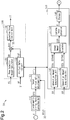
- a processing routine performed by the target air-fuel ratio adjustment unit 120 in the learning control will now be described with reference to Fig. 3 .
- This processing routine is repeatedly performed during execution of the learning control.
- the target air-fuel ratio adjustment unit 120 determines whether a lean period flag FLG1 is set ON.
- the lean period flag FLG1 is a flag for determining whether to permit execution of the lean period process or the rich period process. Specifically, when the lean period flag FLG1 is set ON, execution of the lean period process is permitted. Further, when the lean period flag FLG1 is set OFF, execution of the rich period process is permitted. When initiating the learning control, the lean period flag FLG1 is set ON.
- step S11 when the lean period flag FLG1 is set ON (YES), the target air-fuel ratio adjustment unit 120 proceeds to step S12.
- step S12 the target air-fuel ratio adjustment unit 120 executes the lean period process. Specifically, during the lean period process, the target air-fuel ratio AFTr is calculated by adding a specified changed value Z to the stoichiometric air-fuel ratio AFS. Thus, the target air-fuel ratio AFTr is a leaner value than the stoichiometric air-fuel ratio AFS. Subsequently, in step S13, the target air-fuel ratio adjustment unit 120 determines whether the exhaust air-fuel ratio AFEX is a leaner value than a lean determination value AFLTh.
- the lean determination value AFLTh is set to a leaner value than the base stoichiometric air-fuel ratio AFSB.
- the catalyst 22 is unable to absorb more oxygen.
- step S13 when the exhaust air-fuel ratio AFEX is not a leaner value than the lean determination value AFLTh (NO), the target air-fuel ratio adjustment unit 120 temporarily ends the present processing routine. In this case, the target air-fuel ratio adjustment unit 120 continues the lean period process.
- the target air-fuel ratio adjustment unit 120 proceeds to step S14.
- step S14 the lean period flag FLG1 is set OFF. Then, the target air-fuel ratio adjustment unit 120 temporarily ends the present processing routine.
- step S11 the target air-fuel ratio adjustment unit 120 proceeds to step S15.
- step S15 the rich period process is performed. That is, when the lean period flag FLG1 is switched from ON to OFF, the lean period process is switched to the rich period process.
- the target air-fuel ratio adjustment unit 120 calculates the target air-fuel ratio AFTr by subtracting the changed value Z from the stoichiometric air-fuel ratio AFS.
- the target air-fuel ratio AFTr is a richer value than the stoichiometric air-fuel ratio AFS.
- the target air-fuel ratio adjustment unit 120 determines whether the exhaust air-fuel ratio AFEX is a richer value than a rich determination value AFRTh.
- the rich determination value AFRTh is set to a richer value than the base stoichiometric air-fuel ratio AFSB.
- the catalyst 22 already has no adsorbed oxygen. Accordingly, the exhaust purification device 21 is unable to oxidize (burn) unburned fuel. As a result, unburned fuel flows downstream from the catalyst 22 in the exhaust passage 20.
- step S16 when the exhaust air-fuel ratio AFEX is not a richer value than the rich determination value AFRTh (NO), the target air-fuel ratio adjustment unit 120 temporarily ends the present processing routine. In this case, oxygen still remains adsorbed in the catalyst 22 in the catalyst 22 until the rich period process is started. Thus, the rich period process is continued.
- the target air-fuel ratio adjustment unit 120 proceeds to step S17.
- step S17 the lean period flag FLG1 is set ON. Then, the target air-fuel ratio adjustment unit 120 temporarily ends the present processing routine.
- the lean period flag FLG1 is switched from OFF to ON in this manner, the rich period process is switched to the lean period process.
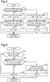
- a processing routine performed by the adsorption amount acquisition unit 141 when calculating the oxygen adsorption amount OSA will now be described with reference to Fig. 4 .
- This processing routine is repeatedly performed during execution of the learning control.
- step S21 of the present processing routine the adsorption amount acquisition unit 141 determines whether the target air-fuel ratio adjustment unit 120 is performing the rich period process.
- the adsorption amount acquisition unit 141 determines that the rich period process is being performed (S21: YES)
- the amount of oxygen adsorbed in the catalyst 22 will not increase.
- the adsorption amount acquisition unit 141 temporarily ends the present processing routine.
- the adsorption amount acquisition unit 141 proceeds to step S22.
- step S22 the adsorption amount acquisition unit 141 determines whether the process performed by the target air-fuel ratio adjustment unit 120 is a process performed immediately after switching from the rich period process to the lean period process.
- the process performed by the target air-fuel ratio adjustment unit 120 is a process performed immediately after switching from the rich period process to the lean period process.
- the process performed by the target air-fuel ratio adjustment unit 120 is a process that is not immediately after switching from the rich period process to the lean period process.
- step S23 the oxygen adsorption amount OSA is substituted into an oxygen adsorption amount hold value OSAH. Specifically, the oxygen adsorption amount hold value OSAH becomes the same value as the oxygen adsorption amount OSA acquired during the preceding lean period process. Subsequently, in step S24, the oxygen adsorption amount OSA is reset to "0". Then, the adsorption amount acquisition unit 141 temporarily ends the present processing routine.
- step S25 the adsorption amount acquisition unit 141 calculates the oxygen adsorption amount OSA. Specifically, the adsorption amount acquisition unit 141 calculates a unit increase amount ⁇ OSA, which is an increase amount of the oxygen adsorption amount per unit time, and calculates an integrated value of the unit increase amount ⁇ OSA as the oxygen adsorption amount OSA.
- the unit increase amount ⁇ OSA increases as the difference of the air-fuel ratio detection value AF and the stoichiometric air-fuel ratio AFS, or the above-described changed value Z, increases.
- the unit increase amount ⁇ OSA increases as the intake air amount GA increases.
- the adsorption amount acquisition unit 141 calculates the unit increase amount ⁇ OSA from the following equation (Equation 2).
- the adsorption amount acquisition unit 141 When the oxygen adsorption amount OSA is calculated in step S25, the adsorption amount acquisition unit 141 then temporarily ends the present processing routine.
- a processing routine performed by the desorption amount acquisition unit 142 when calculating the oxygen desorption amount OED will now be described with reference to Fig. 5 .
- This processing routine is repeatedly executed during execution of the learning control.
- step S31 of the present processing routine the desorption amount acquisition unit 142 determines whether the target air-fuel ratio adjustment unit 120 is performing the lean period process.
- the desorption amount acquisition unit 142 determines that the lean period process is being performed (S31: YES)
- oxygen is not desorbed from the catalyst 22.
- the desorption amount acquisition unit 142 temporarily ends the present processing routine.
- the desorption amount acquisition unit 142 determines that the lean period process is not being performed (S31: NO)
- the desorption amount acquisition unit 142 proceeds to step S32.
- step S32 the desorption amount acquisition unit 142 determines whether the process performed by the target air-fuel ratio adjustment unit 120 is a process performed immediately after switching from the lean period process to the rich period process.
- the lean period process When the lean period process was performed in the preceding processing routine and the rich period process is being performed in the present processing routine, the lean period process has just been switched to the rich period process.
- the rich period process was performed in the preceding processing routine and the rich period process is also being performed in the present processing routine, the lean period process has not just been switched to the rich period process.
- step S33 the oxygen desorption amount OED is substituted into an oxygen desorption amount hold value OEDH. Specifically, the oxygen desorption amount hold value OEDH becomes the same value as the oxygen desorption amount OED acquired during the preceding rich period process.
- step S34 the desorption amount acquisition unit 142 resets the oxygen desorption amount OED to "0". Then, the desorption amount acquisition unit 142 temporarily ends the present processing routine.
- step S35 the desorption amount acquisition unit 142 calculates the oxygen desorption amount OED. Specifically, the desorption amount acquisition unit 142 calculates a unit desorption amount ⁇ OED, which is the amount of oxygen desorbed from the catalyst 22 per unit time. The desorption amount acquisition unit 142 also calculates an integrated value of the unit desorption amount ⁇ OED as the oxygen desorption amount OED.
- the unit desorption amount ⁇ OED increases as the difference of the air-fuel ratio detection value AF and the stoichiometric air-fuel ratio AFS, or the above-described changed value Z, increases.
- the unit desorption amount ⁇ OED increases as the fuel injection amount increases.
- the fuel injection amount is correlated with the intake air amount GA.
- the unit desorption amount ⁇ OED increases as the intake air amount GA increases.
- the desorption amount acquisition unit 142 temporarily ends the present processing routine.
- the oxygen amount deviation DOA is calculated when the oxygen desorption amount hold value OEDH is updated in step S33 and the oxygen desorption amount OED is reset to "0" in step S34.
- the oxygen amount deviation DOA is calculated by subtracting the oxygen adsorption amount OSA from the oxygen desorption amount hold value OEDH.
- the oxygen amount deviation DOA is calculated when the oxygen adsorption amount hold value OSAH is updated in step S23 and the oxygen adsorption amount OSA is reset to "0" in step S24.
- the oxygen amount deviation DOA is calculated by subtracting the oxygen adsorption amount hold value OSAH from the oxygen desorption amount OED.
- a processing routine performed by the learning value calculator 144 to update the learning value X will now be described with reference to Fig. 6 .
- This processing routine is repeatedly performed during execution of the learning control.
- step S41 of the present processing routine the learning value calculator 144 determines whether the process performed by the target air-fuel ratio adjustment unit 120 has been switched from the lean period process to the rich period process.
- the lean period process was performed during the preceding processing routine and the rich period process is being performed during the present processing routine, the lean period process has been switched to the rich period process.
- the learning value calculator 144 determines that the lean period process has been switched to the rich period process (S41: YES)
- the process proceeds to step S42.
- step S42 the learning value calculator 144 determines whether an absolute value of the oxygen amount deviation DOA calculated by the oxygen amount deviation calculator 143 when the lean period process is switched to the rich period process is greater than or equal to a determination value DOATh.
- the determination value DOATh is a reference for determining whether to extensively update the learning value X.
- step S42 when the absolute value of the oxygen amount deviation DOA is greater than or equal to the determination value DOATh (YES), the learning value calculator 144 proceeds to step S44, which will be described later. In this case, the learning value calculator 144 updates the learning value X.
- the learning value calculator 144 temporarily ends the present processing routine. In this case, the learning value X is not updated. That is, when the lean period process is switched to the rich period process, the learning value X is updated as long as the absolute value of the oxygen amount deviation DOA is greater than or equal to the determination value DOATh.
- step S43 the learning value calculator 144 determines whether the process performed by the target air-fuel ratio adjustment unit 120 has been switched from the rich period process to the lean period process.
- the rich period process was performed during the preceding processing routine and the lean period process is being performed during the present processing routine, the rich period process has been switched to the lean period process.
- the learning value calculator 144 determines that the rich period process has been switched to the lean period process (S43: YES)
- the learning value calculator 144 proceeds to step S44.
- the learning value X is updated regardless of the oxygen amount deviation DOA calculated when the rich period process is switched to the lean period process.
- the learning value calculator 144 determines that the rich period process is not is switched to the lean period process (S43: NO)
- the learning value calculator 144 temporarily ends the present processing routine.
- step S44 the learning value calculator 144 updates the learning value X is based on the oxygen amount deviation DOA.
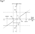
- a learning update value DX is acquired based on the oxygen amount deviation DOA, and the sum of the learning value X and the learning update value DX is calculated as a new learning value X.
- the learning update value DX is acquired using the map shown in Fig. 7 .
- the solid lines shown in Fig. 7 indicate the map used for acquiring the learning update value DX based on the oxygen amount deviation DOA.
- the broken lines L1 shown in Fig. 7 indicate the product of the oxygen amount deviation DOA and a coefficient ⁇ .
- the coefficient ⁇ is a coefficient used for converting the oxygen amount deviation DOA into the learning update value DX.
- the learning dead zone DZ corresponds to a range of the oxygen amount deviation DOA in which the absolute value of the oxygen amount deviation DOA is small so that it can be determined that the learning value X does not have to be updated.
- the learning dead zone DZ has an upper limit DZU that is greater than "0" and a lower limit DZL that is smaller than "0".
- the learning update value DX becomes equal to the smaller one of a specified value DX1 and the product of the oxygen amount deviation DOA and the coefficient ⁇ .
- the learning update value DX is equal to the larger one of the product of the oxygen amount deviation DOA and the coefficient ⁇ and the product of the specified value DX1 and "-1".
- the specified value DX1 is set so that the specified value DX1 is the same as the absolute value of the product of the oxygen amount deviation DOA, which is obtained when the absolute value of the oxygen amount deviation DOA is equal to the determination value DOATh, and the coefficient ⁇ .
- the absolute value of the learning update value DX when the absolute value of the oxygen amount deviation DOA is greater than or equal to the determination value DOATh, the absolute value of the learning update value DX, which is a single update amount of the learning value X, corresponds to the specified value DX1.
- the absolute value of the oxygen amount deviation DOA is less than the determination value DOATh, the absolute value of the learning update value DX, which is a single update amount of the learning value X, is decreased as the absolute value of the oxygen amount deviation DOA decreases.
- the learning value calculator 144 when the learning value calculator 144 completes the updating of the learning value X in step S44, the learning value calculator 144 temporarily ends the present processing routine.
- the updating of the learning value X ends when the oxygen amount deviation DOA is converged in the learning dead zone DZ. Specifically, the updating of the learning value X ends when a state in which the oxygen amount deviation DOA is included in the learning dead zone DZ continues for an end determination time or longer. When the updating of the learning value X ends in this manner, the execution of the learning control ends. Even when the learning control ends, the compensation control is continued.
- Fig. 8 illustrates an example in which the air-fuel ratio detection value AF is deviated toward the rich side from the actual air-fuel ratio AFR.
- the target air-fuel ratio AFTr is a leaner value than the stoichiometric air-fuel ratio AFS, and the catalyst 22 adsorbs oxygen from the exhaust.
- the oxygen adsorption amount OSA is acquired.
- the oxygen desorption amount OED is maintained at the value obtained during the preceding rich period process.
- the exhaust air-fuel ratio AFEX detected by the downstream side air-fuel ratio sensor 32 is equal to the stoichiometric air-fuel ratio.
- the catalyst 22 is unable to adsorb oxygen from the exhaust, which is discharged from the combustion chamber 13 into the exhaust passage 20. This increases the amount of oxygen passing through the catalyst 22.
- the exhaust air-fuel ratio AFEX becomes a leaner value than the stoichiometric air-fuel ratio.
- the lean period process ends and the rich period process is started. Further, at timing t11, the oxygen amount deviation DOA is calculated by subtracting the oxygen adsorption amount OSA acquired during the lean period process, which is performed until timing t11, from the oxygen desorption amount OED, which is the oxygen desorption amount hold value OEDH acquired during the preceding rich period process. In this case, the absolute value of the oxygen amount deviation DOA is greater than the determination value DOATh. Thus, the learning value X is updated even during transition from the lean period process to the rich period process.
- the learning value X is a value for correcting the stoichiometric air-fuel ratio AFS.
- the stoichiometric air-fuel ratio AFS is also updated. Accordingly, after the stoichiometric air-fuel ratio AFS is updated, the air-fuel ratio control is executed using the target air-fuel ratio AFTr based on the updated stoichiometric air-fuel ratio AFS.
- the rich period process is performed.
- the target air-fuel ratio AFTr is a richer value than the stoichiometric air-fuel ratio AFS.
- oxidation (burning) of unburned fuel included in the exhaust discharged from the combustion chamber 13 to the exhaust passage 20 decreases the amount of oxygen absorbed in the catalyst 22.
- the oxygen desorption amount OED is acquired during the rich period process.
- the oxygen adsorption amount OSA is maintained at the value obtained at timing t11.
- the exhaust air-fuel ratio AFEX detected by the downstream side air-fuel ratio sensor 32 becomes equal to the stoichiometric air-fuel ratio.
- the exhaust purification device 21 cannot oxidize unburned fuel included in the exhaust discharged into the exhaust passage 20 from the combustion chamber 13.
- unburned fuel flows through the downstream side of the catalyst 22 in the exhaust passage 20. Accordingly, the exhaust air-fuel ratio AFEX becomes a richer value than the stoichiometric air-fuel ratio.
- the rich period process ends and the lean period process is started.
- the oxygen amount deviation DOA is calculated by subtracting the oxygen adsorption amount hold value OSAH, which is the oxygen adsorption amount OSA acquired during the preceding lean period process, from the oxygen desorption amount OED acquired during the rich period process, which is performed until timing t12.
- the oxygen amount deviation DOA is a value outside the learning dead zone DZ shown in Fig. 7 .
- the learning value X is updated during transition from the rich period process to the lean period process.
- the stoichiometric air-fuel ratio AFS is also updated. Then, the air-fuel ratio control is executed using the target air-fuel ratio AFTr based on the corrected stoichiometric air-fuel ratio AFS. This corrects the deviation between the oxygen desorption amount OED and the oxygen adsorption amount OSA.
- the learning value X is updated in both cases where the rich period process is switched to the lean period process and where the lean period process is switched to the rich period process.
- the learning value X can be updated more frequently than when the learning value X is only updated when the rich period process is switched to the lean period process or when the lean period process is switched to the rich period process.
- Such an increase in the updating frequency of the learning value X shortens the time required to complete update of the learning value X.
- the second stoichiometric air-fuel ratio will be a value that differs from the first stoichiometric air-fuel ratio if the learning value X is updated whenever the process performed by the target air-fuel ratio adjustment unit 120 is switched.
- the calculation will not have a high degree of accuracy.
- the absolute value of the oxygen amount deviation DOA is greater than or equal to the determination value DOATh, the learning update value DX is set so that the absolute value becomes equal to the specified value DX1.
- the low degree of accuracy of the calculation of the oxygen amount deviation DOA will subtly affect the updating accuracy of the learning value X.
- the absolute value of the oxygen amount deviation DOA will be decreased. Further, even when the lean period process is switched to the rich period process, the absolute value of the oxygen amount deviation DOA may not be greater than or equal to the determination value DOATh, for example, like at timing t13. When the absolute value of the oxygen amount deviation DOA is less than the determination value DOATh, it can be determined that the update of the learning value X has somewhat progressed. Thus, the learning value X will not be updated even when the lean period process is switched to the rich period process. That is, the learning value X is updated only when the rich period process is switched to the lean period process.
- the stoichiometric air-fuel ratio AFS which is obtained when acquiring the oxygen adsorption amount OSA used to calculate the oxygen amount deviation DOA, becomes equal to the stoichiometric air-fuel ratio AFS, which is obtained when acquiring the oxygen desorption amount OED used to calculate the oxygen amount deviation DOA.
- the degree of calculation accuracy of the oxygen amount deviation DOA will not decreased.
- the learning update value DX is acquired using such oxygen amount deviation DOA. This prevents the absolute value of the learning update value DX from becoming overly large. That is, hunting of the learning value X will be reduced.
- the learning control may be executed when the air-fuel ratio detection value AF is deviated toward the lean side from the actual air-fuel ratio AFR.
- the learning value X is updated in both cases where the rich period process is switched to the lean period process and where the lean period process is switched to the rich period process.
- the absolute value of the oxygen amount deviation DOA is gradually decreased.
- the learning value X is updated when the rich period process is switched to the lean period process, and the learning value X is not updated when the lean period process is switched to the rich period process. Therefore, even when the air-fuel ratio detection value AF is deviated toward the lean side from the actual air-fuel ratio AFR, the same advantage is obtained as when the air-fuel ratio detection value AF is deviated toward the rich side from the actual air-fuel ratio AFR.
- the present embodiment further obtains the following advantages.
- the learning value X may be updated when the lean period process is switched to the rich period process, and the learning value X does not have to be updated when the rich period process is switched to the lean period process.
- Fig. 9 illustrates a processing routine performed by the learning value calculator 144 in this case.
- step S51 of the present processing routine the learning value calculator 144 determines whether the process performed by the target air-fuel ratio adjustment unit 120 has been switched from the rich period process to the lean period process.
- the learning value calculator 144 proceeds to step S52.
- step S52 the learning value calculator 144 determines whether the absolute value of the oxygen amount deviation DOA calculated when the rich period process is switched to the lean period process is greater than or equal to the determination value DOATh.
- the process proceeds to step S54, which will be described later. In this case, the learning value X is updated.
- the learning value calculator 144 When the absolute value of the oxygen amount deviation DOA is less than the determination value DOATh (S52: NO), the learning value calculator 144 temporarily ends the present processing routine. That is, when the rich period process is switched to the lean period process, the learning value calculator 144 updates the learning value X as long as the absolute value of the oxygen amount deviation DOA is greater than or equal to the determination value DOATh.
- step S51 when the learning value calculator 144 determines that the rich period process has not been switched to the lean period process (NO), the learning value calculator 144 proceeds to step S53.
- step S53 the learning value calculator 144 determines whether the process performed by the target air-fuel ratio adjustment unit 120 has been switched from the lean period process to the rich period process.
- the process proceeds to step S54. That is, the learning value X is updated regardless of the oxygen amount deviation DOA calculated when the lean period process is switched to the rich period process.
- the learning value calculator 144 determines that the lean period process is not switched to the rich period process (S53: NO)
- the learning value calculator 144 temporarily ends the present processing routine.
- step S54 the learning value calculator 144 updates the learning value X in the same manner as in step S44. This temporarily ends the present processing routine.
- the lean period process may be switched to the rich period process under a condition that differs from the condition described in the above embodiment.
- the target air-fuel ratio adjustment unit 120 may end the rich period process and start the lean period process under a condition in which the oxygen adsorption amount OSA acquired by the adsorption amount acquisition unit 141 has reached a specified adsorption amount OSATh.
- the target air-fuel ratio adjustment unit 120 may end the lean period process and start the rich period process under a condition in which the lean period process has continued for a specified lean period process continuation time.
- the condition for switching the rich period process to the lean period process may differ from the condition described in the above embodiment.
- the target air-fuel ratio adjustment unit 120 may end the rich period process and start the lean period process under a condition in which the oxygen desorption amount OED acquired by the desorption amount acquisition unit 142 has reached a specified desorption amount OEDTh.
- the target air-fuel ratio adjustment unit 120 may end the rich period process and start the lean period process under a condition in which the rich period process has continued for a specified rich period process continuation time.
- the deviation amount between the target air-fuel ratio AFTr and the stoichiometric air-fuel ratio AFS during the lean period process may differ from the deviation amount between the target air-fuel ratio AFTr and the stoichiometric air-fuel ratio AFS during the rich period process.
- the downstream side air-fuel ratio sensor 32 may be a sensor having characteristics with which the voltage of a signal suddenly changes in the vicinity of the stoichiometric air-fuel ratio.
- the stoichiometric air-fuel ratio AFS is corrected using the learning value X based on the oxygen amount deviation DOA.
- This compensates for the steady deviation between the air-fuel ratio detection value AF and the actual air-fuel ratio AFR.
- the steady deviation may be compensated for by correcting a parameter other than the stoichiometric air-fuel ratio AFS.
- the above-described steady deviation may be compensated for by correcting the required injection amount QBR instead of the stoichiometric air-fuel ratio AFS.
- the oxygen amount deviation DOA is converted into a learning value corresponding to the fuel injection amount.
- the learning update value DX may be acquired without using the specified value DX1. Specifically, in a case where the oxygen amount deviation DOA is greater than the upper limit DZU of the learning dead zone DZ, the learning update value DX may be equal to the product of the oxygen amount deviation DOA and the coefficient ⁇ even when the oxygen amount deviation DOA is greater than or equal to the determination value DOATh. In the same way, in a case where the oxygen amount deviation DOA is less than the lower limit DZL of the learning dead zone DZ, the learning update value DX may be set equal to the product of the oxygen amount deviation DOA and the coefficient ⁇ even when the absolute value of the oxygen amount deviation DOA is greater than or equal to the determination value DOATh.
- the size of the coefficient ⁇ may be changed depending on whether the absolute value of the oxygen amount deviation DOA is greater than or equal to the determination value DOATh.
- the coefficient ⁇ that is obtained when the absolute value of the oxygen amount deviation DOA is less than the determination value DOATh is referred to as a first coefficient ⁇ 1
- the coefficient ⁇ that is obtained when the absolute value of the oxygen amount deviation DOA is greater than or equal the determination value DOATh may be referred to as a second coefficient ⁇ 2 that is smaller than the first coefficient ⁇ 1.
- the specified value DX1 may be set so that the absolute value of the product of the oxygen amount deviation DOA and the coefficient ⁇ , which is obtained when the absolute value of the oxygen amount deviation DOA is equal to the determination value DOATh, is smaller than the specified value DX1.
- the absolute value of the learning update value DX may be equal to the specified value DX1 even when the absolute value of the oxygen amount deviation DOA is smaller than the determination value DOATh.
- the internal combustion engine 10 may include a port injection valve that injects fuel into the intake passage 14 as a fuel injection valve. Further, the internal combustion engine 10 may include both of a direct injection valve that injects the fuel directly into the cylinders 11 and a port injection valve as the fuel injection valves.
- the controller 30 does not have to perform software processing on all processes it executes.
- the controller 30 may include a dedicated hardware circuit (such as application-specific integrated circuit (ASIC)) that performs hardware processing on at least part of the processes executed by software in the present embodiment. That is, the controller 30 may be modified as long as it has any one of the following configurations (a) to (c).
- a plurality of software processing circuits each including a processor and a program storage device and a plurality of dedicated hardware circuits may be provided. That is, the above processes may be executed in any manner as long as the processes are executed by processing circuitry that includes at least one of a set of one or more software processing circuits and a set of one or more dedicated hardware circuits.
Landscapes
- Engineering & Computer Science (AREA)
- Chemical & Material Sciences (AREA)
- Combustion & Propulsion (AREA)
- Mechanical Engineering (AREA)
- General Engineering & Computer Science (AREA)
- Chemical Kinetics & Catalysis (AREA)
- Health & Medical Sciences (AREA)
- Toxicology (AREA)
- Electrical Control Of Air Or Fuel Supplied To Internal-Combustion Engine (AREA)
- Exhaust Gas After Treatment (AREA)
- Combined Controls Of Internal Combustion Engines (AREA)
Applications Claiming Priority (1)
| Application Number | Priority Date | Filing Date | Title |
|---|---|---|---|
| JP2019001820A JP7074076B2 (ja) | 2019-01-09 | 2019-01-09 | 内燃機関の制御装置 |
Publications (2)
| Publication Number | Publication Date |
|---|---|
| EP3680472A1 true EP3680472A1 (de) | 2020-07-15 |
| EP3680472B1 EP3680472B1 (de) | 2025-04-23 |
Family
ID=69143415
Family Applications (1)
| Application Number | Title | Priority Date | Filing Date |
|---|---|---|---|
| EP20150418.0A Active EP3680472B1 (de) | 2019-01-09 | 2020-01-07 | Steuergerät für eine brennkraftmaschine und verfahren zur steuerung einer brennkraftmaschine |
Country Status (4)
| Country | Link |
|---|---|
| US (1) | US10851732B2 (de) |
| EP (1) | EP3680472B1 (de) |
| JP (1) | JP7074076B2 (de) |
| CN (1) | CN111502844B (de) |
Families Citing this family (2)
| Publication number | Priority date | Publication date | Assignee | Title |
|---|---|---|---|---|
| DE102022204003A1 (de) * | 2022-04-26 | 2023-10-26 | Robert Bosch Gesellschaft mit beschränkter Haftung | Vorrichtung und Verfahren zum Bestimmen eines Versatzes auf einem Signal eines Sensors zur Messung von Restsauerstoff |
| JP7722342B2 (ja) * | 2022-12-02 | 2025-08-13 | トヨタ自動車株式会社 | 空燃比制御装置 |
Citations (3)
| Publication number | Priority date | Publication date | Assignee | Title |
|---|---|---|---|---|
| EP1336728A2 (de) * | 2002-02-13 | 2003-08-20 | Robert Bosch Gmbh | Verfahren und Vorrichtung zur Regelung des Kraftstoff/Luft-Verhältnisses eines Verbrennungsprozesses |
| DE102013201734A1 (de) * | 2013-02-04 | 2014-08-07 | Robert Bosch Gmbh | Verfahren zum Betreiben einer Lambdasondenanordnung im Abgassystem einer Brennkraftmaschine |
| WO2015050268A1 (en) * | 2013-10-02 | 2015-04-09 | Toyota Jidosha Kabushiki Kaisha | Control device of internal combustion engine |
Family Cites Families (10)
| Publication number | Priority date | Publication date | Assignee | Title |
|---|---|---|---|---|
| JPH08246925A (ja) * | 1995-03-13 | 1996-09-24 | Fuji Heavy Ind Ltd | エンジンの空燃比制御方法 |
| JP2005098205A (ja) * | 2003-09-25 | 2005-04-14 | Toyota Motor Corp | 内燃機関の空燃比制御装置 |
| JP4487971B2 (ja) * | 2006-04-24 | 2010-06-23 | トヨタ自動車株式会社 | 内燃機関の空燃比制御装置 |
| JP4221026B2 (ja) * | 2006-12-25 | 2009-02-12 | 三菱電機株式会社 | 内燃機関の空燃比制御装置 |
| JP4221025B2 (ja) * | 2006-12-25 | 2009-02-12 | 三菱電機株式会社 | 内燃機関の空燃比制御装置 |
| JP4930722B2 (ja) * | 2007-12-25 | 2012-05-16 | トヨタ自動車株式会社 | 内燃機関の制御装置 |
| CN104956052B (zh) | 2013-01-29 | 2017-07-04 | 丰田自动车株式会社 | 内燃机的控制装置 |
| WO2015105160A1 (ja) * | 2014-01-10 | 2015-07-16 | トヨタ自動車株式会社 | 内燃機関の制御装置 |
| JP6308150B2 (ja) * | 2015-03-12 | 2018-04-11 | トヨタ自動車株式会社 | 内燃機関の排気浄化装置 |
| JP6213540B2 (ja) * | 2015-10-01 | 2017-10-18 | トヨタ自動車株式会社 | 内燃機関の排気浄化装置 |
-
2019
- 2019-01-09 JP JP2019001820A patent/JP7074076B2/ja active Active
- 2019-12-24 CN CN201911344612.1A patent/CN111502844B/zh not_active Expired - Fee Related
-
2020
- 2020-01-02 US US16/732,419 patent/US10851732B2/en not_active Expired - Fee Related
- 2020-01-07 EP EP20150418.0A patent/EP3680472B1/de active Active
Patent Citations (4)
| Publication number | Priority date | Publication date | Assignee | Title |
|---|---|---|---|---|
| EP1336728A2 (de) * | 2002-02-13 | 2003-08-20 | Robert Bosch Gmbh | Verfahren und Vorrichtung zur Regelung des Kraftstoff/Luft-Verhältnisses eines Verbrennungsprozesses |
| DE102013201734A1 (de) * | 2013-02-04 | 2014-08-07 | Robert Bosch Gmbh | Verfahren zum Betreiben einer Lambdasondenanordnung im Abgassystem einer Brennkraftmaschine |
| WO2015050268A1 (en) * | 2013-10-02 | 2015-04-09 | Toyota Jidosha Kabushiki Kaisha | Control device of internal combustion engine |
| JP2015071963A (ja) | 2013-10-02 | 2015-04-16 | トヨタ自動車株式会社 | 内燃機関の制御装置 |
Also Published As
| Publication number | Publication date |
|---|---|
| US20200217264A1 (en) | 2020-07-09 |
| EP3680472B1 (de) | 2025-04-23 |
| JP7074076B2 (ja) | 2022-05-24 |
| US10851732B2 (en) | 2020-12-01 |
| JP2020112057A (ja) | 2020-07-27 |
| CN111502844B (zh) | 2022-06-24 |
| CN111502844A (zh) | 2020-08-07 |
Similar Documents
| Publication | Publication Date | Title |
|---|---|---|
| US9759153B2 (en) | Control apparatus for internal combustion engine | |
| US20190128198A1 (en) | Controller and control method for internal combustion engine | |
| EP1329626A2 (de) | Abgasleck-Diagnose eines Motors | |
| US10961928B2 (en) | Control apparatus for internal combustion engine and method for controlling internal combustion engine | |
| EP3680472B1 (de) | Steuergerät für eine brennkraftmaschine und verfahren zur steuerung einer brennkraftmaschine | |
| US10753298B2 (en) | Controller for internal combustion engine | |
| US9664096B2 (en) | Control apparatus for internal combustion engine | |
| JPH0814083A (ja) | 内燃機関の電子制御装置 | |
| US5762055A (en) | Air-to-fuel ratio control apparatus for an internal combustion engine | |
| KR100240970B1 (ko) | 내연 기관용의 연료 및 공기 혼합물 조성의 제어 방법 | |
| US20180230921A1 (en) | Fuel injection amount control device | |
| US8037671B2 (en) | Method and device for the calibration of an exhaust gas probe, and method and device for the operation of an internal combustion engine | |
| JPH04279748A (ja) | 燃料噴射系の異常診断装置 | |
| JP5983691B2 (ja) | 内燃機関の制御装置 | |
| US10823095B2 (en) | Controller and control method for internal combustion engine | |
| JP7196391B2 (ja) | 内燃機関の制御装置 | |
| US20250109720A1 (en) | Controller for internal combustion engine and method for controlling internal combustion engine | |
| US20260098501A1 (en) | Controller for internal combustion engine | |
| JP2009250164A (ja) | 内燃機関の制御装置 | |
| JP6473094B2 (ja) | 内燃機関の空燃比制御装置及び空燃比制御方法 | |
| JP2600771B2 (ja) | 内燃機関の空燃比制御装置 | |
| JP2023175080A (ja) | 触媒能力検出装置 | |
| JPH03217635A (ja) | エンジンの空燃比制御装置 | |
| JP2019060346A (ja) | 内燃機関の空燃比制御装置及び空燃比制御方法 | |
| JP2009235997A (ja) | 空燃比制御方法 |
Legal Events
| Date | Code | Title | Description |
|---|---|---|---|
| PUAI | Public reference made under article 153(3) epc to a published international application that has entered the european phase |
Free format text: ORIGINAL CODE: 0009012 |
|
| STAA | Information on the status of an ep patent application or granted ep patent |
Free format text: STATUS: REQUEST FOR EXAMINATION WAS MADE |
|
| 17P | Request for examination filed |
Effective date: 20200120 |
|
| AK | Designated contracting states |
Kind code of ref document: A1 Designated state(s): AL AT BE BG CH CY CZ DE DK EE ES FI FR GB GR HR HU IE IS IT LI LT LU LV MC MK MT NL NO PL PT RO RS SE SI SK SM TR |
|
| AX | Request for extension of the european patent |
Extension state: BA ME |
|
| STAA | Information on the status of an ep patent application or granted ep patent |
Free format text: STATUS: EXAMINATION IS IN PROGRESS |
|
| 17Q | First examination report despatched |
Effective date: 20221019 |
|
| GRAP | Despatch of communication of intention to grant a patent |
Free format text: ORIGINAL CODE: EPIDOSNIGR1 |
|
| STAA | Information on the status of an ep patent application or granted ep patent |
Free format text: STATUS: GRANT OF PATENT IS INTENDED |
|
| INTG | Intention to grant announced |
Effective date: 20241202 |
|
| GRAS | Grant fee paid |
Free format text: ORIGINAL CODE: EPIDOSNIGR3 |
|
| GRAA | (expected) grant |
Free format text: ORIGINAL CODE: 0009210 |
|
| STAA | Information on the status of an ep patent application or granted ep patent |
Free format text: STATUS: THE PATENT HAS BEEN GRANTED |
|
| AK | Designated contracting states |
Kind code of ref document: B1 Designated state(s): AL AT BE BG CH CY CZ DE DK EE ES FI FR GB GR HR HU IE IS IT LI LT LU LV MC MK MT NL NO PL PT RO RS SE SI SK SM TR |
|
| REG | Reference to a national code |
Ref country code: GB Ref legal event code: FG4D |
|
| REG | Reference to a national code |
Ref country code: CH Ref legal event code: EP |
|
| REG | Reference to a national code |
Ref country code: DE Ref legal event code: R096 Ref document number: 602020049794 Country of ref document: DE |
|
| REG | Reference to a national code |
Ref country code: IE Ref legal event code: FG4D |
|
| P01 | Opt-out of the competence of the unified patent court (upc) registered |
Free format text: CASE NUMBER: APP_20535/2025 Effective date: 20250430 |
|
| REG | Reference to a national code |
Ref country code: NL Ref legal event code: MP Effective date: 20250423 |
|
| PG25 | Lapsed in a contracting state [announced via postgrant information from national office to epo] |
Ref country code: NL Free format text: LAPSE BECAUSE OF FAILURE TO SUBMIT A TRANSLATION OF THE DESCRIPTION OR TO PAY THE FEE WITHIN THE PRESCRIBED TIME-LIMIT Effective date: 20250423 |
|
| REG | Reference to a national code |
Ref country code: AT Ref legal event code: MK05 Ref document number: 1787955 Country of ref document: AT Kind code of ref document: T Effective date: 20250423 |
|
| REG | Reference to a national code |
Ref country code: DE Ref legal event code: R084 Ref document number: 602020049794 Country of ref document: DE |
|
| PG25 | Lapsed in a contracting state [announced via postgrant information from national office to epo] |
Ref country code: FI Free format text: LAPSE BECAUSE OF FAILURE TO SUBMIT A TRANSLATION OF THE DESCRIPTION OR TO PAY THE FEE WITHIN THE PRESCRIBED TIME-LIMIT Effective date: 20250423 Ref country code: ES Free format text: LAPSE BECAUSE OF FAILURE TO SUBMIT A TRANSLATION OF THE DESCRIPTION OR TO PAY THE FEE WITHIN THE PRESCRIBED TIME-LIMIT Effective date: 20250423 Ref country code: PT Free format text: LAPSE BECAUSE OF FAILURE TO SUBMIT A TRANSLATION OF THE DESCRIPTION OR TO PAY THE FEE WITHIN THE PRESCRIBED TIME-LIMIT Effective date: 20250825 |
|
| REG | Reference to a national code |
Ref country code: LT Ref legal event code: MG9D |
|
| PG25 | Lapsed in a contracting state [announced via postgrant information from national office to epo] |
Ref country code: GR Free format text: LAPSE BECAUSE OF FAILURE TO SUBMIT A TRANSLATION OF THE DESCRIPTION OR TO PAY THE FEE WITHIN THE PRESCRIBED TIME-LIMIT Effective date: 20250724 Ref country code: NO Free format text: LAPSE BECAUSE OF FAILURE TO SUBMIT A TRANSLATION OF THE DESCRIPTION OR TO PAY THE FEE WITHIN THE PRESCRIBED TIME-LIMIT Effective date: 20250723 |
|
| PG25 | Lapsed in a contracting state [announced via postgrant information from national office to epo] |
Ref country code: PL Free format text: LAPSE BECAUSE OF FAILURE TO SUBMIT A TRANSLATION OF THE DESCRIPTION OR TO PAY THE FEE WITHIN THE PRESCRIBED TIME-LIMIT Effective date: 20250423 |
|
| PG25 | Lapsed in a contracting state [announced via postgrant information from national office to epo] |
Ref country code: BG Free format text: LAPSE BECAUSE OF FAILURE TO SUBMIT A TRANSLATION OF THE DESCRIPTION OR TO PAY THE FEE WITHIN THE PRESCRIBED TIME-LIMIT Effective date: 20250423 |
|
| PG25 | Lapsed in a contracting state [announced via postgrant information from national office to epo] |
Ref country code: HR Free format text: LAPSE BECAUSE OF FAILURE TO SUBMIT A TRANSLATION OF THE DESCRIPTION OR TO PAY THE FEE WITHIN THE PRESCRIBED TIME-LIMIT Effective date: 20250423 |
|
| PG25 | Lapsed in a contracting state [announced via postgrant information from national office to epo] |
Ref country code: AT Free format text: LAPSE BECAUSE OF FAILURE TO SUBMIT A TRANSLATION OF THE DESCRIPTION OR TO PAY THE FEE WITHIN THE PRESCRIBED TIME-LIMIT Effective date: 20250423 |
|
| PG25 | Lapsed in a contracting state [announced via postgrant information from national office to epo] |
Ref country code: RS Free format text: LAPSE BECAUSE OF FAILURE TO SUBMIT A TRANSLATION OF THE DESCRIPTION OR TO PAY THE FEE WITHIN THE PRESCRIBED TIME-LIMIT Effective date: 20250723 |
|
| PG25 | Lapsed in a contracting state [announced via postgrant information from national office to epo] |
Ref country code: IS Free format text: LAPSE BECAUSE OF FAILURE TO SUBMIT A TRANSLATION OF THE DESCRIPTION OR TO PAY THE FEE WITHIN THE PRESCRIBED TIME-LIMIT Effective date: 20250823 |
|
| PG25 | Lapsed in a contracting state [announced via postgrant information from national office to epo] |
Ref country code: LV Free format text: LAPSE BECAUSE OF FAILURE TO SUBMIT A TRANSLATION OF THE DESCRIPTION OR TO PAY THE FEE WITHIN THE PRESCRIBED TIME-LIMIT Effective date: 20250423 |
|
| PGFP | Annual fee paid to national office [announced via postgrant information from national office to epo] |
Ref country code: GB Payment date: 20251127 Year of fee payment: 7 |
|
| PG25 | Lapsed in a contracting state [announced via postgrant information from national office to epo] |
Ref country code: SM Free format text: LAPSE BECAUSE OF FAILURE TO SUBMIT A TRANSLATION OF THE DESCRIPTION OR TO PAY THE FEE WITHIN THE PRESCRIBED TIME-LIMIT Effective date: 20250423 Ref country code: DK Free format text: LAPSE BECAUSE OF FAILURE TO SUBMIT A TRANSLATION OF THE DESCRIPTION OR TO PAY THE FEE WITHIN THE PRESCRIBED TIME-LIMIT Effective date: 20250423 |
|
| PGFP | Annual fee paid to national office [announced via postgrant information from national office to epo] |
Ref country code: FR Payment date: 20251128 Year of fee payment: 7 |
|
| PG25 | Lapsed in a contracting state [announced via postgrant information from national office to epo] |
Ref country code: CZ Free format text: LAPSE BECAUSE OF FAILURE TO SUBMIT A TRANSLATION OF THE DESCRIPTION OR TO PAY THE FEE WITHIN THE PRESCRIBED TIME-LIMIT Effective date: 20250423 |
|
| PG25 | Lapsed in a contracting state [announced via postgrant information from national office to epo] |
Ref country code: EE Free format text: LAPSE BECAUSE OF FAILURE TO SUBMIT A TRANSLATION OF THE DESCRIPTION OR TO PAY THE FEE WITHIN THE PRESCRIBED TIME-LIMIT Effective date: 20250423 |
|
| REG | Reference to a national code |
Ref country code: DE Ref legal event code: R097 Ref document number: 602020049794 Country of ref document: DE |
|
| PG25 | Lapsed in a contracting state [announced via postgrant information from national office to epo] |
Ref country code: RO Free format text: LAPSE BECAUSE OF FAILURE TO SUBMIT A TRANSLATION OF THE DESCRIPTION OR TO PAY THE FEE WITHIN THE PRESCRIBED TIME-LIMIT Effective date: 20250423 Ref country code: SK Free format text: LAPSE BECAUSE OF FAILURE TO SUBMIT A TRANSLATION OF THE DESCRIPTION OR TO PAY THE FEE WITHIN THE PRESCRIBED TIME-LIMIT Effective date: 20250423 |
|
| PG25 | Lapsed in a contracting state [announced via postgrant information from national office to epo] |
Ref country code: IT Free format text: LAPSE BECAUSE OF FAILURE TO SUBMIT A TRANSLATION OF THE DESCRIPTION OR TO PAY THE FEE WITHIN THE PRESCRIBED TIME-LIMIT Effective date: 20250423 |
|
| REG | Reference to a national code |
Ref country code: GB Ref legal event code: 746 Effective date: 20260106 |
|
| PLBE | No opposition filed within time limit |
Free format text: ORIGINAL CODE: 0009261 |
|
| STAA | Information on the status of an ep patent application or granted ep patent |
Free format text: STATUS: NO OPPOSITION FILED WITHIN TIME LIMIT |
|
| REG | Reference to a national code |
Ref country code: CH Ref legal event code: L10 Free format text: ST27 STATUS EVENT CODE: U-0-0-L10-L00 (AS PROVIDED BY THE NATIONAL OFFICE) Effective date: 20260304 |
|
| 26N | No opposition filed |
Effective date: 20260126 |
|
| PGFP | Annual fee paid to national office [announced via postgrant information from national office to epo] |
Ref country code: DE Payment date: 20251203 Year of fee payment: 7 |