EP3680501B1 - Ensembles de bague de retenue - Google Patents
Ensembles de bague de retenue Download PDFInfo
- Publication number
- EP3680501B1 EP3680501B1 EP19212834.6A EP19212834A EP3680501B1 EP 3680501 B1 EP3680501 B1 EP 3680501B1 EP 19212834 A EP19212834 A EP 19212834A EP 3680501 B1 EP3680501 B1 EP 3680501B1
- Authority
- EP
- European Patent Office
- Prior art keywords
- shaft
- retaining ring
- flat
- sleeve
- slot
- Prior art date
- Legal status (The legal status is an assumption and is not a legal conclusion. Google has not performed a legal analysis and makes no representation as to the accuracy of the status listed.)
- Active
Links
Images



Classifications
-
- F—MECHANICAL ENGINEERING; LIGHTING; HEATING; WEAPONS; BLASTING
- F16—ENGINEERING ELEMENTS AND UNITS; GENERAL MEASURES FOR PRODUCING AND MAINTAINING EFFECTIVE FUNCTIONING OF MACHINES OR INSTALLATIONS; THERMAL INSULATION IN GENERAL
- F16D—COUPLINGS FOR TRANSMITTING ROTATION; CLUTCHES; BRAKES
- F16D1/00—Couplings for rigidly connecting two coaxial shafts or other movable machine elements
- F16D1/10—Quick-acting couplings in which the parts are connected by simply bringing them together axially
- F16D1/108—Quick-acting couplings in which the parts are connected by simply bringing them together axially having retaining means rotating with the coupling and acting by interengaging parts, i.e. positive coupling
-
- F—MECHANICAL ENGINEERING; LIGHTING; HEATING; WEAPONS; BLASTING
- F16—ENGINEERING ELEMENTS AND UNITS; GENERAL MEASURES FOR PRODUCING AND MAINTAINING EFFECTIVE FUNCTIONING OF MACHINES OR INSTALLATIONS; THERMAL INSULATION IN GENERAL
- F16C—SHAFTS; FLEXIBLE SHAFTS; ELEMENTS OR CRANKSHAFT MECHANISMS; ROTARY BODIES OTHER THAN GEARING ELEMENTS; BEARINGS
- F16C35/00—Rigid support of bearing units; Housings, e.g. caps, covers
- F16C35/02—Rigid support of bearing units; Housings, e.g. caps, covers in the case of sliding-contact bearings
-
- F—MECHANICAL ENGINEERING; LIGHTING; HEATING; WEAPONS; BLASTING
- F16—ENGINEERING ELEMENTS AND UNITS; GENERAL MEASURES FOR PRODUCING AND MAINTAINING EFFECTIVE FUNCTIONING OF MACHINES OR INSTALLATIONS; THERMAL INSULATION IN GENERAL
- F16B—DEVICES FOR FASTENING OR SECURING CONSTRUCTIONAL ELEMENTS OR MACHINE PARTS TOGETHER, e.g. NAILS, BOLTS, CIRCLIPS, CLAMPS, CLIPS OR WEDGES; JOINTS OR JOINTING
- F16B21/00—Means for preventing relative axial movement of a pin, spigot, shaft or the like and a member surrounding it; Stud-and-socket releasable fastenings
- F16B21/10—Means for preventing relative axial movement of a pin, spigot, shaft or the like and a member surrounding it; Stud-and-socket releasable fastenings by separate parts
- F16B21/16—Means for preventing relative axial movement of a pin, spigot, shaft or the like and a member surrounding it; Stud-and-socket releasable fastenings by separate parts with grooves or notches in the pin or shaft
- F16B21/18—Means for preventing relative axial movement of a pin, spigot, shaft or the like and a member surrounding it; Stud-and-socket releasable fastenings by separate parts with grooves or notches in the pin or shaft with circlips or like resilient retaining devices, i.e. resilient in the plane of the ring or the like; Details
- F16B21/186—Means for preventing relative axial movement of a pin, spigot, shaft or the like and a member surrounding it; Stud-and-socket releasable fastenings by separate parts with grooves or notches in the pin or shaft with circlips or like resilient retaining devices, i.e. resilient in the plane of the ring or the like; Details external, i.e. with contracting action
-
- F—MECHANICAL ENGINEERING; LIGHTING; HEATING; WEAPONS; BLASTING
- F16—ENGINEERING ELEMENTS AND UNITS; GENERAL MEASURES FOR PRODUCING AND MAINTAINING EFFECTIVE FUNCTIONING OF MACHINES OR INSTALLATIONS; THERMAL INSULATION IN GENERAL
- F16C—SHAFTS; FLEXIBLE SHAFTS; ELEMENTS OR CRANKSHAFT MECHANISMS; ROTARY BODIES OTHER THAN GEARING ELEMENTS; BEARINGS
- F16C35/00—Rigid support of bearing units; Housings, e.g. caps, covers
- F16C35/04—Rigid support of bearing units; Housings, e.g. caps, covers in the case of ball or roller bearings
- F16C35/06—Mounting or dismounting of ball or roller bearings; Fixing them onto shaft or in housing
- F16C35/07—Fixing them on the shaft or housing with interposition of an element
- F16C35/073—Fixing them on the shaft or housing with interposition of an element between shaft and inner race ring
-
- F—MECHANICAL ENGINEERING; LIGHTING; HEATING; WEAPONS; BLASTING
- F16—ENGINEERING ELEMENTS AND UNITS; GENERAL MEASURES FOR PRODUCING AND MAINTAINING EFFECTIVE FUNCTIONING OF MACHINES OR INSTALLATIONS; THERMAL INSULATION IN GENERAL
- F16B—DEVICES FOR FASTENING OR SECURING CONSTRUCTIONAL ELEMENTS OR MACHINE PARTS TOGETHER, e.g. NAILS, BOLTS, CIRCLIPS, CLAMPS, CLIPS OR WEDGES; JOINTS OR JOINTING
- F16B21/00—Means for preventing relative axial movement of a pin, spigot, shaft or the like and a member surrounding it; Stud-and-socket releasable fastenings
- F16B21/10—Means for preventing relative axial movement of a pin, spigot, shaft or the like and a member surrounding it; Stud-and-socket releasable fastenings by separate parts
- F16B21/16—Means for preventing relative axial movement of a pin, spigot, shaft or the like and a member surrounding it; Stud-and-socket releasable fastenings by separate parts with grooves or notches in the pin or shaft
- F16B21/18—Means for preventing relative axial movement of a pin, spigot, shaft or the like and a member surrounding it; Stud-and-socket releasable fastenings by separate parts with grooves or notches in the pin or shaft with circlips or like resilient retaining devices, i.e. resilient in the plane of the ring or the like; Details
- F16B21/183—Means for preventing relative axial movement of a pin, spigot, shaft or the like and a member surrounding it; Stud-and-socket releasable fastenings by separate parts with grooves or notches in the pin or shaft with circlips or like resilient retaining devices, i.e. resilient in the plane of the ring or the like; Details internal, i.e. with spreading action
-
- F—MECHANICAL ENGINEERING; LIGHTING; HEATING; WEAPONS; BLASTING
- F16—ENGINEERING ELEMENTS AND UNITS; GENERAL MEASURES FOR PRODUCING AND MAINTAINING EFFECTIVE FUNCTIONING OF MACHINES OR INSTALLATIONS; THERMAL INSULATION IN GENERAL
- F16C—SHAFTS; FLEXIBLE SHAFTS; ELEMENTS OR CRANKSHAFT MECHANISMS; ROTARY BODIES OTHER THAN GEARING ELEMENTS; BEARINGS
- F16C2226/00—Joining parts; Fastening; Assembling or mounting parts
- F16C2226/50—Positive connections
- F16C2226/70—Positive connections with complementary interlocking parts
-
- F—MECHANICAL ENGINEERING; LIGHTING; HEATING; WEAPONS; BLASTING
- F16—ENGINEERING ELEMENTS AND UNITS; GENERAL MEASURES FOR PRODUCING AND MAINTAINING EFFECTIVE FUNCTIONING OF MACHINES OR INSTALLATIONS; THERMAL INSULATION IN GENERAL
- F16C—SHAFTS; FLEXIBLE SHAFTS; ELEMENTS OR CRANKSHAFT MECHANISMS; ROTARY BODIES OTHER THAN GEARING ELEMENTS; BEARINGS
- F16C2300/00—Application independent of particular apparatuses
- F16C2300/02—General use or purpose, i.e. no use, purpose, special adaptation or modification indicated or a wide variety of uses mentioned
-
- F—MECHANICAL ENGINEERING; LIGHTING; HEATING; WEAPONS; BLASTING
- F16—ENGINEERING ELEMENTS AND UNITS; GENERAL MEASURES FOR PRODUCING AND MAINTAINING EFFECTIVE FUNCTIONING OF MACHINES OR INSTALLATIONS; THERMAL INSULATION IN GENERAL
- F16D—COUPLINGS FOR TRANSMITTING ROTATION; CLUTCHES; BRAKES
- F16D1/00—Couplings for rigidly connecting two coaxial shafts or other movable machine elements
- F16D1/10—Quick-acting couplings in which the parts are connected by simply bringing them together axially
- F16D2001/102—Quick-acting couplings in which the parts are connected by simply bringing them together axially the torque is transmitted via polygon shaped connections
Definitions
- This disclosure relates to retainers, more specifically to retaining ring assemblies.
- a retaining ring configured to retain a shaft to a sleeve to fix the shaft rotationally and axially to the sleeve is defined in claim 1 and includes
- the first portion and the second portion can be identical halves of the retaining ring.
- the first portion and the second portion are connected together such that the first portion and the second portion are free from each other.
- the first portion and the second portion can be made of metal (e.g., steel). Any other suitable material is contemplated herein.
- an edge of the first portion flat and/or second portion flat can be parallel with an edge of each curved section end. Any suitable location or orientation for the flats is contemplated herein. Any other suitable position of the curved sections and the one or more flats are contemplated herein.
- a system can include a shaft having at least one retaining ring slot defined on an outer radius thereof, the retaining ring slot at least including at least one first flat detent, a sleeve comprising a central orifice for receiving the shaft, the sleeve defining at least one inner radius ring interface defining at least one flat section, and a retaining ring retaining the shaft to the sleeve to fix the shaft rotationally and axially to the sleeve.
- the retaining ring can be any suitable retaining ring, e.g., as disclosed above.
- the first portion flat can be disposed flushly in contact with the first detent.
- the second portion flat can be disposed flushly in contact with a second detent of the retaining ring slot.
- the retaining ring slot can be symmetric about the shaft.
- the inner radius ring interface can be symmetric about the central orifice.
- the sleeve can define a clip slot axially forward of the inner radius ring interface and configured to receive a spring clip.
- the system can include a spring clip disposed with the clip slot to axially retain the retaining ring to the sleeve, thereby axially retaining the shaft to the sleeve.
- the shaft and the sleeve form at least a portion of a hydraulic system, wherein a shaft lubricant hole is aligned with a sleeve lubricant hole when the retained together by the retaining ring.
- a method for retaining a shaft to a sleeve includes
- the method includes inserting the shaft having the first portion and second portion thereon into a central orifice of a sleeve such that the first portion and second portion interface with at least one inner radius ring interface defining at least one flat section such that the first portion and the second portion, and consequently the shaft, cannot rotate relative to the sleeve.
- the method can include installing a spring clip into a clip slot that is axially forward of the inner radius ring interface and configured to receive the spring clip to axially retain the retaining ring to the sleeve, thereby axially retaining the shaft to the sleeve.
- FIG. 1 an illustrative view of an embodiment of a retaining ring in accordance with the disclosure is shown in Fig. 1 and is designated generally by reference character 100.
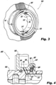
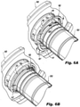
- FIGs. 2-6D Other embodiments and/or aspects of this disclosure are shown in Figs. 2-6D .
- a retaining ring 100 configured to retain a shaft 200 to a sleeve 300 to fix the shaft 200 rotationally and axially to the sleeve 300 can include a first portion 101 configured to install around the shaft 200 and within the sleeve 300.
- the first portion 101 can include one or more first curved sections 103a, 103b and at least one first portion flat 105.
- the retaining ring 100 can include a second portion 107 configured to install around the shaft 200 and moveable relative to the first portion 101.
- the second portion 107 can include one or more second curved sections 109a, 109b and at least one second portion flat 111.
- the one or more first portion flat 105 can be defined between a plurality of the first curved sections 103a, 103b as shown.
- the second portion flat 111 can be defined between a plurality of the second curved sections 109a, 109b, for example. Any other suitable positioning for the one or more flats 105, 111 is contemplated herein.
- first portion 101 and the second portion 107 can be identical halves of the retaining ring 100. In certain embodiments, the first portion 101 and the second portion 107 may not be connected together as shown, such that the first portion 101 and the second portion 107 are free from each other. In certain embodiments, the first portion 101 and the second portion 107 may be hinged (e.g., at one end of each) to each other or otherwise connected or removably connectable to each other.
- the first portion 101 and the second portion 107 can be made of metal (e.g., steel). Any other suitable material is contemplated herein.
- an edge 113 of the first portion flat 105 and/or an edge 115 of the second portion flat 115 can be parallel with an edge 117, 119 of each curved section end. Any suitable location or orientation for the one or more flats 105, 115 is contemplated herein. Any other suitable position of the curved sections 103a, 103b, 109a, 109b and the one or more flats 105, 115 are contemplated herein.
- a system 400 can include a shaft 200 having at least one retaining ring slot 201 defined on an outer radius thereof.
- the retaining ring slot 201 at least includes at least one first flat detent 203 (e.g., one for each first flat 105).
- the shaft can include at least one second flat detent 205 (e.g., one for each second flat 111), e.g., on a diametrically opposite side of the shaft 200.
- the system can include a sleeve 300 comprising a central orifice 301 for receiving the shaft 200.
- the sleeve 300 can define at least one inner radius ring interface 303 defining at least one flat section 305.
- the system 400 can include the retaining ring 100 retaining the shaft 200 to the sleeve 300 to fix the shaft 200 rotationally and axially to the sleeve 300, for example, as shown.
- the retaining ring 100 can be any suitable retaining ring, e.g., as disclosed above.
- the first portion flat 105 can be disposed flushly in contact with the first flat detent 203.
- the second portion flat 111 can be disposed flushly in contact with the second flat detent 205 of the retaining ring slot 201.
- the retaining ring slot 201 can be symmetric about the shaft 200 as shown.
- the inner radius ring interface 303 can be symmetric about the central orifice 301, as shown.
- the sleeve 300 can define a clip slot 307 axially forward of the inner radius ring interface 303, e.g., as shown, and configured to receive a spring clip 309 (e.g., a c-clip, a spiral lock).
- a spring clip 309 e.g., a c-clip, a spiral lock
- the system 400 can include the spring clip 309 disposed within the clip slot 307 to axially retain the retaining ring 100 to the sleeve 300, thereby axially retaining the shaft 200 to the sleeve 300.
- the shaft 300 and the sleeve 200 form at least a portion of a hydraulic system.
- a shaft lubricant hole 215 can be aligned with a sleeve lubricant hole 315 when the retained together by the retaining ring 100.
- a method for retaining a shaft 200 to a sleeve 300 can include installing a first portion 101 of a retaining ring 100 in at least one retaining ring slot 201 defined on an outer radius of a shaft 200.
- the retaining ring slot can at least include at least one first portion flat detent, such that at least one first portion flat of the first portion is flush with the at least one first flat detent.
- the method can include installing a second portion 107 of a retaining ring 100 in at least one of the least one retaining ring slot 201 defined on the outer radius of the shaft 200.
- the retaining ring slot can at least include at least one second portion flat detent, such that at least one second portion flat of the second portion is flush with the at least one first flat detent.
- the method can include inserting the shaft 200 having the first portion and second portion thereon into a central orifice 301 of a sleeve 300 such that the first portion and second portion interface with at least one inner radius ring interface defining at least one flat section such that the first portion and the second portion, and consequently the shaft 200, cannot rotate relative to the sleeve 300.
- the method can include installing a spring clip 309 into a clip slot 307 that is axially forward of the inner radius ring interface and configured to receive the spring clip to axially retain the retaining ring to the sleeve, thereby axially retaining the shaft to the sleeve.
- Certain embodiments disclosed above include a ring that is split into two halves. Each half can include a flat segment. The flats mate with flats in a shaft and an outer sleeve to provide axial and rotational alignment between the shaft and the sleeve. A separate common retaining ring can be installed to prevent axial motion in the opposite direction after assembly to lock the assembly together. Alignment (relative clocked position) can be controlled as a function of flat location on each of the shaft, sleeve, and ring, and can allow for proper positioning of additional features (e.g., lubrication holes).
- additional features e.g., lubrication holes
- Embodiments allow two parts to rotate as one without using more complex/costly features (splines, interference fits). Certain embodiments can only be assembled in one orientation, which allows for easy alignment of additional features such as lubrication holes.
- any numerical values disclosed herein can be exact values or can be values within a range. Further, any terms of approximation (e.g., “about”, “approximately”, “around”) used in this disclosure can mean the stated value within a range. For example, in certain embodiments, the range can be within (plus or minus) 20%, or within 10%, or within 5%, or within 2%, or within any other suitable percentage or number as appreciated by those having ordinary skill in the art (e.g., for known tolerance limits or error ranges).
Landscapes
- Engineering & Computer Science (AREA)
- General Engineering & Computer Science (AREA)
- Mechanical Engineering (AREA)
- Snaps, Bayonet Connections, Set Pins, And Snap Rings (AREA)
Claims (11)
- Bague de retenue (100) conçue pour retenir un arbre sur un manchon pour fixer l'arbre de manière rotative et axiale au manchon, comprenant :une première partie (101) conçue pour s'installer autour de l'arbre et à l'intérieur du manchon, comprenant une ou plusieurs premières sections incurvées et au moins une première partie plate ;une seconde partie 8107) conçue pour s'installer autour de l'arbre et mobile par rapport à la première partie, la seconde partie comprenant une ou plusieurs secondes sections incurvées et au moins une seconde partie plate ; etdans laquelle la première partie (101) et la seconde partie (107) ne sont pas reliées entre elles de sorte que la première partie et la seconde partie sont libres l'une de l'autre,caractérisée en ce quela première partie plate est définie entre une pluralité des premières sections incurvées, et la seconde partie plate est définie entre une pluralité des secondes sections incurvées.
- Bague de retenue selon la revendication 1, dans laquelle la première partie (101) et la seconde partie (107) sont en métal.
- Bague de retenue selon la revendication 1, dans laquelle un bord de la première partie plate et/ou de la seconde partie plate est parallèle à un bord de chaque extrémité de section incurvée.
- Système, comprenant :un arbre (200) ayant au moins une fente de bague de retenue définie sur un rayon externe de celle-ci, la fente de bague de retenue comportant au moins un premier cran plat ;un manchon (300) comprenant un orifice central de réception de l'arbre, le manchon définissant au moins une interface de bague à rayon interne définissant au moins une section plate ; etla bague de retenue selon la revendication 1, dans lequel la première partie est conçue pour s'installer autour de l'arbre dans au moins l'une de l'au moins une fente de bague de retenue et à l'intérieur du manchon dans l'interface de bague à rayon interne, comprenant des premières sections incurvées et au moins une première partie plate définie entre les premières sections incurvées ; etla seconde partie est conçue pour s'installer autour de l'arbre dans au moins l'une de l'au moins une fente de bague de retenue et à l'intérieur du manchon dans l'interface de bague à rayon interne, la seconde partie étant mobile par rapport à la première partie, la seconde partie comprenant des secondes sections incurvées et au moins une seconde partie plate définie entre les sections incurvées.
- Système selon la revendication 4, dans lequel la première partie plate est disposée de manière affleurante en contact avec le premier cran, dans lequel la seconde partie plate est disposée de manière affleurante en contact avec un second cran de la fente de bague de retenue.
- Système selon la revendication 5, dans lequel la fente de bague de retenue est symétrique par rapport à l'arbre.
- Système selon la revendication 6, dans lequel l'interface de bague à rayon interne est symétrique par rapport à l'orifice central.
- Système selon l'une quelconque des revendications 4 à 7, dans lequel le manchon (300) définit une fente de pince axialement en avant de l'interface de bague à rayon interne et conçue pour recevoir une pince à ressort.
- Système selon la revendication 6, comprenant en outre la pince à ressort disposée avec la fente de pince pour retenir axialement la bague de retenue sur le manchon, retenant ainsi axialement l'arbre sur le manchon ; et/ou dans lequel l'arbre (200) et le manchon (300) forment au moins une partie d'un système hydraulique, dans lequel un trou de lubrifiant d'arbre est aligné avec un trou de lubrifiant de manchon lorsqu'ils sont retenus ensemble par la bague de retenue.
- Système selon l'une quelconque des revendications 4 à 9, dans lequel la première partie (101) et la seconde partie (107) sont des moitiés identiques de la bague de retenue ; et/ou dans lequel la première partie (101) et la seconde partie (107) sont faites de métal ; et/ou dans lequel un bord de la première partie plate et/ou de la seconde partie plate est parallèle à un bord de chaque extrémité de section incurvée.
- Procédé pour retenir un arbre sur un manchon, comprenant :l'installation d'une première partie de la bague de retenue selon la revendication 1 dans au moins une fente de bague de retenue définie sur un rayon externe d'un arbre, la fente de bague de retenue comportant au moins un premier cran de partie plate, de sorte qu'au moins une première partie plate de la première partie affleure l'au moins un premier cran plat ;l'installation d'une seconde partie de la bague de retenue selon la revendication 1 dans au moins l'une de l'au moins une fente de bague de retenue définie sur le rayon externe de l'arbre, la fente de bague de retenue comportant au moins un second cran de partie plate, de sorte qu'au moins une seconde partie plate de la seconde partie affleure l'au moins un premier cran plat ;l'insertion de l'arbre ayant la première partie et la seconde partie dessus dans un orifice central d'un manchon de sorte que la première partie et la seconde partie s'interfacent avec au moins une interface de bague à rayon interne définissant au moins une section plate de sorte que la première partie et la seconde partie, et par conséquent l'arbre, ne peuvent pas tourner par rapport au manchon ; etl'installation d'une pince à ressort dans une fente de pince qui est axialement en avant de l'interface de bague à rayon interne et conçue pour recevoir la pince à ressort afin de retenir axialement la bague de retenue sur le manchon, retenant ainsi axialement l'arbre sur le manchon.
Applications Claiming Priority (1)
| Application Number | Priority Date | Filing Date | Title |
|---|---|---|---|
| US16/247,184 US11105377B2 (en) | 2019-01-14 | 2019-01-14 | Retaining ring assemblies |
Publications (2)
| Publication Number | Publication Date |
|---|---|
| EP3680501A1 EP3680501A1 (fr) | 2020-07-15 |
| EP3680501B1 true EP3680501B1 (fr) | 2022-01-26 |
Family
ID=69063589
Family Applications (1)
| Application Number | Title | Priority Date | Filing Date |
|---|---|---|---|
| EP19212834.6A Active EP3680501B1 (fr) | 2019-01-14 | 2019-12-02 | Ensembles de bague de retenue |
Country Status (2)
| Country | Link |
|---|---|
| US (1) | US11105377B2 (fr) |
| EP (1) | EP3680501B1 (fr) |
Family Cites Families (13)
| Publication number | Priority date | Publication date | Assignee | Title |
|---|---|---|---|---|
| US1978186A (en) * | 1932-07-13 | 1934-10-23 | Detroit Gear & Machine Company | Bearing retaining means |
| US2959944A (en) * | 1958-12-31 | 1960-11-15 | Atomatic Mfg Co | Coupling |
| US3997989A (en) | 1974-10-02 | 1976-12-21 | Caterpillar Tractor Co. | Tip retaining means with rotative locking tendencies |
| JPH02113016A (ja) | 1988-10-21 | 1990-04-25 | Mitsubishi Heavy Ind Ltd | 形状記憶性ポリマー発泡体からなる断熱材 |
| JPH02113016U (fr) * | 1989-02-27 | 1990-09-10 | ||
| DE8912039U1 (de) | 1989-10-10 | 1991-02-07 | Robert Bosch Gmbh, 7000 Stuttgart | Verteilerläufer von Zündverteilern für Brennkraftmaschinen |
| AU676466B2 (en) | 1993-03-09 | 1997-03-13 | Robert Mconie | Flexible drive split mechanical seal |
| US5615893A (en) | 1996-01-16 | 1997-04-01 | Power Packing Company, Inc. | Split face mechanical sealing rings and their use |
| AT508185B1 (de) | 2009-04-22 | 2011-05-15 | Josef Martin Gmbh & Co Kg | Verdrehsicherer bolzen |
| DE102011121536A1 (de) | 2011-12-17 | 2013-06-20 | Volkswagen Aktiengesellschaft | Sicherungsvorrichtung und Montageverfahren für eine Sicherungsvorrichtung |
| DE102015002712A1 (de) * | 2014-03-10 | 2015-09-10 | Bomag Gmbh | Rundschaftmeißelanordnung, Sicherungsring für eine Rundschaftmeißelanordnung, Set mit einer Spannhülse und einem Sicherungsring und Verfahren zum Sichern eines Rundschaftmeißels in einem Meißelhalter |
| RU2667366C1 (ru) | 2015-01-28 | 2018-09-19 | Халлибертон Энерджи Сервисез, Инк. | Предохранительное устройство передачи вала двигателя |
| EP3631221B1 (fr) | 2017-05-31 | 2022-04-27 | Borgwarner Inc. | Unite de palier pour un rotor de turbocompresseur |
-
2019
- 2019-01-14 US US16/247,184 patent/US11105377B2/en active Active
- 2019-12-02 EP EP19212834.6A patent/EP3680501B1/fr active Active
Also Published As
| Publication number | Publication date |
|---|---|
| US20200224727A1 (en) | 2020-07-16 |
| EP3680501A1 (fr) | 2020-07-15 |
| US11105377B2 (en) | 2021-08-31 |
Similar Documents
| Publication | Publication Date | Title |
|---|---|---|
| EP3441638B1 (fr) | Conception de pince de rotor sans rivet | |
| EP3168491B1 (fr) | Dispositif de fixation unique de retenue de plaquette de disque de frein | |
| EP0756098B1 (fr) | Assemblage d'embrayage avec synchroniseur | |
| US6190260B1 (en) | Tripod universal joint and method of its manufacture | |
| EP2659153B1 (fr) | Cage de roulement à rouleaux assemblé de deux bagues à fil et plusieurs barrettes ou axe-entretoises | |
| US5308207A (en) | Retaining ring and shaft for securing a component thereon | |
| CN103213093A (zh) | 环状工件的组装方法以及组装夹具 | |
| EP3168492B1 (fr) | Retenue de plaquette de disque de frein à faible profil radial | |
| US20100220949A1 (en) | Bearing arrangement | |
| US10655671B2 (en) | Nested bushing arrangement | |
| EP3481706B1 (fr) | Ensemble cartouche à ensemble rondelle de butée flexible pour chaîne à chenilles | |
| EP1267090B1 (fr) | Dispositf de montage | |
| US7488112B2 (en) | Assembly arrangement between a bearing inner race and a journal, race and journal suitable for such an arrangement, and turbomachine fitted therewith | |
| US20060090978A1 (en) | Overrunning clutch | |
| US11105377B2 (en) | Retaining ring assemblies | |
| US5324119A (en) | Needle roller bearing | |
| EP2955342A1 (fr) | Unité de galet de came | |
| US9895779B2 (en) | Radial springs and methods of installing and uninstalling radial springs | |
| EP3431822B1 (fr) | Ensemble de verrouillage et le support de broche | |
| EP1961981A1 (fr) | Dispositif de palier pour roue | |
| CN110998113B (zh) | 推力轴承组件附接件 | |
| EP3855035B1 (fr) | Appareil de retenue de cage de roulement à rouleaux | |
| US6591955B2 (en) | Freewheel device | |
| DE102016202036A1 (de) | Kupplung mit schwimmend gelagerter Anlaufscheibe | |
| DE102014209122A1 (de) | Positionierung eines Radialwellendichtrings |
Legal Events
| Date | Code | Title | Description |
|---|---|---|---|
| PUAI | Public reference made under article 153(3) epc to a published international application that has entered the european phase |
Free format text: ORIGINAL CODE: 0009012 |
|
| STAA | Information on the status of an ep patent application or granted ep patent |
Free format text: STATUS: THE APPLICATION HAS BEEN PUBLISHED |
|
| AK | Designated contracting states |
Kind code of ref document: A1 Designated state(s): AL AT BE BG CH CY CZ DE DK EE ES FI FR GB GR HR HU IE IS IT LI LT LU LV MC MK MT NL NO PL PT RO RS SE SI SK SM TR |
|
| AX | Request for extension of the european patent |
Extension state: BA ME |
|
| STAA | Information on the status of an ep patent application or granted ep patent |
Free format text: STATUS: REQUEST FOR EXAMINATION WAS MADE |
|
| 17P | Request for examination filed |
Effective date: 20210113 |
|
| RBV | Designated contracting states (corrected) |
Designated state(s): AL AT BE BG CH CY CZ DE DK EE ES FI FR GB GR HR HU IE IS IT LI LT LU LV MC MK MT NL NO PL PT RO RS SE SI SK SM TR |
|
| GRAP | Despatch of communication of intention to grant a patent |
Free format text: ORIGINAL CODE: EPIDOSNIGR1 |
|
| STAA | Information on the status of an ep patent application or granted ep patent |
Free format text: STATUS: GRANT OF PATENT IS INTENDED |
|
| INTG | Intention to grant announced |
Effective date: 20210618 |
|
| GRAS | Grant fee paid |
Free format text: ORIGINAL CODE: EPIDOSNIGR3 |
|
| GRAA | (expected) grant |
Free format text: ORIGINAL CODE: 0009210 |
|
| STAA | Information on the status of an ep patent application or granted ep patent |
Free format text: STATUS: THE PATENT HAS BEEN GRANTED |
|
| AK | Designated contracting states |
Kind code of ref document: B1 Designated state(s): AL AT BE BG CH CY CZ DE DK EE ES FI FR GB GR HR HU IE IS IT LI LT LU LV MC MK MT NL NO PL PT RO RS SE SI SK SM TR |
|
| REG | Reference to a national code |
Ref country code: GB Ref legal event code: FG4D |
|
| REG | Reference to a national code |
Ref country code: CH Ref legal event code: EP |
|
| REG | Reference to a national code |
Ref country code: AT Ref legal event code: REF Ref document number: 1465511 Country of ref document: AT Kind code of ref document: T Effective date: 20220215 |
|
| REG | Reference to a national code |
Ref country code: IE Ref legal event code: FG4D |
|
| REG | Reference to a national code |
Ref country code: DE Ref legal event code: R096 Ref document number: 602019011201 Country of ref document: DE |
|
| REG | Reference to a national code |
Ref country code: LT Ref legal event code: MG9D |
|
| REG | Reference to a national code |
Ref country code: NL Ref legal event code: MP Effective date: 20220126 |
|
| REG | Reference to a national code |
Ref country code: AT Ref legal event code: MK05 Ref document number: 1465511 Country of ref document: AT Kind code of ref document: T Effective date: 20220126 |
|
| PG25 | Lapsed in a contracting state [announced via postgrant information from national office to epo] |
Ref country code: NL Free format text: LAPSE BECAUSE OF FAILURE TO SUBMIT A TRANSLATION OF THE DESCRIPTION OR TO PAY THE FEE WITHIN THE PRESCRIBED TIME-LIMIT Effective date: 20220126 |
|
| PG25 | Lapsed in a contracting state [announced via postgrant information from national office to epo] |
Ref country code: SE Free format text: LAPSE BECAUSE OF FAILURE TO SUBMIT A TRANSLATION OF THE DESCRIPTION OR TO PAY THE FEE WITHIN THE PRESCRIBED TIME-LIMIT Effective date: 20220126 Ref country code: RS Free format text: LAPSE BECAUSE OF FAILURE TO SUBMIT A TRANSLATION OF THE DESCRIPTION OR TO PAY THE FEE WITHIN THE PRESCRIBED TIME-LIMIT Effective date: 20220126 Ref country code: PT Free format text: LAPSE BECAUSE OF FAILURE TO SUBMIT A TRANSLATION OF THE DESCRIPTION OR TO PAY THE FEE WITHIN THE PRESCRIBED TIME-LIMIT Effective date: 20220526 Ref country code: NO Free format text: LAPSE BECAUSE OF FAILURE TO SUBMIT A TRANSLATION OF THE DESCRIPTION OR TO PAY THE FEE WITHIN THE PRESCRIBED TIME-LIMIT Effective date: 20220426 Ref country code: LT Free format text: LAPSE BECAUSE OF FAILURE TO SUBMIT A TRANSLATION OF THE DESCRIPTION OR TO PAY THE FEE WITHIN THE PRESCRIBED TIME-LIMIT Effective date: 20220126 Ref country code: HR Free format text: LAPSE BECAUSE OF FAILURE TO SUBMIT A TRANSLATION OF THE DESCRIPTION OR TO PAY THE FEE WITHIN THE PRESCRIBED TIME-LIMIT Effective date: 20220126 Ref country code: ES Free format text: LAPSE BECAUSE OF FAILURE TO SUBMIT A TRANSLATION OF THE DESCRIPTION OR TO PAY THE FEE WITHIN THE PRESCRIBED TIME-LIMIT Effective date: 20220126 Ref country code: BG Free format text: LAPSE BECAUSE OF FAILURE TO SUBMIT A TRANSLATION OF THE DESCRIPTION OR TO PAY THE FEE WITHIN THE PRESCRIBED TIME-LIMIT Effective date: 20220426 |
|
| PG25 | Lapsed in a contracting state [announced via postgrant information from national office to epo] |
Ref country code: PL Free format text: LAPSE BECAUSE OF FAILURE TO SUBMIT A TRANSLATION OF THE DESCRIPTION OR TO PAY THE FEE WITHIN THE PRESCRIBED TIME-LIMIT Effective date: 20220126 Ref country code: LV Free format text: LAPSE BECAUSE OF FAILURE TO SUBMIT A TRANSLATION OF THE DESCRIPTION OR TO PAY THE FEE WITHIN THE PRESCRIBED TIME-LIMIT Effective date: 20220126 Ref country code: GR Free format text: LAPSE BECAUSE OF FAILURE TO SUBMIT A TRANSLATION OF THE DESCRIPTION OR TO PAY THE FEE WITHIN THE PRESCRIBED TIME-LIMIT Effective date: 20220427 Ref country code: FI Free format text: LAPSE BECAUSE OF FAILURE TO SUBMIT A TRANSLATION OF THE DESCRIPTION OR TO PAY THE FEE WITHIN THE PRESCRIBED TIME-LIMIT Effective date: 20220126 Ref country code: AT Free format text: LAPSE BECAUSE OF FAILURE TO SUBMIT A TRANSLATION OF THE DESCRIPTION OR TO PAY THE FEE WITHIN THE PRESCRIBED TIME-LIMIT Effective date: 20220126 |
|
| PG25 | Lapsed in a contracting state [announced via postgrant information from national office to epo] |
Ref country code: IS Free format text: LAPSE BECAUSE OF FAILURE TO SUBMIT A TRANSLATION OF THE DESCRIPTION OR TO PAY THE FEE WITHIN THE PRESCRIBED TIME-LIMIT Effective date: 20220526 |
|
| REG | Reference to a national code |
Ref country code: DE Ref legal event code: R097 Ref document number: 602019011201 Country of ref document: DE |
|
| PG25 | Lapsed in a contracting state [announced via postgrant information from national office to epo] |
Ref country code: SM Free format text: LAPSE BECAUSE OF FAILURE TO SUBMIT A TRANSLATION OF THE DESCRIPTION OR TO PAY THE FEE WITHIN THE PRESCRIBED TIME-LIMIT Effective date: 20220126 Ref country code: SK Free format text: LAPSE BECAUSE OF FAILURE TO SUBMIT A TRANSLATION OF THE DESCRIPTION OR TO PAY THE FEE WITHIN THE PRESCRIBED TIME-LIMIT Effective date: 20220126 Ref country code: RO Free format text: LAPSE BECAUSE OF FAILURE TO SUBMIT A TRANSLATION OF THE DESCRIPTION OR TO PAY THE FEE WITHIN THE PRESCRIBED TIME-LIMIT Effective date: 20220126 Ref country code: EE Free format text: LAPSE BECAUSE OF FAILURE TO SUBMIT A TRANSLATION OF THE DESCRIPTION OR TO PAY THE FEE WITHIN THE PRESCRIBED TIME-LIMIT Effective date: 20220126 Ref country code: DK Free format text: LAPSE BECAUSE OF FAILURE TO SUBMIT A TRANSLATION OF THE DESCRIPTION OR TO PAY THE FEE WITHIN THE PRESCRIBED TIME-LIMIT Effective date: 20220126 Ref country code: CZ Free format text: LAPSE BECAUSE OF FAILURE TO SUBMIT A TRANSLATION OF THE DESCRIPTION OR TO PAY THE FEE WITHIN THE PRESCRIBED TIME-LIMIT Effective date: 20220126 |
|
| PG25 | Lapsed in a contracting state [announced via postgrant information from national office to epo] |
Ref country code: AL Free format text: LAPSE BECAUSE OF FAILURE TO SUBMIT A TRANSLATION OF THE DESCRIPTION OR TO PAY THE FEE WITHIN THE PRESCRIBED TIME-LIMIT Effective date: 20220126 |
|
| PLBE | No opposition filed within time limit |
Free format text: ORIGINAL CODE: 0009261 |
|
| STAA | Information on the status of an ep patent application or granted ep patent |
Free format text: STATUS: NO OPPOSITION FILED WITHIN TIME LIMIT |
|
| 26N | No opposition filed |
Effective date: 20221027 |
|
| PG25 | Lapsed in a contracting state [announced via postgrant information from national office to epo] |
Ref country code: SI Free format text: LAPSE BECAUSE OF FAILURE TO SUBMIT A TRANSLATION OF THE DESCRIPTION OR TO PAY THE FEE WITHIN THE PRESCRIBED TIME-LIMIT Effective date: 20220126 |
|
| P01 | Opt-out of the competence of the unified patent court (upc) registered |
Effective date: 20230603 |
|
| PG25 | Lapsed in a contracting state [announced via postgrant information from national office to epo] |
Ref country code: IT Free format text: LAPSE BECAUSE OF FAILURE TO SUBMIT A TRANSLATION OF THE DESCRIPTION OR TO PAY THE FEE WITHIN THE PRESCRIBED TIME-LIMIT Effective date: 20220126 |
|
| REG | Reference to a national code |
Ref country code: CH Ref legal event code: PL |
|
| REG | Reference to a national code |
Ref country code: BE Ref legal event code: MM Effective date: 20221231 |
|
| PG25 | Lapsed in a contracting state [announced via postgrant information from national office to epo] |
Ref country code: LU Free format text: LAPSE BECAUSE OF NON-PAYMENT OF DUE FEES Effective date: 20221202 |
|
| PG25 | Lapsed in a contracting state [announced via postgrant information from national office to epo] |
Ref country code: LI Free format text: LAPSE BECAUSE OF NON-PAYMENT OF DUE FEES Effective date: 20221231 Ref country code: IE Free format text: LAPSE BECAUSE OF NON-PAYMENT OF DUE FEES Effective date: 20221202 Ref country code: CH Free format text: LAPSE BECAUSE OF NON-PAYMENT OF DUE FEES Effective date: 20221231 |
|
| PG25 | Lapsed in a contracting state [announced via postgrant information from national office to epo] |
Ref country code: BE Free format text: LAPSE BECAUSE OF NON-PAYMENT OF DUE FEES Effective date: 20221231 |
|
| PG25 | Lapsed in a contracting state [announced via postgrant information from national office to epo] |
Ref country code: HU Free format text: LAPSE BECAUSE OF FAILURE TO SUBMIT A TRANSLATION OF THE DESCRIPTION OR TO PAY THE FEE WITHIN THE PRESCRIBED TIME-LIMIT; INVALID AB INITIO Effective date: 20191202 |
|
| PG25 | Lapsed in a contracting state [announced via postgrant information from national office to epo] |
Ref country code: CY Free format text: LAPSE BECAUSE OF FAILURE TO SUBMIT A TRANSLATION OF THE DESCRIPTION OR TO PAY THE FEE WITHIN THE PRESCRIBED TIME-LIMIT Effective date: 20220126 |
|
| PG25 | Lapsed in a contracting state [announced via postgrant information from national office to epo] |
Ref country code: MK Free format text: LAPSE BECAUSE OF FAILURE TO SUBMIT A TRANSLATION OF THE DESCRIPTION OR TO PAY THE FEE WITHIN THE PRESCRIBED TIME-LIMIT Effective date: 20220126 |
|
| PG25 | Lapsed in a contracting state [announced via postgrant information from national office to epo] |
Ref country code: MC Free format text: LAPSE BECAUSE OF FAILURE TO SUBMIT A TRANSLATION OF THE DESCRIPTION OR TO PAY THE FEE WITHIN THE PRESCRIBED TIME-LIMIT Effective date: 20220126 |
|
| PG25 | Lapsed in a contracting state [announced via postgrant information from national office to epo] |
Ref country code: MC Free format text: LAPSE BECAUSE OF FAILURE TO SUBMIT A TRANSLATION OF THE DESCRIPTION OR TO PAY THE FEE WITHIN THE PRESCRIBED TIME-LIMIT Effective date: 20220126 |
|
| PG25 | Lapsed in a contracting state [announced via postgrant information from national office to epo] |
Ref country code: MT Free format text: LAPSE BECAUSE OF FAILURE TO SUBMIT A TRANSLATION OF THE DESCRIPTION OR TO PAY THE FEE WITHIN THE PRESCRIBED TIME-LIMIT Effective date: 20220126 |
|
| PG25 | Lapsed in a contracting state [announced via postgrant information from national office to epo] |
Ref country code: TR Free format text: LAPSE BECAUSE OF FAILURE TO SUBMIT A TRANSLATION OF THE DESCRIPTION OR TO PAY THE FEE WITHIN THE PRESCRIBED TIME-LIMIT Effective date: 20220126 |
|
| PGFP | Annual fee paid to national office [announced via postgrant information from national office to epo] |
Ref country code: DE Payment date: 20251126 Year of fee payment: 7 |
|
| PGFP | Annual fee paid to national office [announced via postgrant information from national office to epo] |
Ref country code: GB Payment date: 20251119 Year of fee payment: 7 |
|
| PGFP | Annual fee paid to national office [announced via postgrant information from national office to epo] |
Ref country code: FR Payment date: 20251120 Year of fee payment: 7 |