EP3680520A1 - Hydrostatische dichtung mit verbesserter manöverantwort - Google Patents
Hydrostatische dichtung mit verbesserter manöverantwort Download PDFInfo
- Publication number
- EP3680520A1 EP3680520A1 EP19220241.4A EP19220241A EP3680520A1 EP 3680520 A1 EP3680520 A1 EP 3680520A1 EP 19220241 A EP19220241 A EP 19220241A EP 3680520 A1 EP3680520 A1 EP 3680520A1
- Authority
- EP
- European Patent Office
- Prior art keywords
- seal
- shoe
- tooth
- forward end
- sealing surface
- Prior art date
- Legal status (The legal status is an assumption and is not a legal conclusion. Google has not performed a legal analysis and makes no representation as to the accuracy of the status listed.)
- Granted
Links
Images


Classifications
-
- F—MECHANICAL ENGINEERING; LIGHTING; HEATING; WEAPONS; BLASTING
- F16—ENGINEERING ELEMENTS AND UNITS; GENERAL MEASURES FOR PRODUCING AND MAINTAINING EFFECTIVE FUNCTIONING OF MACHINES OR INSTALLATIONS; THERMAL INSULATION IN GENERAL
- F16J—PISTONS; CYLINDERS; SEALINGS
- F16J15/00—Sealings
- F16J15/44—Free-space packings
- F16J15/441—Free-space packings with floating ring
- F16J15/442—Free-space packings with floating ring segmented
-
- F—MECHANICAL ENGINEERING; LIGHTING; HEATING; WEAPONS; BLASTING
- F01—MACHINES OR ENGINES IN GENERAL; ENGINE PLANTS IN GENERAL; STEAM ENGINES
- F01D—NON-POSITIVE DISPLACEMENT MACHINES OR ENGINES, e.g. STEAM TURBINES
- F01D11/00—Preventing or minimising internal leakage of working-fluid, e.g. between stages
- F01D11/02—Preventing or minimising internal leakage of working-fluid, e.g. between stages by non-contact sealings, e.g. of labyrinth type
- F01D11/025—Seal clearance control; Floating assembly; Adaptation means to differential thermal dilatations
-
- F—MECHANICAL ENGINEERING; LIGHTING; HEATING; WEAPONS; BLASTING
- F01—MACHINES OR ENGINES IN GENERAL; ENGINE PLANTS IN GENERAL; STEAM ENGINES
- F01D—NON-POSITIVE DISPLACEMENT MACHINES OR ENGINES, e.g. STEAM TURBINES
- F01D11/00—Preventing or minimising internal leakage of working-fluid, e.g. between stages
- F01D11/08—Preventing or minimising internal leakage of working-fluid, e.g. between stages for sealing space between rotor blade tips and stator
- F01D11/14—Adjusting or regulating tip-clearance, i.e. distance between rotor-blade tips and stator casing
- F01D11/16—Adjusting or regulating tip-clearance, i.e. distance between rotor-blade tips and stator casing by self-adjusting means
-
- F—MECHANICAL ENGINEERING; LIGHTING; HEATING; WEAPONS; BLASTING
- F16—ENGINEERING ELEMENTS AND UNITS; GENERAL MEASURES FOR PRODUCING AND MAINTAINING EFFECTIVE FUNCTIONING OF MACHINES OR INSTALLATIONS; THERMAL INSULATION IN GENERAL
- F16J—PISTONS; CYLINDERS; SEALINGS
- F16J15/00—Sealings
- F16J15/44—Free-space packings
- F16J15/445—Free-space packings with means for adjusting the clearance
-
- F—MECHANICAL ENGINEERING; LIGHTING; HEATING; WEAPONS; BLASTING
- F01—MACHINES OR ENGINES IN GENERAL; ENGINE PLANTS IN GENERAL; STEAM ENGINES
- F01D—NON-POSITIVE DISPLACEMENT MACHINES OR ENGINES, e.g. STEAM TURBINES
- F01D11/00—Preventing or minimising internal leakage of working-fluid, e.g. between stages
- F01D11/003—Preventing or minimising internal leakage of working-fluid, e.g. between stages by packing rings; Mechanical seals
-
- F—MECHANICAL ENGINEERING; LIGHTING; HEATING; WEAPONS; BLASTING
- F01—MACHINES OR ENGINES IN GENERAL; ENGINE PLANTS IN GENERAL; STEAM ENGINES
- F01D—NON-POSITIVE DISPLACEMENT MACHINES OR ENGINES, e.g. STEAM TURBINES
- F01D11/00—Preventing or minimising internal leakage of working-fluid, e.g. between stages
- F01D11/08—Preventing or minimising internal leakage of working-fluid, e.g. between stages for sealing space between rotor blade tips and stator
-
- F—MECHANICAL ENGINEERING; LIGHTING; HEATING; WEAPONS; BLASTING
- F02—COMBUSTION ENGINES; HOT-GAS OR COMBUSTION-PRODUCT ENGINE PLANTS
- F02C—GAS-TURBINE PLANTS; AIR INTAKES FOR JET-PROPULSION PLANTS; CONTROLLING FUEL SUPPLY IN AIR-BREATHING JET-PROPULSION PLANTS
- F02C7/00—Features, components parts, details or accessories, not provided for in, or of interest apart form groups F02C1/00 - F02C6/00; Air intakes for jet-propulsion plants
- F02C7/28—Arrangement of seals
-
- F—MECHANICAL ENGINEERING; LIGHTING; HEATING; WEAPONS; BLASTING
- F05—INDEXING SCHEMES RELATING TO ENGINES OR PUMPS IN VARIOUS SUBCLASSES OF CLASSES F01-F04
- F05D—INDEXING SCHEME FOR ASPECTS RELATING TO NON-POSITIVE-DISPLACEMENT MACHINES OR ENGINES, GAS-TURBINES OR JET-PROPULSION PLANTS
- F05D2240/00—Components
- F05D2240/55—Seals
Definitions
- Exemplary embodiments pertain to the art of gas turbine engines and, more particularly, to a hydrostatic seal with enhanced maneuver response.
- Hydrostatic seals exhibit less leakage compared to traditional knife edge seals while exhibiting a longer life than brush seals.
- Some hydrostatic seals may be used between a stator and a rotor within a gas turbine engine.
- the hydrostatic seal is mounted to the stator to maintain a desired gap dimension between the hydrostatic seal and the rotor.
- the hydrostatic seal has the ability to 'track' the relative movement between the stator and the rotor throughout the engine operating profile when a pressure differential is developed across the seal.
- Hydrostatic seals involve motion of a spring-attached shoe whose response is based on aerodynamic forces developed between the seal shoe and a rotor surface during operation.
- the hydrostatic seal will maintain tight clearances across the operating range of the engine.
- the portion of the hydrostatic seal that moves is in contact with the static seal housing in order to prevent air from circumventing the primary flowpath.
- a friction force develops which is proportional to the geometry of the seal (piston area) and the aerodynamic forces acting on the seal.
- the seal gap can change rapidly and the seal is expected to respond quickly to such changes. If the friction force is too high, though, the seal may not respond to gap changes and there is potential for the seal to come into undesirable contact with the rotor.
- the seal configured to be disposed between relatively rotatable components.
- the seal includes a base.
- the seal also includes a seal housing.
- the seal further includes a shoe operatively coupled to the base and extending axially from a forward end to an aft end.
- the seal yet further includes a plurality of teeth extending radially from a sealing surface of the shoe, one of the teeth being a longest tooth that extends furthest radially from the sealing surface, the axial distance from the forward end of the shoe to the longest tooth being greater than a radial distance from a radial tooth tip to the sealing surface.
- further embodiments may include that the forward end of the shoe is moveable into contact with the seal housing to provide a friction force in a seal closed condition defined by contact between the longest tooth and a structure to be sealed, the lift force provided by the axial distance and the radial distance being greater than the friction force.
- further embodiments may include that the lift force is equal to or greater than two times the friction force.
- further embodiments may include a ramp extending from the forward end of the shoe to the radial tooth tip.
- further embodiments may include a beam operatively coupling the shoe to the base.
- further embodiments may include that the beam is one of a plurality of beams oriented parallel to each other.
- the seal assembly disposed in a gas turbine engine.
- the seal assembly includes a first component.
- the seal assembly also includes a second component, the first component and the second component relatively rotatable components.
- the seal assembly further includes a first hydrostatic seal disposed between the first component and the second component.
- the seal includes a base.
- the seal also includes a seal housing.
- the seal further includes a shoe operatively coupled to the base and extending axially from a forward end to an aft end.
- the seal yet further includes a plurality of teeth extending radially from a sealing surface of the shoe, one of the teeth being a longest tooth that extends furthest radially from the sealing surface, the axial distance from the forward end of the shoe to the longest tooth being greater than a radial distance from a radial tooth tip to the sealing surface.
- the seal assembly disposed in a gas turbine engine.
- the seal assembly includes a first component.
- the seal assembly also includes a second component, the first component and the second component relatively rotatable components.
- the seal assembly further includes a first hydrostatic seal disposed between the first component and the second component.
- the seal includes a base.
- the seal also includes a seal housing.
- the seal further includes a shoe operatively coupled to the base and extending axially from a forward end to an aft end.
- the seal yet further includes a tooth extending radially from a sealing surface of the shoe, the axial distance from the forward end of the shoe to the tooth being greater than a radial distance from a radial tooth tip to the sealing surface, wherein the forward end of the shoe is moveable into contact with the seal housing to provide a friction force in a seal closed condition defined by contact between the tooth and a structure to be sealed, the lift force provided by the axial distance and the radial distance being greater than the friction force.
- further embodiments may include that the lift force is equal to or greater than two times the friction force.
- further embodiments may include a ramp extending from the forward end of the shoe to the radial tooth tip.
- further embodiments may include that the longest tooth of a plurality of teeth extending radially from the sealing surface.
- further embodiments may include a beam operatively coupling the shoe to the base.
- further embodiments may include that the beam is one of a plurality of beams oriented parallel to each other.
- further embodiments may include that the first component is a stator and the second component is a rotor.
- further embodiments may include that the seal is operatively coupled to the rotor.
- a gas turbine engine including a compressor section, a combustor section, a turbine section, and a seal assembly disposed in the gas turbine engine, the seal assembly comprising a stator, a rotor, and a first hydrostatic seal disposed between a stator and the rotor.
- the seal includes a base.
- the seal also includes a seal housing.
- the seal further includes a shoe operatively coupled to the base and extending axially from a forward end to an aft end.
- the seal yet further includes a plurality of teeth extending radially from a sealing surface of the shoe, one of the teeth being a longest tooth that extends furthest radially from the sealing surface, the axial distance from the forward end of the shoe to the longest tooth being greater than a radial distance from a radial tooth tip to the sealing surface.
- further embodiments may include that the forward end of the shoe is moveable into contact with the seal housing to provide a friction force in a seal closed condition defined by contact between the longest tooth and a structure to be sealed, the lift force provided by the axial distance and the radial distance being greater than the friction force.
- further embodiments may include that the lift force is equal to or greater than two times the friction force.
- further embodiments may include a ramp extending from the forward end of the shoe to the radial tooth tip.
- further embodiments may include a beam operatively coupling the shoe to the base.
- FIG. 1 schematically illustrates a gas turbine engine 20.
- the gas turbine engine 20 is disclosed herein as a two-spool turbofan that generally incorporates a fan section 22, a compressor section 24, a combustor section 26 and a turbine section 28.
- the fan section 22 drives air along a bypass flow path B in a bypass duct, while the compressor section 24 drives air along a core flow path C for compression and communication into the combustor section 26 then expansion through the turbine section 28.
- FIG. 1 schematically illustrates a gas turbine engine 20.
- the gas turbine engine 20 is disclosed herein as a two-spool turbofan that generally incorporates a fan section 22, a compressor section 24, a combustor section 26 and a turbine section 28.
- the fan section 22 drives air along a bypass flow path B in a bypass duct
- the compressor section 24 drives air along a core flow path C for compression and communication into the combustor section 26 then expansion through the turbine section 28.
- the exemplary engine 20 generally includes a low speed spool 30 and a high speed spool 32 mounted for rotation about an engine central longitudinal axis A relative to an engine static structure 36 via several bearing systems 38. It should be understood that various bearing systems 38 at various locations may alternatively or additionally be provided, and the location of bearing systems 38 may be varied as appropriate to the application.
- the low speed spool 30 generally includes an inner shaft 40 that interconnects a fan 42, a low pressure compressor 44 and a low pressure turbine 46.
- the inner shaft 40 is connected to the fan 42 through a speed change mechanism, which in exemplary gas turbine engine 20 is illustrated as a geared architecture 48 to drive the fan 42 at a lower speed than the low speed spool 30.
- the high speed spool 32 includes an outer shaft 50 that interconnects a high pressure compressor 52 and high pressure turbine 54.
- a combustor 56 is arranged in exemplary gas turbine 20 between the high pressure compressor 52 and the high pressure turbine 54.
- An engine static structure 36 is arranged generally between the high pressure turbine 54 and the low pressure turbine 46.
- the engine static structure 36 further supports bearing systems 38 in the turbine section 28.
- the inner shaft 40 and the outer shaft 50 are concentric and rotate via bearing systems 38 about the engine central longitudinal axis A which is collinear with their longitudinal axes.
- each of the positions of the fan section 22, compressor section 24, combustor section 26, turbine section 28, and fan drive gear system 48 may be varied.
- gear system 48 may be located aft of combustor section 26 or even aft of turbine section 28, and fan section 22 may be positioned forward or aft of the location of gear system 48.
- the engine 20 in one example is a high-bypass geared aircraft engine.
- the engine 20 bypass ratio is greater than about six (6), with an example embodiment being greater than about ten (10)
- the geared architecture 48 is an epicyclic gear train, such as a planetary gear system or other gear system, with a gear reduction ratio of greater than about 2.3 and the low pressure turbine 46 has a pressure ratio that is greater than about five.
- the engine 20 bypass ratio is greater than about ten (10:1)
- the fan diameter is significantly larger than that of the low pressure compressor 44
- the low pressure turbine 46 has a pressure ratio that is greater than about five (5:1).
- Low pressure turbine 46 pressure ratio is pressure measured prior to inlet of low pressure turbine 46 as related to the pressure at the outlet of the low pressure turbine 46 prior to an exhaust nozzle.
- the geared architecture 48 may be an epicyclic gear train, such as a planetary gear system or other gear system, with a gear reduction ratio of greater than about 2.3:1. It should be understood, however, that the above parameters are only exemplary of one embodiment of a geared architecture engine and that the present disclosure is applicable to other gas turbine engines including direct drive turbofans.
- the fan section 22 of the engine 20 is designed for a particular flight condition--typically cruise at about 0.8 Mach and about 35,000 feet (10,668 meters).
- "Low fan pressure ratio” is the pressure ratio across the fan blade alone, without a Fan Exit Guide Vane (“FEGV”) system.
- the low fan pressure ratio as disclosed herein according to one non-limiting embodiment is less than about 1.45.
- Low corrected fan tip speed is the actual fan tip speed in ft/sec divided by an industry standard temperature correction of [(Tram °R)/(518.7 °R)] 0.5 .
- the "Low corrected fan tip speed” as disclosed herein according to one non-limiting embodiment is less than about 1150 ft/second (350.5 m/sec).
- FIG. 2 illustrates a hydrostatic seal indicated generally at 100.
- the hydrostatic seal 100 is intended to create a seal between two relatively rotating components, such as a fixed stator and a rotating rotor 102.
- the hydrostatic seal 100 includes a base portion 107 and at least one, but often a plurality of circumferentially adjacent shoes 108 which are located in a non-contact position along the exterior surface of the rotor 102.
- Each shoe 108 is formed with a sealing surface 110.
- the term “axial” or “axially spaced” refers to a direction along the rotational axis of the rotor, whereas “radial” refers to a direction perpendicular to the rotational axis of the rotor.
- the hydrostatic seal 100 includes at least one spring element 114.
- each spring element 114 is formed with at least one beam though in practice other elements could be utilized to create the spring element.
- two beams are shown, specifically an inner beam 116A and an outer beam 116B.
- the beams 116A, 116B connect the shoe 108 to the base portion 107 of the seal 100.
- the base portion 107 is fixed to a carrier 120 that is part of a static structure.
- the hydrostatic seal 100 is used in applications such as gas turbine engines, pressures are developed which apply an aerodynamic force to the shoe 108, which is counter-balanced by the spring 114, causing it to move radially with respect to the rotor 102.
- the initial assembly point has a defined radial gap between the shoe 108 and the rotating surface, with no aerodynamic forces acting upon the shoe 108.
- the hydrostatic seal 100 is used to restrict flow between a high pressure region and a lower pressure region.
- a plurality of teeth 118 are included on the sealing surface 110 of the shoe 108.
- the pressure drop across the shoe 108 results in a radial force on the shoe 108 which is counter balanced by the spring 114 with spring force.
- FIG. 3 a portion of the sealing surface 110 of the shoe 108 is shown.
- the tooth 118A is in contact with the rotor 102 to define a limit of zero clearance between the shoe 108 and the rotor 102.
- the tooth 118A divides the region into a high pressure region axially forward of the tooth 118A and a low pressure region axially rearward of the tooth 118A.
- This condition represents a "closed" condition of the seal 100, which requires movement of the seal away from the rotor 102.
- the frictional force is a function of the normal load on the shoe 108, the area in contact with the static structure and the friction coefficient. These variables depend upon the particular application of use.
- the force that moves the shoe 108 and overcomes the friction force is referred to herein as an opening force.
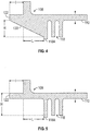
- the opening force is determined by the axial position of The tooth (referred to herein as "longest tooth 118A") that projects furthest radially away from the sealing surface 110 of the shoe 108. Two axial distances are referenced in FIGS. 2 , 4 and 5 .
- an axial region of the shoe 108 referenced with 1 represents the upstream (high) pressure acting on both the upper and lower surfaces of the seal in the limit of zero clearance.
- the lift force on the lower surface cancels with the force on the upper surface over the axial region 1 near 0 gap and this region thus does not contribute to the effective aerodynamic lift force that is a function of the axial length represented with character L, which extends from the axially rearward location of length 1 to the axial forward side of the longest tooth.
- the radial distance from the radial end of the longest tooth to the sealing surface 110 is referenced with H in FIGS. 2 , 4 and 5 .
- Dimensions L and H determine the aerodynamic lift force that provides the opening force during a "lock up" or "closed” condition with the tooth contacting the rotor 102.
- the longest tooth 118A is the most axial forward tooth.
- the embodiments disclosed herein provide a seal opening force that is equal or greater than two times the friction force to prevent seal lock-up. Therefore, the opening force assuredly overcomes the friction force, with margin.
- the axial distance L is greater than the radial distance H.
- FIGS. 2 and 4 illustrate a ramp 130 proximate the leading edge of the shoe 108.
- the ramp 130 may be oriented at different angles in various embodiments.
- FIG. 4 illustrates a steeper angle that leads to the longest tooth 118A over a shorter axial distance, when compared to the ramp of FIG. 2 .
- the specific dimensions will be dictated by the coefficient of friction, as described above in detail.
- the ramp 130 maintains the desired opening force behavior of the seal 100 for situations where the seal 100 has experienced tooth wear which may occur in operation during contact with the rotor, which without the ramp 130 may result in degradation of the maximum opening force that can be generated.
- FIG. 5 illustrates an embodiment of the shoe 108 that does not include an angled ramp 130. Regardless of the particular geometry at the leading edge of the shoe 108, the length L and height H must be optimized to provide the sufficient opening force that exceeds the frictional force.
- the embodiments described herein improve the opening force characteristics of the seal 100, such that the seal will always open (i.e., not get stuck by friction). This protects the seal 100 under maneuver conditions, which is particularly important for certain applications, such as military engines.
Landscapes
- Engineering & Computer Science (AREA)
- General Engineering & Computer Science (AREA)
- Mechanical Engineering (AREA)
- Turbine Rotor Nozzle Sealing (AREA)
Applications Claiming Priority (1)
| Application Number | Priority Date | Filing Date | Title |
|---|---|---|---|
| US16/239,611 US10961858B2 (en) | 2019-01-04 | 2019-01-04 | Hydrostatic seal with enhanced maneuver response |
Publications (2)
| Publication Number | Publication Date |
|---|---|
| EP3680520A1 true EP3680520A1 (de) | 2020-07-15 |
| EP3680520B1 EP3680520B1 (de) | 2025-03-19 |
Family
ID=69055919
Family Applications (1)
| Application Number | Title | Priority Date | Filing Date |
|---|---|---|---|
| EP19220241.4A Active EP3680520B1 (de) | 2019-01-04 | 2019-12-31 | Hydrostatische dichtung mit verbesserter manöverantwort |
Country Status (2)
| Country | Link |
|---|---|
| US (1) | US10961858B2 (de) |
| EP (1) | EP3680520B1 (de) |
Families Citing this family (7)
| Publication number | Priority date | Publication date | Assignee | Title |
|---|---|---|---|---|
| US11674402B2 (en) | 2018-11-28 | 2023-06-13 | Raytheon Technologies Corporation | Hydrostatic seal with non-parallel beams for anti-tipping |
| US11421543B2 (en) * | 2018-11-28 | 2022-08-23 | Raytheon Technologies Corporation | Hydrostatic seal with asymmetric beams for anti-tipping |
| US10995861B2 (en) | 2019-01-03 | 2021-05-04 | Raytheon Technologies Corporation | Cantilevered hydrostatic advanced low leakage seal |
| US10982770B2 (en) | 2019-01-03 | 2021-04-20 | Raytheon Technologies Corporation | Hydrostatic seal with extended housing |
| US11378187B2 (en) | 2019-01-03 | 2022-07-05 | Raytheon Technologies Corporation | Articulating cantilevered hydrostatic seal |
| US10975713B2 (en) | 2019-01-04 | 2021-04-13 | Raytheon Technologies Corporation | Hydrostatic seal with aft tooth |
| US12503950B2 (en) * | 2024-05-03 | 2025-12-23 | Rtx Corporation | Non-contact seal shoe with diffuser structure |
Citations (2)
| Publication number | Priority date | Publication date | Assignee | Title |
|---|---|---|---|---|
| US20130234399A1 (en) * | 2003-05-01 | 2013-09-12 | John F. Justak | Self-adjusting non-contact seal |
| EP3009612A1 (de) * | 2014-10-14 | 2016-04-20 | United Technologies Corporation | Berührungslose dichtung |
Family Cites Families (43)
| Publication number | Priority date | Publication date | Assignee | Title |
|---|---|---|---|---|
| US1187212A (en) * | 1913-08-20 | 1916-06-13 | Westinghouse Machine Co | Gland-packing. |
| GB1224234A (en) * | 1968-07-19 | 1971-03-03 | English Electric Co Ltd | Turbines |
| SE405406B (sv) * | 1972-12-05 | 1978-12-04 | Polysius Ag | Avtaetningsanordning foer en baerbaneaxel vid en vandringsrost |
| CH582319A5 (de) * | 1975-03-05 | 1976-11-30 | Bbc Brown Boveri & Cie | |
| DE2743825C2 (de) * | 1977-09-29 | 1986-01-30 | SKF GmbH, 8720 Schweinfurt | Rollenmeißel |
| US4428587A (en) * | 1983-05-10 | 1984-01-31 | Firma Carl Freudenberg | Seal ring with channel for radially accelerating medium to be sealed |
| DE3828833A1 (de) | 1988-08-25 | 1990-03-01 | Mtu Muenchen Gmbh | Einrichtung zur abdichtung von durch medien, wie fluessigkeiten und/oder gasen, unterschiedlichen druckes beaufschlagten raeumen, insbesondere fuer turbomaschinen |
| US5626347A (en) * | 1994-09-29 | 1997-05-06 | Alliedsignal Inc. | Coning resistant face seal having a "U" shape |
| FR2782122B1 (fr) | 1998-08-05 | 2000-09-15 | Snecma | Agencement d'etancheite a reglage automatique de jeu |
| US6250640B1 (en) | 1998-08-17 | 2001-06-26 | General Electric Co. | Brush seals for steam turbine applications |
| EP1169586B1 (de) | 2000-01-31 | 2007-02-21 | General Electric Company | Bürstendichtung zur verwendung in dampfturbine |
| US6715766B2 (en) * | 2001-10-30 | 2004-04-06 | General Electric Company | Steam feed hole for retractable packing segments in rotary machines |
| US6669443B2 (en) | 2001-11-16 | 2003-12-30 | General Electric Company | Rotor platform modification and methods using brush seals in diaphragm packing area of steam turbines to eliminate rotor bowing |
| US8002285B2 (en) * | 2003-05-01 | 2011-08-23 | Justak John F | Non-contact seal for a gas turbine engine |
| US8641045B2 (en) * | 2003-05-01 | 2014-02-04 | Advanced Technologies Group, Inc. | Seal with stacked sealing elements |
| US8172232B2 (en) | 2003-05-01 | 2012-05-08 | Advanced Technologies Group, Inc. | Non-contact seal for a gas turbine engine |
| US7410173B2 (en) * | 2003-05-01 | 2008-08-12 | Justak John F | Hydrodynamic brush seal |
| US7896352B2 (en) * | 2003-05-01 | 2011-03-01 | Justak John F | Seal with stacked sealing elements |
| US20050200080A1 (en) * | 2004-03-10 | 2005-09-15 | Siemens Westinghouse Power Corporation | Seal for a turbine engine |
| US7735833B2 (en) | 2006-11-14 | 2010-06-15 | The University Of Akron | Double padded finger seal |
| US8905408B2 (en) * | 2008-05-22 | 2014-12-09 | Stein Seal Company | Windback device for a circumferential seal |
| US8474827B2 (en) | 2010-06-11 | 2013-07-02 | Cmg Tech, Llc | Film riding pressure actuated leaf seal assembly |
| US8600707B1 (en) | 2011-03-24 | 2013-12-03 | Florida Turbine Technologies, Inc. | Process for analyzing a labyrinth seal for flutter |
| US9255642B2 (en) * | 2012-07-06 | 2016-02-09 | General Electric Company | Aerodynamic seals for rotary machine |
| US9587746B2 (en) | 2012-07-31 | 2017-03-07 | General Electric Company | Film riding seals for rotary machines |
| US9115810B2 (en) | 2012-10-31 | 2015-08-25 | General Electric Company | Pressure actuated film riding seals for turbo machinery |
| US9045994B2 (en) | 2012-10-31 | 2015-06-02 | General Electric Company | Film riding aerodynamic seals for rotary machines |
| US9587505B2 (en) * | 2013-12-05 | 2017-03-07 | General Electric Company | L brush seal for turbomachinery application |
| WO2015147967A1 (en) | 2014-03-27 | 2015-10-01 | United Technologies Corporation | Gas turbine engine and seal assembly therefore |
| US9359908B2 (en) * | 2014-07-08 | 2016-06-07 | General Electric Company | Film riding seal assembly for turbomachinery |
| US9963991B2 (en) * | 2014-10-01 | 2018-05-08 | United Technologies Corporation | Brush seal plate |
| US9988921B2 (en) | 2014-10-17 | 2018-06-05 | United Technologies Corporation | Circumferential seal with seal dampening elements |
| US20160109025A1 (en) | 2014-10-21 | 2016-04-21 | United Technologies Corporation | Seal ring |
| EP3034801B1 (de) | 2014-10-23 | 2025-10-15 | RTX Corporation | Dichtungsstützstruktur |
| US10094232B2 (en) | 2015-08-13 | 2018-10-09 | United Technologies Corporation | Self crystalline orientation for increased compliance |
| US10030531B2 (en) * | 2016-01-22 | 2018-07-24 | United Technologies Corporation | Seal shoe for a hydrostatic non-contact seal device |
| US10060535B2 (en) | 2016-02-25 | 2018-08-28 | United Technologies Corporation | Shaped spring element for a non-contact seal device |
| US20170306780A1 (en) * | 2016-04-25 | 2017-10-26 | United Technologies Corporation | Floating, non-contact seal with rounded edge |
| US10415413B2 (en) * | 2016-09-01 | 2019-09-17 | United Technologies Corporation | Floating non-contact seal vertical lip |
| US10982770B2 (en) | 2019-01-03 | 2021-04-20 | Raytheon Technologies Corporation | Hydrostatic seal with extended housing |
| US11378187B2 (en) | 2019-01-03 | 2022-07-05 | Raytheon Technologies Corporation | Articulating cantilevered hydrostatic seal |
| US10995861B2 (en) | 2019-01-03 | 2021-05-04 | Raytheon Technologies Corporation | Cantilevered hydrostatic advanced low leakage seal |
| US10975713B2 (en) | 2019-01-04 | 2021-04-13 | Raytheon Technologies Corporation | Hydrostatic seal with aft tooth |
-
2019
- 2019-01-04 US US16/239,611 patent/US10961858B2/en active Active
- 2019-12-31 EP EP19220241.4A patent/EP3680520B1/de active Active
Patent Citations (2)
| Publication number | Priority date | Publication date | Assignee | Title |
|---|---|---|---|---|
| US20130234399A1 (en) * | 2003-05-01 | 2013-09-12 | John F. Justak | Self-adjusting non-contact seal |
| EP3009612A1 (de) * | 2014-10-14 | 2016-04-20 | United Technologies Corporation | Berührungslose dichtung |
Also Published As
| Publication number | Publication date |
|---|---|
| EP3680520B1 (de) | 2025-03-19 |
| US20200217215A1 (en) | 2020-07-09 |
| US10961858B2 (en) | 2021-03-30 |
Similar Documents
| Publication | Publication Date | Title |
|---|---|---|
| EP3677818B1 (de) | Freitragende hydrostatische fortschrittliche dichtung mit geringer leckage | |
| EP3680520B1 (de) | Hydrostatische dichtung mit verbesserter manöverantwort | |
| EP3677817B1 (de) | Hydrostatische dichtung mit verlängertem gehäuse | |
| US11519285B2 (en) | Bellows secondary seal for cantilevered hydrostatic advanced low leakage seal | |
| US10066496B2 (en) | Gas turbine engine and seal assembly therefore | |
| EP3680521B1 (de) | Hydrostatische dichtung mit hinterem zahn | |
| EP3722560B1 (de) | Hydrostatische dichtung mit strukturellem schutz durch sekundärdichtung | |
| EP3789589B1 (de) | Hydrostatische dichtung | |
| EP3677816B1 (de) | Gelenkige freitragende hydrostatische dichtung | |
| EP3789588B1 (de) | Hydrostatische dichtung ausgerichtet mit der rotordrehrichtung | |
| EP3660274A1 (de) | Hydrostatische dichtung mit erhöhtem designraum | |
| EP3660362B1 (de) | Hydrostatische dichtung mit asymmetrischen stützen als kippschutz | |
| EP3739241B1 (de) | Sekundäre bürstendichtung für eine freitragende hydrostatische fortschrittliche dichtung mit geringer leckage | |
| EP3660363A1 (de) | Hydrostatische dichtung mit nichtparallelen trägern zum verhindern des kippens | |
| EP4560114A1 (de) | Kolbenringdichtung |
Legal Events
| Date | Code | Title | Description |
|---|---|---|---|
| PUAI | Public reference made under article 153(3) epc to a published international application that has entered the european phase |
Free format text: ORIGINAL CODE: 0009012 |
|
| STAA | Information on the status of an ep patent application or granted ep patent |
Free format text: STATUS: THE APPLICATION HAS BEEN PUBLISHED |
|
| AK | Designated contracting states |
Kind code of ref document: A1 Designated state(s): AL AT BE BG CH CY CZ DE DK EE ES FI FR GB GR HR HU IE IS IT LI LT LU LV MC MK MT NL NO PL PT RO RS SE SI SK SM TR |
|
| AX | Request for extension of the european patent |
Extension state: BA ME |
|
| STAA | Information on the status of an ep patent application or granted ep patent |
Free format text: STATUS: REQUEST FOR EXAMINATION WAS MADE |
|
| 17P | Request for examination filed |
Effective date: 20210112 |
|
| RBV | Designated contracting states (corrected) |
Designated state(s): AL AT BE BG CH CY CZ DE DK EE ES FI FR GB GR HR HU IE IS IT LI LT LU LV MC MK MT NL NO PL PT RO RS SE SI SK SM TR |
|
| RAP1 | Party data changed (applicant data changed or rights of an application transferred) |
Owner name: RAYTHEON TECHNOLOGIES CORPORATION |
|
| STAA | Information on the status of an ep patent application or granted ep patent |
Free format text: STATUS: EXAMINATION IS IN PROGRESS |
|
| 17Q | First examination report despatched |
Effective date: 20210503 |
|
| REG | Reference to a national code |
Ref country code: DE Ipc: F01D0011020000 Ref legal event code: R079 Ref document number: 602019067436 Country of ref document: DE Free format text: PREVIOUS MAIN CLASS: F16J0015440000 |
|
| RIC1 | Information provided on ipc code assigned before grant |
Ipc: F16J 15/44 20060101ALI20230512BHEP Ipc: F01D 11/02 20060101AFI20230512BHEP |
|
| RAP3 | Party data changed (applicant data changed or rights of an application transferred) |
Owner name: RTX CORPORATION |
|
| GRAP | Despatch of communication of intention to grant a patent |
Free format text: ORIGINAL CODE: EPIDOSNIGR1 |
|
| STAA | Information on the status of an ep patent application or granted ep patent |
Free format text: STATUS: GRANT OF PATENT IS INTENDED |
|
| INTG | Intention to grant announced |
Effective date: 20240508 |
|
| GRAJ | Information related to disapproval of communication of intention to grant by the applicant or resumption of examination proceedings by the epo deleted |
Free format text: ORIGINAL CODE: EPIDOSDIGR1 |
|
| STAA | Information on the status of an ep patent application or granted ep patent |
Free format text: STATUS: EXAMINATION IS IN PROGRESS |
|
| GRAP | Despatch of communication of intention to grant a patent |
Free format text: ORIGINAL CODE: EPIDOSNIGR1 |
|
| STAA | Information on the status of an ep patent application or granted ep patent |
Free format text: STATUS: GRANT OF PATENT IS INTENDED |
|
| INTC | Intention to grant announced (deleted) | ||
| INTG | Intention to grant announced |
Effective date: 20241010 |
|
| GRAS | Grant fee paid |
Free format text: ORIGINAL CODE: EPIDOSNIGR3 |
|
| GRAA | (expected) grant |
Free format text: ORIGINAL CODE: 0009210 |
|
| STAA | Information on the status of an ep patent application or granted ep patent |
Free format text: STATUS: THE PATENT HAS BEEN GRANTED |
|
| AK | Designated contracting states |
Kind code of ref document: B1 Designated state(s): AL AT BE BG CH CY CZ DE DK EE ES FI FR GB GR HR HU IE IS IT LI LT LU LV MC MK MT NL NO PL PT RO RS SE SI SK SM TR |
|
| REG | Reference to a national code |
Ref country code: GB Ref legal event code: FG4D |
|
| REG | Reference to a national code |
Ref country code: CH Ref legal event code: EP |
|
| REG | Reference to a national code |
Ref country code: DE Ref legal event code: R096 Ref document number: 602019067436 Country of ref document: DE |
|
| REG | Reference to a national code |
Ref country code: IE Ref legal event code: FG4D |
|
| PG25 | Lapsed in a contracting state [announced via postgrant information from national office to epo] |
Ref country code: RS Free format text: LAPSE BECAUSE OF FAILURE TO SUBMIT A TRANSLATION OF THE DESCRIPTION OR TO PAY THE FEE WITHIN THE PRESCRIBED TIME-LIMIT Effective date: 20250619 |
|
| PG25 | Lapsed in a contracting state [announced via postgrant information from national office to epo] |
Ref country code: FI Free format text: LAPSE BECAUSE OF FAILURE TO SUBMIT A TRANSLATION OF THE DESCRIPTION OR TO PAY THE FEE WITHIN THE PRESCRIBED TIME-LIMIT Effective date: 20250319 |
|
| REG | Reference to a national code |
Ref country code: LT Ref legal event code: MG9D |
|
| PG25 | Lapsed in a contracting state [announced via postgrant information from national office to epo] |
Ref country code: NO Free format text: LAPSE BECAUSE OF FAILURE TO SUBMIT A TRANSLATION OF THE DESCRIPTION OR TO PAY THE FEE WITHIN THE PRESCRIBED TIME-LIMIT Effective date: 20250619 |
|
| PG25 | Lapsed in a contracting state [announced via postgrant information from national office to epo] |
Ref country code: HR Free format text: LAPSE BECAUSE OF FAILURE TO SUBMIT A TRANSLATION OF THE DESCRIPTION OR TO PAY THE FEE WITHIN THE PRESCRIBED TIME-LIMIT Effective date: 20250319 |
|
| PG25 | Lapsed in a contracting state [announced via postgrant information from national office to epo] |
Ref country code: LV Free format text: LAPSE BECAUSE OF FAILURE TO SUBMIT A TRANSLATION OF THE DESCRIPTION OR TO PAY THE FEE WITHIN THE PRESCRIBED TIME-LIMIT Effective date: 20250319 |
|
| PG25 | Lapsed in a contracting state [announced via postgrant information from national office to epo] |
Ref country code: GR Free format text: LAPSE BECAUSE OF FAILURE TO SUBMIT A TRANSLATION OF THE DESCRIPTION OR TO PAY THE FEE WITHIN THE PRESCRIBED TIME-LIMIT Effective date: 20250620 Ref country code: BG Free format text: LAPSE BECAUSE OF FAILURE TO SUBMIT A TRANSLATION OF THE DESCRIPTION OR TO PAY THE FEE WITHIN THE PRESCRIBED TIME-LIMIT Effective date: 20250319 |
|
| REG | Reference to a national code |
Ref country code: NL Ref legal event code: MP Effective date: 20250319 |
|
| REG | Reference to a national code |
Ref country code: AT Ref legal event code: MK05 Ref document number: 1777095 Country of ref document: AT Kind code of ref document: T Effective date: 20250319 |
|
| PG25 | Lapsed in a contracting state [announced via postgrant information from national office to epo] |
Ref country code: NL Free format text: LAPSE BECAUSE OF FAILURE TO SUBMIT A TRANSLATION OF THE DESCRIPTION OR TO PAY THE FEE WITHIN THE PRESCRIBED TIME-LIMIT Effective date: 20250319 |
|
| PG25 | Lapsed in a contracting state [announced via postgrant information from national office to epo] |
Ref country code: SE Free format text: LAPSE BECAUSE OF FAILURE TO SUBMIT A TRANSLATION OF THE DESCRIPTION OR TO PAY THE FEE WITHIN THE PRESCRIBED TIME-LIMIT Effective date: 20250319 |
|
| PG25 | Lapsed in a contracting state [announced via postgrant information from national office to epo] |
Ref country code: SM Free format text: LAPSE BECAUSE OF FAILURE TO SUBMIT A TRANSLATION OF THE DESCRIPTION OR TO PAY THE FEE WITHIN THE PRESCRIBED TIME-LIMIT Effective date: 20250319 |
|
| PG25 | Lapsed in a contracting state [announced via postgrant information from national office to epo] |
Ref country code: ES Free format text: LAPSE BECAUSE OF FAILURE TO SUBMIT A TRANSLATION OF THE DESCRIPTION OR TO PAY THE FEE WITHIN THE PRESCRIBED TIME-LIMIT Effective date: 20250319 Ref country code: PT Free format text: LAPSE BECAUSE OF FAILURE TO SUBMIT A TRANSLATION OF THE DESCRIPTION OR TO PAY THE FEE WITHIN THE PRESCRIBED TIME-LIMIT Effective date: 20250721 |
|
| PG25 | Lapsed in a contracting state [announced via postgrant information from national office to epo] |
Ref country code: IT Free format text: LAPSE BECAUSE OF FAILURE TO SUBMIT A TRANSLATION OF THE DESCRIPTION OR TO PAY THE FEE WITHIN THE PRESCRIBED TIME-LIMIT Effective date: 20250319 Ref country code: PL Free format text: LAPSE BECAUSE OF FAILURE TO SUBMIT A TRANSLATION OF THE DESCRIPTION OR TO PAY THE FEE WITHIN THE PRESCRIBED TIME-LIMIT Effective date: 20250319 |
|
| PG25 | Lapsed in a contracting state [announced via postgrant information from national office to epo] |
Ref country code: AT Free format text: LAPSE BECAUSE OF FAILURE TO SUBMIT A TRANSLATION OF THE DESCRIPTION OR TO PAY THE FEE WITHIN THE PRESCRIBED TIME-LIMIT Effective date: 20250319 |
|
| PG25 | Lapsed in a contracting state [announced via postgrant information from national office to epo] |
Ref country code: CZ Free format text: LAPSE BECAUSE OF FAILURE TO SUBMIT A TRANSLATION OF THE DESCRIPTION OR TO PAY THE FEE WITHIN THE PRESCRIBED TIME-LIMIT Effective date: 20250319 Ref country code: EE Free format text: LAPSE BECAUSE OF FAILURE TO SUBMIT A TRANSLATION OF THE DESCRIPTION OR TO PAY THE FEE WITHIN THE PRESCRIBED TIME-LIMIT Effective date: 20250319 |
|
| PG25 | Lapsed in a contracting state [announced via postgrant information from national office to epo] |
Ref country code: RO Free format text: LAPSE BECAUSE OF FAILURE TO SUBMIT A TRANSLATION OF THE DESCRIPTION OR TO PAY THE FEE WITHIN THE PRESCRIBED TIME-LIMIT Effective date: 20250319 |
|
| PG25 | Lapsed in a contracting state [announced via postgrant information from national office to epo] |
Ref country code: SK Free format text: LAPSE BECAUSE OF FAILURE TO SUBMIT A TRANSLATION OF THE DESCRIPTION OR TO PAY THE FEE WITHIN THE PRESCRIBED TIME-LIMIT Effective date: 20250319 |
|
| PG25 | Lapsed in a contracting state [announced via postgrant information from national office to epo] |
Ref country code: IS Free format text: LAPSE BECAUSE OF FAILURE TO SUBMIT A TRANSLATION OF THE DESCRIPTION OR TO PAY THE FEE WITHIN THE PRESCRIBED TIME-LIMIT Effective date: 20250719 |
|
| REG | Reference to a national code |
Ref country code: DE Ref legal event code: R097 Ref document number: 602019067436 Country of ref document: DE |
|
| PGFP | Annual fee paid to national office [announced via postgrant information from national office to epo] |
Ref country code: DE Payment date: 20251126 Year of fee payment: 7 |
|
| PGFP | Annual fee paid to national office [announced via postgrant information from national office to epo] |
Ref country code: GB Payment date: 20251120 Year of fee payment: 7 |
|
| PG25 | Lapsed in a contracting state [announced via postgrant information from national office to epo] |
Ref country code: DK Free format text: LAPSE BECAUSE OF FAILURE TO SUBMIT A TRANSLATION OF THE DESCRIPTION OR TO PAY THE FEE WITHIN THE PRESCRIBED TIME-LIMIT Effective date: 20250319 |
|
| PGFP | Annual fee paid to national office [announced via postgrant information from national office to epo] |
Ref country code: FR Payment date: 20251120 Year of fee payment: 7 |
|
| PLBE | No opposition filed within time limit |
Free format text: ORIGINAL CODE: 0009261 |
|
| STAA | Information on the status of an ep patent application or granted ep patent |
Free format text: STATUS: NO OPPOSITION FILED WITHIN TIME LIMIT |
|
| REG | Reference to a national code |
Ref country code: CH Ref legal event code: L10 Free format text: ST27 STATUS EVENT CODE: U-0-0-L10-L00 (AS PROVIDED BY THE NATIONAL OFFICE) Effective date: 20260128 |
|
| 26N | No opposition filed |
Effective date: 20251222 |