EP3680533B1 - Élément de section profilée avec paroi latérale à gradins - Google Patents
Élément de section profilée avec paroi latérale à gradins Download PDFInfo
- Publication number
- EP3680533B1 EP3680533B1 EP19217945.5A EP19217945A EP3680533B1 EP 3680533 B1 EP3680533 B1 EP 3680533B1 EP 19217945 A EP19217945 A EP 19217945A EP 3680533 B1 EP3680533 B1 EP 3680533B1
- Authority
- EP
- European Patent Office
- Prior art keywords
- profiled section
- holes
- section element
- row
- top side
- Prior art date
- Legal status (The legal status is an assumption and is not a legal conclusion. Google has not performed a legal analysis and makes no representation as to the accuracy of the status listed.)
- Active
Links
Images



Classifications
-
- F—MECHANICAL ENGINEERING; LIGHTING; HEATING; WEAPONS; BLASTING
- F16—ENGINEERING ELEMENTS AND UNITS; GENERAL MEASURES FOR PRODUCING AND MAINTAINING EFFECTIVE FUNCTIONING OF MACHINES OR INSTALLATIONS; THERMAL INSULATION IN GENERAL
- F16L—PIPES; JOINTS OR FITTINGS FOR PIPES; SUPPORTS FOR PIPES, CABLES OR PROTECTIVE TUBING; MEANS FOR THERMAL INSULATION IN GENERAL
- F16L3/00—Supports for pipes, cables or protective tubing, e.g. hangers, holders, clamps, cleats, clips, brackets
- F16L3/003—Supports for pipes, cables or protective tubing, e.g. hangers, holders, clamps, cleats, clips, brackets devices for holding the open end of a hose
-
- E—FIXED CONSTRUCTIONS
- E04—BUILDING
- E04B—GENERAL BUILDING CONSTRUCTIONS; WALLS, e.g. PARTITIONS; ROOFS; FLOORS; CEILINGS; INSULATION OR OTHER PROTECTION OF BUILDINGS
- E04B2/00—Walls, e.g. partitions, for buildings; Wall construction with regard to insulation; Connections specially adapted to walls
- E04B2/74—Removable non-load-bearing partitions; Partitions with a free upper edge
- E04B2/7407—Removable non-load-bearing partitions; Partitions with a free upper edge assembled using frames with infill panels or coverings only; made-up of panels and a support structure incorporating posts
- E04B2/7453—Removable non-load-bearing partitions; Partitions with a free upper edge assembled using frames with infill panels or coverings only; made-up of panels and a support structure incorporating posts with panels and support posts, extending from floor to ceiling
- E04B2/7457—Removable non-load-bearing partitions; Partitions with a free upper edge assembled using frames with infill panels or coverings only; made-up of panels and a support structure incorporating posts with panels and support posts, extending from floor to ceiling with wallboards attached to the outer faces of the posts, parallel to the partition
-
- B—PERFORMING OPERATIONS; TRANSPORTING
- B05—SPRAYING OR ATOMISING IN GENERAL; APPLYING FLUENT MATERIALS TO SURFACES, IN GENERAL
- B05B—SPRAYING APPARATUS; ATOMISING APPARATUS; NOZZLES
- B05B15/00—Details of spraying plant or spraying apparatus not otherwise provided for; Accessories
- B05B15/60—Arrangements for mounting, supporting or holding spraying apparatus
- B05B15/62—Arrangements for supporting spraying apparatus, e.g. suction cups
-
- B—PERFORMING OPERATIONS; TRANSPORTING
- B05—SPRAYING OR ATOMISING IN GENERAL; APPLYING FLUENT MATERIALS TO SURFACES, IN GENERAL
- B05B—SPRAYING APPARATUS; ATOMISING APPARATUS; NOZZLES
- B05B15/00—Details of spraying plant or spraying apparatus not otherwise provided for; Accessories
- B05B15/60—Arrangements for mounting, supporting or holding spraying apparatus
- B05B15/68—Arrangements for adjusting the position of spray heads
-
- E—FIXED CONSTRUCTIONS
- E03—WATER SUPPLY; SEWERAGE
- E03C—DOMESTIC PLUMBING INSTALLATIONS FOR FRESH WATER OR WASTE WATER; SINKS
- E03C1/00—Domestic plumbing installations for fresh water or waste water; Sinks
- E03C1/02—Plumbing installations for fresh water
- E03C1/021—Devices for positioning or connecting of water supply lines
-
- E—FIXED CONSTRUCTIONS
- E03—WATER SUPPLY; SEWERAGE
- E03C—DOMESTIC PLUMBING INSTALLATIONS FOR FRESH WATER OR WASTE WATER; SINKS
- E03C1/00—Domestic plumbing installations for fresh water or waste water; Sinks
- E03C1/02—Plumbing installations for fresh water
- E03C1/06—Devices for suspending or supporting the supply pipe or supply hose of a shower-bath
-
- E—FIXED CONSTRUCTIONS
- E04—BUILDING
- E04C—STRUCTURAL ELEMENTS; BUILDING MATERIALS
- E04C3/00—Structural elongated elements designed for load-supporting
- E04C3/005—Girders or columns that are rollable, collapsible or otherwise adjustable in length or height
-
- F—MECHANICAL ENGINEERING; LIGHTING; HEATING; WEAPONS; BLASTING
- F16—ENGINEERING ELEMENTS AND UNITS; GENERAL MEASURES FOR PRODUCING AND MAINTAINING EFFECTIVE FUNCTIONING OF MACHINES OR INSTALLATIONS; THERMAL INSULATION IN GENERAL
- F16L—PIPES; JOINTS OR FITTINGS FOR PIPES; SUPPORTS FOR PIPES, CABLES OR PROTECTIVE TUBING; MEANS FOR THERMAL INSULATION IN GENERAL
- F16L3/00—Supports for pipes, cables or protective tubing, e.g. hangers, holders, clamps, cleats, clips, brackets
- F16L3/24—Supports for pipes, cables or protective tubing, e.g. hangers, holders, clamps, cleats, clips, brackets with special member for attachment to profiled girders
-
- F—MECHANICAL ENGINEERING; LIGHTING; HEATING; WEAPONS; BLASTING
- F16—ENGINEERING ELEMENTS AND UNITS; GENERAL MEASURES FOR PRODUCING AND MAINTAINING EFFECTIVE FUNCTIONING OF MACHINES OR INSTALLATIONS; THERMAL INSULATION IN GENERAL
- F16L—PIPES; JOINTS OR FITTINGS FOR PIPES; SUPPORTS FOR PIPES, CABLES OR PROTECTIVE TUBING; MEANS FOR THERMAL INSULATION IN GENERAL
- F16L5/00—Devices for use where pipes, cables or protective tubing pass through walls or partitions
-
- H—ELECTRICITY
- H02—GENERATION; CONVERSION OR DISTRIBUTION OF ELECTRIC POWER
- H02G—INSTALLATION OF ELECTRIC CABLES OR LINES, OR OF COMBINED OPTICAL AND ELECTRIC CABLES OR LINES
- H02G3/00—Installations of electric cables or lines or protective tubing therefor in or on buildings, equivalent structures or vehicles
- H02G3/02—Details
- H02G3/08—Distribution boxes; Connection or junction boxes
- H02G3/12—Distribution boxes; Connection or junction boxes for flush mounting
- H02G3/123—Distribution boxes; Connection or junction boxes for flush mounting in thin walls
- H02G3/125—Distribution boxes; Connection or junction boxes for flush mounting in thin walls with supporting bar extending between two separate studs of a wall frame
-
- E—FIXED CONSTRUCTIONS
- E04—BUILDING
- E04B—GENERAL BUILDING CONSTRUCTIONS; WALLS, e.g. PARTITIONS; ROOFS; FLOORS; CEILINGS; INSULATION OR OTHER PROTECTION OF BUILDINGS
- E04B2/00—Walls, e.g. partitions, for buildings; Wall construction with regard to insulation; Connections specially adapted to walls
- E04B2/74—Removable non-load-bearing partitions; Partitions with a free upper edge
- E04B2002/7483—Details of furniture, e.g. tables or shelves, associated with the partitions
- E04B2002/7485—Load supports therefor placed between wall studs
-
- E—FIXED CONSTRUCTIONS
- E04—BUILDING
- E04B—GENERAL BUILDING CONSTRUCTIONS; WALLS, e.g. PARTITIONS; ROOFS; FLOORS; CEILINGS; INSULATION OR OTHER PROTECTION OF BUILDINGS
- E04B2/00—Walls, e.g. partitions, for buildings; Wall construction with regard to insulation; Connections specially adapted to walls
- E04B2/74—Removable non-load-bearing partitions; Partitions with a free upper edge
- E04B2002/7488—Details of wiring
-
- E—FIXED CONSTRUCTIONS
- E04—BUILDING
- E04C—STRUCTURAL ELEMENTS; BUILDING MATERIALS
- E04C3/00—Structural elongated elements designed for load-supporting
- E04C3/02—Joists; Girders, trusses, or trusslike structures, e.g. prefabricated; Lintels; Transoms; Braces
- E04C2003/026—Braces
-
- E—FIXED CONSTRUCTIONS
- E04—BUILDING
- E04C—STRUCTURAL ELEMENTS; BUILDING MATERIALS
- E04C3/00—Structural elongated elements designed for load-supporting
- E04C3/02—Joists; Girders, trusses, or trusslike structures, e.g. prefabricated; Lintels; Transoms; Braces
- E04C3/04—Joists; Girders, trusses, or trusslike structures, e.g. prefabricated; Lintels; Transoms; Braces of metal
- E04C2003/0404—Joists; Girders, trusses, or trusslike structures, e.g. prefabricated; Lintels; Transoms; Braces of metal beams, girders, or joists characterised by cross-sectional aspects
- E04C2003/0443—Joists; Girders, trusses, or trusslike structures, e.g. prefabricated; Lintels; Transoms; Braces of metal beams, girders, or joists characterised by cross-sectional aspects characterised by substantial shape of the cross-section
- E04C2003/0473—U- or C-shaped
-
- F—MECHANICAL ENGINEERING; LIGHTING; HEATING; WEAPONS; BLASTING
- F16—ENGINEERING ELEMENTS AND UNITS; GENERAL MEASURES FOR PRODUCING AND MAINTAINING EFFECTIVE FUNCTIONING OF MACHINES OR INSTALLATIONS; THERMAL INSULATION IN GENERAL
- F16B—DEVICES FOR FASTENING OR SECURING CONSTRUCTIONAL ELEMENTS OR MACHINE PARTS TOGETHER, e.g. NAILS, BOLTS, CIRCLIPS, CLAMPS, CLIPS OR WEDGES; JOINTS OR JOINTING
- F16B7/00—Connections of rods or tubes, e.g. of non-circular section, mutually, including resilient connections
- F16B7/10—Telescoping systems
- F16B7/105—Telescoping systems locking in discrete positions, e.g. in extreme extended position
-
- F—MECHANICAL ENGINEERING; LIGHTING; HEATING; WEAPONS; BLASTING
- F16—ENGINEERING ELEMENTS AND UNITS; GENERAL MEASURES FOR PRODUCING AND MAINTAINING EFFECTIVE FUNCTIONING OF MACHINES OR INSTALLATIONS; THERMAL INSULATION IN GENERAL
- F16B—DEVICES FOR FASTENING OR SECURING CONSTRUCTIONAL ELEMENTS OR MACHINE PARTS TOGETHER, e.g. NAILS, BOLTS, CIRCLIPS, CLAMPS, CLIPS OR WEDGES; JOINTS OR JOINTING
- F16B7/00—Connections of rods or tubes, e.g. of non-circular section, mutually, including resilient connections
- F16B7/18—Connections of rods or tubes, e.g. of non-circular section, mutually, including resilient connections using screw-thread elements
- F16B7/182—Connections of rods or tubes, e.g. of non-circular section, mutually, including resilient connections using screw-thread elements for coaxial connections of two rods or tubes
Definitions
- the invention relates to an elongate profiled section element for a mounting system, said profiled section element comprising a bottom, a top side opposite the bottom, and sidewalls extending from the bottom to the top side, wherein the top side comprises two flanges which extend from the side walls and delimit between them a longitudinal slot.
- At least interior walls are constructed as drywall including a stud construction.
- a stud construction includes a frame that is constituted by a floor framing member, a top framing member, and studs which are arranged in a parallel and spaced apart fashion and are attached to the top framing member and the bottom framing member.
- the stud frame is made of wood.
- the frame is covered with gypsum boards which are screwed to the studs.
- the gypsum boards may be finished with plaster.
- Each profile of the pair of profiles has a mounting plate connected to one end of the bottom of the profiled section element, by which the profiled section element can be mounted to a stud in the drywall.
- Document US 2018/062365 discloses an elongate profiled section element for a mounting system comprising all the features of the preamble of claim 1.
- the invention relates to an elongate profiled section element for a mounting system.
- the profiled section element comprises a bottom, a top side opposite the bottom, and sidewalls extending from the bottom to the top side.
- the top side comprises two flanges which extend from the side walls and delimit between them a longitudinal slot.
- the top side has a smaller width than the bottom.
- At least one of the sidewalls is a stepped sidewall having a stepped shape seen in cross section, said stepped sidewall having two wall sections facing the opposite sidewall and an intermediate wall section substantially parallel to the bottom.
- the intermediate wall section is provided with a row of holes and the bottom is provided with a row of holes aligned therewith, said holes being adapted to cooperate with a self tapping screw.
- the bottom is provided with a further row of holes which row faces the longitudinal slot.
- the bottom is provided with a further row of holes which row faces the flange extending from the sidewall opposite the stepped sidewall.
- a mounting plate provided with mounting holes is integrally formed on an end of the bottom.
- the invention also relates to an assembly of two profiled section elements according to the invention, wherein one of the profiled section elements fits telescopically in the other one.
- the invention furthermore relates to a stud wall structure wherein an assembly as mentioned above is mounted between two studs of the stud wall structure.
- a pipe fitting having mounting ears may be mounted to the bottom of the profiled section element by self tapping screws.
- a shower head may be fixed to the mentioned pipe fitting.
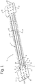
- Figs. 1 and 2 show a pair of telescopically arranged elongate profiled section elements 1 in perspective.
- Fig. 1 shows the pair of profiled section elements 1 in a more slided-in state and
- Fig. 2 shows the pair in a more extended state.
- Fig. 3 shows the cross-section of the pair in a location where they overlap.
- the profiled section elements 1 are substantially the same, but one has a slightly smaller dimensions to fit slidingly in the other one to allow a telescoping assembly of the two profiles.
- the profiled section element 1 comprises a bottom 2 and a top side 3 opposite the bottom 2.
- the top side 3 has a smaller width than the bottom 2.
- the top side includes two longitudinal flanges 6 and a longitudinal slot 20 between the flanges 6. This slot 20 may be used to fasten fastening units, such as well-known slidenut assemblies to the profiled section element as will be illustrated further below.
- the profiled section element furthermore includes sidewalls 4 and 5 extending from the bottom 2 to the top side 3.
- the side wall 4 is straight and extends substantially perpendicular to the bottom 2 and the top side 3.
- the other side wall 5 has a stepped shape.
- the stepped sidewall 5 has two wall sections 8, 9 which are upstanding with respect to the bottom 2 of the profiled section element 1. In a preferred embodiment the two side wall sections 8 and 9 extend substantially parallel to the opposite sidewall 4.
- the stepped sidewall 5 furthermore includes an intermediate wall section 7 parallel to the bottom 2 interconnecting the upstanding wall sections 8 and 9.
- Each profiled section element 1 comprises a mounting plate 14 on one end of the bottom 2.
- the mounting plate 14 is provided with a pattern of mounting holes 15.
- This mounting plate 14 is used to attach the respective profiled section elements 1 to, for example, the stud of a stud frame of a drywall. For this purpose, it may first be bent into another position at the joining line between the bottom 2 of the profiled section element 1 and the mounting plate 14, for example at a right angle relative to the bottom 2, but it can also be used in an in-line state in which plate is in line or flush with the bottom 2 of the profiled section element 1, as is shown in Figs. 1 and 2 .
- the two telescoping profiled section elements 1 can be moved with respect to each other, to adapt the length of the pair to fit between studs arranged at varying distances.
- Rows of holes 10, 11, 12, 13 are formed in both profiled section elements 1 of the pair.
- the holes 10, 11, 12, 13 may be adapted to cooperate with a self-tapping screw. That is the holes are small and allow a screw tip to be inserted to initiate the screwing in of the screw. The hole will be cut and enlarged by the screw which is advanced.
- the bottom has three rows of holes.
- the row of holes 11 faces the intermediate wall section 7 of the stepped sidewall 5.
- the row of holes 13 faces the flange 6 attached to the non-stepped sidewall 4 .
- the row of holes 12 faces the longitudinal slot 20 between the flanges 6.
- the intermediate wall section 7 of the stepped sidewall is provided with a row of holes 10, wherein the holes 10 are aligned with the holes 11 in the bottom 2.
- the invention also relates to elongated profiled section 1 which have less or more rows of holes, for example elongated profiled section 1 with only a row of holes 10 in the intermediate wall section 7 of the stepped sidewall 5 and a row of holes 11 aligned therewith in the bottom 2.
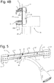
- Fig. 4 shows an example of how a plumbing component, in this case an elbow pipe fitting 16, may be attached to the elongate profiled section element 1.
- the pipe fitting 16 has three mounting ears 22 having a mounting hole for passing through fastening screws 21A, 21B.
- Three self-tapping screws 21A, 21B are used to fix the mounting ears 22 to the bottom 2 of the profiled section element 1, as is illustrated in Figs. 4(a) and 4(b) .
- the drop ear elbow fitting 16 shown in Figs 4 and 5 is only intended to be a non-limiting example of how a component may be attached to the profiled section elements 1.
- the screw 21A is entered through two aligned holes 11, 10 in the bottom 2 and the intermediate wall section 7 of the stepped sidewall 5.
- the other two screws 21B are entered through holes 13 in the bottom 2 which face the flange on the side of the not-stepped sidewall 4. If the elbow16 is attached on a location where the telescopically arranged profiled section elements 1 overlap, the first screw 21A passes through four layers of profiled section element material, which is preferably metal.
- the other two screws 21B cut and extend through two layers of profiled section element material, that is these screws extend through two overlapping bottoms 2. As can be best seen in Figs. 4(a) and 4(b) . If the fitting 16 is attached to a non-overlapping portion of one of the profiled section elements 1, the first screw 21A cuts and passes through to two layers, and the other screws 21B through one layer.
- the insertion of the screws through more layers makes the construction more rigid against vibrations, because there is more pressure on the screws when they are inserted and thereby more resistance to coming undone.
- the shape of the profiled section element 1 also allows products designed to be mounted on a classic, C-shaped profile section element to be mounted on the invention.
- the top side 3, comprising the longitudinal flanges 6 defining the longitudinal slot 20 between them, the non-stepped sidewall 4 and the upper wall section 9 of the stepped sidewall 5 constitute the shape, and preferably have the dimensions of an upper portion of a common C-shaped profiled section element.
- standard fastening components such as slidenut fasteners can be used on the top side of the profiled section element 1, also in the overlapping regions of two telescopically arranged profiled section elements 1 as is illustrated in Fig 6(a).
- Fig. 6(b) shows another example of a component that is designed to be mounted on a C-shaped mounting rail, can be mounted to the profiled section element 1 of the invention.
Landscapes
- Engineering & Computer Science (AREA)
- General Engineering & Computer Science (AREA)
- Architecture (AREA)
- Mechanical Engineering (AREA)
- Civil Engineering (AREA)
- Structural Engineering (AREA)
- Life Sciences & Earth Sciences (AREA)
- Health & Medical Sciences (AREA)
- Hydrology & Water Resources (AREA)
- Public Health (AREA)
- Water Supply & Treatment (AREA)
- Electromagnetism (AREA)
- Physics & Mathematics (AREA)
- Connection Of Plates (AREA)
- Domestic Plumbing Installations (AREA)
Claims (8)
- Elément de section profilée (1) allongé pour un système de montage, ledit élément de section profilée (1) comprenant un fond (2), un côté supérieur (3) opposé au fond (2), et des parois latérales (4, 5) s'étendant du fond (2) au côté supérieur (3), dans lequel le côté supérieur (3) comprend deux brides (6) qui s'étendent à partir des parois latérales (4, 5) et délimitent entre elles une fente longitudinale (20),caractérisé en ce que le côté supérieure (3) a une largeur inférieure à celle du fond (2),et en ce qu'au moins une des parois latérales (4, 5) est une paroi latérale étagée (5) ayant une forme étagée vue en section transversale, ladite paroi latérale étagée (5) ayant deux sections de paroi (8, 9) faisant face à la paroi latérale (4) opposée et une section de paroi intermédiaire (7) sensiblement parallèle au fond (2), eten ce que la section de paroi intermédiaire (7) est pourvue d'une rangée de trous (10) et le fond (2) est pourvu d'une rangée de trous (11) alignés avec celle-ci, lesdits trous (10, 11) étant adaptés pour coopérer avec une vis auto-taraudeuse.
- Elément de section profilée selon la revendication 1, dans lequel le fond (2) est pourvu d'une autre rangée de trous (12), laquelle rangée fait face à la fente longitudinale (20) .
- Elément de section profilée selon la revendication 1, dans lequel le fond (2) est pourvu d'une autre rangée de trous (13), laquelle rangée fait face à la bride (6) s'étendant depuis la paroi latérale (4) opposée à la paroi latérale étagée (5).
- Elément de section profilée selon la revendication 1, dans lequel une plaque de montage (14) munie de trous de montage (15) est formée d'un seul tenant sur une extrémité du fond (2) .
- Assemblage de deux éléments de section profilée (1) selon la revendication 1, dans lequel l'un des éléments de section profilée (1) s'emboîte de manière télescopique dans l'autre.
- Structure de mur à montants dans laquelle un assemblage selon la revendication 5 est monté entre deux montants de la structure de mur à montants.
- Structure de mur à montants selon la revendication 6, dans laquelle un raccord de tuyau (16) ayant des oreilles de montage (22) est monté sur le fond (2) de l'élément de section profilée (1) par des vis auto-taraudeuses.
- Structure de mur à montants selon la revendication 7, dans laquelle une pomme de douche (17) est fixée au raccord de tuyau (16).
Priority Applications (1)
| Application Number | Priority Date | Filing Date | Title |
|---|---|---|---|
| PL19217945T PL3680533T3 (pl) | 2019-01-14 | 2019-12-19 | Sekcyjny element profilowy ze ścianą schodkową |
Applications Claiming Priority (1)
| Application Number | Priority Date | Filing Date | Title |
|---|---|---|---|
| NL2022397A NL2022397B1 (en) | 2019-01-14 | 2019-01-14 | Profiled section element with stepped sidewall |
Publications (2)
| Publication Number | Publication Date |
|---|---|
| EP3680533A1 EP3680533A1 (fr) | 2020-07-15 |
| EP3680533B1 true EP3680533B1 (fr) | 2021-12-15 |
Family
ID=66049644
Family Applications (1)
| Application Number | Title | Priority Date | Filing Date |
|---|---|---|---|
| EP19217945.5A Active EP3680533B1 (fr) | 2019-01-14 | 2019-12-19 | Élément de section profilée avec paroi latérale à gradins |
Country Status (5)
| Country | Link |
|---|---|
| US (1) | US11047510B2 (fr) |
| EP (1) | EP3680533B1 (fr) |
| ES (1) | ES2904400T3 (fr) |
| NL (1) | NL2022397B1 (fr) |
| PL (1) | PL3680533T3 (fr) |
Families Citing this family (6)
| Publication number | Priority date | Publication date | Assignee | Title |
|---|---|---|---|---|
| EP3747312A1 (fr) * | 2019-06-05 | 2020-12-09 | Rol Ergo AB | Barre de support d'une table |
| CN118712978A (zh) * | 2019-07-31 | 2024-09-27 | 豪倍公司 | 电线支撑支架 |
| CN112942677B (zh) * | 2021-01-26 | 2022-04-12 | 上海绿地建设(集团)有限公司 | 一种装配式双侧板全螺栓钢连梁 |
| US12535168B2 (en) * | 2023-01-05 | 2026-01-27 | Richard Charles Guel | Systems and methods for supporting pipe |
| US12519294B1 (en) | 2023-03-16 | 2026-01-06 | Titan3 Technology LLC | Cable clamp for electrical junction box |
| US12573828B2 (en) | 2023-09-01 | 2026-03-10 | Erico International Corporation | Wire stub out clip |
Citations (1)
| Publication number | Priority date | Publication date | Assignee | Title |
|---|---|---|---|---|
| EP0609973B1 (fr) * | 1993-02-01 | 1997-07-30 | MANNESMANN Aktiengesellschaft | Dispostif pour fixation des supports de couverture en angle |
Family Cites Families (11)
| Publication number | Priority date | Publication date | Assignee | Title |
|---|---|---|---|---|
| US6519791B2 (en) * | 2001-07-03 | 2003-02-18 | Securus, Inc. | Stub-out bar |
| US8104726B2 (en) * | 2009-07-30 | 2012-01-31 | Masco Bath Corporation | Bath fixture mounting system |
| TWI454231B (zh) * | 2010-10-11 | 2014-10-01 | King Slide Works Co Ltd | 滑軌補強及調整構造 |
| TWI468097B (zh) * | 2010-11-18 | 2015-01-01 | King Slide Works Co Ltd | 托架與滑軌總成 |
| US9022326B2 (en) * | 2013-03-15 | 2015-05-05 | Securus, Inc. | Pipe holder and support |
| WO2015084616A1 (fr) * | 2013-12-05 | 2015-06-11 | Erico International Corporation | Ensemble support de plomberie |
| US9929549B2 (en) * | 2015-04-15 | 2018-03-27 | Cooper Technologies Company | Mounting bracket for electrical or communication device |
| TWI598025B (zh) * | 2015-09-18 | 2017-09-01 | King Slide Works Co Ltd | 滑軌總成及其托架裝置 |
| US9791073B2 (en) * | 2015-12-15 | 2017-10-17 | Cooper Technologies Company | Pipe clamp |
| US10361547B2 (en) | 2016-08-29 | 2019-07-23 | Cablofil, Inc. | Mounting clip for electrical or communication device |
| TWI649046B (zh) * | 2018-03-08 | 2019-02-01 | 川湖科技股份有限公司 | 滑軌總成及其托架裝置 |
-
2019
- 2019-01-14 NL NL2022397A patent/NL2022397B1/en not_active IP Right Cessation
- 2019-12-19 PL PL19217945T patent/PL3680533T3/pl unknown
- 2019-12-19 EP EP19217945.5A patent/EP3680533B1/fr active Active
- 2019-12-19 ES ES19217945T patent/ES2904400T3/es active Active
-
2020
- 2020-01-03 US US16/733,648 patent/US11047510B2/en active Active
Patent Citations (1)
| Publication number | Priority date | Publication date | Assignee | Title |
|---|---|---|---|---|
| EP0609973B1 (fr) * | 1993-02-01 | 1997-07-30 | MANNESMANN Aktiengesellschaft | Dispostif pour fixation des supports de couverture en angle |
Also Published As
| Publication number | Publication date |
|---|---|
| US11047510B2 (en) | 2021-06-29 |
| US20200224792A1 (en) | 2020-07-16 |
| ES2904400T3 (es) | 2022-04-04 |
| EP3680533A1 (fr) | 2020-07-15 |
| PL3680533T3 (pl) | 2022-04-19 |
| NL2022397B1 (en) | 2020-08-14 |
Similar Documents
| Publication | Publication Date | Title |
|---|---|---|
| US11047510B2 (en) | Profiled section element with stepped sidewall | |
| US5189857A (en) | Flush mount bridging and backing | |
| US9909312B2 (en) | Free span ceiling grid system | |
| US7857275B2 (en) | Adjustable electrical box hanger bar assembly | |
| JP4934868B2 (ja) | 把持機能を備えた構造部材及びその接合システム | |
| US6996943B2 (en) | Cable support bracket | |
| US20030005517A1 (en) | Stub-out bar | |
| EP2649251B1 (fr) | Rail extérieur pour base pour couverture de plaque murale | |
| US5653076A (en) | Method and system for assembling a wall | |
| US20150143770A1 (en) | Drywall Backing Connector for Steel Studs | |
| US4453362A (en) | Wall support device | |
| CZ250595A3 (en) | Siding | |
| US10889978B2 (en) | Method of connecting and installing a building member | |
| MXPA06014893A (es) | Soporte de vigueta. | |
| JP6047291B2 (ja) | 横架材接合部構造 | |
| JP7368574B1 (ja) | 天井構造 | |
| EP3988735B1 (fr) | Rail permettant de fixer un système de plafond suspendu à un plafond en béton | |
| KR200347114Y1 (ko) | 케이블 트레이의 연결장치 | |
| AU2009100758A4 (en) | Bracket and mounting arrangement | |
| US12305392B2 (en) | Drywall and method for constructing a drywall | |
| KR20110019847A (ko) | 배선용 멀티 채널의 예비 절단 구조 | |
| JP2971884B2 (ja) | 金属製スタッド | |
| JP5785296B2 (ja) | 配設体固定具 | |
| JP2006299775A (ja) | 壁面パネル連結構造 | |
| KR200294096Y1 (ko) | 엔드 커버의 조립구조 |
Legal Events
| Date | Code | Title | Description |
|---|---|---|---|
| PUAI | Public reference made under article 153(3) epc to a published international application that has entered the european phase |
Free format text: ORIGINAL CODE: 0009012 |
|
| STAA | Information on the status of an ep patent application or granted ep patent |
Free format text: STATUS: THE APPLICATION HAS BEEN PUBLISHED |
|
| AK | Designated contracting states |
Kind code of ref document: A1 Designated state(s): AL AT BE BG CH CY CZ DE DK EE ES FI FR GB GR HR HU IE IS IT LI LT LU LV MC MK MT NL NO PL PT RO RS SE SI SK SM TR |
|
| AX | Request for extension of the european patent |
Extension state: BA ME |
|
| STAA | Information on the status of an ep patent application or granted ep patent |
Free format text: STATUS: REQUEST FOR EXAMINATION WAS MADE |
|
| 17P | Request for examination filed |
Effective date: 20210111 |
|
| RBV | Designated contracting states (corrected) |
Designated state(s): AL AT BE BG CH CY CZ DE DK EE ES FI FR GB GR HR HU IE IS IT LI LT LU LV MC MK MT NL NO PL PT RO RS SE SI SK SM TR |
|
| GRAP | Despatch of communication of intention to grant a patent |
Free format text: ORIGINAL CODE: EPIDOSNIGR1 |
|
| STAA | Information on the status of an ep patent application or granted ep patent |
Free format text: STATUS: GRANT OF PATENT IS INTENDED |
|
| RIC1 | Information provided on ipc code assigned before grant |
Ipc: E04C 3/04 20060101ALN20210512BHEP Ipc: F16B 7/18 20060101ALN20210512BHEP Ipc: F16B 7/10 20060101ALN20210512BHEP Ipc: E04B 2/74 20060101ALI20210512BHEP Ipc: H02G 3/12 20060101ALI20210512BHEP Ipc: E03C 1/02 20060101ALI20210512BHEP Ipc: E03C 1/06 20060101ALI20210512BHEP Ipc: E04C 3/00 20060101ALI20210512BHEP Ipc: F16L 3/24 20060101AFI20210512BHEP |
|
| INTG | Intention to grant announced |
Effective date: 20210531 |
|
| GRAJ | Information related to disapproval of communication of intention to grant by the applicant or resumption of examination proceedings by the epo deleted |
Free format text: ORIGINAL CODE: EPIDOSDIGR1 |
|
| STAA | Information on the status of an ep patent application or granted ep patent |
Free format text: STATUS: REQUEST FOR EXAMINATION WAS MADE |
|
| GRAP | Despatch of communication of intention to grant a patent |
Free format text: ORIGINAL CODE: EPIDOSNIGR1 |
|
| STAA | Information on the status of an ep patent application or granted ep patent |
Free format text: STATUS: GRANT OF PATENT IS INTENDED |
|
| INTC | Intention to grant announced (deleted) | ||
| RIN1 | Information on inventor provided before grant (corrected) |
Inventor name: NIJDAM, FRANK Inventor name: JUZAK, MAREK |
|
| RIC1 | Information provided on ipc code assigned before grant |
Ipc: E04C 3/04 20060101ALN20210920BHEP Ipc: F16B 7/18 20060101ALN20210920BHEP Ipc: F16B 7/10 20060101ALN20210920BHEP Ipc: E04B 2/74 20060101ALI20210920BHEP Ipc: H02G 3/12 20060101ALI20210920BHEP Ipc: E03C 1/02 20060101ALI20210920BHEP Ipc: E03C 1/06 20060101ALI20210920BHEP Ipc: E04C 3/00 20060101ALI20210920BHEP Ipc: F16L 3/24 20060101AFI20210920BHEP |
|
| INTG | Intention to grant announced |
Effective date: 20211006 |
|
| GRAS | Grant fee paid |
Free format text: ORIGINAL CODE: EPIDOSNIGR3 |
|
| GRAA | (expected) grant |
Free format text: ORIGINAL CODE: 0009210 |
|
| STAA | Information on the status of an ep patent application or granted ep patent |
Free format text: STATUS: THE PATENT HAS BEEN GRANTED |
|
| AK | Designated contracting states |
Kind code of ref document: B1 Designated state(s): AL AT BE BG CH CY CZ DE DK EE ES FI FR GB GR HR HU IE IS IT LI LT LU LV MC MK MT NL NO PL PT RO RS SE SI SK SM TR |
|
| REG | Reference to a national code |
Ref country code: GB Ref legal event code: FG4D Ref country code: CH Ref legal event code: EP |
|
| REG | Reference to a national code |
Ref country code: DE Ref legal event code: R096 Ref document number: 602019010078 Country of ref document: DE |
|
| REG | Reference to a national code |
Ref country code: IE Ref legal event code: FG4D |
|
| REG | Reference to a national code |
Ref country code: AT Ref legal event code: REF Ref document number: 1455721 Country of ref document: AT Kind code of ref document: T Effective date: 20220115 |
|
| REG | Reference to a national code |
Ref country code: NL Ref legal event code: FP |
|
| REG | Reference to a national code |
Ref country code: SE Ref legal event code: TRGR |
|
| REG | Reference to a national code |
Ref country code: ES Ref legal event code: FG2A Ref document number: 2904400 Country of ref document: ES Kind code of ref document: T3 Effective date: 20220404 |
|
| REG | Reference to a national code |
Ref country code: LT Ref legal event code: MG9D |
|
| PG25 | Lapsed in a contracting state [announced via postgrant information from national office to epo] |
Ref country code: RS Free format text: LAPSE BECAUSE OF FAILURE TO SUBMIT A TRANSLATION OF THE DESCRIPTION OR TO PAY THE FEE WITHIN THE PRESCRIBED TIME-LIMIT Effective date: 20211215 Ref country code: LT Free format text: LAPSE BECAUSE OF FAILURE TO SUBMIT A TRANSLATION OF THE DESCRIPTION OR TO PAY THE FEE WITHIN THE PRESCRIBED TIME-LIMIT Effective date: 20211215 Ref country code: FI Free format text: LAPSE BECAUSE OF FAILURE TO SUBMIT A TRANSLATION OF THE DESCRIPTION OR TO PAY THE FEE WITHIN THE PRESCRIBED TIME-LIMIT Effective date: 20211215 Ref country code: BG Free format text: LAPSE BECAUSE OF FAILURE TO SUBMIT A TRANSLATION OF THE DESCRIPTION OR TO PAY THE FEE WITHIN THE PRESCRIBED TIME-LIMIT Effective date: 20220315 |
|
| PG25 | Lapsed in a contracting state [announced via postgrant information from national office to epo] |
Ref country code: NO Free format text: LAPSE BECAUSE OF FAILURE TO SUBMIT A TRANSLATION OF THE DESCRIPTION OR TO PAY THE FEE WITHIN THE PRESCRIBED TIME-LIMIT Effective date: 20220315 Ref country code: LV Free format text: LAPSE BECAUSE OF FAILURE TO SUBMIT A TRANSLATION OF THE DESCRIPTION OR TO PAY THE FEE WITHIN THE PRESCRIBED TIME-LIMIT Effective date: 20211215 Ref country code: HR Free format text: LAPSE BECAUSE OF FAILURE TO SUBMIT A TRANSLATION OF THE DESCRIPTION OR TO PAY THE FEE WITHIN THE PRESCRIBED TIME-LIMIT Effective date: 20211215 Ref country code: GR Free format text: LAPSE BECAUSE OF FAILURE TO SUBMIT A TRANSLATION OF THE DESCRIPTION OR TO PAY THE FEE WITHIN THE PRESCRIBED TIME-LIMIT Effective date: 20220316 |
|
| PG25 | Lapsed in a contracting state [announced via postgrant information from national office to epo] |
Ref country code: SM Free format text: LAPSE BECAUSE OF FAILURE TO SUBMIT A TRANSLATION OF THE DESCRIPTION OR TO PAY THE FEE WITHIN THE PRESCRIBED TIME-LIMIT Effective date: 20211215 Ref country code: SK Free format text: LAPSE BECAUSE OF FAILURE TO SUBMIT A TRANSLATION OF THE DESCRIPTION OR TO PAY THE FEE WITHIN THE PRESCRIBED TIME-LIMIT Effective date: 20211215 Ref country code: RO Free format text: LAPSE BECAUSE OF FAILURE TO SUBMIT A TRANSLATION OF THE DESCRIPTION OR TO PAY THE FEE WITHIN THE PRESCRIBED TIME-LIMIT Effective date: 20211215 Ref country code: PT Free format text: LAPSE BECAUSE OF FAILURE TO SUBMIT A TRANSLATION OF THE DESCRIPTION OR TO PAY THE FEE WITHIN THE PRESCRIBED TIME-LIMIT Effective date: 20220418 Ref country code: EE Free format text: LAPSE BECAUSE OF FAILURE TO SUBMIT A TRANSLATION OF THE DESCRIPTION OR TO PAY THE FEE WITHIN THE PRESCRIBED TIME-LIMIT Effective date: 20211215 |
|
| REG | Reference to a national code |
Ref country code: DE Ref legal event code: R097 Ref document number: 602019010078 Country of ref document: DE |
|
| PG25 | Lapsed in a contracting state [announced via postgrant information from national office to epo] |
Ref country code: MC Free format text: LAPSE BECAUSE OF FAILURE TO SUBMIT A TRANSLATION OF THE DESCRIPTION OR TO PAY THE FEE WITHIN THE PRESCRIBED TIME-LIMIT Effective date: 20211215 Ref country code: IS Free format text: LAPSE BECAUSE OF FAILURE TO SUBMIT A TRANSLATION OF THE DESCRIPTION OR TO PAY THE FEE WITHIN THE PRESCRIBED TIME-LIMIT Effective date: 20220415 |
|
| PLBE | No opposition filed within time limit |
Free format text: ORIGINAL CODE: 0009261 |
|
| STAA | Information on the status of an ep patent application or granted ep patent |
Free format text: STATUS: NO OPPOSITION FILED WITHIN TIME LIMIT |
|
| PG25 | Lapsed in a contracting state [announced via postgrant information from national office to epo] |
Ref country code: LU Free format text: LAPSE BECAUSE OF NON-PAYMENT OF DUE FEES Effective date: 20211219 Ref country code: IE Free format text: LAPSE BECAUSE OF NON-PAYMENT OF DUE FEES Effective date: 20211219 Ref country code: DK Free format text: LAPSE BECAUSE OF FAILURE TO SUBMIT A TRANSLATION OF THE DESCRIPTION OR TO PAY THE FEE WITHIN THE PRESCRIBED TIME-LIMIT Effective date: 20211215 Ref country code: AL Free format text: LAPSE BECAUSE OF FAILURE TO SUBMIT A TRANSLATION OF THE DESCRIPTION OR TO PAY THE FEE WITHIN THE PRESCRIBED TIME-LIMIT Effective date: 20211215 |
|
| REG | Reference to a national code |
Ref country code: AT Ref legal event code: UEP Ref document number: 1455721 Country of ref document: AT Kind code of ref document: T Effective date: 20211215 |
|
| 26N | No opposition filed |
Effective date: 20220916 |
|
| PG25 | Lapsed in a contracting state [announced via postgrant information from national office to epo] |
Ref country code: SI Free format text: LAPSE BECAUSE OF FAILURE TO SUBMIT A TRANSLATION OF THE DESCRIPTION OR TO PAY THE FEE WITHIN THE PRESCRIBED TIME-LIMIT Effective date: 20211215 |
|
| PG25 | Lapsed in a contracting state [announced via postgrant information from national office to epo] |
Ref country code: CY Free format text: LAPSE BECAUSE OF FAILURE TO SUBMIT A TRANSLATION OF THE DESCRIPTION OR TO PAY THE FEE WITHIN THE PRESCRIBED TIME-LIMIT Effective date: 20211215 |
|
| PG25 | Lapsed in a contracting state [announced via postgrant information from national office to epo] |
Ref country code: HU Free format text: LAPSE BECAUSE OF FAILURE TO SUBMIT A TRANSLATION OF THE DESCRIPTION OR TO PAY THE FEE WITHIN THE PRESCRIBED TIME-LIMIT; INVALID AB INITIO Effective date: 20191219 |
|
| PG25 | Lapsed in a contracting state [announced via postgrant information from national office to epo] |
Ref country code: MK Free format text: LAPSE BECAUSE OF FAILURE TO SUBMIT A TRANSLATION OF THE DESCRIPTION OR TO PAY THE FEE WITHIN THE PRESCRIBED TIME-LIMIT Effective date: 20211215 |
|
| PG25 | Lapsed in a contracting state [announced via postgrant information from national office to epo] |
Ref country code: MT Free format text: LAPSE BECAUSE OF FAILURE TO SUBMIT A TRANSLATION OF THE DESCRIPTION OR TO PAY THE FEE WITHIN THE PRESCRIBED TIME-LIMIT Effective date: 20211215 |
|
| REG | Reference to a national code |
Ref country code: CH Ref legal event code: U11 Free format text: ST27 STATUS EVENT CODE: U-0-0-U10-U11 (AS PROVIDED BY THE NATIONAL OFFICE) Effective date: 20260101 |
|
| PGFP | Annual fee paid to national office [announced via postgrant information from national office to epo] |
Ref country code: GB Payment date: 20251218 Year of fee payment: 7 |
|
| PGFP | Annual fee paid to national office [announced via postgrant information from national office to epo] |
Ref country code: AT Payment date: 20251215 Year of fee payment: 7 |
|
| PGFP | Annual fee paid to national office [announced via postgrant information from national office to epo] |
Ref country code: FR Payment date: 20251217 Year of fee payment: 7 Ref country code: NL Payment date: 20251223 Year of fee payment: 7 |
|
| PGFP | Annual fee paid to national office [announced via postgrant information from national office to epo] |
Ref country code: BE Payment date: 20251224 Year of fee payment: 7 Ref country code: TR Payment date: 20251215 Year of fee payment: 7 |
|
| PGFP | Annual fee paid to national office [announced via postgrant information from national office to epo] |
Ref country code: SE Payment date: 20251217 Year of fee payment: 7 |
|
| PGFP | Annual fee paid to national office [announced via postgrant information from national office to epo] |
Ref country code: CZ Payment date: 20251209 Year of fee payment: 7 |
|
| PGFP | Annual fee paid to national office [announced via postgrant information from national office to epo] |
Ref country code: PL Payment date: 20251208 Year of fee payment: 7 |
|
| PGFP | Annual fee paid to national office [announced via postgrant information from national office to epo] |
Ref country code: ES Payment date: 20260119 Year of fee payment: 7 |
|
| PGFP | Annual fee paid to national office [announced via postgrant information from national office to epo] |
Ref country code: DE Payment date: 20251222 Year of fee payment: 7 |
|
| PGFP | Annual fee paid to national office [announced via postgrant information from national office to epo] |
Ref country code: IT Payment date: 20251231 Year of fee payment: 7 |
|
| PGFP | Annual fee paid to national office [announced via postgrant information from national office to epo] |
Ref country code: CH Payment date: 20260101 Year of fee payment: 7 |