EP3680582B1 - Station zur rückgewinnung und zum wiederaufladen einer kühlflüssigkeit und assoziiertes verfahren - Google Patents
Station zur rückgewinnung und zum wiederaufladen einer kühlflüssigkeit und assoziiertes verfahren Download PDFInfo
- Publication number
- EP3680582B1 EP3680582B1 EP20150791.0A EP20150791A EP3680582B1 EP 3680582 B1 EP3680582 B1 EP 3680582B1 EP 20150791 A EP20150791 A EP 20150791A EP 3680582 B1 EP3680582 B1 EP 3680582B1
- Authority
- EP
- European Patent Office
- Prior art keywords
- module
- station
- separator
- tank
- solenoid valves
- Prior art date
- Legal status (The legal status is an assumption and is not a legal conclusion. Google has not performed a legal analysis and makes no representation as to the accuracy of the status listed.)
- Active
Links
Images





Classifications
-
- F—MECHANICAL ENGINEERING; LIGHTING; HEATING; WEAPONS; BLASTING
- F25—REFRIGERATION OR COOLING; COMBINED HEATING AND REFRIGERATION SYSTEMS; HEAT PUMP SYSTEMS; MANUFACTURE OR STORAGE OF ICE; LIQUEFACTION SOLIDIFICATION OF GASES
- F25B—REFRIGERATION MACHINES, PLANTS OR SYSTEMS; COMBINED HEATING AND REFRIGERATION SYSTEMS; HEAT PUMP SYSTEMS
- F25B45/00—Arrangements for charging or discharging refrigerant
-
- F—MECHANICAL ENGINEERING; LIGHTING; HEATING; WEAPONS; BLASTING
- F25—REFRIGERATION OR COOLING; COMBINED HEATING AND REFRIGERATION SYSTEMS; HEAT PUMP SYSTEMS; MANUFACTURE OR STORAGE OF ICE; LIQUEFACTION SOLIDIFICATION OF GASES
- F25B—REFRIGERATION MACHINES, PLANTS OR SYSTEMS; COMBINED HEATING AND REFRIGERATION SYSTEMS; HEAT PUMP SYSTEMS
- F25B41/00—Fluid-circulation arrangements
- F25B41/20—Disposition of valves, e.g. of on-off valves or flow control valves
-
- F—MECHANICAL ENGINEERING; LIGHTING; HEATING; WEAPONS; BLASTING
- F25—REFRIGERATION OR COOLING; COMBINED HEATING AND REFRIGERATION SYSTEMS; HEAT PUMP SYSTEMS; MANUFACTURE OR STORAGE OF ICE; LIQUEFACTION SOLIDIFICATION OF GASES
- F25B—REFRIGERATION MACHINES, PLANTS OR SYSTEMS; COMBINED HEATING AND REFRIGERATION SYSTEMS; HEAT PUMP SYSTEMS
- F25B41/00—Fluid-circulation arrangements
- F25B41/40—Fluid line arrangements
-
- F—MECHANICAL ENGINEERING; LIGHTING; HEATING; WEAPONS; BLASTING
- F25—REFRIGERATION OR COOLING; COMBINED HEATING AND REFRIGERATION SYSTEMS; HEAT PUMP SYSTEMS; MANUFACTURE OR STORAGE OF ICE; LIQUEFACTION SOLIDIFICATION OF GASES
- F25B—REFRIGERATION MACHINES, PLANTS OR SYSTEMS; COMBINED HEATING AND REFRIGERATION SYSTEMS; HEAT PUMP SYSTEMS
- F25B43/00—Arrangements for separating or purifying gases or liquids; Arrangements for vaporising the residuum of liquid refrigerant, e.g. by heat
- F25B43/006—Accumulators
-
- F—MECHANICAL ENGINEERING; LIGHTING; HEATING; WEAPONS; BLASTING
- F25—REFRIGERATION OR COOLING; COMBINED HEATING AND REFRIGERATION SYSTEMS; HEAT PUMP SYSTEMS; MANUFACTURE OR STORAGE OF ICE; LIQUEFACTION SOLIDIFICATION OF GASES
- F25B—REFRIGERATION MACHINES, PLANTS OR SYSTEMS; COMBINED HEATING AND REFRIGERATION SYSTEMS; HEAT PUMP SYSTEMS
- F25B43/00—Arrangements for separating or purifying gases or liquids; Arrangements for vaporising the residuum of liquid refrigerant, e.g. by heat
- F25B43/02—Arrangements for separating or purifying gases or liquids; Arrangements for vaporising the residuum of liquid refrigerant, e.g. by heat for separating lubricants from the refrigerant
-
- F—MECHANICAL ENGINEERING; LIGHTING; HEATING; WEAPONS; BLASTING
- F25—REFRIGERATION OR COOLING; COMBINED HEATING AND REFRIGERATION SYSTEMS; HEAT PUMP SYSTEMS; MANUFACTURE OR STORAGE OF ICE; LIQUEFACTION SOLIDIFICATION OF GASES
- F25B—REFRIGERATION MACHINES, PLANTS OR SYSTEMS; COMBINED HEATING AND REFRIGERATION SYSTEMS; HEAT PUMP SYSTEMS
- F25B2345/00—Details for charging or discharging refrigerants; Service stations therefor
- F25B2345/001—Charging refrigerant to a cycle
-
- F—MECHANICAL ENGINEERING; LIGHTING; HEATING; WEAPONS; BLASTING
- F25—REFRIGERATION OR COOLING; COMBINED HEATING AND REFRIGERATION SYSTEMS; HEAT PUMP SYSTEMS; MANUFACTURE OR STORAGE OF ICE; LIQUEFACTION SOLIDIFICATION OF GASES
- F25B—REFRIGERATION MACHINES, PLANTS OR SYSTEMS; COMBINED HEATING AND REFRIGERATION SYSTEMS; HEAT PUMP SYSTEMS
- F25B2345/00—Details for charging or discharging refrigerants; Service stations therefor
- F25B2345/002—Collecting refrigerant from a cycle
-
- F—MECHANICAL ENGINEERING; LIGHTING; HEATING; WEAPONS; BLASTING
- F25—REFRIGERATION OR COOLING; COMBINED HEATING AND REFRIGERATION SYSTEMS; HEAT PUMP SYSTEMS; MANUFACTURE OR STORAGE OF ICE; LIQUEFACTION SOLIDIFICATION OF GASES
- F25B—REFRIGERATION MACHINES, PLANTS OR SYSTEMS; COMBINED HEATING AND REFRIGERATION SYSTEMS; HEAT PUMP SYSTEMS
- F25B2345/00—Details for charging or discharging refrigerants; Service stations therefor
- F25B2345/005—Service stations therefor
-
- F—MECHANICAL ENGINEERING; LIGHTING; HEATING; WEAPONS; BLASTING
- F25—REFRIGERATION OR COOLING; COMBINED HEATING AND REFRIGERATION SYSTEMS; HEAT PUMP SYSTEMS; MANUFACTURE OR STORAGE OF ICE; LIQUEFACTION SOLIDIFICATION OF GASES
- F25B—REFRIGERATION MACHINES, PLANTS OR SYSTEMS; COMBINED HEATING AND REFRIGERATION SYSTEMS; HEAT PUMP SYSTEMS
- F25B2345/00—Details for charging or discharging refrigerants; Service stations therefor
- F25B2345/006—Details for charging or discharging refrigerants; Service stations therefor characterised by charging or discharging valves
-
- F—MECHANICAL ENGINEERING; LIGHTING; HEATING; WEAPONS; BLASTING
- F25—REFRIGERATION OR COOLING; COMBINED HEATING AND REFRIGERATION SYSTEMS; HEAT PUMP SYSTEMS; MANUFACTURE OR STORAGE OF ICE; LIQUEFACTION SOLIDIFICATION OF GASES
- F25B—REFRIGERATION MACHINES, PLANTS OR SYSTEMS; COMBINED HEATING AND REFRIGERATION SYSTEMS; HEAT PUMP SYSTEMS
- F25B2345/00—Details for charging or discharging refrigerants; Service stations therefor
- F25B2345/007—Details for charging or discharging refrigerants; Service stations therefor characterised by the weighing of refrigerant or oil
Definitions
- the present invention relates to the refilling of refrigerant fluid and more particularly to a recovery and recharging station, and the associated weighing method, of a refrigerant fluid in a refrigeration module of a vehicle, in particular a motor vehicle, a machine or a agricultural or public works machine, utility or industrial vehicle.
- the invention aims in particular to allow precise and reliable weighing of the coolant liquid present in the internal circuit of the station.
- the charging station is in the form of a mobile carriage on which are mounted, in particular, a refrigerant fluid storage tank, a vacuum pump, a separator, a compressor and a plurality of solenoid valves connected by pipes making it possible to create an internal fluid circuit between a low pressure inlet and a high pressure outlet of the station.
- the charging station In order to be able to ensure the safety of the operator carrying out the operations of recovering and recharging the refrigerant fluid, the charging station must be capable of precisely determining the weight of the refrigerant fluid contained in the tank at each instant following the start of the phase. recovery. Indeed, the liquid part of the coolant fluid contained in the tank can, by expansion, in particular during a rise in temperature, reach the internal volume of the tank and lead to the explosion of said tank. For example, it is known not to exceed 80% of the volume of the tank to avoid a risk of explosion.
- the tank In order to measure the weight of the liquid part of the refrigerant fluid, the tank is mounted on an electronic scale, called a weighing cell, which indicates the total instantaneous weight of the tank and thus makes it possible to deduce the weight of the refrigerant liquid that the tank contains.
- a weighing cell which indicates the total instantaneous weight of the tank and thus makes it possible to deduce the weight of the refrigerant liquid that the tank contains.
- the measurement of the weight of the refrigerant fluid carried out by the charging stations of the prior art can turn out to be notably imprecise because certain volumes of refrigerant liquid can accumulate in the internal circuit outside the tank.
- it is known to purge the internal circuit of the charging station that is to say to move the liquid present in the internal circuit out of the reservoir towards said reservoir.
- this purge operation must be carried out after the end of the recovery operation, which does not make it possible to precisely measure the weight of the refrigerant fluid during the recovery operation, with the aforementioned risks that this includes.
- the fluid purge can result in a loss (passage from the liquid state to the gaseous state) which can be considered as degassing into the atmosphere, which is problematic with regard to the requirements on compliance with the environment.
- a volume of refrigerant can also be found in the oil used in the charging station because the solenoid valves used in the separators of the existing solutions degas the refrigerant in gaseous form in the oil, this volume then being outside the tank. Such degassing again constitutes a problem with regard to the requirements on respect for the environment.
- the document DE 20 2013 004158 U1 refers in figure 1 to the prior art of the document WO2011/063961 which describes a station comprising an internal circulation circuit of said coolant but in which the separator 140 is independent of the tank 115 and the weighing is carried out by two separate weighing cells 117A, 117B.
- the documents EP3162599A1 and US4768347A relate to a station 20 for recovering, recycling and recharging a refrigerant fluid from a refrigeration module 10 of a motor vehicle, but this station does not allow precise measurement of the mass of the refrigerant fluid.
- the invention firstly relates to a station, as defined by independent claim 1, for recovering, recycling and recharging a refrigerant fluid from a refrigeration module, in particular a vehicle, such as a motor vehicle, an agricultural or public works vehicle or machine, a utility or industrial vehicle, said station comprising an internal circuit for circulating said coolant, said internal circuit comprising a low pressure inlet intended to be connected to the low pressure outlet of said refrigeration module, a separator capable of separating the refrigerant fluid and the oil recovered from the refrigeration module via the low pressure inlet, a condenser capable of condensing the refrigerant fluid separated by the separator, a fluid storage tank refrigerant, in particular condensed by the condenser, a weighing cell on which the tank is mounted and which is able to weigh said tank, a high pressure outlet intended to be connected to the high pressure inlet of the refrigeration module, a group of solenoid valves connected to the low pressure inlet, to the separator, to the condenser
- refrigeration module is understood to mean an air conditioning or refrigeration module or any refrigeration module requiring the recovery, recycling and recharging of a refrigerant fluid.
- the weighing of the assembly formed by the separator, the condenser and the tank as well as the pipes connecting them two by two makes it possible to weigh all of the liquid part of the refrigerant fluid recovered from a refrigeration module and of the liquid part of the refrigerant fluid stored in the tank. Such a weighing makes it possible to know precisely the quantity of fluid present in the station while avoiding carrying out a purge of the internal circuit of the station. The absence of a purge step simplifies the architecture of the station while reducing the total recovery and recharging time.
- the station according to the invention is particularly advantageous when used on board a ship subject to heeling phenomena which can displace the refrigerant fluid through the fluid circuit between the separator, the condenser and the reservoir. Indeed, in this case, even if the refrigerant liquid circulates between the condenser, the separator and the tank, the total weighing value of the liquid remains constant.
- the device makes it possible to reduce the release of fluid into the atmosphere during maintenance of the filter drier compared to previous solutions in which the fluid was not completely evacuated from the solenoid valves, the dehydration module and the separator before maintenance of the filter drier. The device also makes it possible to secure maintenance operations by avoiding any contact of the operator with the fluid.
- the reservoir being in the form of a carboy, preferably metallic, the condenser is fixed in the upper part of said carboy.
- the reservoir being in the form of a carboy, preferably metallic, comprising a side wall, the separator is fixed to said side wall.
- the group of solenoid valves comprises a high pressure line solenoid valve module connected to the high pressure outlet, a low pressure line solenoid valve module connected to the low pressure inlet, a recovery solenoid valves connected to the separator, and a refrigerant charging solenoid valve connected to the tank.
- the station comprises an oil injection bottle and the group of solenoid valves comprises an oil injection solenoid valve connected to said oil injection bottle in order to inject oil into the refrigeration module via the high pressure outlet.
- the station comprises a tracer injection bottle, preferably ultraviolet, and the group of solenoid valves comprises a tracer injection solenoid valve connected to said tracer injection bottle in order to inject a tracer into the refrigeration module via the high pressure outlet.
- the station comprises a dehydration module, said dehydration module comprising a filter drier connected to the separator, a compressor, connected to the filter drier and a compressor separator, connected on the one hand to the compressor and on the other hand to the separator.
- a dehydration module makes it possible to absorb the humidity contained in the refrigerant fluid separated from the used oil by the separator in order to effectively condense said refrigerant fluid in order to store it in liquid form in the tank.
- the station comprises a carriage on which are mounted the weighing cell, the tank and the group of solenoid valves.
- a trolley makes it possible to easily move the station, in particular in a garage.
- the station comprises a vacuum pump capable of creating a vacuum in the internal circuit of the station.
- a vacuum pump capable of creating a vacuum in the internal circuit of the station.
- the station comprises a module of pumping solenoid valves connected to the vacuum pump.
- said pumping solenoid valve module is open in a vacuum pumping (or drawing) mode in order to create a vacuum in the internal circuit and completely eliminate the residual humidity in the refrigeration module.
- the group of solenoid valves comprises an interconnection box, called a "feeder”, to which are connected the high pressure line solenoid valve module, the low pressure line solenoid valve module, the recovery, the pump solenoid valve module, the oil injection solenoid valve, the tracer injection solenoid valve and the refrigerant charging solenoid valve.
- feeder an interconnection box, called a "feeder” to which are connected the high pressure line solenoid valve module, the low pressure line solenoid valve module, the recovery, the pump solenoid valve module, the oil injection solenoid valve, the tracer injection solenoid valve and the refrigerant charging solenoid valve.
- the station comprises a so-called “feeder pressure” sensor capable of measuring the pressure of the fluids in the interconnection box.
- the low-pressure line solenoid valve module and the high-pressure line solenoid valve module each comprise a first solenoid valve and a second solenoid valve connected head to tail.
- Such a configuration allows both the circulation of refrigerant fluid in both directions of circulation in the solenoid valve module while avoiding untimely returns of refrigerant fluid into the interconnection box.
- the recovery solenoid valve module comprises a first solenoid valve and a second solenoid valve connected head to tail in order in particular to allow, by simultaneous opening of the first solenoid valve and the second solenoid valve, the measurement of the pressure in the housing of interconnection.
- the pumping solenoid valve module comprises a first solenoid valve and a second solenoid valve connected head to tail in order to allow in particular a vacuum at a pressure of less than -0.8 bar, for example of the order of - 1 bar.
- the station comprises a control module capable of controlling the group of solenoid valves. More precisely, the control module makes it possible to individually control the opening or closing of each solenoid valve, in particular each solenoid valve of each solenoid valve module.
- the dehydration module comprising a separation solenoid valve
- the control module is capable of controlling the separation solenoid valve in order to control the pressure in the separator. This makes it possible to reduce the quantity of refrigerant fluid evacuated into the atmosphere during the extraction of waste oil from the separator into a bottle of waste oil.
- the separator and the condenser are connected by a pipe, preferably flexible.
- the condenser and the tank are connected by a pipe, preferably flexible.
- the invention also relates to a method of weighing, defined by independent claim 9, a coolant liquid in a station for recovering and recharging a coolant fluid from a refrigeration module, in particular from a vehicle, such as a motor vehicle, agricultural or public works machinery or machinery, utility or industrial vehicle, said station comprising a coolant liquid storage tank, a separator suitable for separating the coolant fluid from the used oil recovered from the refrigeration module, a condenser capable of condensing the refrigerant fluid separated by the separator, at least one pipe connecting the separator and the condenser, at least one pipe connecting the condenser and the tank, the said method comprising a step for recovering the refrigerant fluid and the oil from the refrigeration module, a step for separating the refrigerant fluid and the oil recovered from the refrigeration module, a step for condensing the part of the separated refrigerant fluid, said method being remarkable in that it comprises a continuous weighing step, by a single weighing cell, of the reservoir, of the separator
- the station is a station as described previously.
- An additional aspect not forming part of the invention, relates to a method for maintaining a station for recovering and recharging a coolant from a refrigeration module, said station comprising a coolant storage tank, a separator suitable for separating the refrigerant fluid from the used oil recovered from the refrigeration module, a dehydration module, a condenser able to condense the refrigerant fluid separated by the separator, at least one pipe connecting the separator and the condenser, at least one pipe connecting the condenser and the tank, and a group of solenoid valves comprising a recovery solenoid valve module, said dehydration module comprising a valve, a filter drier, connected to said valve, a compressor, connected to the filter drier and a compressor separator , connected on the one hand to the inlet of the compressor and to the outlet of the compressor, and on the other hand to the separator, said method comprising, the valve e and the recovery solenoid valve module being in the open position, a step of
- This method makes it possible to reduce the release of fluid into the atmosphere compared to previous solutions in which the fluid was not completely evacuated from the solenoid valves, the dehydration module and the separator before the maintenance of the filter. dehydrator.
- the method also makes it possible to secure the maintenance operation by avoiding any contact of the operator with the fluid.
- the maintenance may correspond to a replacement of the filter drier.
- the invention will be described in its application to a recharging station for a refrigerant fluid for an air conditioning module of a vehicle.
- the refrigerant can be of the HFC, HCFC or HFO type but could be any other type of suitable refrigerant.
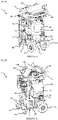
- the station 1 is advantageously in the form of a mobile carriage 1A which can be moved by an operator, for example in a garage.
- the carriage 1A comprises a structure 2, preferably metallic, comprising a base 3 on which are mounted the so-called “functional” elements, fulfilling the functions of recovery, recycling and recharging of refrigerant fluid as will be explained below .
- the terms “over”, “under”, “upper”, “lower”, “horizontal” and “vertical” are defined in relation to standard use of the station, i.e. when the station is placed flat on horizontal ground (i.e. parallel to the terrestrial horizontal), as illustrated on the figures 1 to 6 .
- the base 3 comprises an upper face and a lower face.
- the structure 2 comprises four wheels 4A, 4B, a tubular frame 5 mounted on the upper face of the base 3 and forming a handle 5A extending horizontally on one side of the carriage 1A in order to be able to handle it.
- the two wheels 4A located to the right of the handle 5A designated “rear wheels” are of greater width and diameter than the other two wheels 4B, designated “front wheels” in order to allow tilting of the carriage 1A on the two rear wheels 4A in order to be able to move it easily and pass obstacles such as, for example, pipes, steps, sidewalks, etc.
- Station 1 also comprises a plurality of panels 6, in particular an upper panel 6A, making it possible to close the side faces and the upper face of the carriage 1A in order to protect the functional elements mounted on the upper part of the base 3.
- Two front handles 7 are mounted on the upper panel 6A in order to be able to manipulate the station 1.
- the upper panel 6A also comprises in this example a printer 8 allowing the printing of the intervention and maintenance data generated by the station 1.
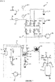
- station 1 comprises a low pressure inlet 10, a separator 20, a dehydration module 30, a condenser 40 and a tank 50, a load cell 60 of the reservoir 50, a vacuum pump 70, a high pressure outlet 80, a group of solenoid valves 90, an oil injection bottle 100, a tracer injection bottle 110, an oil recovery bottle 120 and a control module 130.
- a station according to the invention further comprises the other features forming part of independent claim 1.
- the aforementioned functional elements are connected to each other via pipes, in particular flexible, and the group of solenoid valves 90 so as to allow the station to operate according to several modes depending on the configuration of the solenoid valves of the group of solenoid valves 90.
- the low pressure inlet 10 is intended to be connected, via a pipe 11, to the low pressure outlet of the air conditioning module (not shown) from which it is desired to recover the refrigerant fluid and/or recharge with refrigerant fluid.
- a manometer 132 makes it possible to measure the pressure of refrigerant fluid circulating through the low pressure inlet 10.
- the separator 20 is capable of separating the refrigerant fluid and the oil recovered from the air conditioning module via the low pressure inlet.
- the separator 20 comprises a bottle 21 (or carboy) comprising a mixed inlet A IN, an outlet for hydrated fluid A OUT, an inlet for dehydrated fluid R IN, an outlet for dehydrated fluid R OUT, a coil 22 and an outlet for waste oil 23.
- the mixed inlet A IN is positioned in the upper part of the separator 20 and makes it possible to collect the refrigerant fluid and the used oil coming from the air conditioning module to which the station 1 is connected.
- the hydrated fluid outlet A OUT makes it possible to evacuate the refrigerant fluid from the bottle 21 to the dehydration module 30.
- the dehydrated fluid inlet R IN makes it possible to collect the dehydrated refrigerant fluid by the dehydration module 30.
- the coil 22 is connected between the dehydrated fluid inlet R IN and the dehydrated fluid outlet R OUT.
- the coil 22 is arranged in the lower part of the internal space of the bottle 21 and has the function of facilitating the evaporation of the hydrated fluid entered by the mixed inlet A IN and lowering the temperature of the fluid leaving the compressor 33 to facilitate the condensation of the fluid in the condenser 40.
- the dehydrated fluid outlet R OUT makes it possible to convey the dehydrated fluid having passed through the coil 22 to the condenser 40.
- the used oil outlet makes it possible to evacuate the used oil to the waste oil recovery bottle 120 via an EV13 recovery solenoid valve.
- the dehydration module 30 comprises a valve 31, a filter drier 32, a compressor 33, a compressor separator 34, a separation solenoid valve EV11, a safety pressure switch Pr and a non-return valve CL1.
- the valve 31 makes it possible to isolate the dehydrator 32 during maintenance, in particular when replacing the dehydrator 32.
- the safety pressure switch Pr makes it possible to interrupt the operation of the station 1, in particular to block the operation of all the equipment in operation when the pressure of the fluid in the internal circuit is too high in order to avoid any risk of explosion in the event of a fault in station 1.
- the filter drier 32 is connected to the separator 20 and has the function of absorbing the moisture contained in the refrigerant.
- the compressor 33 is connected to the filter drier 32 and makes it possible to circulate the refrigerant fluid through the dehydration module 30, in particular the filter drier 32 and the compressor separator 34.
- the compressor separator 34 is connected to the compressor 33 (via the connector port IN) and has the function of recovering the oil from the compressor 33 driven by the refrigerant in circulation.
- the compressor separator 34 is connected (via the OUT connector port) to the separator 20.
- the separation solenoid valve EV11 makes it possible to return the oil to the compressor 33 when the latter is stopped.
- the condenser 40 comprises a coil 40A through which the refrigerant fluid circulates in order to condense it.
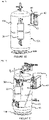
- the condenser 40 is mounted on the tank 50 via a bracket 42, for example metallic.
- the condenser 40 is said to be “ventilated” because it includes a fan 43 allowing the cooling fluid circulating in the coil 40A to be cooled.
- the condenser 40 is capable of condensing the refrigerant fluid separated by the separator 20.
- the tank 50 is in the form of a 50A bottle allowing both the recovery and storage of the refrigerant condensed by the condenser 40 and the storage of new refrigerant when the 50A bottle is changed or installed filled for the first time. .
- the bottle 50A also allows the supply of the stored refrigerant to recharge the air conditioning module of the vehicle.
- the carboy 50A comprises a side wall 50A1, on which the separator 20 and the condenser 40 are mounted, and a base 50B making it possible to mount the reservoir 50 on the weighing cell 60 in a stable manner.
- the tank is connected to the condenser 40 via a valve 51.
- an incondensables purge solenoid valve EV18 connected to the tank 50 via a valve 52 and a safety valve SP, for example set at 18 bars, making it possible to avoid overpressures in the tank 50 beyond the adjustment limit of said safety valve SP.
- a tank pressure sensor C2 is connected between the non-condensables purge solenoid valve EV18 and the valve 52 and makes it possible to measure the pressure of the fluid stored in the tank 50.
- the valve 52 is used in particular to allow the calibration of the pressure sensor tank C2.
- the weighing cell 60 is an electronic scale allowing for example weighing to the nearest gram.
- the separator 20 and the ventilated condenser 40 are mounted on the cylinder 50A which is placed on the weighing cell 60 so as to allow an overall weighing of both the liquid part of the refrigerant fluid stored in the separator 20, in the condenser 40 ventilated and in the tank 50A, and the liquid part of the refrigerant fluid stored or circulating in the pipe connecting the separator 20 to the ventilated condenser 40 and the pipe connecting the ventilated condenser 40 to the tank 50A.
- the separator 20 is mounted on a support 54.
- a heating belt 55 is placed around the tank 50 to regulate the temperature and therefore the pressure inside the tank 50.
- the vacuum pump 70 makes it possible in particular to create a vacuum and to remove the humidity in the internal circuit of station 1 and in the air conditioning module connected to station 1.
- the high pressure outlet 80 is intended to be connected, via a pipe 81, to the high pressure inlet of the air conditioning module.
- a pressure gauge 134 makes it possible to measure the pressure of refrigerant fluid circulating through the high pressure outlet 80.
- the group of solenoid valves 90 is connected to the low pressure inlet 10, to the separator 20, to the tank 50, to the vacuum pump 70 and to the high pressure outlet 80 in order to allow the operation of station 1 in different modes.
- the group of solenoid valves 90 comprises an interconnection box 91, called the "feeder”, to which are connected a high-pressure line solenoid valve module EV9, a low-pressure line solenoid valve module EV10, a solenoid valve module recovery valve EV12, a pumping solenoid valve module EV14, an oil injection solenoid valve EV15, a tracer injection solenoid valve EV16 and a refrigerant charge solenoid valve EV17 and a manifold pressure sensor C1 ( figure 7 ).
- the low pressure line solenoid valve module EV10 is connected to the low pressure inlet 10.
- the recovery solenoid valve module EV12 is connected to the separator 20.
- the high pressure line solenoid valve module EV9 is connected to the high outlet pressure 80.
- the pumping solenoid valve module EV14 is connected to the vacuum pump 70.
- the EV9 high pressure line solenoid valve module, EV10 low pressure line solenoid valve module, EV12 scavenge solenoid valve module, and EV14 pump solenoid valve module each include a first solenoid valve and a second solenoid valve connected head -spade. This makes it possible in particular to avoid, for the high pressure line solenoid valve module EV9 and the low pressure line solenoid valve module EV10, a return of refrigerant fluid from the air conditioning module to the interconnection box 91 of the group of solenoid valves 90.
- the oil injection solenoid valve EV15 is connected to the oil injection bottle 100.
- a non-return valve CL2 is arranged between the oil injection solenoid valve EV15 and the interconnection box 91 in order to avoid any return of fluid into the oil injection bottle 100.
- the tracer injection solenoid valve EV16 and a non-return valve CL3 are connected to a tracer injection bottle 110.
- the charging solenoid valve in refrigerant EV17 and a non-return valve CL4 are connected to tank 50 via a valve 53.
- Valve 53 is, in normal operation of station 1, always open but is switched to the closed position in order to close tank 50 on its phase. liquid in order to carry out maintenance operations.
- the control module 130 makes it possible in particular to control the solenoid valves of the group of solenoid valves 90 and to display the pressure at different places in the circuit.
- the control module 130 comprises in particular an LCD screen, an alphanumeric keypad, navigation keys, light-emitting diodes and emitters of sound signals (emitted for example when keys of the alphanumeric keypad are pressed or when station 1 has finished recharging the air conditioning module with refrigerant.
- an operator connects the low pressure inlet 10 of station 1 to the low pressure outlet of the vehicle air conditioning module and the high pressure outlet of station 1 to the high pressure inlet of the vehicle air conditioning module.
- the operator activates, via the control module 130, the coolant and waste oil recovery function.
- the control module 130 controls the opening of the high pressure line solenoid valve module EV9, the low pressure line solenoid valve module EV10 and the recovery solenoid valve module EV12, the other solenoid valves and control modules. solenoid valves being closed.
- the refrigerant fluid and used oil contained in the circuit of the air conditioning module of the vehicle are conveyed to the separator 20 successively via the low pressure inlet 10, the low pressure line solenoid valve module EV10 and the solenoid valve module of recovery EV12 and the A IN input of splitter 20.
- a separation step E2 the used oil falls to the bottom of the separator 20 while the refrigerant fluid is absorbed by the outlet A OUT under the action of the compressor 33 and is routed to the filter drier 32.
- the filter drier 32 then absorbs moisture from the refrigerant fluid which is then routed to the compressor separator 34.
- the accumulation of oil from the compressor 33 in the compressor separator 34 increases the pressure in the separator 20.
- the separation solenoid valve EV11 can be controlled by the control module 130 in opening, periodically and in jerks, for example three or four times every 10 seconds, in order to convey the oil from the compressor separator 34 to the compressor 33 and thus reduce the pressure in the separator 20, this pressure being measured by the feed pressure sensor C1. More precisely, the measurement of the pressure in the separator 20 by the feed pressure sensor C1 allows the control module 130 to control the pressure in the separator 20 so that it remains low, for example of the order of 0.3 bar.
- the low pressure in the separator 20 avoids propelling a large quantity of refrigerant fluid into the atmosphere, thus reducing the quantity of polluting gas discharged into the atmosphere compared to previous solutions which evacuate the used oil towards the used oil collection bottle 120 at high pressure and therefore in large quantities.
- the refrigerant fluid leaving the coil 22 is conveyed to the condenser 40 which transforms the gaseous part into liquid in order to store it in the tank 50 in a step E3 of condensation.
- the weighing cell 60 weighs, in a step E4, the assembly formed by the tank 50, the separator 20, the condenser 40 as well as the pipes connecting them two to of them.
- This overall weighing makes it possible to weigh all of the refrigerant liquid which circulates or is stored in the tank 50, in the separator 20, in the condenser 40 as well as in the pipes connecting them two by two.
- the control module 130 deduces therefrom the weight of the liquid coolant recovered in order to ensure that the load limit of tank 50 is not in danger of being exceeded, which could increase the internal pressure of tank 50 beyond a limit for which a risk of explosion of tank 50 is possible.
- a step E5 of emptying the internal circuit of the station 1 is carried out in a so-called “vacuuming” mode.
- This step consists of opening the pumping solenoid valve module EV14, the high pressure line solenoid valve module EV9 and the low pressure line solenoid valve module EV10, the other solenoid valves and solenoid valve modules being closed, in order to lowering the pressure of the internal circuit to a negative value, for example to a value of the order of ⁇ 20 bars.
- the tracer injection solenoid valve EV16 can be opened if necessary in order to inject, from the tracer injection bottle 110, an ultraviolet tracer into the air conditioning module during a step E7 in order to detect a leak said air conditioning module from an ultraviolet lamp (so-called “tracer injection” mode).
- a non-condensable purge step can be performed by opening the purge solenoid valve non-condensables EV18 mounted on tank 50, the other solenoid valves and solenoid valve modules being closed (so-called “non-condensables purge” mode).
- the oil injection solenoid valve EV15 and, if applicable, the tracer injection solenoid valve EV16 are closed, then the refrigerant charge solenoid valve EV17 and the valve 53 are open in order to allow recharging of the air conditioning module with refrigerant fluid during a step E8 in a so-called “recharging” mode.
- the control module 130 positions or maintains the valve 31 in the open position, as does the recovery solenoid valve module EV12, and activates the compressor 33 in order to evacuate the refrigerant from the group of solenoid valves 90, from the dehydration module 30 and from the separator 20 to the reservoir 50.
- the control module 130 then places the valve 31 in the closed position.
- the maintenance operator can then dismantle and replace the filter drier 32. Once the replacement has been made, the control module 130 reopens the valve 31 and activates the vacuum pump 70 in order to expel the air and the humidity towards the outside, the circuit then being under vacuum.
- the arrangement of the separator 20 and the condenser 40 on the tank 50 therefore advantageously makes it possible to weigh precisely and at any time the weight of coolant liquid contained in the station 1 in order to ensure that the limiting volume of coolant liquid in the tank 50 is not exceeded.
- such an arrangement advantageously makes it possible to precisely determine the quantity of refrigerant fluid recovered from the air conditioning module.
Landscapes
- Engineering & Computer Science (AREA)
- Physics & Mathematics (AREA)
- Mechanical Engineering (AREA)
- Thermal Sciences (AREA)
- General Engineering & Computer Science (AREA)
- Chemical & Material Sciences (AREA)
- Analytical Chemistry (AREA)
- Power Engineering (AREA)
- Air-Conditioning For Vehicles (AREA)
- Gas Separation By Absorption (AREA)
- Sorption Type Refrigeration Machines (AREA)
Claims (10)
- Station (1) zur Rückgewinnung, zum Recycling und zum Nachfüllen eines Kühlfluids eines Kühlmoduls, wobei die Station (1) einen inneren Zirkulationskreis des Kühlfluids umfasst, wobei der innere Kreis umfasst:- einen Niederdruckeinlass (10), der bestimmt ist, mit dem Niederdruckauslass des Kühlmoduls verbunden zu sein,- einen Separator (20), der imstande ist, das durch den Niederdruckeinlass (10) Kühlfluid und das Öl, die zurückgewonnen wurden, des Kühlmoduls zu trennen,- einen Kondensator (40), der imstande ist, das vom Separator (20) getrennte Kühlfluid zu kondensieren,- einen Vorratsbehälter (50) des Kühlfluids,- eine Wägezelle (60), auf der der Behälter (50) angebracht ist und die imstande ist, den Behälter (50) zu wiegen,- einen Hochdruckauslass (80), der bestimmt ist, mit dem Hochdruckeinlass des Kühlmoduls verbunden zu sein,- eine Magnetventilgruppe (90), die mit dem Niederdruckeinlass (10), dem Separator (20), dem Kondensator (40), dem Behälter (50) und dem Hochdruckauslass (80) verbunden ist, um den Betrieb der Station (1) in mindestens einem Rückgewinnungsmodus und einem Nachfüllmodus zu erlauben, wobei die Station (1) dadurch gekennzeichnet ist, dass der Separator (20) und der Kondensator (40) auf dem Behälter (50) angebracht sind.
- Station (1) nach Anspruch 1, wobei, wobei der Behälter (50) in Form eines Ballons (50A) vorliegt, der Kondensator (40) im oberen Teil des Ballons (50A) befestigt ist.
- Station (1) nach einem der vorangehenden Ansprüche, wobei, wobei der Behälter (50) in Form eines Ballons (50A) vorliegt, der eine Seitenwand (50A1) aufweist, der Separator (20) an der Seitenwand (50A1) befestigt ist.
- Station (1) nach einem der vorangehenden Ansprüche, die ferner ein Entwässerungsmodul (30) umfasst, wobei das Entwässerungsmodul (30) umfasst:- einen Entwässerungsfilter (32), der mit dem Separator (20) verbunden ist,- einen Kompressor (33), der mit dem Entwässerungsfilter (32) verbunden ist,- einen Separator-Kompressor (34), der zum einem mit dem Kompressor (33) und zum anderen mit dem Separator (20) verbunden ist.
- Station (1) nach einem der vorangehenden Ansprüche, die eine Vakuumpumpe (70) umfasst, die imstande ist, im inneren Kreis der Station (1) das Vakuum zu erzeugen.
- Station nach einem der vorangehenden Ansprüche, wobei die Magnetventilgruppe (90) umfasst:- ein Hochdruckleitungs-Magnetventilmodul (EV9), das mit dem Hochdruckauslass (80) verbunden ist,- ein Niederdruckleitungs-Magnetventilmodul (EV10), das mit dem Niederdruckeinlass (10) verbunden ist,- ein Rückgewinnungs-Magnetventilmodul (EV12), das mit dem Separator (20) verbunden ist,- ein Magnetventil zum Füllen mit Kühlmittel (EV17), das mit dem Behälter (50) verbunden ist.
- Station (1) nach vorangehendem Anspruch, wobei das Hochdruckleitungs-Magnetventilmodul (EV9), das Niederdruckleitungs-Magnetventilmodul (EV10) und das Rückgewinnungs-Magnetventilmodul (EV12) jeweils ein erstes Magnetventil und ein zweites Magnetventil umfassen, die verkehrt verbunden sind.
- Station (1) nach einem der vorangehenden Ansprüche, die ein Steuermodul (130) umfasst, das imstande ist, die Magnetventilgruppe (90) zu steuern.
- Verfahren zum Wiegen einer Kühlflüssigkeit in einer Station (1) zur Rückgewinnung und zum Nachfüllen eines Kühlfluids eines Kühlmoduls, wobei die Station (1) einen Kühlflüssigkeits-Vorratsbehälter (50), einen Separator (20), der zum Trennen des Kühlfluids vom Altöl des Kühlmoduls, die zurückgewonnenen wurden, geeignet ist, einen Kondensator (40), der imstande ist, das Kühlfluid zu kondensieren, das vom Separator (20) getrennt wurde, mindestens eine Leitung, die den Separator (20) und den Kondensator (40) verbindet, mindestens eine Leitung, die den Kondensator (40) und den Behälter (50) verbindet, wobei das Verfahren einen Rückgewinnungsschritt (E1) des Kühlfluids und des Öls des Kühlmoduls, einen Trennungsschritt (E2) des Kühlfluids und des Öls, die vom Kühlmodul zurückgewonnen wurden, einen Kondensationsschritt (E3) des gasförmigen Teils des getrennten Kühlfluids umfasst, wobei das Verfahren dadurch gekennzeichnet ist, dass es einen kontinuierlichen Wägeschritt (E4) durch eine einzige Wägezelle (60) des Behälters (50), des Separators (20), des Kondensators (40) und der Leitungen, die sie während des Rückgewinnungsschritts verbinden, umfasst.
- Verfahren nach vorangehendem Anspruch, wobei die Station (1) ferner ein Entwässerungsmodul (30) und eine Magnetventilgruppe (90) umfasst, die ein Rückgewinnungs-Magnetventilmodul (EV12) umfasst, wobei das Entwässerungsmodul (30) einen Schieber (31), einen Entwässerungsfilter (32), der mit dem Schieber (31) verbunden ist, einen Kompressor (33), der mit dem Entwässerungsfilter (32) verbunden ist und einen Separator-Kompressor (34), der zum einen mit dem Eingang des Kompressors (33) und mit dem Ausgang des Kompressors (33) und zum anderen mit dem Separator (20) verbunden ist, umfasst, wobei das Verfahren, wobei der Schieber (31) und das Rückgewinnungs-Magnetventilmodul (EV12) in geöffneter Stellung sind, einen Aktivierungsschritt des Kompressors (33) umfasst, um das Kühlfluid aus der Magnetventilgruppe (90), dem Entwässerungsmodul (30) und dem Separator (20) bis zum Behälter (50) abzuleiten, einen Schließschritt des Schiebers (31), einen Wartungsschritt des Entwässerungsfilters (32), einen Öffnungsschritt des Schiebers (31) und einen Aktivierungsschritt der Vakuumpumpe (70), um die Luft und die Feuchtigkeit nach außen abzuleiten, wobei der Kreis dann im Vakuum ist.
Applications Claiming Priority (1)
| Application Number | Priority Date | Filing Date | Title |
|---|---|---|---|
| FR1900226A FR3091752B1 (fr) | 2019-01-10 | 2019-01-10 | Station de récuperation et de recharge d’un fluide refrigérant |
Publications (2)
| Publication Number | Publication Date |
|---|---|
| EP3680582A1 EP3680582A1 (de) | 2020-07-15 |
| EP3680582B1 true EP3680582B1 (de) | 2022-11-02 |
Family
ID=66690638
Family Applications (1)
| Application Number | Title | Priority Date | Filing Date |
|---|---|---|---|
| EP20150791.0A Active EP3680582B1 (de) | 2019-01-10 | 2020-01-08 | Station zur rückgewinnung und zum wiederaufladen einer kühlflüssigkeit und assoziiertes verfahren |
Country Status (3)
| Country | Link |
|---|---|
| EP (1) | EP3680582B1 (de) |
| ES (1) | ES2937110T3 (de) |
| FR (1) | FR3091752B1 (de) |
Families Citing this family (2)
| Publication number | Priority date | Publication date | Assignee | Title |
|---|---|---|---|---|
| CN117490290A (zh) * | 2023-11-28 | 2024-02-02 | 深圳市易检车服科技有限公司 | 一种集成式冷媒油气分离装置 |
| CN223340603U (zh) * | 2024-09-14 | 2025-09-16 | 深圳市易检车服科技有限公司 | 一种汽车空调保养设备 |
Family Cites Families (5)
| Publication number | Priority date | Publication date | Assignee | Title |
|---|---|---|---|---|
| US4768347A (en) * | 1987-11-04 | 1988-09-06 | Kent-Moore Corporation | Refrigerant recovery and purification system |
| US5161385A (en) * | 1991-03-18 | 1992-11-10 | Schumacher Ernest W | Refrigerant recovery and recycle system with flexible storage bag |
| US7726137B2 (en) * | 2006-06-30 | 2010-06-01 | Spx Corporation | Method and apparatus for refrigerant recovery unit filter dryer maintenance |
| DE202013004158U1 (de) * | 2013-05-06 | 2014-08-07 | Dometic Sweden Ab | Service-Gerät zum Warten von Fahrzeugklimaanlagen |
| EP3162599A1 (de) * | 2015-10-27 | 2017-05-03 | Brain Bee S.P.A. | Verfahren und vorrichtung zum rückgewinnen und wiederauffüllen von kältemittel in kraftfahrzeugen mit ölrückgewinnung |
-
2019
- 2019-01-10 FR FR1900226A patent/FR3091752B1/fr active Active
-
2020
- 2020-01-08 EP EP20150791.0A patent/EP3680582B1/de active Active
- 2020-01-08 ES ES20150791T patent/ES2937110T3/es active Active
Also Published As
| Publication number | Publication date |
|---|---|
| ES2937110T3 (es) | 2023-03-24 |
| FR3091752B1 (fr) | 2021-05-28 |
| FR3091752A1 (fr) | 2020-07-17 |
| EP3680582A1 (de) | 2020-07-15 |
Similar Documents
| Publication | Publication Date | Title |
|---|---|---|
| EP3680582B1 (de) | Station zur rückgewinnung und zum wiederaufladen einer kühlflüssigkeit und assoziiertes verfahren | |
| EP4153900B1 (de) | Vorrichtung und verfahren zur übertragung einer kryogenen flüssigkeit | |
| US7832222B2 (en) | Background tank fill based on refrigerant composition | |
| EP2573338B1 (de) | Überfüllungskontrolle eines Schmiersystems für einen Flugzeugmotor | |
| EP2370279B1 (de) | Vorrichtung zum kühlen der batterien eines fahrzeugs, insbesondere eines elektrofahrzeugs, und mit solch einer vorrichtung versehenes fahrzeug | |
| EP3851731B1 (de) | Station und verfahren zum füllen von behältern | |
| US6442963B1 (en) | Non-condensable purge technique using refrigerant temperature offset | |
| WO2021116629A1 (fr) | Dispositif de refroidissement d'un pack-batteries | |
| FR2934087A3 (fr) | Systeme et procede de refroidissement d'une batterie de vehicule electrique, batterie et station de refroidissement d'une batterie | |
| FR3095691A1 (fr) | Station de récupération et de recharge d’un fluide réfrigérant | |
| FR2712672A1 (fr) | Système de réfrigération pour moyens de transport. | |
| FR2904099A1 (fr) | Systeme de refroidissement transcritique et procede pour son rechargement automatique | |
| EP2034258B1 (de) | Verfahren und Vorrichtung zum Ölausgleich zwischen Kompressoren | |
| FR2928907A1 (fr) | Appareil de distribution de boisson muni d'un element caloporteur | |
| WO2022084071A1 (fr) | Procédé et système de transfert d'hydrogène cryogénique | |
| EP3488139A1 (de) | Modul und system zur druckentlastung eines kryogenen tanks | |
| FR2963285A1 (fr) | Dispositif de remplissage et vehicule automobile equipe d'un tel dispositif de remplissage | |
| EP2149758A1 (de) | Verfahren zur Frostschutz eines Heizanlages und zugehörige Heizanlage | |
| EP3899347B1 (de) | Anordnung zum befüllen eines flüssigen sauerstoffbehälters eines unterseebootes und zugehöriges füllverfahren | |
| FR3073608A1 (fr) | Procede de refroidissement d'un condenseur de systeme de climatisation pour vehicule automobile | |
| JP5958409B2 (ja) | ベーパ回収装置 | |
| WO2022003035A1 (fr) | Dispositif de régulation thermique | |
| FR3130358A1 (fr) | Circuit de refroidissement pour système d’alimentation et de refroidissement d’un gaz | |
| EP2948665B1 (de) | Kältekreislauf-konditionierungssystem | |
| FR2787507A1 (fr) | Appareil de remplacement du liquide de refroidissement |
Legal Events
| Date | Code | Title | Description |
|---|---|---|---|
| PUAI | Public reference made under article 153(3) epc to a published international application that has entered the european phase |
Free format text: ORIGINAL CODE: 0009012 |
|
| STAA | Information on the status of an ep patent application or granted ep patent |
Free format text: STATUS: THE APPLICATION HAS BEEN PUBLISHED |
|
| AK | Designated contracting states |
Kind code of ref document: A1 Designated state(s): AL AT BE BG CH CY CZ DE DK EE ES FI FR GB GR HR HU IE IS IT LI LT LU LV MC MK MT NL NO PL PT RO RS SE SI SK SM TR |
|
| AX | Request for extension of the european patent |
Extension state: BA ME |
|
| STAA | Information on the status of an ep patent application or granted ep patent |
Free format text: STATUS: REQUEST FOR EXAMINATION WAS MADE |
|
| 17P | Request for examination filed |
Effective date: 20210118 |
|
| RBV | Designated contracting states (corrected) |
Designated state(s): AL AT BE BG CH CY CZ DE DK EE ES FI FR GB GR HR HU IE IS IT LI LT LU LV MC MK MT NL NO PL PT RO RS SE SI SK SM TR |
|
| GRAP | Despatch of communication of intention to grant a patent |
Free format text: ORIGINAL CODE: EPIDOSNIGR1 |
|
| RIC1 | Information provided on ipc code assigned before grant |
Ipc: F25B 41/40 20210101ALI20220517BHEP Ipc: F25B 41/20 20210101ALI20220517BHEP Ipc: F25B 45/00 20060101ALI20220517BHEP Ipc: F25B 43/02 20060101ALI20220517BHEP Ipc: F25B 43/00 20060101ALI20220517BHEP Ipc: F25B 41/00 20060101AFI20220517BHEP |
|
| STAA | Information on the status of an ep patent application or granted ep patent |
Free format text: STATUS: GRANT OF PATENT IS INTENDED |
|
| INTG | Intention to grant announced |
Effective date: 20220623 |
|
| GRAS | Grant fee paid |
Free format text: ORIGINAL CODE: EPIDOSNIGR3 |
|
| GRAA | (expected) grant |
Free format text: ORIGINAL CODE: 0009210 |
|
| STAA | Information on the status of an ep patent application or granted ep patent |
Free format text: STATUS: THE PATENT HAS BEEN GRANTED |
|
| AK | Designated contracting states |
Kind code of ref document: B1 Designated state(s): AL AT BE BG CH CY CZ DE DK EE ES FI FR GB GR HR HU IE IS IT LI LT LU LV MC MK MT NL NO PL PT RO RS SE SI SK SM TR |
|
| REG | Reference to a national code |
Ref country code: GB Ref legal event code: FG4D Free format text: NOT ENGLISH |
|
| REG | Reference to a national code |
Ref country code: CH Ref legal event code: EP Ref country code: AT Ref legal event code: REF Ref document number: 1529011 Country of ref document: AT Kind code of ref document: T Effective date: 20221115 |
|
| REG | Reference to a national code |
Ref country code: DE Ref legal event code: R096 Ref document number: 602020005940 Country of ref document: DE |
|
| REG | Reference to a national code |
Ref country code: IE Ref legal event code: FG4D Free format text: LANGUAGE OF EP DOCUMENT: FRENCH |
|
| REG | Reference to a national code |
Ref country code: NL Ref legal event code: FP |
|
| REG | Reference to a national code |
Ref country code: LT Ref legal event code: MG9D |
|
| RAP2 | Party data changed (patent owner data changed or rights of a patent transferred) |
Owner name: FRANCE CLIM INVEST Owner name: SOCIETE NOUVELLE DE CLIMATISATION (SNDC) |
|
| REG | Reference to a national code |
Ref country code: ES Ref legal event code: FG2A Ref document number: 2937110 Country of ref document: ES Kind code of ref document: T3 Effective date: 20230324 |
|
| REG | Reference to a national code |
Ref country code: AT Ref legal event code: MK05 Ref document number: 1529011 Country of ref document: AT Kind code of ref document: T Effective date: 20221102 |
|
| PG25 | Lapsed in a contracting state [announced via postgrant information from national office to epo] |
Ref country code: SE Free format text: LAPSE BECAUSE OF FAILURE TO SUBMIT A TRANSLATION OF THE DESCRIPTION OR TO PAY THE FEE WITHIN THE PRESCRIBED TIME-LIMIT Effective date: 20221102 Ref country code: PT Free format text: LAPSE BECAUSE OF FAILURE TO SUBMIT A TRANSLATION OF THE DESCRIPTION OR TO PAY THE FEE WITHIN THE PRESCRIBED TIME-LIMIT Effective date: 20230302 Ref country code: NO Free format text: LAPSE BECAUSE OF FAILURE TO SUBMIT A TRANSLATION OF THE DESCRIPTION OR TO PAY THE FEE WITHIN THE PRESCRIBED TIME-LIMIT Effective date: 20230202 Ref country code: LT Free format text: LAPSE BECAUSE OF FAILURE TO SUBMIT A TRANSLATION OF THE DESCRIPTION OR TO PAY THE FEE WITHIN THE PRESCRIBED TIME-LIMIT Effective date: 20221102 Ref country code: FI Free format text: LAPSE BECAUSE OF FAILURE TO SUBMIT A TRANSLATION OF THE DESCRIPTION OR TO PAY THE FEE WITHIN THE PRESCRIBED TIME-LIMIT Effective date: 20221102 Ref country code: AT Free format text: LAPSE BECAUSE OF FAILURE TO SUBMIT A TRANSLATION OF THE DESCRIPTION OR TO PAY THE FEE WITHIN THE PRESCRIBED TIME-LIMIT Effective date: 20221102 |
|
| PG25 | Lapsed in a contracting state [announced via postgrant information from national office to epo] |
Ref country code: RS Free format text: LAPSE BECAUSE OF FAILURE TO SUBMIT A TRANSLATION OF THE DESCRIPTION OR TO PAY THE FEE WITHIN THE PRESCRIBED TIME-LIMIT Effective date: 20221102 Ref country code: PL Free format text: LAPSE BECAUSE OF FAILURE TO SUBMIT A TRANSLATION OF THE DESCRIPTION OR TO PAY THE FEE WITHIN THE PRESCRIBED TIME-LIMIT Effective date: 20221102 Ref country code: LV Free format text: LAPSE BECAUSE OF FAILURE TO SUBMIT A TRANSLATION OF THE DESCRIPTION OR TO PAY THE FEE WITHIN THE PRESCRIBED TIME-LIMIT Effective date: 20221102 Ref country code: IS Free format text: LAPSE BECAUSE OF FAILURE TO SUBMIT A TRANSLATION OF THE DESCRIPTION OR TO PAY THE FEE WITHIN THE PRESCRIBED TIME-LIMIT Effective date: 20230302 Ref country code: HR Free format text: LAPSE BECAUSE OF FAILURE TO SUBMIT A TRANSLATION OF THE DESCRIPTION OR TO PAY THE FEE WITHIN THE PRESCRIBED TIME-LIMIT Effective date: 20221102 Ref country code: GR Free format text: LAPSE BECAUSE OF FAILURE TO SUBMIT A TRANSLATION OF THE DESCRIPTION OR TO PAY THE FEE WITHIN THE PRESCRIBED TIME-LIMIT Effective date: 20230203 |
|
| PG25 | Lapsed in a contracting state [announced via postgrant information from national office to epo] |
Ref country code: SM Free format text: LAPSE BECAUSE OF FAILURE TO SUBMIT A TRANSLATION OF THE DESCRIPTION OR TO PAY THE FEE WITHIN THE PRESCRIBED TIME-LIMIT Effective date: 20221102 Ref country code: RO Free format text: LAPSE BECAUSE OF FAILURE TO SUBMIT A TRANSLATION OF THE DESCRIPTION OR TO PAY THE FEE WITHIN THE PRESCRIBED TIME-LIMIT Effective date: 20221102 Ref country code: EE Free format text: LAPSE BECAUSE OF FAILURE TO SUBMIT A TRANSLATION OF THE DESCRIPTION OR TO PAY THE FEE WITHIN THE PRESCRIBED TIME-LIMIT Effective date: 20221102 Ref country code: DK Free format text: LAPSE BECAUSE OF FAILURE TO SUBMIT A TRANSLATION OF THE DESCRIPTION OR TO PAY THE FEE WITHIN THE PRESCRIBED TIME-LIMIT Effective date: 20221102 Ref country code: CZ Free format text: LAPSE BECAUSE OF FAILURE TO SUBMIT A TRANSLATION OF THE DESCRIPTION OR TO PAY THE FEE WITHIN THE PRESCRIBED TIME-LIMIT Effective date: 20221102 |
|
| REG | Reference to a national code |
Ref country code: DE Ref legal event code: R097 Ref document number: 602020005940 Country of ref document: DE |
|
| PG25 | Lapsed in a contracting state [announced via postgrant information from national office to epo] |
Ref country code: SK Free format text: LAPSE BECAUSE OF FAILURE TO SUBMIT A TRANSLATION OF THE DESCRIPTION OR TO PAY THE FEE WITHIN THE PRESCRIBED TIME-LIMIT Effective date: 20221102 Ref country code: AL Free format text: LAPSE BECAUSE OF FAILURE TO SUBMIT A TRANSLATION OF THE DESCRIPTION OR TO PAY THE FEE WITHIN THE PRESCRIBED TIME-LIMIT Effective date: 20221102 |
|
| REG | Reference to a national code |
Ref country code: CH Ref legal event code: PL |
|
| PLBE | No opposition filed within time limit |
Free format text: ORIGINAL CODE: 0009261 |
|
| STAA | Information on the status of an ep patent application or granted ep patent |
Free format text: STATUS: NO OPPOSITION FILED WITHIN TIME LIMIT |
|
| PG25 | Lapsed in a contracting state [announced via postgrant information from national office to epo] |
Ref country code: LU Free format text: LAPSE BECAUSE OF NON-PAYMENT OF DUE FEES Effective date: 20230108 |
|
| REG | Reference to a national code |
Ref country code: BE Ref legal event code: MM Effective date: 20230131 |
|
| 26N | No opposition filed |
Effective date: 20230803 |
|
| PG25 | Lapsed in a contracting state [announced via postgrant information from national office to epo] |
Ref country code: LI Free format text: LAPSE BECAUSE OF NON-PAYMENT OF DUE FEES Effective date: 20230131 Ref country code: CH Free format text: LAPSE BECAUSE OF NON-PAYMENT OF DUE FEES Effective date: 20230131 |
|
| PG25 | Lapsed in a contracting state [announced via postgrant information from national office to epo] |
Ref country code: SI Free format text: LAPSE BECAUSE OF FAILURE TO SUBMIT A TRANSLATION OF THE DESCRIPTION OR TO PAY THE FEE WITHIN THE PRESCRIBED TIME-LIMIT Effective date: 20221102 Ref country code: BE Free format text: LAPSE BECAUSE OF NON-PAYMENT OF DUE FEES Effective date: 20230131 |
|
| PG25 | Lapsed in a contracting state [announced via postgrant information from national office to epo] |
Ref country code: IE Free format text: LAPSE BECAUSE OF NON-PAYMENT OF DUE FEES Effective date: 20230108 |
|
| PG25 | Lapsed in a contracting state [announced via postgrant information from national office to epo] |
Ref country code: MC Free format text: LAPSE BECAUSE OF FAILURE TO SUBMIT A TRANSLATION OF THE DESCRIPTION OR TO PAY THE FEE WITHIN THE PRESCRIBED TIME-LIMIT Effective date: 20221102 |
|
| PG25 | Lapsed in a contracting state [announced via postgrant information from national office to epo] |
Ref country code: MC Free format text: LAPSE BECAUSE OF FAILURE TO SUBMIT A TRANSLATION OF THE DESCRIPTION OR TO PAY THE FEE WITHIN THE PRESCRIBED TIME-LIMIT Effective date: 20221102 |
|
| PG25 | Lapsed in a contracting state [announced via postgrant information from national office to epo] |
Ref country code: BG Free format text: LAPSE BECAUSE OF FAILURE TO SUBMIT A TRANSLATION OF THE DESCRIPTION OR TO PAY THE FEE WITHIN THE PRESCRIBED TIME-LIMIT Effective date: 20221102 |
|
| PG25 | Lapsed in a contracting state [announced via postgrant information from national office to epo] |
Ref country code: BG Free format text: LAPSE BECAUSE OF FAILURE TO SUBMIT A TRANSLATION OF THE DESCRIPTION OR TO PAY THE FEE WITHIN THE PRESCRIBED TIME-LIMIT Effective date: 20221102 |
|
| PG25 | Lapsed in a contracting state [announced via postgrant information from national office to epo] |
Ref country code: CY Free format text: LAPSE BECAUSE OF FAILURE TO SUBMIT A TRANSLATION OF THE DESCRIPTION OR TO PAY THE FEE WITHIN THE PRESCRIBED TIME-LIMIT; INVALID AB INITIO Effective date: 20200108 |
|
| PG25 | Lapsed in a contracting state [announced via postgrant information from national office to epo] |
Ref country code: HU Free format text: LAPSE BECAUSE OF FAILURE TO SUBMIT A TRANSLATION OF THE DESCRIPTION OR TO PAY THE FEE WITHIN THE PRESCRIBED TIME-LIMIT; INVALID AB INITIO Effective date: 20200108 |
|
| PG25 | Lapsed in a contracting state [announced via postgrant information from national office to epo] |
Ref country code: TR Free format text: LAPSE BECAUSE OF FAILURE TO SUBMIT A TRANSLATION OF THE DESCRIPTION OR TO PAY THE FEE WITHIN THE PRESCRIBED TIME-LIMIT Effective date: 20221102 |
|
| PGFP | Annual fee paid to national office [announced via postgrant information from national office to epo] |
Ref country code: NL Payment date: 20260121 Year of fee payment: 7 |
|
| PGFP | Annual fee paid to national office [announced via postgrant information from national office to epo] |
Ref country code: GB Payment date: 20260123 Year of fee payment: 7 |
|
| PGFP | Annual fee paid to national office [announced via postgrant information from national office to epo] |
Ref country code: ES Payment date: 20260227 Year of fee payment: 7 |
|
| PGFP | Annual fee paid to national office [announced via postgrant information from national office to epo] |
Ref country code: DE Payment date: 20260121 Year of fee payment: 7 |
|
| PGFP | Annual fee paid to national office [announced via postgrant information from national office to epo] |
Ref country code: IT Payment date: 20260126 Year of fee payment: 7 |
|
| PGFP | Annual fee paid to national office [announced via postgrant information from national office to epo] |
Ref country code: FR Payment date: 20260116 Year of fee payment: 7 |