EP3680652B1 - Système d'étalonnage d'inspection de liaison au laser - Google Patents
Système d'étalonnage d'inspection de liaison au laser Download PDFInfo
- Publication number
- EP3680652B1 EP3680652B1 EP19196534.2A EP19196534A EP3680652B1 EP 3680652 B1 EP3680652 B1 EP 3680652B1 EP 19196534 A EP19196534 A EP 19196534A EP 3680652 B1 EP3680652 B1 EP 3680652B1
- Authority
- EP
- European Patent Office
- Prior art keywords
- calibration
- laser
- panel
- motion sensor
- compression wave
- Prior art date
- Legal status (The legal status is an assumption and is not a legal conclusion. Google has not performed a legal analysis and makes no representation as to the accuracy of the status listed.)
- Active
Links
Images



Classifications
-
- G—PHYSICS
- G01—MEASURING; TESTING
- G01N—INVESTIGATING OR ANALYSING MATERIALS BY DETERMINING THEIR CHEMICAL OR PHYSICAL PROPERTIES
- G01N29/00—Investigating or analysing materials by the use of ultrasonic, sonic or infrasonic waves; Visualisation of the interior of objects by transmitting ultrasonic or sonic waves through the object
- G01N29/04—Analysing solids
- G01N29/11—Analysing solids by measuring attenuation of acoustic waves
-
- G—PHYSICS
- G01—MEASURING; TESTING
- G01N—INVESTIGATING OR ANALYSING MATERIALS BY DETERMINING THEIR CHEMICAL OR PHYSICAL PROPERTIES
- G01N29/00—Investigating or analysing materials by the use of ultrasonic, sonic or infrasonic waves; Visualisation of the interior of objects by transmitting ultrasonic or sonic waves through the object
- G01N29/22—Details, e.g. general constructional or apparatus details
- G01N29/30—Arrangements for calibrating or comparing, e.g. with standard objects
-
- G—PHYSICS
- G01—MEASURING; TESTING
- G01N—INVESTIGATING OR ANALYSING MATERIALS BY DETERMINING THEIR CHEMICAL OR PHYSICAL PROPERTIES
- G01N29/00—Investigating or analysing materials by the use of ultrasonic, sonic or infrasonic waves; Visualisation of the interior of objects by transmitting ultrasonic or sonic waves through the object
- G01N29/04—Analysing solids
- G01N29/041—Analysing solids on the surface of the material, e.g. using Lamb, Rayleigh or shear waves
-
- G—PHYSICS
- G01—MEASURING; TESTING
- G01N—INVESTIGATING OR ANALYSING MATERIALS BY DETERMINING THEIR CHEMICAL OR PHYSICAL PROPERTIES
- G01N29/00—Investigating or analysing materials by the use of ultrasonic, sonic or infrasonic waves; Visualisation of the interior of objects by transmitting ultrasonic or sonic waves through the object
- G01N29/04—Analysing solids
- G01N29/043—Analysing solids in the interior, e.g. by shear waves
-
- G—PHYSICS
- G01—MEASURING; TESTING
- G01N—INVESTIGATING OR ANALYSING MATERIALS BY DETERMINING THEIR CHEMICAL OR PHYSICAL PROPERTIES
- G01N29/00—Investigating or analysing materials by the use of ultrasonic, sonic or infrasonic waves; Visualisation of the interior of objects by transmitting ultrasonic or sonic waves through the object
- G01N29/22—Details, e.g. general constructional or apparatus details
- G01N29/24—Probes
- G01N29/2412—Probes using the magnetostrictive properties of the material to be examined, e.g. electromagnetic acoustic transducers [EMAT]
-
- G—PHYSICS
- G01—MEASURING; TESTING
- G01N—INVESTIGATING OR ANALYSING MATERIALS BY DETERMINING THEIR CHEMICAL OR PHYSICAL PROPERTIES
- G01N29/00—Investigating or analysing materials by the use of ultrasonic, sonic or infrasonic waves; Visualisation of the interior of objects by transmitting ultrasonic or sonic waves through the object
- G01N29/22—Details, e.g. general constructional or apparatus details
- G01N29/24—Probes
- G01N29/2418—Probes using optoacoustic interaction with the material, e.g. laser radiation, photoacoustics
-
- G—PHYSICS
- G01—MEASURING; TESTING
- G01N—INVESTIGATING OR ANALYSING MATERIALS BY DETERMINING THEIR CHEMICAL OR PHYSICAL PROPERTIES
- G01N2291/00—Indexing codes associated with group G01N29/00
- G01N2291/04—Wave modes and trajectories
- G01N2291/042—Wave modes
- G01N2291/0421—Longitudinal waves
-
- G—PHYSICS
- G01—MEASURING; TESTING
- G01N—INVESTIGATING OR ANALYSING MATERIALS BY DETERMINING THEIR CHEMICAL OR PHYSICAL PROPERTIES
- G01N2291/00—Indexing codes associated with group G01N29/00
- G01N2291/26—Scanned objects
- G01N2291/267—Welds
Definitions
- the present disclosure relates generally to test structure inspection, and more particularly to the calibration of inspection systems used to evaluate the strength of a test structure.
- Laser inspection systems e.g., Laser Bond Inspection (LBI) systems
- LBI Laser Bond Inspection
- an LBI system may evaluate whether a structure, such as a unitized panel used to construct an airplane, has process flaws and/or is sufficiently strong for its intended use.
- an LBI system may evaluate whether a bond securing two structures together is sufficiently strong to maintain the bond during specified operating conditions. To ensure the accuracy of such strength evaluations, such inspection systems are calibrated.
- US 2016/131557 A1 in accordance with its abstract, states that a method for creation of a non-destructive inspection (NDI) standard employs a coupon of bonded layers or a composite structure having a predetermined thickness. A predetermined pulse width is defined. The coupon and a laser source are positioned with respect to one another and the laser source is used to create a laser pulse having the predetermined pulse width to create a disbond or delamination in the bond layer at a predetermined location. The coupon may then be used as a standard for calibration of NDI inspection tools by scanning the coupon with the tool to provide an inspection output. The output is then examined to confirm that the disbond or delamination in the coupon is properly identified in the output.
- NDI non-destructive inspection
- a method for determining the presence of damage in a structure includes applying energy to the structure to induce tension shockwaves in the structure.
- the method also includes detecting sound waves caused by the tension shockwaves using at least one acoustic emission sensor on the surface of the structure. Additionally, the method includes determining the presence of damage in the structure due to the applied energy based on detected sound waves.
- a method according to claim 1 and a calibration system according to claim 12 are presented for calibrating an inspection system, particularly a Laser Bond Inspection (LBI) system.
- LBI Laser Bond Inspection
- the presented solution provides significantly faster calibration results, and thus may be implemented more frequently to improve the accuracy and repeatability of the inspection system.
- Claim 1 defines a method of determining a calibration result for a laser inspection system comprising a laser bond inspection head configured to apply a laser pulse to a surface of a test structure to identify a strength of the test structure.
- the surface motion sensor comprises an Electro-Magnetic Acoustic Transducer (EMAT).
- the outputting of the calibration result of the laser inspection system comprises detecting at least one amplitude of the sensed compression wave, and outputting the determined calibration result responsive to the at least one detected amplitude.
- the surface motion sensor comprises a Velocity Interferometer System for Any Reflector (VISAR) having a fixed tilt relative to the calibration panel.
- VISAR Velocity Interferometer System for Any Reflector
- the outputting of the calibration result of the laser inspection system comprises determining an amplitude of the compression wave responsive to the one or more characteristics of the sensed compression wave, and outputting the calibration result responsive to the determined amplitude.
- the outputting of the calibration result comprises outputting the calibration result less than one minute after the laser bond inspection head applies the laser pulse to the ablative layer secured to the calibration panel.
- the method comprises repeating the calibration by generating, after one or more adjustments are made to the laser inspection system, a second compression wave in the calibration panel responsive to a second laser pulse with the beam diameter applied by the laser bond inspection head to the a new ablative layer secured to the first surface of the calibration panel, sensing the second compression wave using the surface motion sensor, and outputting the second calibration result for the laser inspection system responsive to one or more characteristics of the sensed second compression wave.
- the calibration result comprises a first calibration result
- the outputting of the second calibration result comprises outputting the second calibration result less than one minute after generating the second compression wave.
- the calibration result comprises a first calibration result
- the method further comprises repeating the calibration.
- the method repeats the calibration by generating a second compression wave in the calibration panel responsive to a second laser pulse with the beam diameter applied by the laser bond inspection head to a new ablative layer secured to the first surface of the calibration panel, sensing the second compression wave using the surface motion sensor, and outputting the second calibration result for the laser inspection system responsive to one or more characteristics of the sensed second compression wave.
- the first calibration result is obtained at a first time before the laser inspection system evaluates one or more test structures
- the second calibration result is obtained at a second time after the laser inspection system evaluates the one or more test structures.
- the first calibration result is obtained at a first time before the laser inspection system evaluates a first set of one or more test structures
- the second calibration result is obtained at a second time before the laser inspection system evaluates a second set of one or more test structures, said second time occurring after said first time.
- Claim 12 defines a calibration system for determining a calibration of a laser inspection system comprising a laser bond inspection head configured to apply a laser pulse to a test structure to identify a strength of the test structure.
- the surface motion sensor comprises an Electro-Magnetic Acoustic Transducer (EMAT).
- EMAT Electro-Magnetic Acoustic Transducer
- the surface motion sensor comprises a Velocity Interferometer System for Any Reflector (VISAR) having a fixed tilt relative to the calibration panel.
- VISAR Velocity Interferometer System for Any Reflector
- the surface motion sensor comprises a first surface motion sensor fixedly spaced from the second surface of the calibration panel by a first predetermined distance, and a second surface motion sensor proximate the first surface motion sensor and fixedly spaced from the second surface of the calibration panel by a second predetermined distance.
- FIG. 1 shows an exemplary Laser Bond Inspection (LBI) system 100 configured to inspect a test structure, also referred to herein as a Structure Under Test (SUT), 200.
- LBI system 100 comprises laser system 110, tube 120, and LBI head 130.
- Laser system 110 generates a laser beam, an overlay (e.g., water flow), and a vacuum responsive to input controls.
- the water flow provides a tamping layer over an ablative layer, which acts to enhance the amplitude of the compression wave in the SUT 200, while a vacuum may be used to remove the majority of the water used during the process.
- Tube 120 comprises one or more pipes or channels for carrying the laser beam, overlay, and vacuum from the laser system 110 to the LBI head 130.
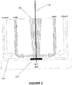
- LBI head 130 shapes the generated laser beam for application as a laser pulse 132 to the SUT 200, e.g., as shown in Figure 2 . More particularly, the LBI head 130 applies the laser pulse 132 to an ablative layer 210, e.g., an ablative tape (e.g., 3M 471 tape), black paint, etc., secured or otherwise applied to a surface of the SUT 200 to generate a compression wave in the SUT 200.
- An exemplary LBI head 130 generates a laser pulse 132 having a pulse duration of 100 - 300 ns, a pulse energy of 1 - 40 J, and a wavelength of 1054 nm.
- a longitudinal axis 134 of the laser pulse 132 generally aligns with a center of the ablative layer 210. It will be appreciated, however, that such is not required. Other implementations may instead ensure that the laser pulse 132 hits some portion of the ablative layer 210 such that the laser pulse 132 does not fall outside the ablative layer 210. In any event, characteristics of the SUT 200, e.g., strength, flaws, etc., are determined based on how the SUT 200 responds to the compression wave.
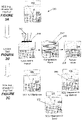
- Figures 3A-3B demonstrate the LBI process as applied to a SUT 200 comprising a first layer 220 bonded to a second layer 230.
- a non-destructive element 300 e.g., an ultrasound device, performs a Non-Destructive Evaluation (NDE) pre-test of the SUT 200.
- NDE 300 applies an ultra-sound wave to the SUT 200.
- the generated ultrasound wave passes through the SUT 200 and bounces off any boundaries, e.g., the boundary between the first layer 220 and the second layer 230.
- the NDE device 300 captures any reflected waves to generate an image of the SUT 200, including an image of the boundary.
- This NDE pre-test provides a baseline for the SUT 200 that serves as a basis for comparison once the structure test is complete.
- the LBI head 130 applies the generated laser pulse 132 to the ablative layer 210 to generate a compression wave 240 in the SUT 200.
- the laser pulse 132 generally damages the ablative layer such that only a portion 210' of the ablative layer 210 remains.
- the compression wave 240 passes through the first layer 220, through the boundary of the first and second layers, and through the second layer 230, ultimately causing a tension wave 250 to reflect off the far boundary of the second layer 230. While not shown, a portion of the compression wave amplitude may reflect off the boundary between the first layer 220 and the second layer 230, which reduces the amplitude of the compression wave in the second layer 230.
- Additional amplitude losses may occur due to scattering from interlaminar interfaces between plies, or defects (e.g., porosity in the first and/or second layers and/or in the adhesive layer used to bond the first and second layers).
- the amplitude of any losses depends on the properties of the materials used to fabricate the first and second layers, as well as acoustic properties of the adhesive bonding the first and second layers together.
- the NDE device 300 performs a NDE post-test ( Figure 3C ) to see if there is any change in the material relative to the NDE pre-test. For example, if the first and second layers 220, 230 as well as the bond between the first layer 220 and the second layer 230, are sufficiently strong (e.g., meet strength specifications) in the area of the test, then there are no flaws in the SUT 200, and the NDE post-test will match the NDE pre-test, e.g., as shown in Figure 3C1 .
- the tension wave 250 creates a flaw at the site of that weakness, which is detected by the NDE post-test, e.g., as shown in Figure 3C2 .
- the tension wave 250 creates a flaw 260 in the area of the weakness, which is detected by the NDE post-test, e.g., as shown in Figure 3C3.
- Figures 3C2 and 3C3 each only show a single weakness flaw 260 in specific areas of the SUT 200, it will be appreciated that the LBI test may expose multiple flaws in one or both layers 220, 230 and/or the bond area between the layers 220, 230.
- the LBI system 100 is designed to generate compression/tension waves with sufficient amplitude to create flaws in the SUT 200 wherever the SUT 200 has a weakness, but not with an amplitude that damages sufficiently strong (e.g., passes strength requirements) materials and/or bonds.
- the amplitude of the compression/tension wave is impacted by how much laser energy (e.g., due to power and size of the laser pulse 132) is incident on the ablative layer 210, the condition of the ablative layer 210, the type of overlay (e.g., water or otherwise), and/or the thickness of the overlay.
- the LBI system is calibrated to generate a pulse wave with the desired beam size and power that will achieve the desired compression wave (both in size and power).
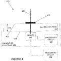
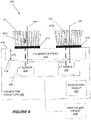
- FIG. 4 shows an exemplary block diagram of a calibration system 400 according to aspects of the solution presented herein.
- Calibration system 400 comprises a calibration panel 410, a sensor 420, and a processing circuit 430.
- the calibration panel 410 and sensor 420 are disposed in a calibration structure 450 to provide the desired alignment/spacing between the sensor 420 and the calibration panel 410.
- Figure 4 does not show the mounting hardware that mechanically secures the calibration panel 410, sensor 420, and calibration structure 450, but those skilled in the art will appreciate that the calibration system 400 includes such mounting hardware.
- the processing circuit 430 may be included in the same calibration structure 450 as the calibration panel 410 and sensor 420, or may be located remotely from the calibration structure 450. In either case, the processing circuit 430 connects to the sensor 420 via any suitable wires and/or connectors (not shown).
- the calibration panel 410 has a thickness 416 defined by generally parallel opposing surfaces 412, 414.
- Exemplary calibration panels 410 include, but are not limited to, a laminate panel, an aluminum panel (e.g., aluminum 6061), etc.
- the calibration panel 410 is made from aluminum that is 2 - 8 mm thick.
- the calibration panel 410 is rectangular with dimensions, e.g., 5" x 8", larger than the LBI head 130.
- the calibration panel 410 may comprise any known material and size having a known response to the desired laser pulse 132, e.g., the pulse intended for testing the SUT 200.
- One surface of the calibration panel 410 e.g., the first surface 412
- the first surface 412 is configured relative to the calibration structure 450 such that at least a portion of the first surface 412 is accessible, e.g., exposed to open air.
- the size of the accessible area of the calibration panel 410 is at least the size of the desired ablative layer 210, and thus is at least slightly larger than the laser pulse 132 generated by the LBI head 130. It will be appreciated that a larger area of the first surface 412, including the entire first surface 412, may be exposed to open air.
- the LBI head 130 is confined to the location of the ablative layer 210 and is coaxial with the sensor 420, where the LBI head 130 interfaces with the first surface 412 (or at least a portion of the first surface 412). While Figure 4 shows the first surface 412 as being aligned with one of the external boundaries of calibration structure 450, it will be appreciated that such is not required.
- Other implementations may have the calibration panel 410 mounted by the calibration structure 450 such that the first surface 412 extends outside/above an outer edge of the calibration structure 450, while still other implementations may have the calibration panel 410 mounted by the calibration structure 450 such that the first surface 412 is within/below an outer edge of the calibration structure 450. While not shown, the calibration panel may include alignment marks or structures (e.g., physical guides) useful for aligning the LBI head with the calibration panel 410 and sensor 420.
- the sensor 420 is fixedly spaced from the second surface 414 of the calibration panel 410.
- Sensor 420 may comprise any sensor capable of detecting surface motion of the second surface 414.
- sensor 420 is disposed in a housing fixedly mounted to the second surface 414. Whether mounted directly to the calibration panel 410 or mounted independently from the calibration panel 410, sensor 420 has a fixed spacing relative to the second surface 414 of the calibration panel 410 and a fixed alignment relative to the calibration panel 410, where the specific requirements of this spacing and alignment depend on the type of sensor used for sensor 420.
- the sensor 420 preferably has sufficient bandwidth to detect all desired characteristics of the compression wave, e.g., 1 - 200 MHz.
- Exemplary sensors may comprise non-contact sensors, which include but are not limited to, an Electro-Magnetic Acoustic Transducer (EMAT), a Velocity Interferometer System for any Reflector (VISAR), etc.
- EMAT Electro-Magnetic Acoustic Transducer
- VISAR Velocity Interferometer System for any Reflector
- Exemplary sensors 420 may also comprise contact sensors, e.g., a PolyVinyliDene Fluoride (PVDF) sensor, which directly contacts the second surface 414, an optical fiber, which may be embedded in the calibration panel 410, etc.
- PVDF PolyVinyliDene Fluoride
- sensors e.g., some contacted or embedded sensors
- the type of sensor used may directly impact the amplitude of the test compression wave that may be used for calibration.
- the processing circuit 430 processes the output of the sensor 420 to determine a calibration result responsive to one or more characteristics of the motion detected by the sensor 420.
- the processing circuit 430 processes the output of the sensor to determine the peak amplitude of the motion detected by the sensor 420.
- Other exemplary characteristics determined by the processing circuit 430 include, but are not limited to, frequency, amplitudes of one or more frequency components, and/or temporal characteristics, e.g., duration of the peak amplitude, duration of the compression wave, etc. From these one or more characteristics, the processing circuit 430 may determine a calibration result.
- the processing circuit 430 may further be configured to output the calibration result.
- the processing circuit 430 may simply output a pass/fail (e.g., green/red) indication.
- the processing circuit 430 may output additional calibration information, including but not limited to a relative calibration indication, e.g., 10% out of calibration.
- the processing circuit 430 may output an amplitude and a temporal width (e.g., pulse width) of a peak of the motion detected by the sensor 420.
- the processing circuit 430 may also or alternatively compare the amplitude and pulse width to a calibration amplitude and pulse width to determine whether the detected amplitude and pulse width is within an acceptable calibration range, e.g., 10%, of the calibration amplitude and pulse width. If within the calibration range, the processing circuit 430 may output the actual percentage in addition to the pass/fail indication.
- FIGs 5-7 show exemplary aspects of a calibration process as implemented by the calibration system 400.
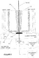
- Figure 5 shows an exemplary calibration system 400 relative to the LBI head 130
- Figure 6 shows an exemplary calibration method 500
- Figure 7 shows an exemplary calibration process from the perspective of the system alignment and the involved components.
- LBI head 130 applies the laser pulse 132 to the ablative layer 210, which generates a compression wave 240 in the calibration panel 410 (block 510).
- the impact of the laser pulse 132 damages the ablative layer 210, resulting in a marked ablative layer 210', which may show the footprint of the beam.
- the sensor 420 senses the movement 255 of the second surface caused by the compression wave 240, where a longitudinal axis 422 of the sensor 420 generally aligns with a longitudinal axis 134 of the LBI head 130 within a tolerance window defined by the beam diameter (block 520).
- the processing circuit 430 outputs a calibration result for the LBI system 100 responsive to one or more characteristics of the sensed compression wave (block 530). Once the calibration is complete, the calibration method ends (block 550).
- the calibration process disclosed herein relies on detection and evaluation of the compression wave generated by the impact of the laser pulse 132, as opposed to analyzing the spot generated by the beam, the calibration results may be acquired significantly faster, e.g., within seconds of the application of the laser pulse 132, than with conventional techniques. Even when the time required to align the calibration system 400 with the LBI head 130 is taken into consideration, the complete calibration process may be achieved in minutes. For example, experimental implementations of the calibration system 400 set up in the lab, which involves significant manual movement and/or manipulation of the data, have provided calibration results in a few minutes. Integrated systems, which will automate most, if not all, of the manual aspects, are expected to provide a calibration result in 15 seconds or less after application of the laser pulse 132.
- an integrated calibration system may execute the test, perform the comparison between the detected amplitude and pulse width and the calibration amplitude and pulse width, and output the associated result 15 seconds or less after the application of the laser pulse 132.
- blocks 510-530 of the calibration method 500 may be repeated (block 540) whenever and as often as desired. For example, if the calibration results indicate the LBI system 100 is out of calibration, blocks 510-530 of the calibration method 500 may be repeated to confirm the calibration results and/or after adjustment of the LBI system 100 to determine if the adjustment brought the LBI system 100 into calibration.
- blocks 510-530 of the calibration method 500 may be repeated at any desired time and/or interval, e.g., at the beginning of a shift, at the end of a shift, after running some number of tests (e.g., after 500 - 1000 tests), after changing the type of SUT 200 being tested, etc.
- the efficiency of the sensor 420 depends on the location of the sensor relative to the laser pulse 132 as well as relative to the calibration panel 410. Thus, not only is the angular orientation relative to the calibration panel 410 and/or the spacing from the second surface 414 important, but the alignment of the longitudinal axis 422 of the sensor 420 relative to the laser pulse 132 is also important.
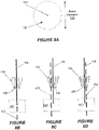
- Figure 8A shows an exemplary laser pulse 132 having a longitudinal axis 134 and a beam diameter 136, e.g., at least 8 mm.
- the longitudinal axis 422 of the sensor 420 should be within the beam diameter 136 of the laser pulse 132, and preferably within 2 - 3 mm of the longitudinal axis 134 of the LBI head 130.
- sensor 420 comprises a VISAR
- the calibration panel 410 may include alignment marks or structures, which help an operator align the LBI head 130 relative to the sensor 420 for the calibration process.
- sensor 420 comprising a single sensor having a longitudinal axis 422 generally aligned with the LBI head 130 within the beam diameter 136.
- the solution is not limited to a single sensor, however.
- Figure 9 shows exemplary aspects where sensor 420 comprises a first sensor 424 and a second sensor 426, where each sensor is associated with a corresponding LBI head 130.
- the first sensor 424 may comprise a VISAR and the second sensor 426 may comprise an EMAT.
- the longitudinal axis 4221 of the first sensor 424 and the longitudinal axis 4222 of the second sensor 426 each generally align with the longitudinal axis 134 of a corresponding the LBI head 130 within the beam diameter 136, as shown in Figure 9 .
- Figure 9 shows the first sensor 424 and the second sensor 426 having the same spacing from the second surface 414 of the calibration panel 410, such equal spacing is not required.
- Other aspects may include more than two sensors. In so doing, aspects of the solution presented herein enable different types of data regarding the compression wave to be collected, e.g., due to the capabilities of the different sensors.
- the compression wave 240 used to test the strength of a SUT 200 may be generated using any means for generating a shockwave (which generates the compression wave in the SUT 200), and thus the calibration solution presented herein applies to any means for generating a compression wave 240 used for such strength tests.
- Exemplary non-LBI means for generating such shockwaves include, but are not limited to, a flyer "gun" that propels an object onto the first surface 412 of the calibration panel, an exploding bridge wire, etc.
Landscapes
- Physics & Mathematics (AREA)
- Biochemistry (AREA)
- General Physics & Mathematics (AREA)
- Life Sciences & Earth Sciences (AREA)
- Chemical & Material Sciences (AREA)
- Analytical Chemistry (AREA)
- Pathology (AREA)
- General Health & Medical Sciences (AREA)
- Health & Medical Sciences (AREA)
- Immunology (AREA)
- Acoustics & Sound (AREA)
- Optics & Photonics (AREA)
- Electromagnetism (AREA)
- Investigating Or Analyzing Materials By The Use Of Ultrasonic Waves (AREA)
- Length Measuring Devices By Optical Means (AREA)
Claims (15)
- Procédé (500) de détermination d'un résultat d'étalonnage pour un système de contrôle laser (100) comprenant une tête de contrôle d'assemblages par laser (130) configurée pour appliquer une impulsion laser (132) à une surface d'une structure d'essai (200) pour identifier une résistance de la structure d'essai (200), le procédé (500) comprenant :la génération (510) d'une onde de compression (240) dans un panneau d'étalonnage (410) en réponse à une impulsion laser (132) avec un diamètre de faisceau (136) appliquée par la tête de contrôle d'assemblages par laser (130) à une couche ablative (210) fixée à une première surface (412) du panneau d'étalonnage (410), le panneau d'étalonnage (410) comprenant la première surface (412) espacée d'une deuxième surface (414) par une épaisseur prédéterminée (416), ladite première surface (412) étant généralement parallèle à ladite deuxième surface (414) ;la détection (520) de l'onde de compression (240) au moyen d'un capteur de mouvement de surface (420) espacé de façon fixe de la deuxième surface (414) du panneau d'étalonnage (410) par une distance prédéterminée, un axe longitudinal (422) du capteur de mouvement de surface (420) s'alignant généralement avec un axe longitudinal (134) de la tête de contrôle d'assemblages par laser (130) à l'intérieur d'une fenêtre de tolérance définie par le diamètre de faisceau (136) ; etla délivrance (530) d'un résultat d'étalonnage pour le système de contrôle laser (100) en réponse à une ou plusieurs caractéristiques de l'onde de compression détectée.
- Procédé (500) de la revendication 1 dans lequel le capteur de mouvement de surface (420) comprend un transducteur acoustique électromagnétique (EMAT).
- Procédé (500) de la revendication 2 dans lequel ladite délivrance (530) du résultat d'étalonnage du système de contrôle laser (100) comprend :la détection d'au moins une amplitude de l'onde de compression détectée ; etla délivrance du résultat d'étalonnage déterminé en réponse à l'au moins une amplitude détectée.
- Procédé (500) de l'une quelconque des revendications 1 à 3 dans lequel le capteur de mouvement de surface (420) comprend un système d'interféromètre de vitesse pour tout réflecteur (VISAR) ayant une inclinaison fixe par rapport au panneau d'étalonnage (410).
- Procédé (500) de la revendication 4 dans lequel ladite délivrance (530) du résultat d'étalonnage du système de contrôle laser (100) comprend :la détermination d'une amplitude de l'onde de compression en réponse à la caractéristique ou aux caractéristiques de l'onde de compression détectée ; etla délivrance du résultat d'étalonnage en réponse à l'amplitude déterminée.
- Procédé (500) de l'une quelconque des revendications 1 à 5 dans lequel ladite délivrance (530) du résultat d'étalonnage comprend la délivrance du résultat d'étalonnage moins d'une minute après que la tête de contrôle d'assemblages par laser (130) a appliqué l'impulsion laser (132) à la couche ablative (210) fixée au panneau d'étalonnage (410).
- Procédé (500) de l'une quelconque des revendications 1 à 6 comprenant en outre, si le résultat d'étalonnage indique que le système de contrôle laser est hors étalonnage, la répétition (540) de l'étalonnage par :génération, après qu'un ou plusieurs réglages ont été effectués sur le système de contrôle laser (100), d'une deuxième onde de compression (240) dans le panneau d'étalonnage (410) en réponse à une deuxième impulsion laser (132) avec le diamètre de faisceau (136) appliquée par la tête de contrôle d'assemblages par laser (130) à une nouvelle couche ablative (210) fixée à la première surface (412) du panneau d'étalonnage (410) ;détection de la deuxième onde de compression (240) au moyen du capteur de mouvement de surface (420) ; etdélivrance d'un deuxième résultat d'étalonnage pour le système de contrôle laser (100) en réponse à une ou plusieurs caractéristiques de la deuxième onde de compression détectée.
- Procédé (500) de la revendication 7 dans lequel le résultat d'étalonnage comprend un premier résultat d'étalonnage, et dans lequel ladite délivrance du deuxième résultat d'étalonnage comprend la délivrance du deuxième résultat d'étalonnage moins d'une minute après la génération de la deuxième onde de compression.
- Procédé (500) de l'une quelconque des revendications 1 à 8 dans lequel le résultat d'étalonnage comprend un premier résultat d'étalonnage, le procédé comprenant en outre la répétition (540) de l'étalonnage par :génération d'une deuxième onde de compression (240) dans le panneau d'étalonnage (410) en réponse à une deuxième impulsion laser (132) avec le diamètre de faisceau (136) appliquée par la tête de contrôle d'assemblages par laser (130) à une nouvelle couche ablative (210) fixée à la première surface (412) du panneau d'étalonnage (410) ;détection de la deuxième onde de compression (240) au moyen du capteur de mouvement de surface (420) ; etdélivrance d'un deuxième résultat d'étalonnage pour le système de contrôle laser (100) en réponse à une ou plusieurs caractéristiques de la deuxième onde de compression détectée.
- Procédé (500) de la revendication 9 dans lequel le premier résultat d'étalonnage est obtenu à un premier moment avant que le système de contrôle laser (100) évalue une ou plusieurs structures d'essai (200), et le deuxième résultat d'étalonnage est obtenu à un deuxième moment après que le système de contrôle laser (100) a évalué la ou les structures d'essai (200).
- Procédé (500) de la revendication 9 ou 10 dans lequel le premier résultat d'étalonnage est obtenu à un premier moment avant que le système de contrôle laser (100) évalue un premier ensemble d'une ou plusieurs structures d'essai (200), et le deuxième résultat d'étalonnage est obtenu à un deuxième moment avant que le système de contrôle laser (100) évalue un deuxième ensemble d'une ou plusieurs structures d'essai (200), ledit deuxième moment survenant après ledit premier moment.
- Système d'étalonnage destiné à déterminer un résultat d'étalonnage pour un système de contrôle laser (100) comprenant :une tête de contrôle d'assemblages par laser (130) configurée pour appliquer une impulsion laser (132) à une structure d'essai (200) pour identifier une résistance de la structure d'essai (200) ;un panneau d'étalonnage (410) ;un capteur de mouvement de surface (420) ; etun circuit de traitement (430) ;dans lequel le panneau d'étalonnage (410) comprend une première surface (412) généralement parallèle à une deuxième surface (414) et espacée de la deuxième surface (414) par une épaisseur prédéterminée (416), le capteur de mouvement de surface (420) étant espacé de façon fixe de la deuxième surface (414) du panneau d'étalonnage (410) par une distance prédéterminée, etle système d'étalonnage comprenant une couche ablative (210) fixée à la première surface (412) du panneau d'étalonnage (410) ;dans lequel le capteur de mouvement de surface (420) est configuré pour détecter une onde de compression générée dans le panneau d'étalonnage (410) en réponse à une impulsion laser avec un diamètre de faisceau appliquée par la tête de contrôle d'assemblages par laser (130) à la couche ablative (210) fixée à la première surface (412) du panneau d'étalonnage (410), un axe longitudinal (422) du capteur de mouvement de surface (420) étant généralement aligné avec un axe longitudinal (134) de la tête de contrôle d'assemblages par laser (132) à l'intérieur d'une fenêtre de tolérance définie par le diamètre de faisceau ; etdans lequel le circuit de traitement (430) est configuré pour délivrer un résultat d'étalonnage pour le système de contrôle laser (100) en réponse à une ou plusieurs caractéristiques de l'onde de compression détectée.
- Système d'étalonnage de la revendication 12, dans lequel le capteur de mouvement de surface comprend un transducteur acoustique électromagnétique, EMAT.
- Système d'étalonnage de la revendication 12, dans lequel le capteur de mouvement de surface comprend un système d'interféromètre de vitesse pour tout réflecteur, VISAR, ayant une inclinaison fixe par rapport au panneau d'étalonnage.
- Système d'étalonnage de la revendication 12, dans lequel le capteur de mouvement de surface comprend un premier capteur de mouvement de surface espacé de façon fixe de la deuxième surface du panneau d'étalonnage par une première distance prédéterminée, et un deuxième capteur de mouvement de surface proche du premier capteur de mouvement de surface et espacé de façon fixe de la deuxième surface du panneau d'étalonnage par une deuxième distance prédéterminée.
Applications Claiming Priority (1)
| Application Number | Priority Date | Filing Date | Title |
|---|---|---|---|
| US16/245,632 US11143629B2 (en) | 2019-01-11 | 2019-01-11 | Laser bond inspection calibration system |
Publications (2)
| Publication Number | Publication Date |
|---|---|
| EP3680652A1 EP3680652A1 (fr) | 2020-07-15 |
| EP3680652B1 true EP3680652B1 (fr) | 2023-01-11 |
Family
ID=67928627
Family Applications (1)
| Application Number | Title | Priority Date | Filing Date |
|---|---|---|---|
| EP19196534.2A Active EP3680652B1 (fr) | 2019-01-11 | 2019-09-10 | Système d'étalonnage d'inspection de liaison au laser |
Country Status (3)
| Country | Link |
|---|---|
| US (1) | US11143629B2 (fr) |
| EP (1) | EP3680652B1 (fr) |
| JP (1) | JP7332397B2 (fr) |
Families Citing this family (1)
| Publication number | Priority date | Publication date | Assignee | Title |
|---|---|---|---|---|
| US20250341492A1 (en) * | 2024-05-03 | 2025-11-06 | The Boeing Company | Testing a Bond Between Two Components |
Family Cites Families (15)
| Publication number | Priority date | Publication date | Assignee | Title |
|---|---|---|---|---|
| US6848321B2 (en) * | 2001-10-17 | 2005-02-01 | The Boeing Company | Bond strength measurement system using shock loads |
| US7770454B2 (en) * | 2003-09-26 | 2010-08-10 | Lsp Technologies, Inc. | Laser system and method for non-destructive bond detection and evaluation |
| US8156811B2 (en) * | 2004-09-15 | 2012-04-17 | Lsp Technologies, Inc. | Apparatus and method for non-destructive testing |
| US7681453B2 (en) * | 2005-03-29 | 2010-03-23 | Lockheed Martin Corporation | System and method to calibrate multiple sensors |
| CN106018563A (zh) * | 2007-02-21 | 2016-10-12 | 洛克希德马丁公司 | 用于激光超声波探伤的关节型机器人 |
| WO2009073979A1 (fr) * | 2007-12-12 | 2009-06-18 | Carson Jeffrey J L | Imageur photo-acoustique tridimensionnel et procédés de calibrage d'un imageur |
| JP2013057521A (ja) * | 2011-09-07 | 2013-03-28 | Suzuki Motor Corp | 超音波発生方法および非破壊検査方法 |
| US9857288B2 (en) | 2013-11-01 | 2018-01-02 | Lsp Technologies, Inc. | Laser bond inspection with compact surface motion sensor |
| US20150128717A1 (en) * | 2013-11-13 | 2015-05-14 | Gary J. May | Automated dynamic laser bond inspection system |
| US10048230B2 (en) | 2013-11-14 | 2018-08-14 | The Boeing Company | Structural bond inspection |
| JP2015230171A (ja) * | 2014-06-03 | 2015-12-21 | 株式会社東芝 | 避雷素子及びそれを覆う碍管からなる避雷器における避雷素子の温度測定方法 |
| US9464965B2 (en) | 2014-11-07 | 2016-10-11 | The Boeing Company | Method for creating non-inserted artificial disbonds or delaminations for nondestructive inspection test standards |
| US9995670B2 (en) * | 2015-12-09 | 2018-06-12 | The Boeing Company | Method of controlling a laser bond inspection system |
| US10724997B2 (en) * | 2018-04-30 | 2020-07-28 | The Boeing Company | System combining laser ablation with ultrasound inspection of parts |
| US10753909B2 (en) * | 2018-08-13 | 2020-08-25 | The Boeing Company | Laser for laser bond inspection system and laser ultrasonic inspection system |
-
2019
- 2019-01-11 US US16/245,632 patent/US11143629B2/en active Active
- 2019-09-04 JP JP2019161277A patent/JP7332397B2/ja active Active
- 2019-09-10 EP EP19196534.2A patent/EP3680652B1/fr active Active
Also Published As
| Publication number | Publication date |
|---|---|
| US20200225195A1 (en) | 2020-07-16 |
| JP2020112538A (ja) | 2020-07-27 |
| JP7332397B2 (ja) | 2023-08-23 |
| EP3680652A1 (fr) | 2020-07-15 |
| US11143629B2 (en) | 2021-10-12 |
Similar Documents
| Publication | Publication Date | Title |
|---|---|---|
| US10048230B2 (en) | Structural bond inspection | |
| Zhao et al. | Active health monitoring of an aircraft wing with embedded piezoelectric sensor/actuator network: I. Defect detection, localization and growth monitoring | |
| Ihn et al. | Pitch-catch active sensing methods in structural health monitoring for aircraft structures | |
| EP3070467B1 (fr) | Système d'essai par ultrasons, procédé d'essai par ultrasons et procédé de fabrication de pièce d'aéronef | |
| JPS61283864A (ja) | 金属媒体の欠陥の超音波測定方法 | |
| Michaels | Ultrasonic wavefield imaging: Research tool or emerging NDE method? | |
| CN115791596B (zh) | 一种基于3d激光测振的界面损伤综合测试系统及方法 | |
| Du et al. | Damage imaging in composite laminates using broadband multipath lamb waves | |
| Jurek et al. | Non-contact excitation and focusing of guided waves in CFRP composite plate by air-coupled transducers for application in damage detection | |
| CN105424798A (zh) | 一种主动检测金属薄壁结构件中缺陷的方法 | |
| EP3680652B1 (fr) | Système d'étalonnage d'inspection de liaison au laser | |
| KR20200011835A (ko) | 배열형 초음파 센서를 이용한 펄스 에코형 비선형 검사 장치 | |
| Cuc et al. | Disbond detection in adhesively bonded structures using piezoelectric wafer active sensors | |
| Giurgiutiu et al. | Embedded ultrasonics NDE with piezoelectric wafer active sensors | |
| Hosoya et al. | Lamb waves evaluation in CFRP plates with laser shock wave technique | |
| WO2017050452A1 (fr) | Procédé et système permettant d'inspecter des structures en forme de plaque par ultrasons | |
| KR101191364B1 (ko) | 비선형 평가 시스템 및 장치 | |
| Rathod et al. | Lamb wave based monitoring of plate-stiffener deboding using a circular array of piezoelectric sensors | |
| JPS591980B2 (ja) | 超音波検査装置 | |
| Mueller et al. | Effects of debonding of PWAS on the wave propagation and the electro-mechanical impedance spectrum | |
| CN113777047A (zh) | 基于热弹效应的金属表面裂纹位置及大小的识别方法 | |
| Djordjevic | Quantitative ultrasonic guided wave testing of composites | |
| Basu et al. | Guided Wave Resonance to Identify Damage in Thin Composite Plates | |
| Pfeiffer et al. | Identification of impact damage in sandwich composites by acoustic camera detection of leaky Lamb wave mode conversions | |
| Jurek et al. | Non-contact guided wave excitation in composite plate by the ultrasound transmitter |
Legal Events
| Date | Code | Title | Description |
|---|---|---|---|
| PUAI | Public reference made under article 153(3) epc to a published international application that has entered the european phase |
Free format text: ORIGINAL CODE: 0009012 |
|
| STAA | Information on the status of an ep patent application or granted ep patent |
Free format text: STATUS: THE APPLICATION HAS BEEN PUBLISHED |
|
| AK | Designated contracting states |
Kind code of ref document: A1 Designated state(s): AL AT BE BG CH CY CZ DE DK EE ES FI FR GB GR HR HU IE IS IT LI LT LU LV MC MK MT NL NO PL PT RO RS SE SI SK SM TR |
|
| AX | Request for extension of the european patent |
Extension state: BA ME |
|
| STAA | Information on the status of an ep patent application or granted ep patent |
Free format text: STATUS: REQUEST FOR EXAMINATION WAS MADE |
|
| 17P | Request for examination filed |
Effective date: 20201123 |
|
| RBV | Designated contracting states (corrected) |
Designated state(s): AL AT BE BG CH CY CZ DE DK EE ES FI FR GB GR HR HU IE IS IT LI LT LU LV MC MK MT NL NO PL PT RO RS SE SI SK SM TR |
|
| GRAP | Despatch of communication of intention to grant a patent |
Free format text: ORIGINAL CODE: EPIDOSNIGR1 |
|
| STAA | Information on the status of an ep patent application or granted ep patent |
Free format text: STATUS: GRANT OF PATENT IS INTENDED |
|
| INTG | Intention to grant announced |
Effective date: 20220422 |
|
| GRAJ | Information related to disapproval of communication of intention to grant by the applicant or resumption of examination proceedings by the epo deleted |
Free format text: ORIGINAL CODE: EPIDOSDIGR1 |
|
| STAA | Information on the status of an ep patent application or granted ep patent |
Free format text: STATUS: REQUEST FOR EXAMINATION WAS MADE |
|
| GRAP | Despatch of communication of intention to grant a patent |
Free format text: ORIGINAL CODE: EPIDOSNIGR1 |
|
| STAA | Information on the status of an ep patent application or granted ep patent |
Free format text: STATUS: GRANT OF PATENT IS INTENDED |
|
| INTC | Intention to grant announced (deleted) | ||
| INTG | Intention to grant announced |
Effective date: 20220726 |
|
| GRAS | Grant fee paid |
Free format text: ORIGINAL CODE: EPIDOSNIGR3 |
|
| GRAA | (expected) grant |
Free format text: ORIGINAL CODE: 0009210 |
|
| STAA | Information on the status of an ep patent application or granted ep patent |
Free format text: STATUS: THE PATENT HAS BEEN GRANTED |
|
| AK | Designated contracting states |
Kind code of ref document: B1 Designated state(s): AL AT BE BG CH CY CZ DE DK EE ES FI FR GB GR HR HU IE IS IT LI LT LU LV MC MK MT NL NO PL PT RO RS SE SI SK SM TR |
|
| REG | Reference to a national code |
Ref country code: GB Ref legal event code: FG4D |
|
| REG | Reference to a national code |
Ref country code: CH Ref legal event code: EP |
|
| REG | Reference to a national code |
Ref country code: DE Ref legal event code: R096 Ref document number: 602019024223 Country of ref document: DE |
|
| REG | Reference to a national code |
Ref country code: IE Ref legal event code: FG4D |
|
| REG | Reference to a national code |
Ref country code: AT Ref legal event code: REF Ref document number: 1543714 Country of ref document: AT Kind code of ref document: T Effective date: 20230215 |
|
| RAP4 | Party data changed (patent owner data changed or rights of a patent transferred) |
Owner name: THE BOEING COMPANY |
|
| REG | Reference to a national code |
Ref country code: LT Ref legal event code: MG9D |
|
| REG | Reference to a national code |
Ref country code: NL Ref legal event code: MP Effective date: 20230111 |
|
| REG | Reference to a national code |
Ref country code: AT Ref legal event code: MK05 Ref document number: 1543714 Country of ref document: AT Kind code of ref document: T Effective date: 20230111 |
|
| P01 | Opt-out of the competence of the unified patent court (upc) registered |
Effective date: 20230516 |
|
| PG25 | Lapsed in a contracting state [announced via postgrant information from national office to epo] |
Ref country code: NL Free format text: LAPSE BECAUSE OF FAILURE TO SUBMIT A TRANSLATION OF THE DESCRIPTION OR TO PAY THE FEE WITHIN THE PRESCRIBED TIME-LIMIT Effective date: 20230111 |
|
| PG25 | Lapsed in a contracting state [announced via postgrant information from national office to epo] |
Ref country code: RS Free format text: LAPSE BECAUSE OF FAILURE TO SUBMIT A TRANSLATION OF THE DESCRIPTION OR TO PAY THE FEE WITHIN THE PRESCRIBED TIME-LIMIT Effective date: 20230111 Ref country code: PT Free format text: LAPSE BECAUSE OF FAILURE TO SUBMIT A TRANSLATION OF THE DESCRIPTION OR TO PAY THE FEE WITHIN THE PRESCRIBED TIME-LIMIT Effective date: 20230511 Ref country code: NO Free format text: LAPSE BECAUSE OF FAILURE TO SUBMIT A TRANSLATION OF THE DESCRIPTION OR TO PAY THE FEE WITHIN THE PRESCRIBED TIME-LIMIT Effective date: 20230411 Ref country code: LV Free format text: LAPSE BECAUSE OF FAILURE TO SUBMIT A TRANSLATION OF THE DESCRIPTION OR TO PAY THE FEE WITHIN THE PRESCRIBED TIME-LIMIT Effective date: 20230111 Ref country code: LT Free format text: LAPSE BECAUSE OF FAILURE TO SUBMIT A TRANSLATION OF THE DESCRIPTION OR TO PAY THE FEE WITHIN THE PRESCRIBED TIME-LIMIT Effective date: 20230111 Ref country code: HR Free format text: LAPSE BECAUSE OF FAILURE TO SUBMIT A TRANSLATION OF THE DESCRIPTION OR TO PAY THE FEE WITHIN THE PRESCRIBED TIME-LIMIT Effective date: 20230111 Ref country code: ES Free format text: LAPSE BECAUSE OF FAILURE TO SUBMIT A TRANSLATION OF THE DESCRIPTION OR TO PAY THE FEE WITHIN THE PRESCRIBED TIME-LIMIT Effective date: 20230111 Ref country code: AT Free format text: LAPSE BECAUSE OF FAILURE TO SUBMIT A TRANSLATION OF THE DESCRIPTION OR TO PAY THE FEE WITHIN THE PRESCRIBED TIME-LIMIT Effective date: 20230111 |
|
| PG25 | Lapsed in a contracting state [announced via postgrant information from national office to epo] |
Ref country code: SE Free format text: LAPSE BECAUSE OF FAILURE TO SUBMIT A TRANSLATION OF THE DESCRIPTION OR TO PAY THE FEE WITHIN THE PRESCRIBED TIME-LIMIT Effective date: 20230111 Ref country code: PL Free format text: LAPSE BECAUSE OF FAILURE TO SUBMIT A TRANSLATION OF THE DESCRIPTION OR TO PAY THE FEE WITHIN THE PRESCRIBED TIME-LIMIT Effective date: 20230111 Ref country code: IS Free format text: LAPSE BECAUSE OF FAILURE TO SUBMIT A TRANSLATION OF THE DESCRIPTION OR TO PAY THE FEE WITHIN THE PRESCRIBED TIME-LIMIT Effective date: 20230511 Ref country code: GR Free format text: LAPSE BECAUSE OF FAILURE TO SUBMIT A TRANSLATION OF THE DESCRIPTION OR TO PAY THE FEE WITHIN THE PRESCRIBED TIME-LIMIT Effective date: 20230412 Ref country code: FI Free format text: LAPSE BECAUSE OF FAILURE TO SUBMIT A TRANSLATION OF THE DESCRIPTION OR TO PAY THE FEE WITHIN THE PRESCRIBED TIME-LIMIT Effective date: 20230111 |
|
| REG | Reference to a national code |
Ref country code: DE Ref legal event code: R097 Ref document number: 602019024223 Country of ref document: DE |
|
| PG25 | Lapsed in a contracting state [announced via postgrant information from national office to epo] |
Ref country code: SM Free format text: LAPSE BECAUSE OF FAILURE TO SUBMIT A TRANSLATION OF THE DESCRIPTION OR TO PAY THE FEE WITHIN THE PRESCRIBED TIME-LIMIT Effective date: 20230111 Ref country code: RO Free format text: LAPSE BECAUSE OF FAILURE TO SUBMIT A TRANSLATION OF THE DESCRIPTION OR TO PAY THE FEE WITHIN THE PRESCRIBED TIME-LIMIT Effective date: 20230111 Ref country code: EE Free format text: LAPSE BECAUSE OF FAILURE TO SUBMIT A TRANSLATION OF THE DESCRIPTION OR TO PAY THE FEE WITHIN THE PRESCRIBED TIME-LIMIT Effective date: 20230111 Ref country code: DK Free format text: LAPSE BECAUSE OF FAILURE TO SUBMIT A TRANSLATION OF THE DESCRIPTION OR TO PAY THE FEE WITHIN THE PRESCRIBED TIME-LIMIT Effective date: 20230111 Ref country code: CZ Free format text: LAPSE BECAUSE OF FAILURE TO SUBMIT A TRANSLATION OF THE DESCRIPTION OR TO PAY THE FEE WITHIN THE PRESCRIBED TIME-LIMIT Effective date: 20230111 |
|
| PLBE | No opposition filed within time limit |
Free format text: ORIGINAL CODE: 0009261 |
|
| STAA | Information on the status of an ep patent application or granted ep patent |
Free format text: STATUS: NO OPPOSITION FILED WITHIN TIME LIMIT |
|
| PG25 | Lapsed in a contracting state [announced via postgrant information from national office to epo] |
Ref country code: SK Free format text: LAPSE BECAUSE OF FAILURE TO SUBMIT A TRANSLATION OF THE DESCRIPTION OR TO PAY THE FEE WITHIN THE PRESCRIBED TIME-LIMIT Effective date: 20230111 |
|
| 26N | No opposition filed |
Effective date: 20231012 |
|
| PG25 | Lapsed in a contracting state [announced via postgrant information from national office to epo] |
Ref country code: SI Free format text: LAPSE BECAUSE OF FAILURE TO SUBMIT A TRANSLATION OF THE DESCRIPTION OR TO PAY THE FEE WITHIN THE PRESCRIBED TIME-LIMIT Effective date: 20230111 |
|
| REG | Reference to a national code |
Ref country code: CH Ref legal event code: PL |
|
| PG25 | Lapsed in a contracting state [announced via postgrant information from national office to epo] |
Ref country code: LU Free format text: LAPSE BECAUSE OF NON-PAYMENT OF DUE FEES Effective date: 20230910 |
|
| REG | Reference to a national code |
Ref country code: BE Ref legal event code: MM Effective date: 20230930 |
|
| PG25 | Lapsed in a contracting state [announced via postgrant information from national office to epo] |
Ref country code: LU Free format text: LAPSE BECAUSE OF NON-PAYMENT OF DUE FEES Effective date: 20230910 Ref country code: IT Free format text: LAPSE BECAUSE OF FAILURE TO SUBMIT A TRANSLATION OF THE DESCRIPTION OR TO PAY THE FEE WITHIN THE PRESCRIBED TIME-LIMIT Effective date: 20230111 Ref country code: MC Free format text: LAPSE BECAUSE OF FAILURE TO SUBMIT A TRANSLATION OF THE DESCRIPTION OR TO PAY THE FEE WITHIN THE PRESCRIBED TIME-LIMIT Effective date: 20230111 |
|
| REG | Reference to a national code |
Ref country code: IE Ref legal event code: MM4A |
|
| PG25 | Lapsed in a contracting state [announced via postgrant information from national office to epo] |
Ref country code: IE Free format text: LAPSE BECAUSE OF NON-PAYMENT OF DUE FEES Effective date: 20230910 |
|
| PG25 | Lapsed in a contracting state [announced via postgrant information from national office to epo] |
Ref country code: CH Free format text: LAPSE BECAUSE OF NON-PAYMENT OF DUE FEES Effective date: 20230930 |
|
| PG25 | Lapsed in a contracting state [announced via postgrant information from national office to epo] |
Ref country code: IE Free format text: LAPSE BECAUSE OF NON-PAYMENT OF DUE FEES Effective date: 20230910 Ref country code: CH Free format text: LAPSE BECAUSE OF NON-PAYMENT OF DUE FEES Effective date: 20230930 |
|
| PG25 | Lapsed in a contracting state [announced via postgrant information from national office to epo] |
Ref country code: BE Free format text: LAPSE BECAUSE OF NON-PAYMENT OF DUE FEES Effective date: 20230930 |
|
| PG25 | Lapsed in a contracting state [announced via postgrant information from national office to epo] |
Ref country code: BG Free format text: LAPSE BECAUSE OF FAILURE TO SUBMIT A TRANSLATION OF THE DESCRIPTION OR TO PAY THE FEE WITHIN THE PRESCRIBED TIME-LIMIT Effective date: 20230111 |
|
| PG25 | Lapsed in a contracting state [announced via postgrant information from national office to epo] |
Ref country code: BG Free format text: LAPSE BECAUSE OF FAILURE TO SUBMIT A TRANSLATION OF THE DESCRIPTION OR TO PAY THE FEE WITHIN THE PRESCRIBED TIME-LIMIT Effective date: 20230111 |
|
| PG25 | Lapsed in a contracting state [announced via postgrant information from national office to epo] |
Ref country code: CY Free format text: LAPSE BECAUSE OF FAILURE TO SUBMIT A TRANSLATION OF THE DESCRIPTION OR TO PAY THE FEE WITHIN THE PRESCRIBED TIME-LIMIT; INVALID AB INITIO Effective date: 20190910 |
|
| PG25 | Lapsed in a contracting state [announced via postgrant information from national office to epo] |
Ref country code: HU Free format text: LAPSE BECAUSE OF FAILURE TO SUBMIT A TRANSLATION OF THE DESCRIPTION OR TO PAY THE FEE WITHIN THE PRESCRIBED TIME-LIMIT; INVALID AB INITIO Effective date: 20190910 |
|
| PGFP | Annual fee paid to national office [announced via postgrant information from national office to epo] |
Ref country code: DE Payment date: 20250929 Year of fee payment: 7 |
|
| PGFP | Annual fee paid to national office [announced via postgrant information from national office to epo] |
Ref country code: GB Payment date: 20250929 Year of fee payment: 7 |
|
| PGFP | Annual fee paid to national office [announced via postgrant information from national office to epo] |
Ref country code: FR Payment date: 20250925 Year of fee payment: 7 |
|
| PG25 | Lapsed in a contracting state [announced via postgrant information from national office to epo] |
Ref country code: TR Free format text: LAPSE BECAUSE OF FAILURE TO SUBMIT A TRANSLATION OF THE DESCRIPTION OR TO PAY THE FEE WITHIN THE PRESCRIBED TIME-LIMIT Effective date: 20230111 |