EP3680680A1 - Verfahren zum erhalt eines optimierten betriebsparameters, speichermedium und magnetresonanzgerät - Google Patents
Verfahren zum erhalt eines optimierten betriebsparameters, speichermedium und magnetresonanzgerät Download PDFInfo
- Publication number
- EP3680680A1 EP3680680A1 EP19151327.4A EP19151327A EP3680680A1 EP 3680680 A1 EP3680680 A1 EP 3680680A1 EP 19151327 A EP19151327 A EP 19151327A EP 3680680 A1 EP3680680 A1 EP 3680680A1
- Authority
- EP
- European Patent Office
- Prior art keywords
- gradient
- echo
- echo signals
- readout
- parameters
- Prior art date
- Legal status (The legal status is an assumption and is not a legal conclusion. Google has not performed a legal analysis and makes no representation as to the accuracy of the status listed.)
- Withdrawn
Links
- 238000000034 method Methods 0.000 title claims abstract description 33
- 230000005284 excitation Effects 0.000 claims abstract description 20
- 230000003247 decreasing effect Effects 0.000 claims description 5
- 238000013500 data storage Methods 0.000 claims description 4
- 238000005259 measurement Methods 0.000 description 18
- 238000002592 echocardiography Methods 0.000 description 9
- 238000009792 diffusion process Methods 0.000 description 7
- 238000003384 imaging method Methods 0.000 description 6
- 238000010586 diagram Methods 0.000 description 4
- 238000003708 edge detection Methods 0.000 description 3
- 238000002360 preparation method Methods 0.000 description 3
- 238000004458 analytical method Methods 0.000 description 2
- VQKWAUROYFTROF-UHFFFAOYSA-N arc-31 Chemical compound O=C1N(CCN(C)C)C2=C3C=C4OCOC4=CC3=NN=C2C2=C1C=C(OC)C(OC)=C2 VQKWAUROYFTROF-UHFFFAOYSA-N 0.000 description 2
- 238000009795 derivation Methods 0.000 description 2
- 238000002597 diffusion-weighted imaging Methods 0.000 description 2
- 235000020004 porter Nutrition 0.000 description 2
- 230000011218 segmentation Effects 0.000 description 2
- 238000001228 spectrum Methods 0.000 description 2
- 238000001514 detection method Methods 0.000 description 1
- 230000000694 effects Effects 0.000 description 1
- 238000010801 machine learning Methods 0.000 description 1
- 230000005415 magnetization Effects 0.000 description 1
- 238000005457 optimization Methods 0.000 description 1
- 238000000611 regression analysis Methods 0.000 description 1
- 238000000264 spin echo pulse sequence Methods 0.000 description 1
Images


Classifications
-
- G—PHYSICS
- G01—MEASURING; TESTING
- G01R—MEASURING ELECTRIC VARIABLES; MEASURING MAGNETIC VARIABLES
- G01R33/00—Arrangements or instruments for measuring magnetic variables
- G01R33/20—Arrangements or instruments for measuring magnetic variables involving magnetic resonance
- G01R33/44—Arrangements or instruments for measuring magnetic variables involving magnetic resonance using nuclear magnetic resonance [NMR]
- G01R33/48—NMR imaging systems
- G01R33/54—Signal processing systems, e.g. using pulse sequences ; Generation or control of pulse sequences; Operator console
- G01R33/543—Control of the operation of the MR system, e.g. setting of acquisition parameters prior to or during MR data acquisition, dynamic shimming, use of one or more scout images for scan plane prescription
-
- G—PHYSICS
- G01—MEASURING; TESTING
- G01R—MEASURING ELECTRIC VARIABLES; MEASURING MAGNETIC VARIABLES
- G01R33/00—Arrangements or instruments for measuring magnetic variables
- G01R33/20—Arrangements or instruments for measuring magnetic variables involving magnetic resonance
- G01R33/28—Details of apparatus provided for in groups G01R33/44 - G01R33/64
- G01R33/38—Systems for generation, homogenisation or stabilisation of the main or gradient magnetic field
- G01R33/389—Field stabilisation, e.g. by field measurements and control means or indirectly by current stabilisation
-
- G—PHYSICS
- G01—MEASURING; TESTING
- G01R—MEASURING ELECTRIC VARIABLES; MEASURING MAGNETIC VARIABLES
- G01R33/00—Arrangements or instruments for measuring magnetic variables
- G01R33/20—Arrangements or instruments for measuring magnetic variables involving magnetic resonance
- G01R33/44—Arrangements or instruments for measuring magnetic variables involving magnetic resonance using nuclear magnetic resonance [NMR]
- G01R33/48—NMR imaging systems
- G01R33/4818—MR characterised by data acquisition along a specific k-space trajectory or by the temporal order of k-space coverage, e.g. centric or segmented coverage of k-space
-
- G—PHYSICS
- G01—MEASURING; TESTING
- G01R—MEASURING ELECTRIC VARIABLES; MEASURING MAGNETIC VARIABLES
- G01R33/00—Arrangements or instruments for measuring magnetic variables
- G01R33/20—Arrangements or instruments for measuring magnetic variables involving magnetic resonance
- G01R33/44—Arrangements or instruments for measuring magnetic variables involving magnetic resonance using nuclear magnetic resonance [NMR]
- G01R33/48—NMR imaging systems
- G01R33/54—Signal processing systems, e.g. using pulse sequences ; Generation or control of pulse sequences; Operator console
- G01R33/56—Image enhancement or correction, e.g. subtraction or averaging techniques, e.g. improvement of signal-to-noise ratio and resolution
- G01R33/5608—Data processing and visualization specially adapted for MR, e.g. for feature analysis and pattern recognition on the basis of measured MR data, segmentation of measured MR data, edge contour detection on the basis of measured MR data, for enhancing measured MR data in terms of signal-to-noise ratio by means of noise filtering or apodization, for enhancing measured MR data in terms of resolution by means for deblurring, windowing, zero filling, or generation of gray-scaled images, colour-coded images or images displaying vectors instead of pixels
-
- G—PHYSICS
- G01—MEASURING; TESTING
- G01R—MEASURING ELECTRIC VARIABLES; MEASURING MAGNETIC VARIABLES
- G01R33/00—Arrangements or instruments for measuring magnetic variables
- G01R33/20—Arrangements or instruments for measuring magnetic variables involving magnetic resonance
- G01R33/44—Arrangements or instruments for measuring magnetic variables involving magnetic resonance using nuclear magnetic resonance [NMR]
- G01R33/48—NMR imaging systems
- G01R33/54—Signal processing systems, e.g. using pulse sequences ; Generation or control of pulse sequences; Operator console
- G01R33/56—Image enhancement or correction, e.g. subtraction or averaging techniques, e.g. improvement of signal-to-noise ratio and resolution
- G01R33/565—Correction of image distortions, e.g. due to magnetic field inhomogeneities
- G01R33/56554—Correction of image distortions, e.g. due to magnetic field inhomogeneities caused by acquiring plural, differently encoded echo signals after one RF excitation, e.g. correction for readout gradients of alternating polarity in EPI
-
- G—PHYSICS
- G01—MEASURING; TESTING
- G01R—MEASURING ELECTRIC VARIABLES; MEASURING MAGNETIC VARIABLES
- G01R33/00—Arrangements or instruments for measuring magnetic variables
- G01R33/20—Arrangements or instruments for measuring magnetic variables involving magnetic resonance
- G01R33/44—Arrangements or instruments for measuring magnetic variables involving magnetic resonance using nuclear magnetic resonance [NMR]
- G01R33/48—NMR imaging systems
- G01R33/54—Signal processing systems, e.g. using pulse sequences ; Generation or control of pulse sequences; Operator console
- G01R33/56—Image enhancement or correction, e.g. subtraction or averaging techniques, e.g. improvement of signal-to-noise ratio and resolution
- G01R33/565—Correction of image distortions, e.g. due to magnetic field inhomogeneities
- G01R33/56572—Correction of image distortions, e.g. due to magnetic field inhomogeneities caused by a distortion of a gradient magnetic field, e.g. non-linearity of a gradient magnetic field
-
- G—PHYSICS
- G01—MEASURING; TESTING
- G01R—MEASURING ELECTRIC VARIABLES; MEASURING MAGNETIC VARIABLES
- G01R33/00—Arrangements or instruments for measuring magnetic variables
- G01R33/20—Arrangements or instruments for measuring magnetic variables involving magnetic resonance
- G01R33/44—Arrangements or instruments for measuring magnetic variables involving magnetic resonance using nuclear magnetic resonance [NMR]
- G01R33/48—NMR imaging systems
- G01R33/54—Signal processing systems, e.g. using pulse sequences ; Generation or control of pulse sequences; Operator console
- G01R33/56—Image enhancement or correction, e.g. subtraction or averaging techniques, e.g. improvement of signal-to-noise ratio and resolution
- G01R33/561—Image enhancement or correction, e.g. subtraction or averaging techniques, e.g. improvement of signal-to-noise ratio and resolution by reduction of the scanning time, i.e. fast acquiring systems, e.g. using echo-planar pulse sequences
- G01R33/5615—Echo train techniques involving acquiring plural, differently encoded, echo signals after one RF excitation, e.g. using gradient refocusing in echo planar imaging [EPI], RF refocusing in rapid acquisition with relaxation enhancement [RARE] or using both RF and gradient refocusing in gradient and spin echo imaging [GRASE]
- G01R33/5616—Echo train techniques involving acquiring plural, differently encoded, echo signals after one RF excitation, e.g. using gradient refocusing in echo planar imaging [EPI], RF refocusing in rapid acquisition with relaxation enhancement [RARE] or using both RF and gradient refocusing in gradient and spin echo imaging [GRASE] using gradient refocusing, e.g. EPI
-
- G—PHYSICS
- G01—MEASURING; TESTING
- G01R—MEASURING ELECTRIC VARIABLES; MEASURING MAGNETIC VARIABLES
- G01R33/00—Arrangements or instruments for measuring magnetic variables
- G01R33/20—Arrangements or instruments for measuring magnetic variables involving magnetic resonance
- G01R33/44—Arrangements or instruments for measuring magnetic variables involving magnetic resonance using nuclear magnetic resonance [NMR]
- G01R33/48—NMR imaging systems
- G01R33/54—Signal processing systems, e.g. using pulse sequences ; Generation or control of pulse sequences; Operator console
- G01R33/56—Image enhancement or correction, e.g. subtraction or averaging techniques, e.g. improvement of signal-to-noise ratio and resolution
- G01R33/563—Image enhancement or correction, e.g. subtraction or averaging techniques, e.g. improvement of signal-to-noise ratio and resolution of moving material, e.g. flow contrast angiography
- G01R33/56341—Diffusion imaging
Definitions
- the present invention concerns a method for obtaining an operating parameter of a magnetic resonance apparatus.
- a known scan sequence is the so-called RESOLVE sequence, see Porter and Heidemann, High Resolution Diffusion-Weighted Imaging Using Readout-Segmented Echo-Planar Imaging, Parallel Imaging and a Two-Dimensional Navigator-Based Reacquisition, MRM, 62:468-475, 2009 .
- the RESOLVE sequence is a sort of segmented EPI (echo planar imaging) sequence. Here the segmentation is in readout direction in contrast to conventional multi-shot EPI sequences. Additionally there is a diffusion preparation and a usage of navigator echoes.
- a correction factor is multiplied either to the dephasing gradient moment or the sinusoidal readout moment, e.g. to the duration or the gradient strength.
- This correction factor is obtained by varying several parameters, one of them being the correction factor itself. Further parameters to be respected are the magnetic resonance apparatus type, the echo spacing and the gradient orientation. Different magnetic resonance apparatus types have different gradient systems and RF coils inside, which affect the signal acquisition.
- the parameters are specifically varied and for every set of parameters an image is acquired.
- Said images usually contain 128 x 128 or more data points. Hence a large number of images has to be gathered, these are then compared with the naked eye or automatically by generating values characterizing the image quality.
- the image having the least artifacts determines the best correction factor. For every combination of parameters including echo spacing, gradient orientation and all further relevant parameters the best matching correction factor has to be found.
- the correction factor usually is between 0.995 and 1.025.
- This problem can always occur when a gradient, in particular a sinusoidal gradient, is used.
- the obtained operating parameter may be used for operating the magnetic resonance apparatus to acquire measurement signals of an object, e.g. a patient.
- An image may be reconstructed using the acquired measurement signals, e.g. by a reconstruction unit comprising a processor.
- the reconstructed image may be displayed, e.g. on a screen.
- the main aspect is not to use images but spectra or projections to obtain the searched operating parameter.
- the echo signals are Fourier transformed only in one dimension. This leads to a spectrum or projection for every Fourier transformed echo signal.
- the second advantage is given by a reduced number of parameter sets to be considered.
- the echo spacing and gradient orientation can be determined before the adjustment measurement and need not to be varied during the measurements.
- a set of parameters generally is a set of values to be used while executing a scan. This can include the duration of an RF pulse, a delay, the RF frequency, the echo time, the repetition time, etc.
- An excitation pulse is used to excite the magnetization. Its flip angle usually is between 0° and 90°. With regard to spin echo sequences and gradient echo sequences the flip angle is exactly 90°. Fast gradient echo sequences may have smaller flip angles.
- the excitation pulse also is used to define the length of the repetition time TR, which is the length of one excitation cycle. Every scan sequence has at least one excitation pulse otherwise there was no signal.
- a dephasing gradient in readout direction is applied. This is a well-known gradient to prepare a gradient echo signal, which is formed together with the so called readout gradient.
- the readout gradient has a particular shape being of a sinusoidal form. Using this form the k-space can be segmented in readout direction.
- At least one echo train is acquired.
- the at least two echo signals can be achieved having at least two echoes in one echo train or by acquiring at least two echo trains with one echo signal. Hence altogether at least two echo signals are measured.
- This method can be used every time when a badly chosen parameter lowers the quality of the 1D-FT signal, which is the above mentioned projection. Therefore the proposed method is described with regard to RESOLVE imaging but can be used basicly for every sequence.
- At least two echo trains are acquired.
- one parameter differs in the acquisition of the two or more echo trains.
- This may be the gradient moment of the dephasing gradient.
- the dephasing gradient positions the readout position in readout direction. Changing the dephasing gradient at least two segments of the segmented k-space are respected.
- the gradient moments, in particular their extreme values, of the sinusoidal gradient have constant values.
- the extreme values are the maxima and minima.
- the method may comprise the gradient moments, in particular the extreme values, of the sinusoidal readout gradient having varying values.
- the variation of the gradient moments or extreme values can be used to change the gradient moment of the sinusoidal readout gradient within the echo train. Then the adjustment can be further accelerated.
- the gradient moments of the arcs or the extreme values can be increasing, in particular linearly increasing.
- the gradient moments of the arcs of the sinusoidal gradient or the extreme values can be decreasing, in particular linearly decreasing.
- respective echo signals of at least two echo trains are combined to a combined echo signal before the line by line processing.
- Advantageously signal echoes acquired with the same gradient moment are connected. With other words the gradient moments have been multiplied with the same correction factor.
- the echo signals of the echo trains are acquired without phase encoding. There shall be no resulting phase in phase encoding direction to acquire only the central k line of the k space. If there are gradients in phase direction like diffusion encoding gradients their net phase has to be zero.
- the echo signals of the echo trains may be acquired using less than 15 different phase encoding gradients.
- These phase encoding gradients are not used to process an image afterwards but only to see if there is a dependency of the balance between the gradient moment of the dephasing gradient and the sinusoidal readout gradient arising from the phase encoding gradient.
- the echo signals still are processed line by line.
- an echo signal may cover only a part of the k-space in readout direction. As mentioned above this is a way to segment a sequence in readout direction. Several echo signals combined then cover a single k-space line.
- every echo train has a plurality of echo signals.
- the changed parameter of the set of parameters is one of a group, the group only having the elements dephasing gradient, gradient moment of the sinusoidal gradient and phase encoding gradient.
- Using a correction factor for the gradient moment is equivalent to a direct change.
- all echo trains may have the same number of echo signals. Then all echo signals have respective echo signals in the further echo trains and can be combined to a combined k-space line.
- a plurality of correction factors for the sinusoidal gradient moment is one of the modified parameters of the set of parameters.
- the correction factors can be changed between the acquisitions of two echo trains.
- the correction factor is changed for every arc of the sinusoidal readout gradient. Then a plurality of correction factors is applied in a single echo train.
- At least one navigator echo signal is acquired after the acquisition of an echo train.
- the proposed method allows adjusting the gradient moment of the dephasing gradient or the sinusoidal readout gradient just previous to a RESOLVE sequence.
- a patient being positioned in the scanner of a magnetic resonance apparatus may move during the adjustment measurements which lasts only several seconds. Then the results can be further improved by eliminating the movement artifacts.
- the readout gradient of the navigator echoes also may have a sinusoidal form.
- the gradient moments of the sinusoidal readout gradient of the navigator echoes also may be multiplied with correction factors. Furthermore the gradient moments may be increasing or decreasing.
- the projection having the least artifacts After having processed the echo signals or combined echo signals to projections it is preferred to find the projection having the least artifacts automatically. To do so it can be foreseen to count the number of edges found in every projection and to choose the projection having the lowest number of edges. To avoid biases the number of edges can be interpolated to find a minimal number of edges. This determines the correction factor or gradient moment.
- correction factor or gradient moment producing the least artifacts can be found using derivations of the element values of the projections. Higher derivations indicate higher artifacts.
- correction factor or gradient moment producing the least artifacts can be found using Fourier coefficients of projections.
- correction factor or gradient moment producing the least artifacts can be found using a similarity analysis. There the combined k-space lines can be compared to artifact free projections.
- correction factor or gradient moment producing the least artifacts can be found using machine learning.
- a trained machine finds the best projection and the best correction factor automatically.
- a magnetic resonance apparatus comprising:
- a non-transitory computer-readable data storage medium encoded with programming instructions is disclosed, said storage medium being loaded into a computer system of a magnetic resonance (MR) apparatus that comprises an MR data acquisition scanner having a radio-frequency (RF) transmitter, an RF receiver, a gradient coil arrangement, and a memory, said programming instructions causing said computer system to carry out the method described above.
- MR magnetic resonance
- RF radio-frequency
- FIG. 1 shows a magnetic resonance apparatus 1.
- the magnetic resonance apparatus 1 has a scanner 2.
- a transmit coil arrangement 3 is part of the scanner 2.
- the transmit coil arrangement 3 is usually designed as a body coil, and thus consists of a single coil.
- the magnetic resonance apparatus 1 has a reception coil arrangement 4.
- the reception coil arrangement 4 is a coil array with coils 5, 6, 7 and 8.
- the transmit coil arrangement 3 is shown by a dashed outline.
- a control computer 9 controls the operation of the magnetic resonance apparatus 1.
- the magnetic resonance apparatus 1 also has a non-transitory data storage medium 10 as part of the control computer 9 or independent thereof, on which computer code for carrying out magnetic resonance measurements is stored.
- the coil array 4 is used only to read out the measurement signal which can be an echo signal.
- the coils 5, 6, 7 and 8 of the coil array 4 read out the measurement signal at the same time.
- an individual coil can also be used as the detection coil for individual embodiments of the invention.
- Magnetic resonance apparatus 1 Further components of the magnetic resonance apparatus 1, such as gradient coils and a patient bed are not shown, for clarity.
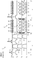
- Fig. 2 shows a sequence diagram 11 of a RESOLVE sequence which is known for example from Porter and Heidemann, High Resolution Diffusion-Weighted Imaging Using Readout-Segmented Echo-Planar Imaging, Parallel Imaging and a Two-Dimensional Navigator-Based Reacquisition, MRM, 62:468-475, 2009 .
- a diffusion preparation section includes an excitation pulse 12 and a refocusing pulse 13.
- Slice selection gradients 14 and 15 are applied at the same time to select a defined slice in a patient. It is known to use an additional slice rephrasing gradient 16 to compensate the dephasing fraction of the slice selection gradient 14.
- the diffusion encoding gradients 17, 18 and 19 before the refocusing pulse 13 and the respective gradients 20, 21 and 22 are also basically known.
- the excitation pulse 12 and the gradients 14 and 16 are part of an excitation phase 23 of the RESOLVE sequence.
- the following evolution phase 24 lasts to the end of the diffusion gradients 20, 21 and 22.
- a dephasing gradient 26 having different gradient moments by varying its strength puts the beginning of the readout in the readout direction to a desired position in k-space. This is shown in the following figure.
- a sinusoidal readout gradient 27 has a plurality of arcs 30, 31, 32, 33, 34, 35, 36 and 37. Every arc 30, 31, 32, 33, 34, 35, 36 and 37 encodes one partial line in a readout direction in the k-space.
- phase encoding gradients 38 shift the encoding for one step in phase encoding direction. Therefore the phase encoding gradients 38 are called blips or gradient blips.
- An initial phase encoding gradient 39 puts, similar to the dephasing gradient 26, the beginning of the readout in the phase encoding direction to a desired position in k-space.
- the readout phase 25 preferably all echo signals 40 of one so called segment are acquired. All signal echoes of an excitation cycle generate an echo train 41. At the end of the readout phase the encoding is put back to the starting point by applying a gradient 42 which has the same gradient moment as the dephasing gradient 26 but the opposite sign.
- a navigator phase 43 follows.
- the respective gradients 44, 45, 46 and 47 operate as described with regard to the readout phase 25.
- the echo signals 48 are generated using a refocusing pulse 49 and a slice selection gradient 50.
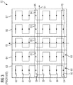
- Fig. 3 shows a k-space acquisition scheme used by the sequence 11.
- An axis 51 denotes the k(x) direction of the k-space 52 and an axis 53 the k(y) direction.
- the k(x) direction is also called readout direction and the k(y) direction phase encoding direction.
- the gradients 26 and 39 put the encoding to the first starting point 54.
- the partial line 55 is acquired while the arc 30 is applied, the partial line 56 at the same time as the arc 31 applied.
- the shift in phase encoding direction is achieved by one of the blips 38.
- the additional partial lines 57, 58, 59, 60 61 and 62 are created in the same way.
- the partial lines 55 to 62 or echo signals 40 constitute an echo train 41.
- the partial lines 55 to 62 cover a segment 63 of the k-space 52 which is separated in k(x) direction.
- an echo train 41 has all echo signals of a segment 63 to 67 of the k-space 52 a number of excitation cycles is needed that is the number of segments the k-space 52 has.
- the trajectories 68 and 69 of two adjacent segments e.g. the parts 63 and 64, have a gap for the sake of clarity.
- the echo signals of a k-space line cover the k-space 52 totally without gaps.
- Images are reconstructed using the echo signals of all excitation cycles having the same position in phase encoding direction as one k-space line.
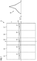
- Fig. 4 shows a sequence diagram 71 of an adjustment sequence according to the invention. Parts that correspond to Fig. 2 are labeled with the same reference characters.
- Diffusion gradients 17, 18, 19, 20, 21 and 22 as well as phase encoding gradients 38 are not applied. Then the central k lines in phase encoding direction are acquired.
- the arcs or gradient moments 30 to 37 of Fig. 2 are multiplied with a correction factor a + , a - , b + , b - , c + , c - , d + , and d - , respectively. That means that the gradient moment of arc 30 is multiplied with the correction factor a + , the gradient moment of arc 31 with the correction factor a - , and so on. Every gradient moment of an arc is multiplied with one of the correction factors. If the positive extreme value was set to 1, the correction factor can set a range from 1.03 to 0.99.
- a + could be 1.05, a - 1.04, b + 1.03, b - 1.02, c + 1.01, c - 1.00, d + 0.99 and d - 0.98.
- the range is preferably and independent of the number of echo signals from 0.98 to 1.04.
- the arcs or gradient moments have new character signs 72, 73, 74, 75, 76, 77, 78 and 79 to show the difference to Fig. 2 .
- the gradient moments 72 to 79 show a larger decrease than that the correction factors cause in reality to make the decrease visible.
- the arcs or gradient moments 72, 73, 74, 75, 76, 77, 78 and 79 show a larger decrease than that the correction factors cause in reality to make the decrease visible.
- One of the partial lines e.g. the partial line 55, is acquired n times, n being the number of echoes of the echo train 41, by executing one excitation cycle.
- the increase or decrease of the correction factors is advantageously linear, as shown by the numbers above.
- one echo train 41 is acquired.
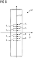
- the position of its echo signals 40 are shown in Fig. 5 .
- These combined k-space lines 85 are processed line by line. They can be Fourier transformed in one dimension. A zero-filling can be performed. Keeping the example of eight combined k-space lines one gets eight projections.
- the optimal correction factor can be found by an automatic examination of the projections. For example an edge detection algorithm can be executed. The least number/amplitude of edges shows the best correction factor.
- the first repetition is executed using a first gradient moment of the dephasing gradient 26 as a first operating parameter.
- the correction factors a - , b + , b - , c + , c - , d + , and d - are applied changing the gradient moment of the readout gradient being a second operating parameter being changed.
- the first echo signals 40 of every excitation cycle, which have been measured using the correction factor are combined to a combined k-space line 86. This is shown in Fig. 6 . Partial line 87 comes from the first repetition, partial line 88 from the second repetition, and so on.
- a second combined k-space line 92 is shown in Fig. 7 . There the second echoes of the five repetitions acquired using the correction factor a - are combined.
- the partial lines 93, 94, 95, 96 and 97 form the combined k-space line 92. They are measured as described.
- This combination can be performed for every echo signal 40 in an echo train 41.
- Every combined k-space line is then Fourier transformed to a projection 98 and 99, respectively.
- a combination of projections 87, 88, 89, 90, 91 into a combined k-space line 86 typically involves a gridding operation, i.e. accounting for the non-linear k-space acquisition during the sinusoidal gradient lobes.
- a first echo train 41 is acquired using the sequence 71 and having set a first dephasing gradient 26.
- the echo train 41 has e.g. eight echo signals which are acquired using the correction factors a + , a - , b + , b - , c + , c - , d + , and d - . All echo signals are located at the same position in k-space phase encoding direction and are in a first of the segments 62 to 67. That says that the gradient moment of the sinusoidal readout gradient being an operating parameter is changed within the excitation cycle.
- step S1-2 a second echo train 41 is acquired using the sequence 71 and having set a second dephasing gradient 26.
- the echo train 41 again has eight echo signals. All echo signals are located at the same position in k-space and are in a second of the segments 62 to 67.
- steps S1-3 to S1-n are performed using further gradient moments for the dephasing gradient 26 to cover some or all of the further segments 62 to 67.
- steps S1-1 to S1-5 would be performed to cover all segments.
- the gradient moment of the dephasing gradient is a second operating parameter which is changed between two excitation cycles. This change is not with regard to an optimization but due to the segmentation of the k-space.
- step S2 combined k-space lines 85, 86 and 92 are created by combining all first echo signals of the acquired echo trains to a first combined k-space line, all the second echo signals to a second combined k-space line, and so on. This presumes that the first echo signals are acquired with the correction factor the second ones with the correction factor a - . The main thing combining the echo signals is not the position of the echo but the correction factor.
- step S3 the combined k-space lines 85, 86 and 92 are Fourier transformed in one dimension to projections 98 and 99.
- step S4 an edge detection algorithm determines the amplitude of the edges of every projection 98 and 99.
- step S5 the gradient moment and correction factor, respectively, creating the least amplitude of the amplitudes of the edges is determined.
- This method can be performed just before a RESOLVE measurement taking only about a few seconds. Then the images have less artifacts.
Landscapes
- Physics & Mathematics (AREA)
- General Physics & Mathematics (AREA)
- Condensed Matter Physics & Semiconductors (AREA)
- Engineering & Computer Science (AREA)
- High Energy & Nuclear Physics (AREA)
- Signal Processing (AREA)
- Nuclear Medicine, Radiotherapy & Molecular Imaging (AREA)
- Radiology & Medical Imaging (AREA)
- General Health & Medical Sciences (AREA)
- Health & Medical Sciences (AREA)
- Nonlinear Science (AREA)
- Artificial Intelligence (AREA)
- Computer Vision & Pattern Recognition (AREA)
- Magnetic Resonance Imaging Apparatus (AREA)
Priority Applications (3)
| Application Number | Priority Date | Filing Date | Title |
|---|---|---|---|
| EP19151327.4A EP3680680A1 (de) | 2019-01-11 | 2019-01-11 | Verfahren zum erhalt eines optimierten betriebsparameters, speichermedium und magnetresonanzgerät |
| CN202010017079.4A CN111435156B (zh) | 2019-01-11 | 2020-01-08 | 用于获得操作参数的方法、存储介质和磁共振装置 |
| US16/738,185 US11181596B2 (en) | 2019-01-11 | 2020-01-09 | Method for obtaining an operating parameter, storage medium, and magnetic resonance apparatus |
Applications Claiming Priority (1)
| Application Number | Priority Date | Filing Date | Title |
|---|---|---|---|
| EP19151327.4A EP3680680A1 (de) | 2019-01-11 | 2019-01-11 | Verfahren zum erhalt eines optimierten betriebsparameters, speichermedium und magnetresonanzgerät |
Publications (1)
| Publication Number | Publication Date |
|---|---|
| EP3680680A1 true EP3680680A1 (de) | 2020-07-15 |
Family
ID=65019347
Family Applications (1)
| Application Number | Title | Priority Date | Filing Date |
|---|---|---|---|
| EP19151327.4A Withdrawn EP3680680A1 (de) | 2019-01-11 | 2019-01-11 | Verfahren zum erhalt eines optimierten betriebsparameters, speichermedium und magnetresonanzgerät |
Country Status (3)
| Country | Link |
|---|---|
| US (1) | US11181596B2 (de) |
| EP (1) | EP3680680A1 (de) |
| CN (1) | CN111435156B (de) |
Cited By (1)
| Publication number | Priority date | Publication date | Assignee | Title |
|---|---|---|---|---|
| US20260056344A1 (en) * | 2024-08-26 | 2026-02-26 | Schlumberger Technology Corporation | Nmr echo signal correction techniques |
Citations (2)
| Publication number | Priority date | Publication date | Assignee | Title |
|---|---|---|---|---|
| US20030109781A1 (en) * | 2001-12-11 | 2003-06-12 | Weiguo Zhang | Sequence preconditioning for ultra-fast magnetic resonance imaging |
| US20060176055A1 (en) * | 2005-02-10 | 2006-08-10 | Kabushiki Kaisha Toshiba | Magnetic resonance imaging apparatus and its control method |
Family Cites Families (21)
| Publication number | Priority date | Publication date | Assignee | Title |
|---|---|---|---|---|
| DE4438488A1 (de) * | 1994-10-28 | 1996-05-02 | Philips Patentverwaltung | MR-Verfahren und Anordnung zur Durchführung desselben |
| JP3505294B2 (ja) * | 1995-03-28 | 2004-03-08 | ジーイー横河メディカルシステム株式会社 | Mri装置 |
| JP3384944B2 (ja) * | 1996-07-11 | 2003-03-10 | ジーイー横河メディカルシステム株式会社 | Mri装置 |
| US6188219B1 (en) * | 1999-01-22 | 2001-02-13 | The Johns Hopkins University | Magnetic resonance imaging method and apparatus and method of calibrating the same |
| US20020002331A1 (en) * | 1999-05-14 | 2002-01-03 | Harvey Ellis Cline | Mr imaging with partial k-space acquisition using spiral scanning |
| DE10028171B4 (de) * | 2000-06-09 | 2006-12-28 | Forschungszentrum Jülich GmbH | Bildgebungsverfahren und Kernspinresonanztomograph |
| US7027853B2 (en) * | 2002-09-26 | 2006-04-11 | Board Of Regents, The University Of Texas System | Data acquisition method and apparatus for MR imaging |
| EP1471362A1 (de) * | 2003-04-24 | 2004-10-27 | Universiteit Utrecht Holding B.V. | Selektive Kernspintomographie von Abweichungen der magnetischen Suszeptibilität |
| US7300994B2 (en) * | 2004-11-22 | 2007-11-27 | Cornell Research Foundation, Inc. | Isotactic polypropylene containing polymers |
| CN101375173A (zh) * | 2006-01-30 | 2009-02-25 | 皇家飞利浦电子股份有限公司 | 用于介入乳房磁共振成像的自动系统 |
| DE102010012948B4 (de) * | 2010-03-26 | 2012-04-26 | Siemens Aktiengesellschaft | Verfahren zum Ermitteln von Phasenkorrekturparametern und Magnetresonanzvorrichtung |
| CN102525460B (zh) * | 2010-12-29 | 2013-11-06 | 西门子(深圳)磁共振有限公司 | 一种磁共振成像水脂图像辨析方法及装置 |
| CN102841329B (zh) * | 2011-06-24 | 2016-03-30 | 西门子(深圳)磁共振有限公司 | 磁共振信号处理方法及装置 |
| CN103257333B (zh) * | 2012-02-17 | 2016-04-13 | 西门子(深圳)磁共振有限公司 | 一种磁共振成像中的水脂分离成像方法及装置 |
| US9632162B2 (en) * | 2013-12-06 | 2017-04-25 | Toshiba Medical Systems Corporation | Method of, and apparatus for, correcting distortion in medical images |
| EP2933651B1 (de) * | 2014-04-17 | 2020-03-18 | Albert-Ludwigs-Universität Freiburg | MRI-Verfahren zur hybriden Datenerfassung in 3D-TSE |
| US10175328B2 (en) * | 2014-08-25 | 2019-01-08 | The Brigham And Women's Hospital | System and method for reconstructing ghost-free images from data acquired using simultaneous multislice magnetic resonance imaging |
| WO2016166119A1 (en) * | 2015-04-14 | 2016-10-20 | Koninklijke Philips N.V. | Magnetic resonance fingerprinting with reduced sensitivity to inhomogeneities in the main magnetic field |
| SE1551719A1 (sv) * | 2015-12-29 | 2016-12-20 | Cr Dev Ab | Method of extracting information about a sample by nuclear magnetic resonance measurements |
| CN105806870B (zh) * | 2016-03-11 | 2017-10-10 | 厦门大学 | 一种抵抗磁场不均匀的纯化学位移核磁共振谱方法 |
| DE102017222359B4 (de) | 2017-12-11 | 2021-01-28 | Siemens Healthcare Gmbh | Automatische Bestimmung von Korrekturfaktoren für eine Magnetresonanzanlage |
-
2019
- 2019-01-11 EP EP19151327.4A patent/EP3680680A1/de not_active Withdrawn
-
2020
- 2020-01-08 CN CN202010017079.4A patent/CN111435156B/zh active Active
- 2020-01-09 US US16/738,185 patent/US11181596B2/en not_active Expired - Fee Related
Patent Citations (2)
| Publication number | Priority date | Publication date | Assignee | Title |
|---|---|---|---|---|
| US20030109781A1 (en) * | 2001-12-11 | 2003-06-12 | Weiguo Zhang | Sequence preconditioning for ultra-fast magnetic resonance imaging |
| US20060176055A1 (en) * | 2005-02-10 | 2006-08-10 | Kabushiki Kaisha Toshiba | Magnetic resonance imaging apparatus and its control method |
Non-Patent Citations (1)
| Title |
|---|
| PORTER; HEIDEMANN: "High Resolution Diffusion-Weighted Imaging Using Readout-Segmented Echo-Planar Imaging, Parallel Imaging and a Two-Dimensional Navigator-Based Reacquisition", MRM, vol. 62, 2009, pages 468 - 475, XP055130037, DOI: doi:10.1002/mrm.22024 |
Cited By (1)
| Publication number | Priority date | Publication date | Assignee | Title |
|---|---|---|---|---|
| US20260056344A1 (en) * | 2024-08-26 | 2026-02-26 | Schlumberger Technology Corporation | Nmr echo signal correction techniques |
Also Published As
| Publication number | Publication date |
|---|---|
| US11181596B2 (en) | 2021-11-23 |
| CN111435156A (zh) | 2020-07-21 |
| CN111435156B (zh) | 2022-08-19 |
| US20200225305A1 (en) | 2020-07-16 |
Similar Documents
| Publication | Publication Date | Title |
|---|---|---|
| US8076935B2 (en) | Magnetic resonance imaging (MRI) using SPIR and/or chess suppression pulses | |
| US7057388B2 (en) | Magnetic resonance method and device | |
| US9046590B2 (en) | Magnetic resonance imaging apparatus phase correction using one or more prescans with identical readout and slice gradients | |
| US8934691B2 (en) | System for motion compensated MR parallel imaging | |
| EP2320245A1 (de) | MR-Bildgebung mithilfe von Navigatoren | |
| US20150253408A1 (en) | Method and apparatus for magnetic resonance imaging | |
| US9581667B2 (en) | Method and magnetic resonance system to implement a multi-echo measurement sequence | |
| US6331777B1 (en) | Magnetic resonance method and device | |
| CN113970715B (zh) | 借助于磁共振设备记录测量数据的方法和磁共振设备 | |
| US10067209B2 (en) | Magnetic resonance imaging apparatus | |
| US6489770B1 (en) | Nuclear magnetic resonance imaging apparatus | |
| US10725134B2 (en) | Method and magnetic resonance apparatus for optimizing the simultaneous acquisition of magnetic resonance data from multiple slabs or slices | |
| US11119174B2 (en) | Method for obtaining a correction factor, storage medium, and magnetic resonance apparatus | |
| US11181596B2 (en) | Method for obtaining an operating parameter, storage medium, and magnetic resonance apparatus | |
| JP2005152175A (ja) | 磁気共鳴撮像装置および方法 | |
| EP3185029A1 (de) | Mr-bildgebung mit propellererfassung mit t2-zerfallskorrektur | |
| JP2001112735A (ja) | 磁気共鳴イメージング装置 | |
| US11016155B2 (en) | Method, apparatus and storage medium for recording a magnetic resonance dataset | |
| US20050116710A1 (en) | Magnetic resonance imaging | |
| US20030210044A1 (en) | Missing pulse steady state free precession | |
| US11215684B2 (en) | Method for obtaining a magnetic resonance dataset, storage medium and magnetic resonance apparatus | |
| CN115308658B (zh) | 用于自适应重建mr数据的方法、重建单元和磁共振设备 | |
| EP3761261B1 (de) | Kombinierung von anatomischen bilddatensätzen zu einem kombinierten bilddatensatz | |
| CN121091176A (zh) | 借助于磁共振技术对测量数据的优化的记录 | |
| CN121080946A (zh) | 改进的petra方法 |
Legal Events
| Date | Code | Title | Description |
|---|---|---|---|
| PUAI | Public reference made under article 153(3) epc to a published international application that has entered the european phase |
Free format text: ORIGINAL CODE: 0009012 |
|
| STAA | Information on the status of an ep patent application or granted ep patent |
Free format text: STATUS: REQUEST FOR EXAMINATION WAS MADE |
|
| 17P | Request for examination filed |
Effective date: 20191004 |
|
| AK | Designated contracting states |
Kind code of ref document: A1 Designated state(s): AL AT BE BG CH CY CZ DE DK EE ES FI FR GB GR HR HU IE IS IT LI LT LU LV MC MK MT NL NO PL PT RO RS SE SI SK SM TR |
|
| AX | Request for extension of the european patent |
Extension state: BA ME |
|
| STAA | Information on the status of an ep patent application or granted ep patent |
Free format text: STATUS: EXAMINATION IS IN PROGRESS |
|
| 17Q | First examination report despatched |
Effective date: 20220304 |
|
| STAA | Information on the status of an ep patent application or granted ep patent |
Free format text: STATUS: THE APPLICATION IS DEEMED TO BE WITHDRAWN |
|
| 18D | Application deemed to be withdrawn |
Effective date: 20230801 |