EP3680720B1 - Récipient d'approvisionnement en révélateur - Google Patents
Récipient d'approvisionnement en révélateur Download PDFInfo
- Publication number
- EP3680720B1 EP3680720B1 EP19180456.6A EP19180456A EP3680720B1 EP 3680720 B1 EP3680720 B1 EP 3680720B1 EP 19180456 A EP19180456 A EP 19180456A EP 3680720 B1 EP3680720 B1 EP 3680720B1
- Authority
- EP
- European Patent Office
- Prior art keywords
- developer
- gas
- connecting cylinder
- powder discharging
- stirring
- Prior art date
- Legal status (The legal status is an assumption and is not a legal conclusion. Google has not performed a legal analysis and makes no representation as to the accuracy of the status listed.)
- Not-in-force
Links
Images


Classifications
-
- G—PHYSICS
- G03—PHOTOGRAPHY; CINEMATOGRAPHY; ANALOGOUS TECHNIQUES USING WAVES OTHER THAN OPTICAL WAVES; ELECTROGRAPHY; HOLOGRAPHY
- G03G—ELECTROGRAPHY; ELECTROPHOTOGRAPHY; MAGNETOGRAPHY
- G03G15/00—Apparatus for electrographic processes using a charge pattern
- G03G15/06—Apparatus for electrographic processes using a charge pattern for developing
- G03G15/08—Apparatus for electrographic processes using a charge pattern for developing using a solid developer, e.g. powder developer
- G03G15/0822—Arrangements for preparing, mixing, supplying or dispensing developer
- G03G15/0865—Arrangements for supplying new developer
- G03G15/0867—Arrangements for supplying new developer cylindrical developer cartridges, e.g. toner bottles for the developer replenishing opening
- G03G15/0868—Toner cartridges fulfilling a continuous function within the electrographic apparatus during the use of the supplied developer material, e.g. toner discharge on demand, storing residual toner, acting as an active closure for the developer replenishing opening
-
- G—PHYSICS
- G03—PHOTOGRAPHY; CINEMATOGRAPHY; ANALOGOUS TECHNIQUES USING WAVES OTHER THAN OPTICAL WAVES; ELECTROGRAPHY; HOLOGRAPHY
- G03G—ELECTROGRAPHY; ELECTROPHOTOGRAPHY; MAGNETOGRAPHY
- G03G15/00—Apparatus for electrographic processes using a charge pattern
- G03G15/06—Apparatus for electrographic processes using a charge pattern for developing
- G03G15/08—Apparatus for electrographic processes using a charge pattern for developing using a solid developer, e.g. powder developer
- G03G15/0822—Arrangements for preparing, mixing, supplying or dispensing developer
- G03G15/0865—Arrangements for supplying new developer
- G03G15/0867—Arrangements for supplying new developer cylindrical developer cartridges, e.g. toner bottles for the developer replenishing opening
- G03G15/087—Developer cartridges having a longitudinal rotational axis, around which at least one part is rotated when mounting or using the cartridge
- G03G15/0872—Developer cartridges having a longitudinal rotational axis, around which at least one part is rotated when mounting or using the cartridge the developer cartridges being generally horizontally mounted parallel to its longitudinal rotational axis
-
- B—PERFORMING OPERATIONS; TRANSPORTING
- B65—CONVEYING; PACKING; STORING; HANDLING THIN OR FILAMENTARY MATERIAL
- B65B—MACHINES, APPARATUS OR DEVICES FOR, OR METHODS OF, PACKAGING ARTICLES OR MATERIALS; UNPACKING
- B65B1/00—Packaging fluent solid material, e.g. powders, granular or loose fibrous material, loose masses of small articles, in individual containers or receptacles, e.g. bags, sacks, boxes, cartons, cans, or jars
- B65B1/20—Reducing volume of filled material
- B65B1/26—Reducing volume of filled material by pneumatic means, e.g. suction
-
- B—PERFORMING OPERATIONS; TRANSPORTING
- B65—CONVEYING; PACKING; STORING; HANDLING THIN OR FILAMENTARY MATERIAL
- B65B—MACHINES, APPARATUS OR DEVICES FOR, OR METHODS OF, PACKAGING ARTICLES OR MATERIALS; UNPACKING
- B65B1/00—Packaging fluent solid material, e.g. powders, granular or loose fibrous material, loose masses of small articles, in individual containers or receptacles, e.g. bags, sacks, boxes, cartons, cans, or jars
- B65B1/30—Devices or methods for controlling or determining the quantity or quality or the material fed or filled
- B65B1/36—Devices or methods for controlling or determining the quantity or quality or the material fed or filled by volumetric devices or methods
- B65B1/38—Devices or methods for controlling or determining the quantity or quality or the material fed or filled by volumetric devices or methods by pistons co-operating with measuring chambers
-
- G—PHYSICS
- G01—MEASURING; TESTING
- G01F—MEASURING VOLUME, VOLUME FLOW, MASS FLOW OR LIQUID LEVEL; METERING BY VOLUME
- G01F11/00—Apparatus requiring external operation adapted at each repeated and identical operation to measure and separate a predetermined volume of fluid or fluent solid material from a supply or container, without regard to weight, and to deliver it
- G01F11/10—Apparatus requiring external operation adapted at each repeated and identical operation to measure and separate a predetermined volume of fluid or fluent solid material from a supply or container, without regard to weight, and to deliver it with measuring chambers moved during operation
- G01F11/12—Apparatus requiring external operation adapted at each repeated and identical operation to measure and separate a predetermined volume of fluid or fluent solid material from a supply or container, without regard to weight, and to deliver it with measuring chambers moved during operation of the valve type, i.e. the separating being effected by fluid-tight or powder-tight movements
- G01F11/14—Apparatus requiring external operation adapted at each repeated and identical operation to measure and separate a predetermined volume of fluid or fluent solid material from a supply or container, without regard to weight, and to deliver it with measuring chambers moved during operation of the valve type, i.e. the separating being effected by fluid-tight or powder-tight movements wherein the measuring chamber reciprocates
- G01F11/18—Apparatus requiring external operation adapted at each repeated and identical operation to measure and separate a predetermined volume of fluid or fluent solid material from a supply or container, without regard to weight, and to deliver it with measuring chambers moved during operation of the valve type, i.e. the separating being effected by fluid-tight or powder-tight movements wherein the measuring chamber reciprocates for fluent solid material
-
- G—PHYSICS
- G01—MEASURING; TESTING
- G01F—MEASURING VOLUME, VOLUME FLOW, MASS FLOW OR LIQUID LEVEL; METERING BY VOLUME
- G01F11/00—Apparatus requiring external operation adapted at each repeated and identical operation to measure and separate a predetermined volume of fluid or fluent solid material from a supply or container, without regard to weight, and to deliver it
- G01F11/28—Apparatus requiring external operation adapted at each repeated and identical operation to measure and separate a predetermined volume of fluid or fluent solid material from a supply or container, without regard to weight, and to deliver it with stationary measuring chambers having constant volume during measurement
- G01F11/282—Apparatus requiring external operation adapted at each repeated and identical operation to measure and separate a predetermined volume of fluid or fluent solid material from a supply or container, without regard to weight, and to deliver it with stationary measuring chambers having constant volume during measurement for fluent solid material not provided for in G01F11/34, G01F11/40, G01F11/46
-
- G—PHYSICS
- G03—PHOTOGRAPHY; CINEMATOGRAPHY; ANALOGOUS TECHNIQUES USING WAVES OTHER THAN OPTICAL WAVES; ELECTROGRAPHY; HOLOGRAPHY
- G03G—ELECTROGRAPHY; ELECTROPHOTOGRAPHY; MAGNETOGRAPHY
- G03G15/00—Apparatus for electrographic processes using a charge pattern
- G03G15/06—Apparatus for electrographic processes using a charge pattern for developing
- G03G15/08—Apparatus for electrographic processes using a charge pattern for developing using a solid developer, e.g. powder developer
- G03G15/0822—Arrangements for preparing, mixing, supplying or dispensing developer
- G03G15/0865—Arrangements for supplying new developer
- G03G15/0867—Arrangements for supplying new developer cylindrical developer cartridges, e.g. toner bottles for the developer replenishing opening
- G03G15/087—Developer cartridges having a longitudinal rotational axis, around which at least one part is rotated when mounting or using the cartridge
-
- G—PHYSICS
- G03—PHOTOGRAPHY; CINEMATOGRAPHY; ANALOGOUS TECHNIQUES USING WAVES OTHER THAN OPTICAL WAVES; ELECTROGRAPHY; HOLOGRAPHY
- G03G—ELECTROGRAPHY; ELECTROPHOTOGRAPHY; MAGNETOGRAPHY
- G03G15/00—Apparatus for electrographic processes using a charge pattern
- G03G15/06—Apparatus for electrographic processes using a charge pattern for developing
- G03G15/08—Apparatus for electrographic processes using a charge pattern for developing using a solid developer, e.g. powder developer
- G03G15/0822—Arrangements for preparing, mixing, supplying or dispensing developer
- G03G15/0877—Arrangements for metering and dispensing developer from a developer cartridge into the development unit
-
- G—PHYSICS
- G03—PHOTOGRAPHY; CINEMATOGRAPHY; ANALOGOUS TECHNIQUES USING WAVES OTHER THAN OPTICAL WAVES; ELECTROGRAPHY; HOLOGRAPHY
- G03G—ELECTROGRAPHY; ELECTROPHOTOGRAPHY; MAGNETOGRAPHY
- G03G15/00—Apparatus for electrographic processes using a charge pattern
- G03G15/06—Apparatus for electrographic processes using a charge pattern for developing
- G03G15/08—Apparatus for electrographic processes using a charge pattern for developing using a solid developer, e.g. powder developer
- G03G15/0822—Arrangements for preparing, mixing, supplying or dispensing developer
- G03G15/0887—Arrangements for conveying and conditioning developer in the developing unit, e.g. agitating, removing impurities or humidity
- G03G15/0889—Arrangements for conveying and conditioning developer in the developing unit, e.g. agitating, removing impurities or humidity for agitation or stirring
-
- G—PHYSICS
- G03—PHOTOGRAPHY; CINEMATOGRAPHY; ANALOGOUS TECHNIQUES USING WAVES OTHER THAN OPTICAL WAVES; ELECTROGRAPHY; HOLOGRAPHY
- G03G—ELECTROGRAPHY; ELECTROPHOTOGRAPHY; MAGNETOGRAPHY
- G03G15/00—Apparatus for electrographic processes using a charge pattern
- G03G15/06—Apparatus for electrographic processes using a charge pattern for developing
- G03G15/08—Apparatus for electrographic processes using a charge pattern for developing using a solid developer, e.g. powder developer
- G03G15/0822—Arrangements for preparing, mixing, supplying or dispensing developer
- G03G15/0887—Arrangements for conveying and conditioning developer in the developing unit, e.g. agitating, removing impurities or humidity
- G03G15/0891—Arrangements for conveying and conditioning developer in the developing unit, e.g. agitating, removing impurities or humidity for conveying or circulating developer, e.g. augers
-
- G—PHYSICS
- G03—PHOTOGRAPHY; CINEMATOGRAPHY; ANALOGOUS TECHNIQUES USING WAVES OTHER THAN OPTICAL WAVES; ELECTROGRAPHY; HOLOGRAPHY
- G03G—ELECTROGRAPHY; ELECTROPHOTOGRAPHY; MAGNETOGRAPHY
- G03G21/00—Arrangements not provided for by groups G03G13/00 - G03G19/00, e.g. cleaning, elimination of residual charge
- G03G21/20—Humidity or temperature control also ozone evacuation; Internal apparatus environment control
- G03G21/206—Conducting air through the machine, e.g. for cooling, filtering, removing gases like ozone
-
- G—PHYSICS
- G03—PHOTOGRAPHY; CINEMATOGRAPHY; ANALOGOUS TECHNIQUES USING WAVES OTHER THAN OPTICAL WAVES; ELECTROGRAPHY; HOLOGRAPHY
- G03G—ELECTROGRAPHY; ELECTROPHOTOGRAPHY; MAGNETOGRAPHY
- G03G2215/00—Apparatus for electrophotographic processes
- G03G2215/06—Developing structures, details
- G03G2215/066—Toner cartridge or other attachable and detachable container for supplying developer material to replace the used material
- G03G2215/0663—Toner cartridge or other attachable and detachable container for supplying developer material to replace the used material having a longitudinal rotational axis, around which at least one part is rotated when mounting or using the cartridge
- G03G2215/0665—Generally horizontally mounting of said toner cartridge parallel to its longitudinal rotational axis
- G03G2215/0668—Toner discharging opening at one axial end
Definitions
- the present invention relates to the field of developing equipment, and particularly to a developer supply container.
- the image forming device includes an image carrier, a developing device, and a developer supply container for accommodating the developer.
- the developer supply container is provided with a developer discharging port for supplying the developer to the developing device.
- the developer supply container mountable/detachable on the developer replenishing device includes: a container body for accommodating the developer; a discharging port for discharging the developer stored in the container body; a holding member to which a driving force is input from the developer replenishing device; a pumping part which is operated according to the driving force received by the holding member to repeatedly and alternately switch the internal pressure of the container body between a state with a pressure lower than the ambient pressure and a state with a pressure higher than the ambient pressure; and a managing part composed of the holding member and a locking member for managing the position of the pump part at the start of the operation, so that air is drawn into the container body from the discharging port during the period of the first operation cycle of the pump part.
- the developer supply container provided by the above patent can achieve a pressure inside the developer supply container lower than ambient pressure by the driving of the pump, so that the air flows into the developer replenishing container, thus enhancing the fluidity of the developer.
- the pressure inside the developer supply container also may be higher than the ambient pressure with the driving of the pump, so that the developer can be discharged and intermittently supplied to the developer.
- the developer supply container of the above structure often causes the situation where the developer is over compacted by slight impact between the developer and the developer supply container due to the vibration during the transportation or storage.
- a large amount of developer may be completely discharged at one time when the developer is discharged, which is generally known as a gushing phenomenon.
- the developer supply container of the above structure often uses a single developer discharging port for alternate air inhale and exhale during operation.
- Such an air inhale and exhale method will slow down the discharge speed of the developer in a certain extent, and transport the developer at the nearby region of the developer discharging port into the developer supply container while inhaling air from the developer discharging port, thereby causing the lack of force for discharging the developer.
- the present invention provides a developer supply container according to the appended claims.
- the present invention provides a developer supply container which includes a rotating container for conveying a developer, and an intermittent regulator for intermittently supplying gas into the rotating container and regulating an internal pressure of the rotating container.
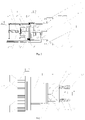
- One end of the rotating container is provided with a powder discharging bin, and a part of an inner space of the powder discharging bin forms a gas mixing space for accommodating the developer.
- a bottom of the powder discharging bin is provided with a powder discharging port for discharging the developer, and the powder discharging port is located below the gas mixing space.
- the intermittent regulator is configured to intermittently supply a fixed amount of gas to the gas mixing space, and after the fixed amount of gas is mixed with the developer, the developer in the gas mixing space discharges from the powder discharging port with the fixed amount of gas.
- the intermittent regulator can periodically supply the fixed amount of gas to the gas mixing space, the fixed amount of gas can effectively ensure a stable air pressure inside the developer supply container.
- the circumstances of higher or lower air pressure inside the developer supply container do not tend to occur like the case of using a pump, thereby ensuring that the developer does not become over compacted, i.e., no gushing phenomenon occurs, and realizing a high precision replenishment amount of the developer.
- the rotating container includes a connecting cylinder and a receiving drum.
- One end of the connecting cylinder is rotatably connected to one end of the powder discharging bin, and the other end of the connecting cylinder is connected to the receiving drum by a threaded connection.
- the connecting cylinder is configured to connect to the powder discharging bin and the receiving drum, effectively. After the connecting cylinder and the receiving drum are connected into one single piece by the threaded connection, when the connecting cylinder and the receiving drum rotate, the developer continuously flows to the powder discharging bin, thereby ensuring a continuous supply of the developer in the powder discharging bin.
- the intermittent regulator includes a cam piston having a cam surface, one end of the connecting cylinder is provided with a first stirring plate, and an end surface of one end of the first stirring plate is in contact with the cam surface of the cam piston.
- the first stirring plate drives the cam piston to perform a reciprocating translational motion along an inner wall of the powder discharging bin.
- the first stirring plate can rotate along with the connecting cylinder, so as to continuously push the cam piston to perform the reciprocating translational motion.
- the intermittent regulator further includes a spring
- the cam surface is located at one side of the cam piston
- the other side of the cam piston is provided with at least one sliding rod.
- the other end of the powder discharging bin is provided with a cover
- a sliding column corresponding to the sliding rod is provided on an inner wall of the cover
- one end of the sliding rod is inserted into a sliding groove inside the sliding column
- the sliding rod matches with the sliding column in a sliding manner.
- the spring is sleeved on the sliding column, one end of the spring is in contact with the cover, and the other end of the spring is in contact with a side wall of the other side of the cam piston.
- the cam piston Since the first stirring plate merely rotates without an axial displacement, after an axial displacement of the cam piston occurs, the cam piston is returned under an action of the spring, thereby ensuring a smooth proceeding of the reciprocating motion of the cam piston.
- the sliding rod and the sliding column further have a guiding function, which effectively ensures the stability and reliability during the reciprocating motion of the cam piston and reduces the possibility of deviation in the reciprocating motion of the cam piston.
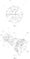
- an inner wall of the other side of the cam piston, the inner wall of the powder discharging bin, and the inner wall of the cover enclose a gas storage space for accommodating the fixed amount of gas.
- a middle part of the cam piston is provided with a first unidirectional patch valve for the fixed amount of gas to enter the gas mixing space, unidirectionally, and a middle part of the cover is provided with a second unidirectional patch valve for the fixed amount of gas to enter the gas storage space, unidirectionally.
- the first unidirectional patch valve When an end portion of the first stirring plate moves from a low point of the cam surface of the cam piston to a top point of the cam surface of the cam piston, the first unidirectional patch valve is opened because an air pressure in the gas storage space is higher than an air pressure in the gas mixing space, so that the fixed amount of gas flows from the gas storage space to the gas mixing space.
- the second unidirectional patch valve is opened because an external atmospheric pressure outside the powder discharging bin is greater than air pressure in the gas storage space, so that the fixed amount of gas flows from an exterior of the powder discharging bin to the gas storage space.
- a drum connecting port is provided on the connecting cylinder at a side of a joint between the receiving drum and the connecting cylinder.
- a drive gear for driving a rotation of the connecting cylinder and the receiving drum is provided on the drum connecting port.
- An internal thread is provided inside the drum connecting port for screwing the receiving drum into the connecting cylinder to facilitate an installation and disassembly of the receiving drum.
- the internal thread inside the connecting cylinder and a thread on the receiving drum are connected to each other in a left-hand thread connection.
- a rotation direction of the drive gear is consistent with a screwing direction of the left-hand thread connection. Since the connecting cylinder rotates together with the receiving drum, during the rotation, it should ensure that the rotation direction of the driving gear is consistent with the screwing direction of the left-hand thread connection, so as to ensure that the threaded connection between the connecting cylinder and the receiving drum is not being loosened due to the rotation of the connecting cylinder and the receiving drum.
- a second stirring frame is provided inside the connecting cylinder, and the other end of the first stirring plate is fixedly connected to a distal end of the second stirring frame.
- the second stirring frame is located inside the connecting cylinder and is matched with the connecting cylinder in a plug-in manner.
- the second stirring frame can effectively connect the first stirring plate and a third stirring plate and can further assist the conveying of the developer in the connecting cylinder.
- the developer is conveyed into the gas mixing space between the connecting cylinder and the powder discharging bin.
- the other end of the connecting cylinder is provided with a plurality of third stirring plates, and one end of each of the third stirring plates is fixedly connected to an initial end of the second stirring frame.
- the other end of each of the plurality of third stirring plates is a free end and is inserted into the receiving drum.
- One end of the receiving drum has a tapered neck part, and the plurality of third stirring plates can effectively convey the developer at the tapered neck part into the connecting cylinder to ensure a smooth flow of the developer from the receiving drum to the connecting cylinder.
- the plurality of the third stirring plates are provided in pairs, and a straight line distance between farthest ends of two third stirring plates of each pair of the plurality of the third stirring plates is greater than a diameter of a drum body of the receiving drum.
- the straight line distance between the farthest ends of the two third stirring plates being greater than the diameter of the drum body of the receiving drum makes sure that the third stirring plates are in a close fit with an inner wall of the tapered neck part of the receiving drum, so a gap between the third stirring plates and the inner wall of the tapered neck part can be avoided and the situation that the force for conveying the developer is insufficient can be avoided.
- an opening angle is formed between the two third stirring plates of each pair of the plurality of the third stirring plates, and a value of the opening angle should be equal to a value of a cone angle of the tapered neck part of the receiving drum.
- the value of the opening angle between the two third stirring plates of each pair may be slightly larger than the value of the cone angle of the tapered neck part of the receiving drum.
- the second stirring frame is configured as a multi-layer spiral stirring plate structure, at least one sliding strip having an elongated shape is provided at an outer side of the multi-layer spiral stirring plate structure, and at least one sliding groove matched with the sliding strip is provided inside the connecting cylinder.
- the second stirring frame is detachably connected to the connecting cylinder by a sliding of the at least one sliding strip and the at least one sliding groove.
- the plug-in connection between the second stirring frame and the connecting cylinder can be realized by the sliding of a plurality of sliding strips and a plurality of sliding grooves, so the detachable connection between the stirring plate component and the connecting cylinder can be realized easily.
- a plurality of guiding protrusions for conveying the developer are provided on the receiving drum.
- the plurality of guiding protrusions drive the developer to move toward one end of the receiving drum.
- the plurality of guiding protrusions generate a certain driving force for the developer, and a component of the driving force can push the developer to displace in an axial direction, so that the developer can move to the joint of the receiving drum and the connecting cylinder.
- a first sealing ring is provided at a sliding interface between the cam piston and the inner wall of the powder discharging bin, and the first sealing ring is sleeved in a sealing groove around a periphery of the cam piston.
- one end of the connecting cylinder is located in the powder discharging bin, and one end portion of the connecting cylinder is provided with a second sealing ring.
- the gas mixing space is configured as a closed space formed by the first sealing ring, the second sealing ring, the inner wall of the powder discharging bin, and the cam surface of the cam piston.
- the pressure inside the closed space is relatively constant, thereby ensuring a continual and steady flow of the developer.
- both sides of the first stirring plate are provided with scrapers for scraping the developer on the inner wall of the powder discharging bin.
- sides of the plurality of the third stirring plates are fitted with the inner wall of the tapered neck part of the receiving drum, so the developer can be efficiently conveyed to the connecting cylinder.
- the present invention has the followings advantages.
- the developer supply container provided by the present invention is provided with a rotating container for conveying the developer and an intermittent regulator for intermittently supplying the gas to the rotating container and adjusting the internal pressure of the rotating container to intermittently supply a fixed amount of gas to the gas mixing space. After the fixed amount of gas is mixed with the developer, the developer in the gas mixing space follows the fixed amount of gas and flows out from the powder discharging port.
- the developer supply container provided by the present invention can continuously and stably replenish the developer to the image forming device under any storage environment or operating environment, which can effectively maintain a stable pressure inside the developer supply container, and achieve a high precision replenishment amount for the developer.
- the present invention further provides a stirring plate component which functions well as a conveyor. The stirring plate component can make sure that the developer in the rotating container flows to the powder discharging bin continuously and stably, thereby ensuring an effective supply of the developer to the gas mixing space.
- a developer supply container provided by the present embodiment includes the rotating container 1 for conveying a developer, and the intermittent regulator 2 for intermittently supplying gas into the rotating container 1 and regulating an internal pressure of the rotating container 1.
- the rotating container 1 has a dual function of conveying and storing the developer.
- One end of the rotating container 1 is provided with the powder discharging bin 3, and a part of the internal space of the powder discharging bin 3 forms the gas mixing space 31 for accommodating the developer.
- the bottom of the powder discharging bin 3 is provided with the powder discharging port 32 for the developer to flow out, the powder discharging port 32 is located below the gas mixing space 31, and the powder discharging port 32 is located at the bottom of the powder discharging bin 3 as well.
- the developer is conveyed to the gas mixing space 31 in the powder discharging bin 3 under the rotation of the rotating container 1, while the intermittent regulator 2 intermittently supplies a fixed amount of gas to the gas mixing space 31.
- the developer in the gas mixing space 31 discharges from the powder discharging port 32 with the fixed amount of gas. Since the intermittent regulator 2 can periodically supply the fixed amount of gas to the gas mixing space 31, the fixed amount of gas can effectively ensure a stability of the air pressure inside the developer supply container, and the circumstances of higher or lower air pressure inside the developer supply container do not tend to occur like the case of using a pump, because the air charging and discharging of the pump have an inevitable lag.
- the intermittent regulator 2 in the present embodiment is capable of intermittently supplying the fixed amount of gas, while the intermittent period and the supply amount of the gas in the prior art are difficult to control, thus leading to over compact of the developer.
- the rotating container 1 in order to facilitate the developer in the rotating container 1 to flow into the powder discharging bin 3, further, the rotating container 1 includes the connecting cylinder 11 and the receiving drum 12.
- One end of the connecting cylinder 11 is rotatably connected to one end of the powder discharging bin 3, and the other end of the connecting cylinder 11 is connected to the receiving drum 12 by a threaded connection.
- the connecting cylinder 11 is configured to effectively connect the powder discharging bin 3 and the receiving drum 12, while the connecting cylinder 11 facilitates the installation of the stirring plate component.
- the stirring plate component is composed of the first stirring plate 41, the second stirring frame 42, and the third stirring plate 43 described below.
- the intermittent regulator 2 includes the cam piston 21 having the cam surface 211.
- One end of the connecting cylinder 11 is provided with the first stirring plate 41, and an end surface of one end of the first stirring plate 41 is in contact with the cam surface 211 of the cam piston 21.
- the first stirring plate 41 rotates, the first stirring plate 41 drives the cam piston 21 to perform a reciprocating translational motion along an inner wall of the powder discharging bin 3, this is similar to the principle of the structure of the worm and the worm gear.
- the first stirring plate 41 is configured to rotate only, and the cam piston 21 reciprocally moves along the inner wall of the powder discharging bin 3 due to the unevenness of the cam surface 211.
- the first stirring plate 41 drives the cam piston 21 to perform a reciprocating translational motion along the inner wall of the powder discharging bin 3, the first stirring plate 41 can rotate with the connecting cylinder 11, so as to continuously push the cam piston 21 to perform the reciprocating translational motion.
- the intermittent regulator 2 further includes the spring 22, the cam surface 211 is located at one side of the cam piston 21, and the other side of the cam piston 21 is provided with at least one sliding rod 23.
- the other end of the powder discharging bin 3 is provided with the cover 33, the sliding column 24 corresponding to the sliding rod 23 is provided on an inner wall of the cover 33, one end of the sliding rod 23 is inserted into the sliding groove 114 inside the sliding column 24, and the sliding rod 23 matches with the sliding column 24 in a sliding manner.
- the spring 22 is sleeved on the sliding column 24, one end of the spring 22 is in contact with the cover 33, and the other end of the spring 22 is in contact with a side wall of the other side of the cam piston 21.
- the other side of the cam piston 21 is provided with two sliding rods 23.
- Two sliding columns 24 are provided on the inner wall of the cover 33. The two sliding rods 23 and the two sliding columns 24 can effectively ensure the stability.
- the sliding rods can satisfy the requirement as well. Since the first stirring plate 41 merely rotates without an axial displacement, after an axial displacement of the cam piston 21 occurs, the cam piston 21 should be returned under an action of the spring 22. Otherwise, the cam surface 211 will not be in contact with the end portion of the first stirring plate 41 all the time, and the returning action of the spring 22 can effectively ensure a smooth reciprocating motion of the cam piston 21.
- the sliding rod 23 and the sliding column 24 further have a guiding function, so the stability and reliability during the reciprocating motion of the cam piston 21 can be ensured, and the possibility of deviation of the reciprocating motion of the cam piston 21 can be reduced.
- an inner wall of the other side of the cam piston 21, the inner wall of the powder discharging bin 3, and the inner wall of the cover 33 enclose to form the gas storage space 25 for accommodating the fixed amount of gas.
- a middle part of the cam piston 21 is provided with the first unidirectional patch valve 212 for unidirectionally entering the fixed amount of gas to the gas mixing space 31, and a middle part of the cover 33 is provided with the second unidirectional patch valve 331 for unidirectionally entering the fixed amount of gas to the gas storage space 25.
- the first unidirectional patch valve 212 and the second unidirectional patch valve 331 are both unidirectional valves.
- the second unidirectional patch valve 331 allows the outside air to flow into the gas storage space 25 and stop the air from flowing out from the second unidirectional patch valve 331.
- the gas in the gas storage space 25 can only enter the gas mixing space 31 from the first unidirectional patch valve 212.
- the gas entering the gas mixing space 31 cannot flow back to the gas storage space 25.
- the end portion of the first stirring plate 41 moves from a low point to a top point of the cam surface 211 of the cam piston 21, the first unidirectional patch valve 212 is opened because air pressure inside the gas storage space 25 is higher than the air pressure in the gas mixing space 31, so that the fixed amount of gas can flow from the gas storage space 25 to the gas mixing space 31.
- the second unidirectional patch valve 331 is opened because the external atmospheric pressure of the powder discharging bin 3 is greater than the air pressure inside the gas storage space 25, so that the fixed amount of gas flows from the outside of the powder discharging bin 3 to the gas storage space 25. Since the travel range of the reciprocating motion of the cam piston 21 is determined by the top point and the low point of the cam surface 211, when the external atmospheric pressure is constant, the gas flowing into the gas storage space 25 has a fixed amount, and the gas substantially has a constant pressure. Therefore, it is ensured that the air pressure inside the developer supply container is in an appropriate range, the gushing phenomenon will not occur, the high precision replenishment amount of the developer can be achieved, and the stability of the gas pressure ensures the constant discharging force of the developer.
- the cam piston 21 is driven by the first stirring plate 41 and the spring 22 to perform the reciprocating motion at first.
- the second unidirectional patch valve 331 is opened because the external atmospheric pressure of the powder discharging bin 3 is greater than the air pressure inside the gas storage space 25, so that the fixed amount of gas flows from the outside of the powder discharging bin 3 to the gas storage space 25.
- the drum connecting port 111 is provided on the connecting cylinder 11 at a position at a side of a joint between the receiving drum 12 and the connecting cylinder 11.
- the drive gear 112 for driving a rotation of the connecting cylinder 11 and the receiving drum 12 is provided on the drum connecting port 111, and the drive gear 112 can be driven to rotate by the driving device.
- An internal thread 113 is provided inside the drum connecting port 111, the receiving drum 12 can be screwed into the connecting cylinder 11 to facilitate an installation and disassembly of the receiving drum 12. Further, the internal thread 113 inside the connecting cylinder 11 and the thread on the receiving drum 12 are connected to each other by a left-hand thread connection.
- a rotation direction of the drive gear 112 is consistent with a screwing direction of the left-hand thread connection. Since the connecting cylinder 11 rotates together with the receiving drum 12, during the rotation, it should be ensured that the rotation direction of the driving gear 112 is consistent with the screwing direction of the left-hand thread connection, so that the threaded connection between the connecting cylinder 11 and the receiving drum 12 will not become loosened due to the rotation of the connecting cylinder 11 and the receiving drum 12. A good seal is required at the joint of the connecting cylinder 11 and the receiving drum 12. The above structure can effectively ensure that the developer does not leak from the joint of the connecting cylinder 11 and the receiving drum 12 even if the developer supply container is used for a long period of time.
- the second stirring frame 42 is provided inside the connecting cylinder 11, and the other end of the first stirring plate 41 is fixedly connected to the distal end of the second stirring frame 42.
- the second stirring frame 42 is located inside the connecting cylinder 11 and is connected to the connecting cylinder 11 in a plug-in manner.
- the second stirring frame 42 can effectively connect the first stirring plate 41 and the third stirring plate 43, and can further assist the transportation of the developer in the connecting cylinder 11, so the developer is conveyed into the gas mixing space 31 between the connecting cylinder 11 and the powder discharging bin 3.
- the first stirring plate 41 and the third stirring plate 43 are both fixed on the second stirring frame 42.
- the first stirring plate 41, the second stirring plate 42, and the third stirring plate 43 form a stirring plate component, and the stirring plate component as a whole is fixedly connected to the connecting cylinder 11 through the second stirring frame 42.
- the other end of the connecting cylinder 11 is provided with a plurality of third stirring plates 43, and one end of each of the third stirring plates 43 is fixedly connected with the initial end of the second stirring frame 42.
- the other end of each of the plurality of third stirring plates 43 is a free end and is inserted into the receiving drum 12.
- the other end of the connecting cylinder 11 is provided with two third stirring plates 43, and other numbers of third stirring plates 43 are also acceptable.
- One end of the receiving drum 12 has the tapered neck part 121, and the plurality of third stirring plates 43 can effectively convey the developer at the tapered neck part 121 into the connecting cylinder 11 to ensure a smooth flow of the developer from the receiving drum 12 to the connecting cylinder 11. More preferably, in order to ensure that the two third stirring plates 43 are closely fitted with the inner wall of the tapered neck part 121 of the receiving drum 12, the plurality of the third stirring plates 43 are provided in pairs. A straight line distance between the farthest ends of the two third stirring plates 43 of each pair is greater than a diameter of a drum body of the receiving drum 12.
- the straight line distance between the farthest ends of the two third stirring plates 43 of each pair being greater than the diameter of the drum body of the receiving drum 12 can ensure that the third stirring plate 43 is closely fitted with an inner wall of the tapered neck part 121 of the receiving drum 12. Therefore, no gap is left between the third stirring plate 43 and the inner wall of the tapered neck part 121, and the situation of the lack of strength for conveying the developer is avoided. More preferably, an opening angle is formed between the two third stirring plates 43 of each pair, and a value of the opening angle should be equal to a value of a cone angle of the tapered neck part 121 of the receiving drum 12.
- the value of the opening angle formed between the two third stirring plates 43 of each pair may also be slightly larger than the value of the cone angle of the tapered neck part 121 of the receiving drum 12.
- This arrangement effectively ensures that the third stirring plate 43 is fitted along the inner wall of the tapered neck part 121, so the developer can be efficiently conveyed to the connecting cylinder 11.
- the sides of the plurality of third stirring plates 43 are fitted with the inner wall of the tapered neck part 121 of the receiving drum 12, so the developer can be effectively conveyed to the connecting cylinder 11.
- the force for conveying the developer at the tapered neck part 121 will be reduced with insufficient fitting.
- the second stirring frame 42 is configured as a multi-layer spiral stirring plate structure. At least one sliding strip 421 having an elongated shape is provided at the outer side of the multi-layer spiral stirring plate structure, and at least one sliding groove 114 matching with the sliding strip 421 is provided inside the connecting cylinder 11.
- the second stirring frame 42 is detachably connected to the connecting cylinder 11 by the sliding between the at least one sliding strip 421 and the at least one sliding groove 114.
- the plug-in connection between the second stirring frame 42 and the connecting cylinder 11 can be realized by the sliding between a plurality of sliding strips 421 and a plurality of sliding grooves 114, so the detachable connection between the stirring plate component and the connecting cylinder 11 can be realized in an easy way. This arrangement can greatly facilitate the installation of the stirring plate component.
- both sides of the first stirring plate 41 are provided with scrapers 411 for scraping off the developer on the inner wall of the powder discharging bin 3.
- the first stirring plate 41 rotates, the developer on the inner wall of the powder discharging bin 3 can be scraped off by the scrapers 411, so it is ensured that the developer is not attached on the inner wall of the powder discharging bin 3.
- a plurality of guiding protrusions 122 for conveying the developer are provided on the receiving drum 12.
- the plurality of guiding protrusions 122 drive the developer to move toward one end of the receiving drum 12.
- the plurality of guiding protrusions 122 When the receiving drum 12 rotates, the plurality of guiding protrusions 122 generate a certain driving force for the developer, and a component of the driving force can push the developer to displace in an axial direction, so that the developer can move to the joint of the receiving drum 12 and the connecting cylinder 11, namely, the developer can continuously flow toward the tapered neck part 121 of the receiving drum 12, and then enter the connecting cylinder 11 after being stirred by the third stirring plate 43.
- the connecting cylinder 11 and the receiving drum 12 that are fixedly connected to each other are first driven to rotate by the driving gear 112. Under the rotation of the receiving drum 12, the developer is conveyed to the joint of the connecting cylinder 11 and the receiving drum 12.
- the third stirring plate 43 located at the joint of the connecting cylinder 11 and the receiving drum 12 guides the developer into the connecting cylinder 11. Then, the developer is conveyed from one end of the connecting cylinder 11 to the other end of the connecting cylinder 11, i.e. the position of the gas mixing space 31, through the second stirring frame 42.
- the intermittent regulator 2 is driven by the first stirring plate 41 to intake gas intermittently, so that the fixed amount of gas is mixed with the developer. Finally, the developer mixed with the gas is smoothly discharged from the powder discharging port 32. It is effectively ensured that the developer is discharged continuously and stably.
- the first sealing ring 5 is provided at a sliding interface between the cam piston 21 and the inner wall of the powder discharging bin 3, and the first sealing ring 5 is sleeved on a sealing groove around a periphery of the cam piston 21. More preferably, one end of the connecting cylinder 11 is located inside the powder discharging bin 3, and one end portion of the connecting cylinder 11 is provided with the second sealing ring 6.
- the gas mixing space 31 is configured as a closed space composed of the first sealing ring 5, the second sealing ring 6, the inner wall of the powder discharging bin 3, and the cam surface 211 of the cam piston 21.
- the pressure inside the closed space is relatively constant, thereby ensuring a continual and steady flow of the developer.
- the discharge of the developer from the powder discharging port 32 causes a reduced air pressure inside the developer supply container, but the air supplied by the intermittent regulator 2 can effectively increase the air pressure inside the developer supply container. Therefore, the fixed amount of gas not only can be mixed with the developer to facilitate the discharge of the developer, but also can maintain the internal pressure of the developer supply container at a stable level, thereby avoiding the occurrence of developer compaction and gushing phenomenon.
- the developer supply container provided by the present invention is provided with a rotating container for conveying the developer, and an intermittent regulator for intermittently supplying the gas into the rotating container and adjusting the internal pressure of the rotating container to intermittently supply a fixed amount of gas to the gas mixing space.
- the developer supply container provided by the present invention can continuously and stably replenish the developer into the image forming device under any storage environment or operating environment, so the air pressure of the developer supply container is effectively maintained at a stable level, and a high precision replenishment amount of the developer can be realized.
Landscapes
- Physics & Mathematics (AREA)
- General Physics & Mathematics (AREA)
- Engineering & Computer Science (AREA)
- Fluid Mechanics (AREA)
- Mechanical Engineering (AREA)
- Quality & Reliability (AREA)
- Dry Development In Electrophotography (AREA)
Claims (10)
- Conteneur d'alimentation en révélateur, comprenant un conteneur rotatif (1) pour convoyer un révélateur, et un régulateur intermittent pour alimenter par intermittence un gaz dans le conteneur rotatif (1) et réguler une pression intérieur du conteneur rotatif (1) ; dans lequel une portion d'extrémité d'une extrémité du conteneur rotatif (1) est pourvue d'un bac de décharge de poudre (3) ; une partie d'un espace interne du bac de décharge de poudre (3) forme un espace de mélange de gaz (31) pour accommoder le révélateur ; un fond du bac de décharge de poudre (3) est pourvu d'un orifice de décharge de poudre (32) pour décharger le révélateur ; l'orifice de décharge de poudre (32) est situé en dessous de l'espace de mélange de gaz (31) ; et le régulateur intermittent (2) est configuré pour alimenter par intermittence une quantité fixe de gaz à l'espace de mélange de gaz (31), et après que la quantité fixe de gaz est mélangée avec le révélateur, le révélateur dans l'espace de mélange de gaz (31) se décharge de l'orifice de décharge de poudre (32) avec la quantité fixe de gaz, dans lequel le conteneur rotatif (1) comprend un cylindre de connexion (11) et un tambour de réception (12) ; une extrémité du cylindre de connexion (11) est connectée de manière rotative à une extrémité du bac de décharge de poudre (3) ; et l'autre extrémité du cylindre de connexion (11) est connectée au tambour de réception (12) par une connexion filetée, caractérisé en ce que le régulateur intermittent (2) comprend un piston de came (21) ayant une surface de came (211) ; une extrémité du cylindre de connexion (11) est pourvue d'une première plaque d'agitation (41), une surface d'extrémité d'une extrémité de la première plaque d'agitation (41) est en contact avec la surface de came (211) du piston de came (21) ; et lorsque la première plaque d'agitation (41) tourne, la première plaque d'agitation (41) entraîne le piston de came (21) pour effectuer une motion de translation réciproque le long d'une paroi interne du bac de décharge de poudre (3).
- Conteneur d'alimentation en révélateur selon la revendication 1, caractérisé en ce que le régulateur intermittent (2) comprend en outre un ressort (22) ; la surface de came (211) est située sur un côté du piston de came (21) ; l'autre côté du piston de came (21) est pourvu d'au moins une tige coulissante (23) ; l'autre extrémité du bac de décharge de poudre (3) est pourvue d'un couvercle (33) ; une colonne coulissante (24) correspondant à la tige coulissante (23) est prévue sur une paroi interne du couvercle (33) ; une extrémité de la tige coulissante (23) est insérée dans une rainure coulissante (114) à l'intérieur de la colonne coulissante (24) ; la tige coulissante (23) s'adapte à la colonne coulissante (24) de manière coulissante ; et le ressort (22) est manchonné sur la colonne coulissante (24), une extrémité du ressort (22) est en contact avec le couvercle (33), et l'autre extrémité du ressort (22) est en contact avec une paroi latérale de l'autre côté du piston de came (21).
- Conteneur d'alimentation en révélateur selon la revendication 2, caractérisé en ce qu'une paroi interne de l'autre côté du piston de came (21), la paroi interne du bac de décharge de poudre (3) et la paroi interne du couvercle (33) se referment pour former un espace de stockage de gaz (25) pour accommoder la quantité fixe de gaz ; une partie médiane du piston de came (21) est pourvue d'une première soupape patch unidirectionnelle (212) pour l'entrée unidirectionnelle de la quantité fixe de gaz dans l'espace de mélange de gaz (31) ; une partie médiane du couvercle (33) est pourvue d'une deuxième soupape patch unidirectionnelle (331) pour l'entrée unidirectionnelle de la quantité fixe de gaz dans l'espace de stockage de gaz (25) ; lorsqu'une portion d'extrémité de la première plaque d'agitation (41) se déplace d'un point bas de la surface de came (211) du piston de came (21) à un point haut de la surface de came (211) du piston de came (21), la première soupape patch unidirectionnelle (212) est ouverte car une pression d'air à l'intérieur de l'espace de stockage de gaz (25) est supérieure à une pression d'air à l'intérieur de l'espace de mélange de gaz (31), de sorte que la quantité fixe de gaz s'écoule de l'espace de stockage de gaz (25) à l'espace de mélange de gaz (31) ; lorsque la portion d'extrémité de la première plaque d'agitation (41) se déplace du point haut de la surface de came (211) du piston de came (21) au point bas de la surface de came (211) du piston de came (21), la deuxième soupape patch unidirectionnelle (331) est ouverte car une pression atmosphérique externe du bac de décharge de poudre (3) est supérieure à la pression de l'air à l'intérieur de l'espace de stockage de gaz (25), de sorte que la quantité fixe de gaz s'écoule d'un extérieur du bac de décharge de poudre (3) à l'espace de stockage de gaz (25).
- Conteneur d'alimentation en révélateur selon la revendication 1, caractérisé en ce qu'un deuxième cadre d'agitation (42) est prévu à l'intérieur du cylindre de connexion (11), et l'autre extrémité de la première plaque d'agitation (41) est connectée de manière fixe à une extrémité distale du deuxième cadre d'agitation (42).
- Conteneur d'alimentation en révélateur selon la revendication 4, caractérisé en ce que l'autre extrémité du cylindre de connexion (11) est pourvue d'une pluralité de troisièmes plaques d'agitation (43) ; une extrémité de chacune des troisièmes plaques d'agitation (43) est connectée de manière fixe à une extrémité initiale du deuxième cadre d'agitation (42) ; et l'autre extrémité de chacune des troisièmes plaques d'agitation (43) est une extrémité libre et est insérée dans le tambour de réception (12).
- Conteneur d'alimentation en révélateur selon la revendication 5, caractérisé en ce que la pluralité des troisièmes plaques d'agitation (43) sont prévues en paires ; et une distance en ligne droite entre les extrémités les plus éloignées de deux troisièmes plaques d'agitation (43) de chaque paire de la pluralité des troisièmes plaques d'agitation (43) est supérieure à un diamètre d'un corps de tambour du tambour de réception (12).
- Conteneur d'alimentation en révélateur selon la revendication 4, caractérisé en ce que le deuxième cadre d'agitation (42) est configuré comme une structure de plaque d'agitation en spirale multicouche ; au moins une bande coulissante (421) ayant une forme allongée est prévue sur un côté extérieur de la structure de plaque d'agitation en spirale multicouche ; au moins une rainure coulissante (114) s'adaptant à la bande coulissante (421) est prévue à l'intérieur du cylindre de connexion (11) ; et le deuxième cadre d'agitation (42) est connecté de manière détachable au cylindre de connexion (11) en coulissant entre au moins une bande coulissante (421) et au moins une rainure coulissante (114).
- Conteneur d'alimentation en révélateur selon la revendication 1, caractérisé en ce qu'une première bague d'étanchéité (5) est prévue à une interface coulissante entre le piston de came (21) et la paroi interne du bac de décharge de poudre (3) ; et la première bague d'étanchéité (5) est manchonnée sur une rainure d'étanchéité à une périphérie autour du piston de came (21).
- Conteneur d'alimentation en révélateur selon la revendication 8, caractérisé en ce qu'une extrémité du cylindre de connexion (11) est située dans le bac de décharge de poudre (3) ; et une portion d'extrémité du cylindre de connexion (11) est pourvue d'une deuxième bague d'étanchéité (6).
- Conteneur d'alimentation en révélateur selon la revendication 9, caractérisé en ce que l'espace de mélange de gaz (31) est configuré comme un espace fermé formé par la première bague d'étanchéité (5), la deuxième bague d'étanchéité (6), la paroi interne du bac de décharge de poudre (3), et la surface de came (211) du piston de came (21).
Applications Claiming Priority (2)
| Application Number | Priority Date | Filing Date | Title |
|---|---|---|---|
| CN201910029472.2A CN109634081A (zh) | 2019-01-14 | 2019-01-14 | 一种显影剂供应容器和显影剂供应装置 |
| CN201910418810.1A CN111435224B (zh) | 2019-01-14 | 2019-05-20 | 一种显影剂供给容器 |
Publications (2)
| Publication Number | Publication Date |
|---|---|
| EP3680720A1 EP3680720A1 (fr) | 2020-07-15 |
| EP3680720B1 true EP3680720B1 (fr) | 2022-05-18 |
Family
ID=66912638
Family Applications (1)
| Application Number | Title | Priority Date | Filing Date |
|---|---|---|---|
| EP19180456.6A Not-in-force EP3680720B1 (fr) | 2019-01-14 | 2019-06-17 | Récipient d'approvisionnement en révélateur |
Country Status (2)
| Country | Link |
|---|---|
| US (1) | US10599065B1 (fr) |
| EP (1) | EP3680720B1 (fr) |
Families Citing this family (3)
| Publication number | Priority date | Publication date | Assignee | Title |
|---|---|---|---|---|
| CA3191660A1 (fr) | 2019-09-17 | 2021-03-25 | Canon Kabushiki Kaisha | Cartouche d'encre en poudre et dispositif de formation d'image |
| CN119408828B (zh) * | 2024-09-14 | 2025-11-21 | 江西凯利德科技有限公司 | 一种显影剂供应装置 |
| CN119261149A (zh) * | 2024-10-08 | 2025-01-07 | 南通旭德科技有限公司 | Pe一体成型螺旋排水管生产用挤出机 |
Family Cites Families (13)
| Publication number | Priority date | Publication date | Assignee | Title |
|---|---|---|---|---|
| DE10354003A1 (de) * | 2003-11-19 | 2005-06-23 | Braun Gmbh | Dosiervorrichtung für pulver- oder flockenförmiges oder feinkörniges Dosiergut, vorzugsweise Kaffee-,Milch- oder Kakaopulver |
| US7483659B2 (en) * | 2005-08-31 | 2009-01-27 | Kabushiki Kaisha Toshiba | Toner cartridge and image forming apparatus for mounting the same |
| JP4838599B2 (ja) * | 2006-02-23 | 2011-12-14 | 株式会社リコー | トナーバンクシステム及びトナー供給方法 |
| BRPI1014731B1 (pt) * | 2009-03-30 | 2020-12-08 | Canon Kabushiki Kaisha | Recipiente e sistema de suprimento reveleador |
| JP5777469B2 (ja) * | 2010-09-29 | 2015-09-09 | キヤノン株式会社 | 現像剤補給容器及び現像剤補給システム |
| JP5672986B2 (ja) * | 2010-11-04 | 2015-02-18 | 株式会社リコー | 現像装置及び画像形成装置 |
| JP6083954B2 (ja) * | 2011-06-06 | 2017-02-22 | キヤノン株式会社 | 現像剤補給容器及び現像剤補給システム |
| JP5982759B2 (ja) * | 2011-09-06 | 2016-08-31 | ブラザー工業株式会社 | 粉体充填装置 |
| JP6025631B2 (ja) * | 2013-03-22 | 2016-11-16 | キヤノン株式会社 | 現像剤補給容器 |
| US9152088B1 (en) * | 2013-05-01 | 2015-10-06 | Canon Kabushiki Kaisha | Developer replenishing cartridge and developer replenishing method |
| JP2014240915A (ja) * | 2013-06-12 | 2014-12-25 | キヤノン株式会社 | 現像剤補給容器及び画像形成装置 |
| JP6657653B2 (ja) * | 2015-08-17 | 2020-03-04 | 富士ゼロックス株式会社 | トナーカートリッジおよび画像形成装置 |
| US9429871B1 (en) * | 2015-11-20 | 2016-08-30 | General Plastic Industrial Co., Ltd. | Toner supply container and applications of same |
-
2019
- 2019-06-17 EP EP19180456.6A patent/EP3680720B1/fr not_active Not-in-force
- 2019-06-17 US US16/442,587 patent/US10599065B1/en active Active
Also Published As
| Publication number | Publication date |
|---|---|
| EP3680720A1 (fr) | 2020-07-15 |
| US10599065B1 (en) | 2020-03-24 |
Similar Documents
| Publication | Publication Date | Title |
|---|---|---|
| EP3680720B1 (fr) | Récipient d'approvisionnement en révélateur | |
| US11906926B2 (en) | Developer supply container and developer supplying system | |
| US11487221B2 (en) | Developer supply container and developer supplying system | |
| US9632455B2 (en) | Developer supply container and developer supplying system | |
| CN111435224B (zh) | 一种显影剂供给容器 | |
| CN113281975A (zh) | 一种粉仓、硒鼓以及打印机 | |
| DE60308749D1 (de) | Kolbentrieb für die controllierte Abgabe pastöser Substanzen |
Legal Events
| Date | Code | Title | Description |
|---|---|---|---|
| PUAI | Public reference made under article 153(3) epc to a published international application that has entered the european phase |
Free format text: ORIGINAL CODE: 0009012 |
|
| STAA | Information on the status of an ep patent application or granted ep patent |
Free format text: STATUS: REQUEST FOR EXAMINATION WAS MADE |
|
| 17P | Request for examination filed |
Effective date: 20190710 |
|
| AK | Designated contracting states |
Kind code of ref document: A1 Designated state(s): AL AT BE BG CH CY CZ DE DK EE ES FI FR GB GR HR HU IE IS IT LI LT LU LV MC MK MT NL NO PL PT RO RS SE SI SK SM TR |
|
| AX | Request for extension of the european patent |
Extension state: BA ME |
|
| GRAP | Despatch of communication of intention to grant a patent |
Free format text: ORIGINAL CODE: EPIDOSNIGR1 |
|
| STAA | Information on the status of an ep patent application or granted ep patent |
Free format text: STATUS: GRANT OF PATENT IS INTENDED |
|
| RIC1 | Information provided on ipc code assigned before grant |
Ipc: G03G 15/08 20060101AFI20220214BHEP |
|
| INTG | Intention to grant announced |
Effective date: 20220310 |
|
| GRAS | Grant fee paid |
Free format text: ORIGINAL CODE: EPIDOSNIGR3 |
|
| GRAA | (expected) grant |
Free format text: ORIGINAL CODE: 0009210 |
|
| STAA | Information on the status of an ep patent application or granted ep patent |
Free format text: STATUS: THE PATENT HAS BEEN GRANTED |
|
| AK | Designated contracting states |
Kind code of ref document: B1 Designated state(s): AL AT BE BG CH CY CZ DE DK EE ES FI FR GB GR HR HU IE IS IT LI LT LU LV MC MK MT NL NO PL PT RO RS SE SI SK SM TR |
|
| REG | Reference to a national code |
Ref country code: GB Ref legal event code: FG4D |
|
| REG | Reference to a national code |
Ref country code: CH Ref legal event code: EP |
|
| REG | Reference to a national code |
Ref country code: IE Ref legal event code: FG4D |
|
| REG | Reference to a national code |
Ref country code: DE Ref legal event code: R096 Ref document number: 602019015023 Country of ref document: DE |
|
| REG | Reference to a national code |
Ref country code: AT Ref legal event code: REF Ref document number: 1493511 Country of ref document: AT Kind code of ref document: T Effective date: 20220615 |
|
| REG | Reference to a national code |
Ref country code: LT Ref legal event code: MG9D |
|
| REG | Reference to a national code |
Ref country code: NL Ref legal event code: MP Effective date: 20220518 |
|
| REG | Reference to a national code |
Ref country code: AT Ref legal event code: MK05 Ref document number: 1493511 Country of ref document: AT Kind code of ref document: T Effective date: 20220518 |
|
| PG25 | Lapsed in a contracting state [announced via postgrant information from national office to epo] |
Ref country code: SE Free format text: LAPSE BECAUSE OF FAILURE TO SUBMIT A TRANSLATION OF THE DESCRIPTION OR TO PAY THE FEE WITHIN THE PRESCRIBED TIME-LIMIT Effective date: 20220518 Ref country code: PT Free format text: LAPSE BECAUSE OF FAILURE TO SUBMIT A TRANSLATION OF THE DESCRIPTION OR TO PAY THE FEE WITHIN THE PRESCRIBED TIME-LIMIT Effective date: 20220919 Ref country code: NO Free format text: LAPSE BECAUSE OF FAILURE TO SUBMIT A TRANSLATION OF THE DESCRIPTION OR TO PAY THE FEE WITHIN THE PRESCRIBED TIME-LIMIT Effective date: 20220818 Ref country code: NL Free format text: LAPSE BECAUSE OF FAILURE TO SUBMIT A TRANSLATION OF THE DESCRIPTION OR TO PAY THE FEE WITHIN THE PRESCRIBED TIME-LIMIT Effective date: 20220518 Ref country code: LT Free format text: LAPSE BECAUSE OF FAILURE TO SUBMIT A TRANSLATION OF THE DESCRIPTION OR TO PAY THE FEE WITHIN THE PRESCRIBED TIME-LIMIT Effective date: 20220518 Ref country code: HR Free format text: LAPSE BECAUSE OF FAILURE TO SUBMIT A TRANSLATION OF THE DESCRIPTION OR TO PAY THE FEE WITHIN THE PRESCRIBED TIME-LIMIT Effective date: 20220518 Ref country code: GR Free format text: LAPSE BECAUSE OF FAILURE TO SUBMIT A TRANSLATION OF THE DESCRIPTION OR TO PAY THE FEE WITHIN THE PRESCRIBED TIME-LIMIT Effective date: 20220819 Ref country code: FI Free format text: LAPSE BECAUSE OF FAILURE TO SUBMIT A TRANSLATION OF THE DESCRIPTION OR TO PAY THE FEE WITHIN THE PRESCRIBED TIME-LIMIT Effective date: 20220518 Ref country code: ES Free format text: LAPSE BECAUSE OF FAILURE TO SUBMIT A TRANSLATION OF THE DESCRIPTION OR TO PAY THE FEE WITHIN THE PRESCRIBED TIME-LIMIT Effective date: 20220518 Ref country code: BG Free format text: LAPSE BECAUSE OF FAILURE TO SUBMIT A TRANSLATION OF THE DESCRIPTION OR TO PAY THE FEE WITHIN THE PRESCRIBED TIME-LIMIT Effective date: 20220818 Ref country code: AT Free format text: LAPSE BECAUSE OF FAILURE TO SUBMIT A TRANSLATION OF THE DESCRIPTION OR TO PAY THE FEE WITHIN THE PRESCRIBED TIME-LIMIT Effective date: 20220518 |
|
| PG25 | Lapsed in a contracting state [announced via postgrant information from national office to epo] |
Ref country code: RS Free format text: LAPSE BECAUSE OF FAILURE TO SUBMIT A TRANSLATION OF THE DESCRIPTION OR TO PAY THE FEE WITHIN THE PRESCRIBED TIME-LIMIT Effective date: 20220518 Ref country code: PL Free format text: LAPSE BECAUSE OF FAILURE TO SUBMIT A TRANSLATION OF THE DESCRIPTION OR TO PAY THE FEE WITHIN THE PRESCRIBED TIME-LIMIT Effective date: 20220518 Ref country code: LV Free format text: LAPSE BECAUSE OF FAILURE TO SUBMIT A TRANSLATION OF THE DESCRIPTION OR TO PAY THE FEE WITHIN THE PRESCRIBED TIME-LIMIT Effective date: 20220518 Ref country code: IS Free format text: LAPSE BECAUSE OF FAILURE TO SUBMIT A TRANSLATION OF THE DESCRIPTION OR TO PAY THE FEE WITHIN THE PRESCRIBED TIME-LIMIT Effective date: 20220918 |
|
| PG25 | Lapsed in a contracting state [announced via postgrant information from national office to epo] |
Ref country code: SM Free format text: LAPSE BECAUSE OF FAILURE TO SUBMIT A TRANSLATION OF THE DESCRIPTION OR TO PAY THE FEE WITHIN THE PRESCRIBED TIME-LIMIT Effective date: 20220518 Ref country code: SK Free format text: LAPSE BECAUSE OF FAILURE TO SUBMIT A TRANSLATION OF THE DESCRIPTION OR TO PAY THE FEE WITHIN THE PRESCRIBED TIME-LIMIT Effective date: 20220518 Ref country code: RO Free format text: LAPSE BECAUSE OF FAILURE TO SUBMIT A TRANSLATION OF THE DESCRIPTION OR TO PAY THE FEE WITHIN THE PRESCRIBED TIME-LIMIT Effective date: 20220518 Ref country code: EE Free format text: LAPSE BECAUSE OF FAILURE TO SUBMIT A TRANSLATION OF THE DESCRIPTION OR TO PAY THE FEE WITHIN THE PRESCRIBED TIME-LIMIT Effective date: 20220518 Ref country code: DK Free format text: LAPSE BECAUSE OF FAILURE TO SUBMIT A TRANSLATION OF THE DESCRIPTION OR TO PAY THE FEE WITHIN THE PRESCRIBED TIME-LIMIT Effective date: 20220518 Ref country code: CZ Free format text: LAPSE BECAUSE OF FAILURE TO SUBMIT A TRANSLATION OF THE DESCRIPTION OR TO PAY THE FEE WITHIN THE PRESCRIBED TIME-LIMIT Effective date: 20220518 |
|
| REG | Reference to a national code |
Ref country code: CH Ref legal event code: PL |
|
| REG | Reference to a national code |
Ref country code: BE Ref legal event code: MM Effective date: 20220630 |
|
| REG | Reference to a national code |
Ref country code: DE Ref legal event code: R097 Ref document number: 602019015023 Country of ref document: DE |
|
| PG25 | Lapsed in a contracting state [announced via postgrant information from national office to epo] |
Ref country code: MC Free format text: LAPSE BECAUSE OF FAILURE TO SUBMIT A TRANSLATION OF THE DESCRIPTION OR TO PAY THE FEE WITHIN THE PRESCRIBED TIME-LIMIT Effective date: 20220518 |
|
| PLBE | No opposition filed within time limit |
Free format text: ORIGINAL CODE: 0009261 |
|
| STAA | Information on the status of an ep patent application or granted ep patent |
Free format text: STATUS: NO OPPOSITION FILED WITHIN TIME LIMIT |
|
| PG25 | Lapsed in a contracting state [announced via postgrant information from national office to epo] |
Ref country code: AL Free format text: LAPSE BECAUSE OF FAILURE TO SUBMIT A TRANSLATION OF THE DESCRIPTION OR TO PAY THE FEE WITHIN THE PRESCRIBED TIME-LIMIT Effective date: 20220518 |
|
| 26N | No opposition filed |
Effective date: 20230221 |
|
| PG25 | Lapsed in a contracting state [announced via postgrant information from national office to epo] |
Ref country code: LU Free format text: LAPSE BECAUSE OF NON-PAYMENT OF DUE FEES Effective date: 20220617 Ref country code: LI Free format text: LAPSE BECAUSE OF NON-PAYMENT OF DUE FEES Effective date: 20220630 Ref country code: IE Free format text: LAPSE BECAUSE OF NON-PAYMENT OF DUE FEES Effective date: 20220617 Ref country code: CH Free format text: LAPSE BECAUSE OF NON-PAYMENT OF DUE FEES Effective date: 20220630 |
|
| PG25 | Lapsed in a contracting state [announced via postgrant information from national office to epo] |
Ref country code: SI Free format text: LAPSE BECAUSE OF FAILURE TO SUBMIT A TRANSLATION OF THE DESCRIPTION OR TO PAY THE FEE WITHIN THE PRESCRIBED TIME-LIMIT Effective date: 20220518 Ref country code: BE Free format text: LAPSE BECAUSE OF NON-PAYMENT OF DUE FEES Effective date: 20220630 |
|
| PG25 | Lapsed in a contracting state [announced via postgrant information from national office to epo] |
Ref country code: IT Free format text: LAPSE BECAUSE OF FAILURE TO SUBMIT A TRANSLATION OF THE DESCRIPTION OR TO PAY THE FEE WITHIN THE PRESCRIBED TIME-LIMIT Effective date: 20220518 |
|
| PG25 | Lapsed in a contracting state [announced via postgrant information from national office to epo] |
Ref country code: MK Free format text: LAPSE BECAUSE OF FAILURE TO SUBMIT A TRANSLATION OF THE DESCRIPTION OR TO PAY THE FEE WITHIN THE PRESCRIBED TIME-LIMIT Effective date: 20220511 Ref country code: CY Free format text: LAPSE BECAUSE OF FAILURE TO SUBMIT A TRANSLATION OF THE DESCRIPTION OR TO PAY THE FEE WITHIN THE PRESCRIBED TIME-LIMIT Effective date: 20220511 |
|
| PG25 | Lapsed in a contracting state [announced via postgrant information from national office to epo] |
Ref country code: HU Free format text: LAPSE BECAUSE OF FAILURE TO SUBMIT A TRANSLATION OF THE DESCRIPTION OR TO PAY THE FEE WITHIN THE PRESCRIBED TIME-LIMIT; INVALID AB INITIO Effective date: 20190617 |
|
| PGFP | Annual fee paid to national office [announced via postgrant information from national office to epo] |
Ref country code: GB Payment date: 20240619 Year of fee payment: 6 |
|
| PGFP | Annual fee paid to national office [announced via postgrant information from national office to epo] |
Ref country code: DE Payment date: 20240617 Year of fee payment: 6 |
|
| PGFP | Annual fee paid to national office [announced via postgrant information from national office to epo] |
Ref country code: FR Payment date: 20240624 Year of fee payment: 6 |
|
| PG25 | Lapsed in a contracting state [announced via postgrant information from national office to epo] |
Ref country code: MT Free format text: LAPSE BECAUSE OF FAILURE TO SUBMIT A TRANSLATION OF THE DESCRIPTION OR TO PAY THE FEE WITHIN THE PRESCRIBED TIME-LIMIT Effective date: 20220511 |
|
| PG25 | Lapsed in a contracting state [announced via postgrant information from national office to epo] |
Ref country code: BG Free format text: LAPSE BECAUSE OF FAILURE TO SUBMIT A TRANSLATION OF THE DESCRIPTION OR TO PAY THE FEE WITHIN THE PRESCRIBED TIME-LIMIT Effective date: 20220518 |
|
| PG25 | Lapsed in a contracting state [announced via postgrant information from national office to epo] |
Ref country code: BG Free format text: LAPSE BECAUSE OF FAILURE TO SUBMIT A TRANSLATION OF THE DESCRIPTION OR TO PAY THE FEE WITHIN THE PRESCRIBED TIME-LIMIT Effective date: 20220518 |
|
| PG25 | Lapsed in a contracting state [announced via postgrant information from national office to epo] |
Ref country code: TR Free format text: LAPSE BECAUSE OF FAILURE TO SUBMIT A TRANSLATION OF THE DESCRIPTION OR TO PAY THE FEE WITHIN THE PRESCRIBED TIME-LIMIT Effective date: 20220518 |
|
| REG | Reference to a national code |
Ref country code: DE Ref legal event code: R119 Ref document number: 602019015023 Country of ref document: DE |
|
| GBPC | Gb: european patent ceased through non-payment of renewal fee |
Effective date: 20250617 |
|
| PG25 | Lapsed in a contracting state [announced via postgrant information from national office to epo] |
Ref country code: GB Free format text: LAPSE BECAUSE OF NON-PAYMENT OF DUE FEES Effective date: 20250617 |
|
| PG25 | Lapsed in a contracting state [announced via postgrant information from national office to epo] |
Ref country code: DE Free format text: LAPSE BECAUSE OF NON-PAYMENT OF DUE FEES Effective date: 20260101 |
|
| PG25 | Lapsed in a contracting state [announced via postgrant information from national office to epo] |
Ref country code: FR Free format text: LAPSE BECAUSE OF NON-PAYMENT OF DUE FEES Effective date: 20250630 |