EP3680884A2 - Fotosensor, anzeigevorrichtung damit und ansteuerverfahren dafür - Google Patents
Fotosensor, anzeigevorrichtung damit und ansteuerverfahren dafür Download PDFInfo
- Publication number
- EP3680884A2 EP3680884A2 EP20151011.2A EP20151011A EP3680884A2 EP 3680884 A2 EP3680884 A2 EP 3680884A2 EP 20151011 A EP20151011 A EP 20151011A EP 3680884 A2 EP3680884 A2 EP 3680884A2
- Authority
- EP
- European Patent Office
- Prior art keywords
- region
- photo sensor
- user
- camera
- respect
- Prior art date
- Legal status (The legal status is an assumption and is not a legal conclusion. Google has not performed a legal analysis and makes no representation as to the accuracy of the status listed.)
- Withdrawn
Links
Images


Classifications
-
- G—PHYSICS
- G01—MEASURING; TESTING
- G01J—MEASUREMENT OF INTENSITY, VELOCITY, SPECTRAL CONTENT, POLARISATION, PHASE OR PULSE CHARACTERISTICS OF INFRARED, VISIBLE OR ULTRAVIOLET LIGHT; COLORIMETRY; RADIATION PYROMETRY
- G01J1/00—Photometry, e.g. photographic exposure meter
- G01J1/42—Photometry, e.g. photographic exposure meter using electric radiation detectors
-
- G—PHYSICS
- G09—EDUCATION; CRYPTOGRAPHY; DISPLAY; ADVERTISING; SEALS
- G09G—ARRANGEMENTS OR CIRCUITS FOR CONTROL OF INDICATING DEVICES USING STATIC MEANS TO PRESENT VARIABLE INFORMATION
- G09G5/00—Control arrangements or circuits for visual indicators common to cathode-ray tube indicators and other visual indicators
- G09G5/10—Intensity circuits
-
- G—PHYSICS
- G09—EDUCATION; CRYPTOGRAPHY; DISPLAY; ADVERTISING; SEALS
- G09G—ARRANGEMENTS OR CIRCUITS FOR CONTROL OF INDICATING DEVICES USING STATIC MEANS TO PRESENT VARIABLE INFORMATION
- G09G3/00—Control arrangements or circuits, of interest only in connection with visual indicators other than cathode-ray tubes
- G09G3/20—Control arrangements or circuits, of interest only in connection with visual indicators other than cathode-ray tubes for presentation of an assembly of a number of characters, e.g. a page, by composing the assembly by combination of individual elements arranged in a matrix no fixed position being assigned to or needed to be assigned to the individual characters or partial characters
-
- G—PHYSICS
- G01—MEASURING; TESTING
- G01J—MEASUREMENT OF INTENSITY, VELOCITY, SPECTRAL CONTENT, POLARISATION, PHASE OR PULSE CHARACTERISTICS OF INFRARED, VISIBLE OR ULTRAVIOLET LIGHT; COLORIMETRY; RADIATION PYROMETRY
- G01J1/00—Photometry, e.g. photographic exposure meter
- G01J1/02—Details
-
- G—PHYSICS
- G01—MEASURING; TESTING
- G01J—MEASUREMENT OF INTENSITY, VELOCITY, SPECTRAL CONTENT, POLARISATION, PHASE OR PULSE CHARACTERISTICS OF INFRARED, VISIBLE OR ULTRAVIOLET LIGHT; COLORIMETRY; RADIATION PYROMETRY
- G01J1/00—Photometry, e.g. photographic exposure meter
- G01J1/42—Photometry, e.g. photographic exposure meter using electric radiation detectors
- G01J1/4204—Photometry, e.g. photographic exposure meter using electric radiation detectors with determination of ambient light
-
- G—PHYSICS
- G01—MEASURING; TESTING
- G01J—MEASUREMENT OF INTENSITY, VELOCITY, SPECTRAL CONTENT, POLARISATION, PHASE OR PULSE CHARACTERISTICS OF INFRARED, VISIBLE OR ULTRAVIOLET LIGHT; COLORIMETRY; RADIATION PYROMETRY
- G01J1/00—Photometry, e.g. photographic exposure meter
- G01J1/42—Photometry, e.g. photographic exposure meter using electric radiation detectors
- G01J1/4228—Photometry, e.g. photographic exposure meter using electric radiation detectors arrangements with two or more detectors, e.g. for sensitivity compensation
-
- G—PHYSICS
- G06—COMPUTING OR CALCULATING; COUNTING
- G06F—ELECTRIC DIGITAL DATA PROCESSING
- G06F3/00—Input arrangements for transferring data to be processed into a form capable of being handled by the computer; Output arrangements for transferring data from processing unit to output unit, e.g. interface arrangements
- G06F3/01—Input arrangements or combined input and output arrangements for interaction between user and computer
- G06F3/011—Arrangements for interaction with the human body, e.g. for user immersion in virtual reality
- G06F3/013—Eye tracking input arrangements
-
- G—PHYSICS
- G06—COMPUTING OR CALCULATING; COUNTING
- G06T—IMAGE DATA PROCESSING OR GENERATION, IN GENERAL
- G06T7/00—Image analysis
- G06T7/70—Determining position or orientation of objects or cameras
-
- G—PHYSICS
- G09—EDUCATION; CRYPTOGRAPHY; DISPLAY; ADVERTISING; SEALS
- G09F—DISPLAYING; ADVERTISING; SIGNS; LABELS OR NAME-PLATES; SEALS
- G09F9/00—Indicating arrangements for variable information in which the information is built-up on a support by selection or combination of individual elements
- G09F9/30—Indicating arrangements for variable information in which the information is built-up on a support by selection or combination of individual elements in which the desired character or characters are formed by combining individual elements
- G09F9/33—Indicating arrangements for variable information in which the information is built-up on a support by selection or combination of individual elements in which the desired character or characters are formed by combining individual elements being semiconductor devices, e.g. diodes
-
- G—PHYSICS
- G09—EDUCATION; CRYPTOGRAPHY; DISPLAY; ADVERTISING; SEALS
- G09F—DISPLAYING; ADVERTISING; SIGNS; LABELS OR NAME-PLATES; SEALS
- G09F9/00—Indicating arrangements for variable information in which the information is built-up on a support by selection or combination of individual elements
- G09F9/30—Indicating arrangements for variable information in which the information is built-up on a support by selection or combination of individual elements in which the desired character or characters are formed by combining individual elements
- G09F9/35—Indicating arrangements for variable information in which the information is built-up on a support by selection or combination of individual elements in which the desired character or characters are formed by combining individual elements being liquid crystals
-
- G—PHYSICS
- G09—EDUCATION; CRYPTOGRAPHY; DISPLAY; ADVERTISING; SEALS
- G09G—ARRANGEMENTS OR CIRCUITS FOR CONTROL OF INDICATING DEVICES USING STATIC MEANS TO PRESENT VARIABLE INFORMATION
- G09G3/00—Control arrangements or circuits, of interest only in connection with visual indicators other than cathode-ray tubes
- G09G3/20—Control arrangements or circuits, of interest only in connection with visual indicators other than cathode-ray tubes for presentation of an assembly of a number of characters, e.g. a page, by composing the assembly by combination of individual elements arranged in a matrix no fixed position being assigned to or needed to be assigned to the individual characters or partial characters
- G09G3/22—Control arrangements or circuits, of interest only in connection with visual indicators other than cathode-ray tubes for presentation of an assembly of a number of characters, e.g. a page, by composing the assembly by combination of individual elements arranged in a matrix no fixed position being assigned to or needed to be assigned to the individual characters or partial characters using controlled light sources
- G09G3/30—Control arrangements or circuits, of interest only in connection with visual indicators other than cathode-ray tubes for presentation of an assembly of a number of characters, e.g. a page, by composing the assembly by combination of individual elements arranged in a matrix no fixed position being assigned to or needed to be assigned to the individual characters or partial characters using controlled light sources using electroluminescent panels
- G09G3/32—Control arrangements or circuits, of interest only in connection with visual indicators other than cathode-ray tubes for presentation of an assembly of a number of characters, e.g. a page, by composing the assembly by combination of individual elements arranged in a matrix no fixed position being assigned to or needed to be assigned to the individual characters or partial characters using controlled light sources using electroluminescent panels semiconductive, e.g. using light-emitting diodes [LED]
- G09G3/3208—Control arrangements or circuits, of interest only in connection with visual indicators other than cathode-ray tubes for presentation of an assembly of a number of characters, e.g. a page, by composing the assembly by combination of individual elements arranged in a matrix no fixed position being assigned to or needed to be assigned to the individual characters or partial characters using controlled light sources using electroluminescent panels semiconductive, e.g. using light-emitting diodes [LED] organic, e.g. using organic light-emitting diodes [OLED]
-
- G—PHYSICS
- G09—EDUCATION; CRYPTOGRAPHY; DISPLAY; ADVERTISING; SEALS
- G09G—ARRANGEMENTS OR CIRCUITS FOR CONTROL OF INDICATING DEVICES USING STATIC MEANS TO PRESENT VARIABLE INFORMATION
- G09G3/00—Control arrangements or circuits, of interest only in connection with visual indicators other than cathode-ray tubes
- G09G3/20—Control arrangements or circuits, of interest only in connection with visual indicators other than cathode-ray tubes for presentation of an assembly of a number of characters, e.g. a page, by composing the assembly by combination of individual elements arranged in a matrix no fixed position being assigned to or needed to be assigned to the individual characters or partial characters
- G09G3/34—Control arrangements or circuits, of interest only in connection with visual indicators other than cathode-ray tubes for presentation of an assembly of a number of characters, e.g. a page, by composing the assembly by combination of individual elements arranged in a matrix no fixed position being assigned to or needed to be assigned to the individual characters or partial characters by control of light from an independent source
- G09G3/36—Control arrangements or circuits, of interest only in connection with visual indicators other than cathode-ray tubes for presentation of an assembly of a number of characters, e.g. a page, by composing the assembly by combination of individual elements arranged in a matrix no fixed position being assigned to or needed to be assigned to the individual characters or partial characters by control of light from an independent source using liquid crystals
-
- H—ELECTRICITY
- H04—ELECTRIC COMMUNICATION TECHNIQUE
- H04N—PICTORIAL COMMUNICATION, e.g. TELEVISION
- H04N23/00—Cameras or camera modules comprising electronic image sensors; Control thereof
- H04N23/90—Arrangement of cameras or camera modules, e.g. multiple cameras in TV studios or sports stadiums
-
- G—PHYSICS
- G06—COMPUTING OR CALCULATING; COUNTING
- G06T—IMAGE DATA PROCESSING OR GENERATION, IN GENERAL
- G06T2207/00—Indexing scheme for image analysis or image enhancement
- G06T2207/30—Subject of image; Context of image processing
- G06T2207/30196—Human being; Person
- G06T2207/30201—Face
-
- G—PHYSICS
- G09—EDUCATION; CRYPTOGRAPHY; DISPLAY; ADVERTISING; SEALS
- G09G—ARRANGEMENTS OR CIRCUITS FOR CONTROL OF INDICATING DEVICES USING STATIC MEANS TO PRESENT VARIABLE INFORMATION
- G09G2300/00—Aspects of the constitution of display devices
- G09G2300/04—Structural and physical details of display devices
-
- G—PHYSICS
- G09—EDUCATION; CRYPTOGRAPHY; DISPLAY; ADVERTISING; SEALS
- G09G—ARRANGEMENTS OR CIRCUITS FOR CONTROL OF INDICATING DEVICES USING STATIC MEANS TO PRESENT VARIABLE INFORMATION
- G09G2320/00—Control of display operating conditions
- G09G2320/06—Adjustment of display parameters
- G09G2320/0626—Adjustment of display parameters for control of overall brightness
-
- G—PHYSICS
- G09—EDUCATION; CRYPTOGRAPHY; DISPLAY; ADVERTISING; SEALS
- G09G—ARRANGEMENTS OR CIRCUITS FOR CONTROL OF INDICATING DEVICES USING STATIC MEANS TO PRESENT VARIABLE INFORMATION
- G09G2320/00—Control of display operating conditions
- G09G2320/06—Adjustment of display parameters
- G09G2320/0686—Adjustment of display parameters with two or more screen areas displaying information with different brightness or colours
-
- G—PHYSICS
- G09—EDUCATION; CRYPTOGRAPHY; DISPLAY; ADVERTISING; SEALS
- G09G—ARRANGEMENTS OR CIRCUITS FOR CONTROL OF INDICATING DEVICES USING STATIC MEANS TO PRESENT VARIABLE INFORMATION
- G09G2320/00—Control of display operating conditions
- G09G2320/06—Adjustment of display parameters
- G09G2320/0693—Calibration of display systems
-
- G—PHYSICS
- G09—EDUCATION; CRYPTOGRAPHY; DISPLAY; ADVERTISING; SEALS
- G09G—ARRANGEMENTS OR CIRCUITS FOR CONTROL OF INDICATING DEVICES USING STATIC MEANS TO PRESENT VARIABLE INFORMATION
- G09G2330/00—Aspects of power supply; Aspects of display protection and defect management
- G09G2330/02—Details of power systems and of start or stop of display operation
- G09G2330/021—Power management, e.g. power saving
-
- G—PHYSICS
- G09—EDUCATION; CRYPTOGRAPHY; DISPLAY; ADVERTISING; SEALS
- G09G—ARRANGEMENTS OR CIRCUITS FOR CONTROL OF INDICATING DEVICES USING STATIC MEANS TO PRESENT VARIABLE INFORMATION
- G09G2354/00—Aspects of interface with display user
-
- G—PHYSICS
- G09—EDUCATION; CRYPTOGRAPHY; DISPLAY; ADVERTISING; SEALS
- G09G—ARRANGEMENTS OR CIRCUITS FOR CONTROL OF INDICATING DEVICES USING STATIC MEANS TO PRESENT VARIABLE INFORMATION
- G09G2360/00—Aspects of the architecture of display systems
- G09G2360/14—Detecting light within display terminals, e.g. using a single or a plurality of photosensors
- G09G2360/141—Detecting light within display terminals, e.g. using a single or a plurality of photosensors the light conveying information used for selecting or modulating the light emitting or modulating element
-
- G—PHYSICS
- G09—EDUCATION; CRYPTOGRAPHY; DISPLAY; ADVERTISING; SEALS
- G09G—ARRANGEMENTS OR CIRCUITS FOR CONTROL OF INDICATING DEVICES USING STATIC MEANS TO PRESENT VARIABLE INFORMATION
- G09G2360/00—Aspects of the architecture of display systems
- G09G2360/14—Detecting light within display terminals, e.g. using a single or a plurality of photosensors
- G09G2360/144—Detecting light within display terminals, e.g. using a single or a plurality of photosensors the light being ambient light
Definitions
- aspects of some example embodiments of the present invention relate to a driving method of a photo sensor, a display device and a display device including the same.
- Display devices can display images by emitting light using a combination of pixels at an image display surface of the display device.
- an external light source such as the sun, indoor light, and the like
- the external light may be reflected which may degrade the quality of the perceived image emitted by the display device.
- display devices may attempt to reduce reflection of external light by using a passive means such as coating an anti-reflection film on the image display surface of the display device.
- Some example embodiments of the present invention may include a photo sensor capable of actively responding to reflection of external light by locally raising a luminance level at a portion of an image display surface where external light is being reflected, a display device including the same, and a driving method thereof.
- a photo sensor includes a first substrate including a concave surface; a plurality of photo sensor units arranged on the concave surface; and a cover covering the concave surface, the cover being spaced apart from the photo sensor units, and including a transmissive region and a non-transmissive region.
- the concave surface may have a hemisphere shape.
- the transmissive region may correspond to a center of the hemisphere shape.
- the cover may include a second substrate, and the transmissive region may correspond to an opening of the second substrate.
- distances from the transmission region to the photo sensor units may be the same.
- a display device includes an image display surface; a first camera; a first photo sensor; and a processor configured to determine an incident angle of external light with respect to a first region of the image display surface using the first photo sensor, determine a reflection angle of an user's eyeball with respect to the first region using the first camera, and raise a luminance level at the first region when the incident angle and the reflection angle correspond to each other.
- the processor may be configured to determine an incident angle of the external light with respect to the first photo sensor to the incident angle of the external light with respect to the first region.
- the processor may be configured to determine the reflection angle of an eye of the user relative to the first region by correcting the reflection angle of the eye of the user relative to the first camera using relative distances of the first region with respect to the first camera.
- the display device may further include the second camera spaced apart from the first camera, wherein the processor is configured to determine the reflection angle of relative to the eye of the user for the first region by using the first camera and the second camera.
- the display device may further include a second photo sensor spaced apart from the first photo sensor, wherein the processor is configured to determine a three-dimensional position of an external light source for the display device by using the first photo sensor and the second photo sensor, and the processor is configured to determine the incident angle of the external light with respect to the first region by using the three-dimensional position of the external light source.
- the first photo sensor may include a first substrate including a concave surface; a plurality of photo sensor units arranged on the concave surface; and a cover covering the concave surface, the cover being spaced apart from the photo sensor units, and including a transmissive region and a non- transmissive region.
- the first photo sensor or the second photo sensor may include a first substrate including a concave surface; a plurality of photo sensor units arranged on the concave surface; and a cover covering the concave surface, the cover being spaced apart from the photo sensor units, and including a transmissive region and a non-transmissive region.
- a driving method of a display device includes: determining an incident angle of external light with respect to a first region of an image display surface using a first photo sensor; determining a reflection angle of an eye of a user relative to the first region using a first camera; and raising a luminance level of the first region when the incident angle and the reflection angle correspond to each other.
- the driving method of the display device may further include calibrating a height of the user's eyeball for the display device.
- the calibrating may include initiating a request for the eye of the user to be at a first measurement region of the display device; measuring a first angle of the eye of the user for the first camera; initiating a request for the eye of the user to be at a second measurement region of the display device while maintaining the height of the eye of the user with respect to the display device; measuring a second angle of the eye of the user respect to the first camera; and determining a height of the eye of the user with respect to the display device based on the first angle, the second angle, and a distance between the first measurement region and the second measurement region.
- the determined height of the eye of the user may be used.
- the incident angle of the external light for the first photo sensor may be determined as the incident angle of the external light for the first region.
- the reflection angle of the eye of the user with respect to the first region may be determined by correcting the reflection angle of the eye of the user with respect to the first camera using relative distances of the first region with respect to the first camera.
- the reflection angle of the eye of the user with respect to the first region is determined by using the first camera and the second camera spaced apart from the first camera.
- the three-dimensional position of the external light source for the display device is determined by using the first photo sensor and second photo sensor spaced apart from the first photo sensor, and the incident angle of the external light for the first region is determined by using the three-dimensional position of the external light source.
- a photo sensor according to some example embodiments of the present invention, a display device including the same, and a driving method thereof can actively respond to reflection of external light by locally raising a luminance level at a portion of an image display surface where external light is reflected.
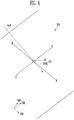
- FIGS. 1 and 2 illustrate a display device according to some example embodiments of the present invention.
- a display device DD1 may include an image display surface DP, a first photo sensor LS1, and a first camera CM1.
- the display device DD1 may include at least one processor PROC and memory MEM.
- the memory MEM may be a memory element for storing digital information or analog information.
- the processor PROC may be a dedicated purpose processor for implementing a specific algorithm, or may be a general purpose processor capable of implementing various algorithms.
- the display device DD1 may include or be connected to a memory, the memory storing instructions that, when executed by the processor PROC, cause the processor PROC to execute the functionality described herein.
- the processor PROC may be a single processor, or may include a plurality of processors. For example, an algorithm described later may be implemented by a general purpose processor or may be implemented as a plurality of dedicated purpose processors implementing each part of the algorithm.
- the algorithm may be implemented as a combination of a general purpose processor and a dedicated purpose processor.
- a general purpose processor for better understanding and ease of description, and a person which is an ordinary skill in the art may manufacture a dedicated purpose processor corresponding to each part of the algorithm.
- the image display surface DP may correspond to an emitting surface of the pixels PXs. Each of the pixels PXs may emit light based on the corresponding grayscale value. The image display surface DP may display an image frame through a combination of the pixels PXs emitting light.
- the pixels PXs may be included in a light emitting diode display panel, a liquid crystal display panel, or the like.
- each pixel may include at least one organic light emitting diode or inorganic light emitting diode.
- each pixel may include at least one quantum dot light emitting element.
- the display device DD1 can display an image frame because the light emitting diodes themselves emit light.
- the pixels in a liquid crystal display panel may adjust transmittance of light emitted from a backlight unit so that the display device DD1 can display the image frame.
- the transmittance of light can be controlled by a size and direction of an electric field applied to a liquid crystal layer corresponding to each pixel.
- a protective film or window may also be attached on the liquid crystal display panel.
- the image display surface DP may be partitioned into arbitrarily-sized regions.
- Each region may include at least one pixel.
- a size of each region may correspond to each pixel.
- the size of each region may be preset or may be set by the user after shipment or by an update of a manufacturer.
- an arbitrary pixel is assumed to be a first region ar1.
- an emitting area of the corresponding pixel may correspond to the first region ar1.
- an external light source OL may emit an external light ray 1 having an incident angle agi (e.g., relative to the surface of the display device DD1 or a direction normal to the surface of the display device DD1) with respect to the first region ar1.
- the external light source OL may include the sun, external lighting, interior room lighting, and the like.
- the processor PROC may determine the incident angle agi of the external light source OL with respect to the first region ar1 by using the first photo sensor LS1.
- the configuration of the first photo sensor LS1 according to some example embodiments of the present invention will be described in more detail with reference to FIGS. 2 to 5 .
- the processor PROC can determine intensity as well as the incident angle agi of the external light source OL by using the first photo sensor LS1.
- the processor PROC may determine a reflection angle agr of a user's eyeball PP (e.g., relative to a display surface of the display device DD1 or a direction normal to the the display surface of the display device DD1) with respect to the first region ar1 by using the first camera CM1.
- the first camera CM1 may include any suitable camera. A determination process of the reflection angle agr using the first camera CM1 will be described in more detail with reference to FIGS. 6 to 10 .
- the processor PROC can raise the luminance of the first region ar1.
- the processor RPOC locally raises the luminance level of at the first region ar1, so that the user can more easily recognize the image displayed in the first region ar1 despite the reflection light rray1.
- the processor PROC may locally raise the luminance of the peripheral region RL by repeating the above-described process for the peripheral region RL of the first region ar1.
- the processor RPOC may locally raise the luminance level without performing the above-described process (e.g., immediately) for the peripheral region RL within the range (e.g., the predetermined range) from the first region ar1 when locally raising the luminance of the first region ar1.
- the image display surface DP is located on a plane extending in a first direction DR1 and a second direction DR2, which are orthogonal to each other. It is assumed that a third direction DR3 is a direction orthogonal to the first direction DR1 and the second direction DR2 and is a direction vertical to the image display surface DP.
- the incidence angle agi and the reflection angle agr described above refer to an angle with respect to an axis of the third direction DR3 in the first region ar1.
- the above-described assumption is for accurate positional description, so the image display surface DP may not be planar when the display panel is flexible.
- FIGS. 3 to 6 drawings are for a photo sensor according to some example embodiments of the present invention.
- the first photo sensor LS1 may include a substrate SUB1, photo sensor units PD1, PD2, PDc, PDt, and the like, and a cover CV.
- FIG. 3 is a drawing for illustrating the substrate SUB1
- FIG. 4 is a drawing for illustrating a case where the cover CV is positioned on the substrate SUB1 of FIG. 3
- FIG. 5 is a cross-sectional view taken along a line A-A' of FIGS. 3 and 4
- FIG. 6 is a cross-sectional view taken along a line B-B' of FIGS. 3 and 4 .
- the substrate SUB1 includes a concave surface CVP.
- the concave surface CVP may be a hemisphere shape.
- the substrate SUB1 may be made of hard material such as glass, plastic, metal. If the concave surface CVP can support the photo sensor units PD1, PD2, PDc, PDt, and the like, the material of the substrate SUB1 is not limited.
- the photo sensor units PD1, PD2, PDc, PDt, and the like may be arranged on the concave surface CVP.
- the photo sensor units PD1, PD2, PDc, PDt, and the like may be formed of a photo diode, a photo transistor, a photo conductive cell, a photo coupler, a photo interrupter, a thermopile, a bolometer, a photoelectric tube, and the like.
- the cover CV may cover the concave surface CVP, may be spaced apart from the photo sensor units PD1, PD2, PDc, PDt, and the like, and may include a transmissive region and a non-transmissive region.
- the cover CV may include the second substrate SUB2.
- the second substrate SUB2 may be formed of an opaque material.
- the transmissive region may correspond to an opening CO of the second substrate SUB2.
- the non-transmissive region may refer to a remaining region except for the opening CO in the second substrate SUB2.
- the transmissive region may be formed of a transparent material (e.g., glass, plastic, metal, etc.) rather than an opening in the second substrate SUB2.
- the second substrate SUB2 may be formed of a transparent material, and an opaque film or the like may be attached to the non-transmissive region.
- the transmissive region corresponds the opening CO
- the non-transmissive region corresponds the substrate SUB2 except for the opening CO.
- the transmissive region may be positioned corresponding to a center of the hemisphere shape.
- the center of the hemisphere shape may refer to a specific position with the same distance to any positions on a hemisphere surface.
- the distances from the transmission region to the photo sensor units PD1, PD2, PDc, PDt, and the like may be equal to each other.
- the processor PROC may determine a target photo sensor unit PDt that generates the largest signal (e.g., a current signal or a voltage signal) for the external light source OL of the photo sensor units PD1, PD2, PDc, PDt, and the like.
- the processor PROC can determine the incident angle of the external light ray2 using the relative position to the target photo sensor unit PDt from the opening CO.
- the processor PROC may determine the three-dimensional position of the target photo sensor unit PDt using a spherical coordinate system with the opening CO as its origin.
- the processor PROC may determine the three-dimensional position of the photo sensor unit PDt with respect to the opening CO using a Cartesian coordinate system with respect to an arbitrary origin.
- angles of the external rays ray1 and ray2 and the reflection light rray1 are defined in a first plane based on the first direction DR1 and the third direction DR3
- angles of the external rays ray1 and ray2 and the reflection light rray1 are defined in a second plane based on the second direction DR2 and the third direction DR3.
- FIG. 5 shows the incidence angle agi11 of the external light ray2 with respect to an optical axis CAXs1 in the first plane
- FIG. 6 shows the incident angle agi12 of the external light ray2 with respect to the optical axis CAXs1 in the second plane
- the optical axis CAXs1 is defined as an axis passing through the center of the opening CO in the third direction DR3.
- the above-described angular representation method does not limit the method of determining the angles of the external lights ray1 and ray2 and the reflection light rray1, and explains that the angles of the external light ray1 and ray2 and the reflection light rray1 may be expressed in various aspects.
- the processor PROC may determine the incident angle agi of the external light ray1 with respect to the first region ar1 of the image display surface DP using the first photo sensor LS1. For example, the processor PROC may determine the incident angle of the external light ray2 with respect to the first photo sensor LS1 as the incident angle agi of the external light ray1 with respect to the first region ar1.
- the incidence angles of the external lights ray1 and ray2 are shown to be different from each other due to the limitation of a paper in FIG. 1 , but the incident angles of the external rays ray1 and ray2 may be substantially the same when the external light source OL is far enough away from the display device DD1.
- FIGS. 7 to 11 illustrate a process for determining a position of the eye of a user.
- the processor PROC may determine the reflection angle agr of the user's eyeball PP with respect to the first region ar1 by correcting the reflection angle agr of the user's eyeball PP with respect to the camera CM1 using the relative distances (-) ref1 and (+) ref2 of the first region ar1 with respect to the first camera CM1.
- FIGS. 7 and 8 a method for determining the reflection angle agr of the user's eyeball PP with respect to the first camera CM1 will be described.
- the reflection angle agr11 of the user's eyeball PP with respect to the first camera CM1 in the first plane is shown
- the reflection angle agr12 of the user's eyeball PP with respect to the first camera CM1 in the second plane is shown.
- a focal length f1 from a first camera origin O1 to a first image plane IMP1 of the first camera CM1 may be a fixed parameter value of the first camera CM1.
- the optical axis CAXc1 of the first camera CM1 may pass through the first image plane IMP1 from the first camera origin O1 in the third direction DR3.
- the processor PROC may search for a point P1 where the image of the user's eyeball PP is located in the first image plane IMP1. Once the point P1 is determined, the processor PROC may measure a distance d11 from an intersection of the optical axis CAXc1 and the first image plane IMP1 to the point P1 in the first direction DR1. Therefore, the processor PROC may determine the reflection angle agr11 of the user's eyeball PP with respect to the first camera CM1 in the first plane using feature of a right-angled triangle.
- the height Z1 may be set before shipment or may be set after shipment.
- the height Z1 may be calibrated by the user. If the height Z1 is determined, the distance dd11 from the first camera origin O1 or the first camera CM1 to the user's eyeball PP in the first direction DR1 can be determined using the feature of the right-angled triangle. Hereinafter, it is assumed that the height Z1 is determined to be a specific value.
- the processor PROC can measure a distance d12 from the intersection of the optical axis CAXc1 and the first image plane IMP1 to the point P1 in the second direction DR2. Therefore, the processor PROC determines the reflection angle agr12 of the user's eyeball PP with respect to the first camera CM1 in the second plane using the features of the right-angled triangle.
- the distance dd12 from the first camera origin O1 or first camera CM1 to the user's eyeball PP in the second direction DR2 using the feature of the right-angled triangle may be measured.
- the axis axDR2 may pass through the first camera CM1 and extend in the first direction DR1.
- the axis axDR1 may pass through the first camera CM1 and extend in the second direction DR2.
- the first region ar1 may be located at a first distance (-) ref1 from the first camera CM1 in the opposite direction of the first direction DR1 and at a second distance (+) ref2 in the second direction DR2.
- each region with respect to the first camera CM1 may be created in the form of a look-up table LUT before shipment and stored in the memory MEM.
- the processor PROC may calculate the distance dd11' from the first region ar1 to the user's eyeball PP in the first direction DR1 by calculating the difference between the distance dd11 and the first distance (-) ref1.
- the processor PROC may determine the reflection angle agr11' of the user's eyeball PP with respect to the first region ar1 in the first plane using the feature of the right-angled triangle.
- the processor PROC can calculate the distance dd12' from the first region ar1 to the user's eyeball PP in the second direction DR2 by calculating the difference between distance dd12 and second distance (+) ref2.
- the processor PROC can determine the reflection angle agr12' of the user's eyeball PP with respect to the first region ar1 in the second plane using the feature of the right-angled triangle.
- the reflection angle agr11' in the first plane and the reflection angle agr12' in the second plane may be defined.
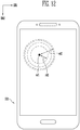
- FIG. 12 is a drawing for illustrating a case increasing locally luminance of a first region of an image display surface.
- the processor PROC may raise luminance of the first region ar1 when the incident angle agi and the reflection angle agr correspond to each other. As described above, when the incident angle agi with respect to the first region ar1 from the external light source OL corresponds to the reflection angle agr of the user's eyeball PP with respect to the first region ar1, it may be difficult for the user to visually recognize an image displayed in the first region ar1 by the reflection light rray1.
- the processor RPOC locally raises the luminance of the first region ar1, so that the user can more easily recognize the image displayed in the first region ar1 despite the reflection light rray1.
- the processor PROC may locally raise the luminance of the peripheral region located at a predetermined distance rd1 from the first region ar1. At this time, an increase amount of the luminance in the peripheral region may be the same as an increase amount of the luminance in the first region ar1.
- the processor PROC may locally raise the luminance of the peripheral region located at a predetermined distance rd2 from the first region ar1. At this time, as the distance from the first region ar1 increases, the increase amount of the luminance in the peripheral region may be reduced.
- the luminance difference between the first region ar1 where the luminance is raised and the peripheral region where the luminance is maintained e.g., the peripheral region farther than the distance rd2
- the luminance difference between the first region ar1 where the luminance is raised and the peripheral region where the luminance is maintained e.g., the peripheral region farther than the distance rd2
- FIGS. 13 and 14 are drawings for illustrating a process of calibrating a height of the user's eyeball to the display device.
- the processor PROC may calibrate the height Z1' of the user's eyeball with respect to the display device DD1.
- the processor PROC may initiate a request that the user to position the user's eyeball PPe1 on a first measurement region are1.
- the processor PROC may initiate display of an image (e.g., blinking, different color, higher luminance, etc.) that emphasizes the first measurement region are1 of the image display surface DP and request the user to position the user's eyeball PPe1 in the third direction DR3 from the first measurement region are1.
- the request can be performed with sound, image display, and the like.
- the user can inform the processor PROC that the user's eyeball PPe1 is located on the first measurement region are1 by pressing the completion button or using voice recognition function.
- the processor PROC can measure a first angle agr121 of the user's eyeball PPe1 with respect to the first camera CM1. Refer to description of FIGS. 7 and 8 for the angle measurement method.
- the processor PROC may request that the user's eyeball PPe2 is located on the second measurement region are2 of the display device DD1 while maintaining the height Z1' of the user's eyeball PPe2 with respect to the display device DD1.
- the processor PROC can measure the second angle agr122 of the user's eyeball PPe2 with respect to the first camera CM1.
- the processor PROC may determine the height Z1' of the user's eyeball PPe1 with respect to the display device DD1 based on the first angle agr121, the second angle agr122 and a distance dPP between the first measurement region are1 and the second measurement region are2.
- An angle agd1 is a difference value between 90 degrees and the angle agr121.
- An angle agd2 is a difference value between 180 degrees and the angle agd1.
- An angle agd3 is a difference value between the angles agr122 and the angle agr121.
- An angle agd4 is a value left by subtracting the angles agd2 and agd3 from 180 degrees.
- the distance dPP' is the same as the distance dPP.
- the processor PROC can calculate the height Z1'.
- the processor PROC can use the determined height Z1' of the user's eyeball PP in the process of determining the reflection angle agr of the user's eyeball PP. For example, the processor PROC may replace the height Z1 with the height Z1' in the process of FIG. 7 to 11 .
- only one first camera CM1 may be enabled to determine the reflection angle agr of the user's eyeball PP.
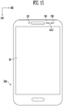
- FIGS. 15 and 16 are drawings of a process of determining a three-dimensional position of the user's eye using two cameras.
- the display device DD2 may further include the second camera CM2 as compared to the display device DD1 of FIG. 1 .
- the second camera CM2 may be spaced apart from the first camera CM1 by a distance do12.
- FIG. 16 a process of calculating the height Z1 of the user's eyeball PP using triangulation is shown.
- the first camera CM1 can calculate the angle agr11 using a focal distance f1 and a distance d11.
- the focal distance f1 is a distance from the first camera origin O1 to the first image plane IMP1.
- the distance d11 refers to an interval from the intersection of an axis CAXc1 and the first image plane IMP1 to the point P1 at which the image of the user's eyeball PP is formed on the first image plane IMP1.
- the second camera CM2 can calculate the angle agr21 using a focal distance f2 and a distance d21.
- the focal distance f2 is a distance from the second camera origin O2 to the second image plane IMP2.
- the distance d21 refers to an interval from the intersection of an axis CAXc2 to the second image plane IMP2 to the point P2 at which the image of the user's eyeball PP is formed on the second image plane IMP2.
- the angle agr11r corresponds to the difference between the angle 90 and the angle agr11
- the angle agr21r corresponds to the difference between the angle 90 and the angle agr21.
- a distance between the first camera origin O1 and the second camera origin O2, that is, a distance do12 corresponding to a length of a base line is a predetermined value.
- the processor PROC can calculate the height Z1.
- a calibration process may be omitted and the height Z1 of the user's eyeball PP can be measured in real time.
- a person of an ordinary skill in the art may obtain the height Z1 of the user's eyeball PP using other methods of stereo vision. For example, there is a method using epipolar geometry.
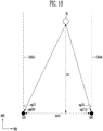
- FIGS. 17 and 18 are drawings for illustrating an a process of determining a three-dimensional position of an external light source using two photo sensors.
- the display device DD3 may further include a second photo sensor LS2 unlike the display device DD1 of FIG. 1 .
- the second photo sensor LS2 may be spaced apart from the first photo sensor LS1 by a distance ds12.
- the configuration of the second photo sensor LS2 may be substantially the same as that of the first photo sensor LS1, some duplicate descriptions thereof will be omitted.
- the processor PROC can determine the three-dimensional position of the external light source OL with respect to the display device DD3 using the first photo sensor LS1 and the second photo sensor LS2.
- the processor PROC may obtain the incident angle agi21 of the external light with respect to the first photo sensor LS1 from the external light source OL. Similarly, the processor PROC may obtain the incident angle agi11 of the external light with respect to the second photo sensor LS2 from the external light source OL.
- the incident angle agi11 is based on the optical axis CAXs1 of the first photo sensor LS1 and the incident angle agi21 is based on the optical axis CAX2 of the second photo sensor LS2.
- the angle agi21r corresponds to the difference of 90 degrees and the incidence angle agi21
- the angle agi11 r corresponds to the difference of 90 degrees and the incidence angle agi11.
- the distance ds12 may be a predetermined value.
- the processor PROC can calculate the height Z2 of the external light source OL.
- the height Z2 or the three-dimensional position of the external light source OL may be specified in real time when the external light source OL is not located far enough away from the display device DD3.
- the processor PROC can determine the incident angle of the external light with respect to the first region ar1 using the three-dimensional position of the external light source OL. Referring to FIGS. 9 to 11 , by correcting the reflection angles agr11 and agr12 of the user's eyeball PP with respect to the first camera CM1 with the relative distances (-) ref1 and (+) ref2 of the first region ar1 with respect to the first camera CM1, the process of determining the reflection angles agr11' and agr12' of the user's eyeball PP with respect to the first region ar1 has been described.
- the incident angle of the external light source OL with respect to the first region ar1 can be determined.
- embodiments of the present invention may more accurately calculate the incidence angle with respect to the first region ar1.
- the electronic or electric devices and/or any other relevant devices or components according to embodiments of the present invention described herein may be implemented utilizing any suitable hardware, firmware (e.g. an application-specific integrated circuit), software, or a combination of software, firmware, and hardware.
- the various components of these devices may be formed on one integrated circuit (IC) chip or on separate IC chips.
- the various components of these devices may be implemented on a flexible printed circuit film, a tape carrier package (TCP), a printed circuit board (PCB), or formed on one substrate.
- the various components of these devices may be a process or thread, running on one or more processors, in one or more computing devices, executing computer program instructions and interacting with other system components for performing the various functionalities described herein.
- the computer program instructions are stored in a memory which may be implemented in a computing device using a standard memory device, such as, for example, a random access memory (RAM).
- the computer program instructions may also be stored in other non-transitory computer readable media such as, for example, a CD-ROM, flash drive, or the like.
- a person of skill in the art should recognize that the functionality of various computing devices may be combined or integrated into a single computing device, or the functionality of a particular computing device may be distributed across one or more other computing devices without departing from the scope of the claims
Landscapes
- Engineering & Computer Science (AREA)
- Physics & Mathematics (AREA)
- General Physics & Mathematics (AREA)
- Theoretical Computer Science (AREA)
- Computer Hardware Design (AREA)
- Spectroscopy & Molecular Physics (AREA)
- General Engineering & Computer Science (AREA)
- Chemical & Material Sciences (AREA)
- Crystallography & Structural Chemistry (AREA)
- Human Computer Interaction (AREA)
- Computer Vision & Pattern Recognition (AREA)
- Signal Processing (AREA)
- Sustainable Development (AREA)
- Multimedia (AREA)
- Life Sciences & Earth Sciences (AREA)
- Position Input By Displaying (AREA)
- Control Of Indicators Other Than Cathode Ray Tubes (AREA)
- Devices For Indicating Variable Information By Combining Individual Elements (AREA)
- Light Receiving Elements (AREA)
- Photometry And Measurement Of Optical Pulse Characteristics (AREA)
- Controls And Circuits For Display Device (AREA)
- User Interface Of Digital Computer (AREA)
- Solid State Image Pick-Up Elements (AREA)
Applications Claiming Priority (1)
| Application Number | Priority Date | Filing Date | Title |
|---|---|---|---|
| KR1020190002921A KR20200086786A (ko) | 2019-01-09 | 2019-01-09 | 광 센서, 이를 포함하는 표시 장치, 및 표시 장치의 구동 방법 |
Publications (2)
| Publication Number | Publication Date |
|---|---|
| EP3680884A2 true EP3680884A2 (de) | 2020-07-15 |
| EP3680884A3 EP3680884A3 (de) | 2020-07-22 |
Family
ID=69182466
Family Applications (1)
| Application Number | Title | Priority Date | Filing Date |
|---|---|---|---|
| EP20151011.2A Withdrawn EP3680884A3 (de) | 2019-01-09 | 2020-01-09 | Fotosensor, anzeigevorrichtung damit und ansteuerverfahren dafür |
Country Status (5)
| Country | Link |
|---|---|
| US (1) | US10923078B2 (de) |
| EP (1) | EP3680884A3 (de) |
| JP (1) | JP2020112554A (de) |
| KR (1) | KR20200086786A (de) |
| CN (1) | CN111486948B (de) |
Families Citing this family (1)
| Publication number | Priority date | Publication date | Assignee | Title |
|---|---|---|---|---|
| CN116453485A (zh) * | 2023-04-07 | 2023-07-18 | Oppo广东移动通信有限公司 | 屏幕亮度调节方法、装置、电子设备和存储介质、产品 |
Citations (2)
| Publication number | Priority date | Publication date | Assignee | Title |
|---|---|---|---|---|
| US20030098954A1 (en) * | 2001-04-27 | 2003-05-29 | International Business Machines Corporation | Calibration-free eye gaze tracking |
| EP2823751A1 (de) * | 2013-07-09 | 2015-01-14 | Smart Eye AB | Blickabbildung des Auges |
Family Cites Families (11)
| Publication number | Priority date | Publication date | Assignee | Title |
|---|---|---|---|---|
| US5854661A (en) * | 1997-09-30 | 1998-12-29 | Lucent Technologies Inc. | System and method for subtracting reflection images from a display screen |
| US6853445B2 (en) * | 2002-01-07 | 2005-02-08 | Motorola, Inc. | Two-dimensional angle of arrival detection device |
| US20120229487A1 (en) * | 2011-03-11 | 2012-09-13 | Nokia Corporation | Method and Apparatus for Reflection Compensation |
| US9582083B2 (en) | 2011-12-22 | 2017-02-28 | Apple Inc. | Directional light sensors |
| US9557813B2 (en) * | 2013-06-28 | 2017-01-31 | Tactus Technology, Inc. | Method for reducing perceived optical distortion |
| KR101471612B1 (ko) * | 2013-07-01 | 2014-12-12 | 남부대학교산학협력단 | 광학렌즈 기반 태양위치 추적정밀도 측정시스템 |
| CN105765558A (zh) * | 2013-09-03 | 2016-07-13 | 醒眸行有限公司 | 低功率眼睛跟踪系统和方法 |
| KR101907143B1 (ko) | 2013-11-22 | 2018-10-12 | 한국과학기술연구원 | 성능이 우수한 반사방지막의 제조방법 및 그에 의하여 제조된 반사방지막 |
| KR102142624B1 (ko) * | 2013-12-30 | 2020-08-10 | 삼성디스플레이 주식회사 | 표시장치 |
| WO2015161495A1 (en) * | 2014-04-25 | 2015-10-29 | Telefonaktiebolaget L M Ericsson (Publ) | Adjusting brightness of display |
| KR20170060353A (ko) * | 2015-11-24 | 2017-06-01 | 삼성전자주식회사 | 전자 장치, 거리 측정 센서 및 그 제어 방법 |
-
2019
- 2019-01-09 KR KR1020190002921A patent/KR20200086786A/ko not_active Ceased
- 2019-08-16 US US16/543,297 patent/US10923078B2/en active Active
- 2019-12-19 CN CN201911317380.0A patent/CN111486948B/zh active Active
-
2020
- 2020-01-06 JP JP2020000335A patent/JP2020112554A/ja active Pending
- 2020-01-09 EP EP20151011.2A patent/EP3680884A3/de not_active Withdrawn
Patent Citations (2)
| Publication number | Priority date | Publication date | Assignee | Title |
|---|---|---|---|---|
| US20030098954A1 (en) * | 2001-04-27 | 2003-05-29 | International Business Machines Corporation | Calibration-free eye gaze tracking |
| EP2823751A1 (de) * | 2013-07-09 | 2015-01-14 | Smart Eye AB | Blickabbildung des Auges |
Also Published As
| Publication number | Publication date |
|---|---|
| US20200219462A1 (en) | 2020-07-09 |
| KR20200086786A (ko) | 2020-07-20 |
| JP2020112554A (ja) | 2020-07-27 |
| US10923078B2 (en) | 2021-02-16 |
| EP3680884A3 (de) | 2020-07-22 |
| CN111486948A (zh) | 2020-08-04 |
| CN111486948B (zh) | 2024-04-12 |
Similar Documents
| Publication | Publication Date | Title |
|---|---|---|
| KR102142624B1 (ko) | 표시장치 | |
| US9910282B2 (en) | Increasing field of view of head-mounted display using a mirror | |
| US20190204911A1 (en) | Eye tracking device and eye tracking method applied to video glasses and video glasses | |
| CN108398788B (zh) | 眼睛跟踪装置及虚拟现实成像设备 | |
| WO2017125984A1 (ja) | 空中表示装置 | |
| US20160286626A1 (en) | Display apparatus and method for controlling region for luminance reduction | |
| US10303211B2 (en) | Two part cone display using flexible substrates | |
| US20220319364A1 (en) | Eyewear projector brightness control | |
| US20240302025A1 (en) | Light Source Module with Adaptive Illumination | |
| EP3680884A2 (de) | Fotosensor, anzeigevorrichtung damit und ansteuerverfahren dafür | |
| CN110927973A (zh) | 显示装置 | |
| WO2018092627A1 (ja) | プロジェクターシステム | |
| US20230077073A1 (en) | Augmented reality device and method for obtaining depth map by using depth sensor | |
| WO2021114502A1 (zh) | 投影仪及投影方法 | |
| US10511832B1 (en) | Calibration of virtual image system with extended nasal field of view | |
| WO2021022438A1 (zh) | 背光基板及其制造方法、和显示装置 | |
| CN205537597U (zh) | 一种目视光学仪器 | |
| US10786326B1 (en) | Surgical image pickup system | |
| US10952324B2 (en) | Spacer for surface mountable electronic components | |
| JP2018085553A (ja) | プロジェクターシステム | |
| US10511137B2 (en) | Laser module with a flattened structure on a mobile device for image measurement | |
| CN113597357A (zh) | 用于并行微图案化的微透镜阵列 | |
| CN114822245B (zh) | 电子设备 | |
| TWI683135B (zh) | 頭戴型顯示裝置及用於其之調整方法 | |
| CN111953875A (zh) | 深度检测组件及电子设备 |
Legal Events
| Date | Code | Title | Description |
|---|---|---|---|
| PUAI | Public reference made under article 153(3) epc to a published international application that has entered the european phase |
Free format text: ORIGINAL CODE: 0009012 |
|
| STAA | Information on the status of an ep patent application or granted ep patent |
Free format text: STATUS: THE APPLICATION HAS BEEN PUBLISHED |
|
| PUAL | Search report despatched |
Free format text: ORIGINAL CODE: 0009013 |
|
| AK | Designated contracting states |
Kind code of ref document: A2 Designated state(s): AL AT BE BG CH CY CZ DE DK EE ES FI FR GB GR HR HU IE IS IT LI LT LU LV MC MK MT NL NO PL PT RO RS SE SI SK SM TR |
|
| AX | Request for extension of the european patent |
Extension state: BA ME |
|
| AK | Designated contracting states |
Kind code of ref document: A3 Designated state(s): AL AT BE BG CH CY CZ DE DK EE ES FI FR GB GR HR HU IE IS IT LI LT LU LV MC MK MT NL NO PL PT RO RS SE SI SK SM TR |
|
| AX | Request for extension of the european patent |
Extension state: BA ME |
|
| RIC1 | Information provided on ipc code assigned before grant |
Ipc: G09G 3/20 20060101AFI20200617BHEP |
|
| STAA | Information on the status of an ep patent application or granted ep patent |
Free format text: STATUS: REQUEST FOR EXAMINATION WAS MADE |
|
| 17P | Request for examination filed |
Effective date: 20200916 |
|
| RBV | Designated contracting states (corrected) |
Designated state(s): AL AT BE BG CH CY CZ DE DK EE ES FI FR GB GR HR HU IE IS IT LI LT LU LV MC MK MT NL NO PL PT RO RS SE SI SK SM TR |
|
| STAA | Information on the status of an ep patent application or granted ep patent |
Free format text: STATUS: EXAMINATION IS IN PROGRESS |
|
| 17Q | First examination report despatched |
Effective date: 20210924 |
|
| STAA | Information on the status of an ep patent application or granted ep patent |
Free format text: STATUS: THE APPLICATION IS DEEMED TO BE WITHDRAWN |
|
| 18D | Application deemed to be withdrawn |
Effective date: 20220205 |