EP3680892A1 - Dispositif de support réglable pour un instrument de musique - Google Patents
Dispositif de support réglable pour un instrument de musique Download PDFInfo
- Publication number
- EP3680892A1 EP3680892A1 EP20150378.6A EP20150378A EP3680892A1 EP 3680892 A1 EP3680892 A1 EP 3680892A1 EP 20150378 A EP20150378 A EP 20150378A EP 3680892 A1 EP3680892 A1 EP 3680892A1
- Authority
- EP
- European Patent Office
- Prior art keywords
- cord
- insert
- recess
- cup
- groove
- Prior art date
- Legal status (The legal status is an assumption and is not a legal conclusion. Google has not performed a legal analysis and makes no representation as to the accuracy of the status listed.)
- Granted
Links
Images





Classifications
-
- G—PHYSICS
- G10—MUSICAL INSTRUMENTS; ACOUSTICS
- G10G—REPRESENTATION OF MUSIC; RECORDING MUSIC IN NOTATION FORM; ACCESSORIES FOR MUSIC OR MUSICAL INSTRUMENTS NOT OTHERWISE PROVIDED FOR, e.g. SUPPORTS
- G10G5/00—Supports for musical instruments
- G10G5/005—Supports for musical instruments while playing, e.g. cord, strap or harness
-
- A—HUMAN NECESSITIES
- A45—HAND OR TRAVELLING ARTICLES
- A45F—TRAVELLING OR CAMP EQUIPMENT: SACKS OR PACKS CARRIED ON THE BODY
- A45F5/00—Holders or carriers for hand articles; Holders or carriers for use while travelling or camping
-
- F—MECHANICAL ENGINEERING; LIGHTING; HEATING; WEAPONS; BLASTING
- F16—ENGINEERING ELEMENTS AND UNITS; GENERAL MEASURES FOR PRODUCING AND MAINTAINING EFFECTIVE FUNCTIONING OF MACHINES OR INSTALLATIONS; THERMAL INSULATION IN GENERAL
- F16G—BELTS, CABLES, OR ROPES, PREDOMINANTLY USED FOR DRIVING PURPOSES; CHAINS; FITTINGS PREDOMINANTLY USED THEREFOR
- F16G11/00—Means for fastening cables or ropes to one another or to other objects; Caps or sleeves for fixing on cables or ropes
- F16G11/10—Quick-acting fastenings; Clamps holding in one direction only
- F16G11/101—Quick-acting fastenings; Clamps holding in one direction only deforming the cable by moving a part of the fastener
-
- F—MECHANICAL ENGINEERING; LIGHTING; HEATING; WEAPONS; BLASTING
- F16—ENGINEERING ELEMENTS AND UNITS; GENERAL MEASURES FOR PRODUCING AND MAINTAINING EFFECTIVE FUNCTIONING OF MACHINES OR INSTALLATIONS; THERMAL INSULATION IN GENERAL
- F16G—BELTS, CABLES, OR ROPES, PREDOMINANTLY USED FOR DRIVING PURPOSES; CHAINS; FITTINGS PREDOMINANTLY USED THEREFOR
- F16G11/00—Means for fastening cables or ropes to one another or to other objects; Caps or sleeves for fixing on cables or ropes
- F16G11/14—Devices or coupling-pieces designed for easy formation of adjustable loops, e.g. choker hooks; Hooks or eyes with integral parts designed to facilitate quick attachment to cables or ropes at any point, e.g. by forming loops
-
- G—PHYSICS
- G10—MUSICAL INSTRUMENTS; ACOUSTICS
- G10D—STRINGED MUSICAL INSTRUMENTS; WIND MUSICAL INSTRUMENTS; ACCORDIONS OR CONCERTINAS; PERCUSSION MUSICAL INSTRUMENTS; AEOLIAN HARPS; SINGING-FLAME MUSICAL INSTRUMENTS; MUSICAL INSTRUMENTS NOT OTHERWISE PROVIDED FOR
- G10D9/00—Details of, or accessories for, wind musical instruments
-
- A—HUMAN NECESSITIES
- A45—HAND OR TRAVELLING ARTICLES
- A45F—TRAVELLING OR CAMP EQUIPMENT: SACKS OR PACKS CARRIED ON THE BODY
- A45F3/00—Travelling or camp articles; Sacks or packs carried on the body
- A45F3/14—Carrying-straps; Pack-carrying harnesses
- A45F2003/142—Carrying-straps
-
- A—HUMAN NECESSITIES
- A45—HAND OR TRAVELLING ARTICLES
- A45F—TRAVELLING OR CAMP EQUIPMENT: SACKS OR PACKS CARRIED ON THE BODY
- A45F5/00—Holders or carriers for hand articles; Holders or carriers for use while travelling or camping
- A45F2005/006—Holders or carriers for hand articles; Holders or carriers for use while travelling or camping comprising a suspension strap or lanyard
-
- Y—GENERAL TAGGING OF NEW TECHNOLOGICAL DEVELOPMENTS; GENERAL TAGGING OF CROSS-SECTIONAL TECHNOLOGIES SPANNING OVER SEVERAL SECTIONS OF THE IPC; TECHNICAL SUBJECTS COVERED BY FORMER USPC CROSS-REFERENCE ART COLLECTIONS [XRACs] AND DIGESTS
- Y10—TECHNICAL SUBJECTS COVERED BY FORMER USPC
- Y10S—TECHNICAL SUBJECTS COVERED BY FORMER USPC CROSS-REFERENCE ART COLLECTIONS [XRACs] AND DIGESTS
- Y10S224/00—Package and article carriers
- Y10S224/91—Carrier for musical instrument
Definitions
- the invention relates to a device for adjusting the length of a cord for carrying a musical instrument, in particular a saxophone, a bass clarinet, a bassoon or a similar wind instrument.
- a wind instrument such as a saxophone is often carried by a carrying device on the neck or shoulders due to its weight.
- a carrying device comprises a carrying strap, also called a carrying strap, which is placed around the neck or a carrying frame, which is placed on the shoulders, and a cord, which is attached on the one hand to the carrying strap or frame and on the other hand with a hook on the instrument.
- a support frame as mentioned is for example in CH 704201 disclosed.
- a strap or carrying frame with a cord enables a heavy instrument to be played over a longer period of time without the musician becoming too tired.
- a cord for such a carrying device is, for example, twisted twice on the hook, as for example in US 1,637,003 discloses, wherein the double loop leads over a slider.
- the slider can be moved up and down, which varies the length of the double loop and the height position of the instrument.
- the slide comprises a cuboid element which is placed together with a spring in a cup-shaped element.
- the cuboid and the cup-shaped element each contain an opening through which three sections of the cord can be passed, the three sections touching each other in the opening. At When the spring is relaxed, the openings only partially overlap, so that the sections of the cord are clamped in there.
- the slider is held between the thumb and finger, and to change the length of the cord, the thumb and finger are pressed together so that the cuboid element is pressed against the spring force into the cup-shaped element and the two openings overlap more.
- the cord sections in the opening have more play and the slider can be moved along the cord. If the thumb and fingers are relieved again, the opening narrows and the cord sections are pressed together in the reduced opening and the slide is thereby locked.
- Cords are round cords or flat cords. Round cords are twisted or twisted with a round cross-section. Flat cords are cords with an elongated cross-section like that of a ribbon.
- the device according to the invention for adjusting the length of a cord is designed to receive a double and single cord and to change the length of the cord thus guided.
- the single-guided cord can be attached to a carrying device for a musical instrument on the neck or shoulders, and the double-guided cord can be connected to a hook for the musical instrument.
- the device for adjusting the length of a cord or band has two parts, a cup-shaped first part and an insert as a second part, the two parts being slidable into one another and a spring being arranged between the two parts.
- the cup-shaped, first part has a bottom and a circumferential edge, a recess or an inlet opening for the passage of two cord pieces or two bands and at least two further openings for two cord pieces or two bands being arranged in its circumferential wall.
- One or more first openings of these at least two further openings are arranged next to said recess or input opening, and one or more further openings are arranged opposite the first or more openings in the peripheral edge.
- the second part of the device for adjusting the length of a cord or band is designed as an insert in the cup-shaped, first part and has a groove with a U-turn, which is formed by a peripheral edge of the insert part and a central part.
- the U-turn has a U or O shape.
- the circumferential edge of the insert has a recess which leads into the groove.
- the groove serves to receive at least one piece of cord, which can be guided through the recess into the groove, along the groove with the turn and again through the recess out of the groove.
- the cord piece thus guided forms the shape of the U-turn according to the groove.
- the stake also has at least one Channel for a piece of cord or for a band, each of which leads from an entrance next to the recess or the entrance opening to an exit opposite the entrance.
- the at least one channel each has elements for deflecting and inhibiting the movement of a cord and is completely separated from the groove with the U-turn. That is, the recess or entrance opening that leads to the groove with the U-turn is completely separated from the entrance to the at least one channel.
- the cup-shaped, first part has a bottom and a peripheral edge, with a recess for two cord pieces and four further openings for each cord piece being arranged in its peripheral edge.
- the first and second of these four further openings are on both sides of the recess, and the third and fourth openings are each located opposite the first and second openings in the peripheral edge.
- the second part of the device for length adjustment is designed as an insert in the cup-shaped, first part and has a groove with a U-turn, which is formed by a peripheral edge of the insert part and a middle part.
- the circumferential edge of the insert has a recess which leads into the groove.
- the groove serves to receive a piece of cord which can be guided through the recess into the groove, along the groove with the turn and again through the recess out of the groove.
- the cord piece thus guided forms the shape of a U-turn according to the groove.
- the insert also has two channels for cord pieces designed as guide grooves, which are arranged on the outside of its circumferential edge and on both sides of the recess.
- the guide grooves are arranged on both sides of the recess, that is to say laterally next to the recess, they each lead from an entrance next to the recess to an exit opposite the entrance.
- the two guide grooves also have elements for deflecting and inhibiting the movement of a cord.
- the two side guide grooves are completely separated from the groove with the U-turn. Ie the recess that is used for Groove with the U-turn leads is completely separated from the entrances to the lateral guide grooves.
- This version is suitable for the length adjustment of cords with a round and elongated cross-section.
- the insert has a recess in its central part for receiving the spring.
- the elements for inhibiting the movement of a cord through the guide grooves are formed by surfaces that are angled to one another.
- the surfaces angled to one another can meet at a tip or be connected to one another by a further surface.
- These elements deflect a cord in the guide groove in the manner of a simple zigzag and thus cause the cord to rub against the guide grooves, thereby inhibiting the movement of the cord. If the device is held with a musical instrument such that the cords hang vertically, as in use, the deflecting elements have the effect that the cords in the guide grooves are first moved laterally away from the vertical direction and then returned again.
- the elements for deflecting and inhibiting the movement of a cord through the guide grooves comprise projections in the cup-shaped, first part, which extend perpendicularly away from the inner bottom of the first part, and also recesses in use, which are in the peripheral edge thereof are arranged.
- the recesses in the insert are arranged in accordance with the position of the projections in the cup-shaped part, so that when the insert is inserted, the projections engage in the recesses, extend through the recesses and protrude into the guide grooves.
- the projections in the guide grooves thus result in a deflection of a cord in the guide groove, again in the manner of a simple zigzags, first at an angle from the vertical and then back again.
- the cup-shaped part has a pin in the middle for fixing the position and alignment of the spring.
- the pin is positioned according to the position of the recess in the insert, so that when the insert is inserted into the cup-shaped part, the pin is inserted into the recess in the insert.
- a first piece of the cord is inserted into the insert by placing the cord piece in the groove with the turn and leading the ends out of the insert through the recess.
- the ends are then attached to a hook that can be attached to an instrument, for example by passing the ends through an eyelet on the hook.
- the insert with the cord in the groove with a U-turn is then inserted into the cup-shaped, first part, in which a spring is placed.
- the insert part is placed so that the position of the recess with the cord pieces leading in and out coincides with the position of the recess in the cup-shaped first part and the cord pieces also pass through the recess in the first part.
- the inputs and outputs of the two lateral guide grooves in use also correspond to the four openings in the cup-shaped, first part. Then the two ends of the cord are inserted through the openings in the cup-shaped part and the inputs of the lateral guide grooves in the insert, through the guide grooves of the insert, through the outputs of the guide grooves and through the opposite openings in the cup-shaped part again out of the device for adjustment. Finally, the ends of the cord are attached to a neck strap or a carrying device for a musical instrument.
- the spring is positioned, for example, through the recess in the middle of the insert and the pin in the cup-shaped part.
- the two parts of the device are held together due to the positioning of the cord in the guide grooves and in the four openings of the cup-shaped part. Thanks to the spring force of the spring, the cord pieces are clamped between the inputs and outputs of the guide grooves in the insert and the edge of the openings in the cup-shaped part.
- the insert is pushed deeper into the cup-shaped part and the spring is compressed.
- the openings in the cup-shaped part thus exactly match the openings in the insert, so that the entrances to the guide grooves become larger and the cord pieces in the guide grooves are freely movable.
- the device can then be moved up or down (from the musician's point of view) and the length of the double-guided cord pieces, ie the cord pieces between the device and the hook on the musical instrument, can be increased or decreased.
- the pressure on the device is released, whereby the spring is relaxed and the insert is moved somewhat out of the cup-shaped part.
- the entrances and exits of the lateral guide grooves are reduced again by the fact that the entrances and exits in use no longer correspond exactly to the four openings in the cup-shaped part and are narrowed.
- the entrances and exits of the guide grooves for the simply guided cord are narrowed again by slightly lifting the insert part out of the cup-shaped part and pressing the cord pieces into the openings of the cup-shaped part at their edges. As a result, the cord pieces are clamped in the openings and held in position. The cord pieces are thus clamped and locked between the guide grooves and the edge of the four openings in the cup-shaped, first part. The length of the cord and the position of the musical instrument thus remain constant.
- the cup-shaped, first part has an entrance opening for the passage of two pieces of cord or two bands.
- the cup-shaped part has only two further openings.
- an opening is arranged next to the entrance opening for the purpose of passing two pieces of cord or two ribbons, and the second opening is arranged opposite the first opening on the peripheral edge of the cup-shaped part.
- the second part of the device ie the insert, has only one channel designed as a passage, which leads from an entrance next to the recess to an exit opposite the entrance.
- the passage has elements for deflecting and inhibiting the movement of cords or tapes.
- the groove with the U-turn is completely separated from the entrance of the channel. Ie the recess leading to the groove is separated from the entrance to the channel.
- This version is suitable for the length adjustment of a flat cord or ribbon.
- the elements for inhibiting the movement of a cord or band through the channel are formed by surfaces that are angled to one another.
- the surfaces angled to one another can meet at a tip or be connected to one another by a further surface.
- the angle between the surfaces is more than 90 °.
- the insert has a recess in its central part for receiving the spring.
- two bands are placed one above the other.
- the tapes are perforated near their free ends.
- the free ends of the two bands are then passed from the outside through the inlet opening in the cup-shaped, first part and placed so that the hole in the bands lies over a recess in the bottom of the outer, cup-shaped part.
- the insert with the middle part is inserted into the cup-shaped part, the middle part engaging with the spring through the hole in the bands and into the recess.
- the two parts are then placed one inside the other and pressed together with the spring.
- the position of the recess with the strips leading out then coincides with the position of the entrance opening in the cup-shaped, first part, so that the strips pass straight through the recess of the groove in the insert part and through the entrance opening in the cup-shaped part.
- the tapes protruding from the device are then attached to a hook that can be attached to a musical instrument, for example by passing the ends through an eyelet on the hook.
- the ends of the superimposed tapes are inserted through the first opening in the cup-shaped part and the entrance of the passage in the insert, through the passage of the insert, through the exit of the passage and through the opposite second opening in the cup-shaped part again from the device for length adjustment led out.
- the openings in the insert and in the cup-shaped part are elongated and adapted to the cross section of a band.
- the ends of the straps are attached to a neck strap or a carrying device for a musical instrument.
- the two parts of the device are held together due to the positioning of the bands in the passage and in the two openings of the cup-shaped part. Thanks to the spring force of the spring, the strips are clamped between the entrance and exit of the passage in the insert and the edge of the openings in the cup-shaped part.
- the insert is pushed deeper into the cup-shaped part and the spring is compressed.
- the openings in the cup-shaped part thus correspond exactly to the openings in the insert, so that the access to the passage becomes larger and the belts can move freely in the passage.
- the device can then be moved up or down (from the musician's point of view) and the length of the double-guided tapes, ie the tapes between the device and the hook on the musical instrument, can be increased or decreased.
- the pressure on the device is released, whereby the spring is relaxed and the insert is moved somewhat out of the cup-shaped part.
- the entrances to the passage are reduced again in that the entrances and exits of the passage no longer match exactly with the two openings in the cup-shaped part and are narrowed.
- the entrances and exits of the guide grooves for the simply guided cord are narrowed again by slightly lifting the insert part out of the cup-shaped part and pressing the cord pieces into the openings of the cup-shaped part at their edges. This will clamp the straps in the openings and hold them in place.
- the strips are thus clamped and locked between the guide grooves and the edge of the two openings in the cup-shaped, first part.
- the length of the tapes and the position of the musical instrument remain constant.
- the device according to the invention has the advantage over those of the prior art, in particular US 1,637,003 that the side guide grooves in the insert are completely separated from the groove with the twist.
- the cord piece that runs along a U-turn to guide the cord in the central groove twice does not come into contact with the cord pieces in the side guide grooves of the insert.
- the cord pieces in the several grooves run in an orderly manner, remain unaffected by one another and always remain the same in their directional orientation.
- This enables the The device according to the invention for the musician always remains oriented in the same way and twisting of the device and the cord is avoided.
- the adjustment of the cord length requires less effort than with a device according to US 1,637,003 .
- the use of the device is thereby facilitated and allows for increased rest when making music.
- the separation of the guidance of the cord piece in the groove with the U-turn and the guidance of the cord pieces in the guide grooves of the insert brings about stability with respect to the rotation of the device. Thanks to the separation of the cord pieces, the device remains in the same position in that the bottom surface of the cup-shaped part is always in the same plane. The musician can thus grip the device more easily and reliably.
- the use of the device is simplified and quieter. While playing the musical instrument, the cord is stretched by the weight of the instrument.
- the elements for deflecting and inhibiting the movement of the cord in the guide grooves by friction allow the stability of the length of the cord set in each case.
- the spring-loaded clamping of the cord between the insert and the cup-shaped part of the device ensures the stability of the length of the cord set in each case.
- the device makes it possible that the cord length cannot be adjusted independently, even when the cord is not tensioned.
- the cord pieces are held in place by the elements for deflecting and inhibiting the movement of the cord pieces and by narrowing the inputs and outputs of the guide grooves. This means that the cord does not come loose on its own when making music. An unwanted extension cannot occur. Thanks to the separation of the cord pieces by the mutually independent guide grooves, the cord remains intact longer and after frequent length adjustment because the cord pieces do not touch and do not rub against each other. The device according to the invention can thus remain in use longer. Jags, barbs or the like in the guide to hold the cord by means of Friction is not necessary. An early fraying of the cord can be avoided.
- the device according to the invention is suitable for use with various types of carrying devices for musical instruments, including carrying devices with a carrying strap (carrying strap) around the neck as well as carrying devices with a carrying frame which is carried on the shoulders to which the cord pieces can be attached.
- the device is particularly suitable for wind instruments such as saxophone, bass clarinet and bassoon.
- a carrying device for carrying a musical instrument with a carrying strap for the neck or a carrying frame for shoulders, a cord or a band, an attachment of the cord to the musical instrument, the carrying device having a device according to the invention for adjusting the length of the cord as described.
- One embodiment of the carrying device has a hook with an eyelet for attaching the cord to the musical instrument.
- the cord 4 leads into a device 3 according to the invention for adjusting the length of the cord 4, the cord 4 leading out again at the lower end of the device 3 and being guided in a double loop through the eye of a hook 5.
- the hook 5 can be hooked onto the musical instrument M and fastened
- Figure 3 shows the carrying device 1 somewhat enlarged and in particular two parts of the device 3, an outer first part 10 and an inner second part 20.
- Simply guided cord pieces 4 lead from the carrying strap 2 through openings in the parts 10 and 20 at the upper end of the device 3 inside.
- Double-guided cord pieces 4 lead through further openings in parts 10 and 20 at the lower end of device 3 to eyelet 5 'of hook 5.
- Figure 4 shows a cup-shaped, first part 10 of the inventive device from the Figures 1-3 , which is round in the embodiment shown and has a round bottom 11 with a peripheral edge 12. At one point of the peripheral edge 12 there is a recess 13 for receiving a double-guided cord piece, which is used by a groove with a U-turn, as in FIG Figure 5a shown, can be performed.
- Two openings 14 are arranged on both sides of the recess 13, through which a further piece of cord can be passed.
- two further openings 15 are arranged in the peripheral edge 12, through which the said cord pieces can be led out of the device according to the invention.
- a pin 16 is arranged in the center inside the cup-shaped part 10 and serves to position a spiral spring.
- Figures 5a and b show an insert 20 made in the cup-shaped part Figure 4 can be used.
- the shape of the insert 20 is adapted to the cup shape of the first part 10 and has an upper surface 21 and a peripheral surface Area 22 on.
- a recess 23 is arranged on the peripheral surface 22. If the insert 20 is inserted into the first part 10, the insert 20 is enclosed by the peripheral edge 12 and the recesses 13 and 23 of the two parts 10 and 20 correspond in their position.
- the insert 20 has a groove 24 which extends away from the recess 23 and forms a U-shaped U-turn or another similar turn, the turn being approximately 180 °. In the middle of the insert 20, enclosed by the groove 24, there is a central part 25 with a recess into which a spring 26 can be placed.
- the insert 20 When insert 20 is inserted into cup-shaped part 10, pin 16 engages in the recess and in spring 26.
- the insert 20 also has two lateral guide grooves 28 in the circumferential surface 22 in a symmetrical arrangement, which start on both sides of the recess 23 and extend around part of the insert 20 along the surface 22, the ends of which preferably lie opposite the recess 23 Side of the insert 20.
- the guide grooves 28 serve to guide cord pieces. According to the invention, they have elements for deflecting and inhibiting the movement of cords. In the embodiment shown, these elements are in the form of beveled surfaces 29 which lead towards one another and meet at a tip 29 '.
- the composition of the two parts 10 and 20 is shown, the device 3 being shown cut away.
- Figure 6a and c also shows the arrangement of cord pieces in the device 3 according to the invention.
- a cord piece 4a is inserted into the insert 20, in particular into the groove 24 with the U-turn and around the middle part 25.
- the two ends of the cord piece 4a then lead through the recess 23 of the insert 20 and the recess 13 of the cup-shaped part 10 out of the device 3 and are laced through the eyelet 5 'of the hook 5.
- the two cord pieces, now designated 4b lead back to the device 3 and through the openings 14 of the cup-shaped part 10 and along the guide grooves 28 of the insert 20.
- cord pieces 4b lead then on the opposite side out of the guide grooves 28 of the insert 20 and out of the device 3 through the openings 15 of the cup-shaped part 10. Then the cord pieces, now designated 4c, lead to a carrying strap or a carrying frame as in Figure 1-3 shown.
- the cord pieces are guided along the two mutually running surfaces 29 and around the surface 29 ′ which connects the surfaces 29, the cord pieces on the outer side of the groove 28 from the inner surface of the peripheral edge 12 of the cup-shaped part 10 are led.
- the peculiarity of the invention is the separate guidance of the cord pieces 4a and 4b, in that they lead through separate openings or recesses 13, 14 and 23 and the cord piece in the groove 24 does not touch the cord pieces in the lateral grooves 28 with a U-turn. If the length of the cord is changed, the length of the cord pieces 4a and 4b is changed, ie the length of the double cord is lengthened or shortened. The length of the simply guided piece 4c also changes accordingly. With a length adjustment, however, the part of the cord that is in the groove 24 with a U-turn always remains in place. Only the parts of the cord that pass through the guide grooves 28 move.
- the device 3 can be moved along the cord pieces in the guide grooves 28 when the insert 20 is pressed into the cup-shaped part 10 against the force of the spring 26, so that the openings 14 and 15 correspond most closely to the inputs and outputs of the guide grooves 28 .
- the device 3 can then be moved up or down or the cord length shortened or lengthened. If the pressure on the insert 20 and on the spring 26 is relieved, the spring relaxes and the insert 20 again moves somewhat out of the cup-shaped part 10. The entrances and exits of the guide grooves 28 narrow and the cord pieces are firmly clamped between the two parts 10 and 20.
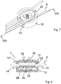
- Figure 8 shows the device 3 in a section according to VIII-VIII in Figure 7 and illustrates the mechanism of clamping the cord pieces in the device 3 when the spring 26 is relaxed.
- the insert 20 is somewhat removed from the spring 26 cup-shaped part 10 pushed out.
- the guide groove 28 also moves so that its inputs and outputs move over the height of the openings 14 and 15 of the cup-shaped part 10, and the cord 4 in the guide groove 28 is between the edge 14 'and 15' of the openings 14 and 15 and one surface 28 'of the guide groove 28 is clamped in the insert 20. This locks the movement of the cord 4.
- the elements for deflecting the cord in the guide grooves ie the surfaces 29 of the guide grooves 28 leading obliquely towards one another, cause through friction that the position of the device according to the invention cannot change under the weight of the musical instrument.
- the spring 26 between the cup-shaped part 10 and the insert 20 of the device mainly serves to lock the device when the musical instrument is held up by the musician and the cord is not under tension and the deflection does not generate any friction.
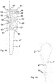
- Figures 9-14 show a variant of the first embodiment of the device 3 'according to the invention. It in turn has a first, cup-shaped part 30 and an insert 40 which can be inserted therein. The operation of this variant is the same as that of the device 3 Figures 1-8 .
- the shape of the cup-shaped part 30 and the insert 40 is angular in this variant.
- Part 30 as in Figure 10 shown, with a bottom 31 and peripheral edge 32 in turn has a recess 33 in the edge 32 and two openings 34 and 35 through which the cord is passed.
- the two openings 34 are arranged on both sides of the recess 33, the two further openings 35 being on the opposite side of the part 30.
- a pin 36 is in turn arranged for the positioning of a spring.
- the associated insert 40 as in Figures 11a and b with an upper surface 41 and circumferential side surface 42 has at one point a recess 43 which leads into a groove 44 with a U-turn, a central part 45 being arranged in the middle, enclosed by the groove.
- the middle part 45 has a recess into which the spring 26 can be inserted.
- the Insert 40 has on each side of the recess 43 a laterally extending guide groove 48 through which a cord can be passed. In the case of assembled parts 30 and 40, the positions of the two recesses 33 and 43 match.
- the positions of the four openings 34 and 35 of the cup-shaped part 30 coincide with the entrances and exits of the guide grooves 48 of the insert 40.
- the cord is again placed in the groove 44 with a U-turn and is guided through the recess 43 of the insert 40 and through the recess 33 of the cup-shaped part 30.
- the elements for inhibiting and deflecting the cord in the guide grooves are formed by projections 37 in the cup-shaped part 30, which engage through correspondingly positioned recesses 47 in the insert 40 and protrude into the guide grooves 48.
- the projections 37 are in the Figure 10 and 12th shown.
- the corresponding recesses 47 in the guide grooves 48 of the insert 40 are in the Figures 11a and b shown and in Figure 13a indicated.
- the cord pieces 4a and 4b lead to a musical instrument and the cord pieces 4c in turn lead to a carrying strap or carrying frame on the musician.
- the cord pieces placed in the guide grooves 48 are guided over the projections 37 and thereby deflected as in the Figure 13b is shown.
- the deflection is in this example in the direction perpendicular to the bottom 31 of the part 30 and the surface 41 of the insert 40. In the example according to the Figures 1-9 however, the deflection is in a direction parallel to the bottom surfaces 11 and 21 of the two parts 10 and 20. Their function of causing friction to increase the stability of the device is the same in both exemplary embodiments.
- Figure 14 shows in a cross section the deflection of the cord 4 by means of the projections 37, which protrudes through the recess 47 into the guide groove 48.
- the figure shows the situation with the spring pressed. If the spring is relaxed, the insert 40 rises and the cord becomes, as in the example in Figure 8 , clamped and locked between the upper edge 34 'and 35' of the opening 34 or 35 and the lower surface 48 'of the guide groove 48.
- Figure 15 shows the device 50 according to the second embodiment for use with flat cord tapes.
- the device 50 for length adjustment of tapes or flat cords 4 ', 4 "in turn has an outer, cup-shaped part 51 and an insert 52.
- the tapes 4', 4", for example woven tapes, pass through an eyelet 5 'with a hook 5 that can be attached to a musical instrument, such as a saxophone.
- Figure 16 shows the guiding of the bands 4 ', 4 "through the two parts 51 and 52.
- the cup-shaped part 51 has an inlet opening 53 and the insert part has a first opening 54 and a second, opposite opening 55. These have an elongated cross section which The ends of the strips 4 ', 4 "are held in the insert 52 in a groove with a recess through which the strips 4', 4" are led out.
- the insert 52 also has a channel 56 in it Fall a passage 56.
- Figure 17 shows the insert part 52 with a recess 57, into which two strips 4 ', 4 "are placed, which are guided by a groove 58 with a U-shaped U-turn.
- the groove 58 is defined by the peripheral edge 59 of the insert 52 and a middle part 60 is formed.
- a depression 61 In the middle part 60 there is a depression 61 for the use of a spring 62 (see Figure 18 ).
- the strips 4 ', 4 have a hole near their ends, which is placed over the central part 60 with the spring 62, whereby the strips are held there.
- FIG 18 shows the guidance of the bands 4 ', 4 "in the two parts 51 and 52.
- the two bands 4', 4" are arranged in the groove 58 by placing their hole over the middle part 62, the middle part 62 in a recess 62 'engages in the bottom of the cup-shaped part 51.
- the bands 4 ', 4 "lead from the groove 58 through the recess 57 of the insert 52 through the inlet opening 53 in the cup-shaped part 51 out of the device 50. After passing through an eyelet (as in FIG Figure 15 shown) feed the bands through the first opening 54 of the cup-shaped part 51 into the device 50 and through the entrance 63 in the passage 56 in the insert 52.
- the belts 4 ', 4 are guided over elements to inhibit their movement, which in this example are formed by surfaces 64 and 65 which are angled to one another and which are connected to one another by a further surface. Lead through an exit 66 of the passage 56 the straps to the second opening 55 of the cup-shaped part 51 out of the device.
- the two straps 4 ', 4 then lead to a carrying strap 2 as in FIG Figure 19 shown that can be placed around the neck of a musician.
- Figure 20 shows the insert part 52 in perspective with the groove 58 with the central part 60 for holding the tapes.
- the recess 61 for the placement of a spring is shown.
- a recess 57 in the peripheral edge 59 of the insert part 51 leads into the groove and out of the groove 58.
- the entrance 63 to the passage 56 is arranged.
- the angled surfaces 64 and 65 which inhibit the movement of the tapes through the passage.
- the exit 66 from the passage 56 is on the rear side of the insert 52.
- Figure 21 shows the cup-shaped outer part 52 in perspective and in particular in its peripheral wall 70 the entrance opening 53 and the separate first opening 54.
- the second opening 55 is located on the rear side of the cup-shaped part 51.
- the openings 53, 54 and 55 are correct when assembling the two parts 51 and 52 with the recess 57 or with the inlet 63 or with the outlet 66 of the passage 56. In other words, when the spring is relaxed, these openings partially match with one another, so that the strips are clamped in the openings. When the spring is compressed, the cross sections of these openings are completely in line with one another so that the belts can be moved.
- the depression 62 ′ is arranged, into which the middle part 60 fits.
- Figure 22 shows the shape of the straps 4 ', 4 "as they would lie one above the other in the device 50. Near their ends they have a hole 67 which can be placed over the middle part 60.
Landscapes
- Engineering & Computer Science (AREA)
- Physics & Mathematics (AREA)
- Acoustics & Sound (AREA)
- Multimedia (AREA)
- General Engineering & Computer Science (AREA)
- Mechanical Engineering (AREA)
- Auxiliary Devices For Music (AREA)
- Electrophonic Musical Instruments (AREA)
- Storing, Repeated Paying-Out, And Re-Storing Of Elongated Articles (AREA)
Applications Claiming Priority (1)
| Application Number | Priority Date | Filing Date | Title |
|---|---|---|---|
| CH00014/19A CH715715A1 (de) | 2019-01-09 | 2019-01-09 | Verstellbare Tragevorrichtung für ein Musikinstrument. |
Publications (2)
| Publication Number | Publication Date |
|---|---|
| EP3680892A1 true EP3680892A1 (fr) | 2020-07-15 |
| EP3680892B1 EP3680892B1 (fr) | 2022-11-30 |
Family
ID=69137810
Family Applications (1)
| Application Number | Title | Priority Date | Filing Date |
|---|---|---|---|
| EP20150378.6A Active EP3680892B1 (fr) | 2019-01-09 | 2020-01-06 | Dispositif de support réglable pour un instrument de musique |
Country Status (6)
| Country | Link |
|---|---|
| US (1) | US10964297B2 (fr) |
| EP (1) | EP3680892B1 (fr) |
| JP (1) | JP7427224B2 (fr) |
| CN (1) | CN111429867B (fr) |
| CH (1) | CH715715A1 (fr) |
| ES (1) | ES2934585T3 (fr) |
Families Citing this family (4)
| Publication number | Priority date | Publication date | Assignee | Title |
|---|---|---|---|---|
| CH715715A1 (de) * | 2019-01-09 | 2020-07-15 | Jancic Silvin | Verstellbare Tragevorrichtung für ein Musikinstrument. |
| US11122867B1 (en) * | 2019-09-08 | 2021-09-21 | Productive Collaboration, LLC | Push button slide mechanism and method of assembling the same |
| US11132982B1 (en) * | 2020-11-25 | 2021-09-28 | Michael Drapkin | Bass clarinet body strap |
| JP1732518S (ja) * | 2022-03-28 | 2022-12-19 | コントローラ用ストラップ |
Citations (6)
| Publication number | Priority date | Publication date | Assignee | Title |
|---|---|---|---|---|
| US1637003A (en) | 1925-12-09 | 1927-07-26 | Lang Albion Slayton | Saxophone cord |
| US2561606A (en) * | 1946-09-06 | 1951-07-24 | Norman C Bates | Sazophone halter |
| US3225984A (en) * | 1964-07-06 | 1965-12-28 | Hyman Raymond | Support for saxophones and similar musical instruments |
| DE3225476A1 (de) * | 1981-07-14 | 1983-02-03 | Jaquith, Hope, Laguna Niguel, Calif. | Musikinstrumentenhalter |
| KR20030091837A (ko) * | 2003-07-26 | 2003-12-03 | 안태진 | 휴대품 장착용 목걸이 |
| CH704201A2 (de) | 2010-12-13 | 2012-06-15 | Silvin M Jancic | Tragevorrichtung für ein Blasinstrument. |
Family Cites Families (30)
| Publication number | Priority date | Publication date | Assignee | Title |
|---|---|---|---|---|
| US1586251A (en) * | 1925-09-19 | 1926-05-25 | Lang Albion Slayton | Saxophone-supporting cord |
| US1891947A (en) * | 1929-08-08 | 1932-12-27 | Edward V Powell | Support for saxophones and similar musical instruments |
| US1789184A (en) * | 1929-11-26 | 1931-01-13 | Albion S Lang | Saxophone cord |
| US2615324A (en) * | 1950-06-08 | 1952-10-28 | Hickok Mfg Co Inc | Key ring |
| US3057526A (en) * | 1959-04-27 | 1962-10-09 | Jaquith Douglas | Musical instrument support |
| DE1231864B (de) * | 1962-09-24 | 1967-01-05 | Max Schmidt | Christbaum- bzw. Dekorationskugel mit eingebautem Spielwerk |
| DE1186738B (de) * | 1963-01-30 | 1965-02-04 | Gauthier Gmbh A | Photographische Kamera mit einem Drahtausloeser |
| US4005765A (en) * | 1973-04-25 | 1977-02-01 | The United States Of America As Represented By The Secretary Of The Navy | Crash load attenuating troop seat |
| US3930289A (en) * | 1974-10-15 | 1976-01-06 | Singular John W | Coupling device |
| JPS6025093Y2 (ja) * | 1980-11-25 | 1985-07-27 | 柳沢管楽器株式会社 | 楽器用ストラップ |
| US4884322A (en) * | 1982-03-30 | 1989-12-05 | Hope Jaquith | Coupling device |
| US4715259A (en) * | 1987-04-06 | 1987-12-29 | Wittman Kenneth L | Strap mounting assembly for electric guitars permitting multiple guitar rotations |
| US4815642A (en) * | 1987-05-15 | 1989-03-28 | Ray Gene S | Ski boot carrier |
| US5437401A (en) * | 1994-02-07 | 1995-08-01 | Seltzer; Richard | Personal harness for carrying articles |
| CA2191657C (fr) * | 1996-11-29 | 2006-03-14 | Noel Doyle | Systeme de corde a linge avec support et epingles ameliorees |
| US6036066A (en) * | 1998-08-21 | 2000-03-14 | Giacona Container Company | Bottled drink carrier apparatus |
| ATE254789T1 (de) * | 1998-10-22 | 2003-12-15 | Mark Erismann | Gitarre oder ähnliches musikinstrument mit einer abnehmbaren körperstütze |
| US20050258205A1 (en) * | 2004-05-21 | 2005-11-24 | Michaels Of Oregon Co. | Shock-absorbing carrying strap |
| US7888572B2 (en) * | 2007-01-05 | 2011-02-15 | Gibson Guitar Corp. | Guitar strap lock |
| US8051542B2 (en) * | 2008-08-13 | 2011-11-08 | Alexander Buday | Detachable lanyard buckle |
| US7655853B1 (en) * | 2009-01-30 | 2010-02-02 | Ricca Tom L | Weight-relieving device for a woodwind instrument |
| US8534515B2 (en) * | 2011-08-04 | 2013-09-17 | M Group, Inc. | Pivoting elastic shoulder support |
| KR20130006014U (ko) * | 2012-04-06 | 2013-10-16 | 장세창 | 색소폰용 숄더 스트랩 |
| GB2550784B (en) * | 2014-04-02 | 2019-01-02 | Earnshaw Troy | A fastening device for a rope-like material used as a part of a belt |
| US9476253B2 (en) * | 2014-04-16 | 2016-10-25 | Yung-Ching Lai | Automatic cord collector of a window blind |
| USD772577S1 (en) * | 2015-01-20 | 2016-11-29 | M Group, Inc. | Elastic shoulder support with shoulder pad and pivot |
| US9492004B1 (en) * | 2015-08-20 | 2016-11-15 | Rick Young | Lightweight suspension harness system for binoculars and method of use |
| US9990910B2 (en) * | 2016-01-15 | 2018-06-05 | D'addario & Company, Inc. | Locking strap mechanism |
| US10070700B1 (en) * | 2017-08-31 | 2018-09-11 | Oculus Vr, Llc | Lanyard adjuster |
| CH715715A1 (de) * | 2019-01-09 | 2020-07-15 | Jancic Silvin | Verstellbare Tragevorrichtung für ein Musikinstrument. |
-
2019
- 2019-01-09 CH CH00014/19A patent/CH715715A1/de unknown
-
2020
- 2020-01-06 EP EP20150378.6A patent/EP3680892B1/fr active Active
- 2020-01-06 ES ES20150378T patent/ES2934585T3/es active Active
- 2020-01-08 US US16/737,287 patent/US10964297B2/en active Active
- 2020-01-09 CN CN202010024239.8A patent/CN111429867B/zh active Active
- 2020-01-09 JP JP2020001876A patent/JP7427224B2/ja active Active
Patent Citations (6)
| Publication number | Priority date | Publication date | Assignee | Title |
|---|---|---|---|---|
| US1637003A (en) | 1925-12-09 | 1927-07-26 | Lang Albion Slayton | Saxophone cord |
| US2561606A (en) * | 1946-09-06 | 1951-07-24 | Norman C Bates | Sazophone halter |
| US3225984A (en) * | 1964-07-06 | 1965-12-28 | Hyman Raymond | Support for saxophones and similar musical instruments |
| DE3225476A1 (de) * | 1981-07-14 | 1983-02-03 | Jaquith, Hope, Laguna Niguel, Calif. | Musikinstrumentenhalter |
| KR20030091837A (ko) * | 2003-07-26 | 2003-12-03 | 안태진 | 휴대품 장착용 목걸이 |
| CH704201A2 (de) | 2010-12-13 | 2012-06-15 | Silvin M Jancic | Tragevorrichtung für ein Blasinstrument. |
Also Published As
| Publication number | Publication date |
|---|---|
| CN111429867A (zh) | 2020-07-17 |
| EP3680892B1 (fr) | 2022-11-30 |
| CH715715A1 (de) | 2020-07-15 |
| US10964297B2 (en) | 2021-03-30 |
| JP7427224B2 (ja) | 2024-02-05 |
| ES2934585T3 (es) | 2023-02-23 |
| US20200219471A1 (en) | 2020-07-09 |
| CN111429867B (zh) | 2025-05-02 |
| JP2020112797A (ja) | 2020-07-27 |
Similar Documents
| Publication | Publication Date | Title |
|---|---|---|
| EP3680892B1 (fr) | Dispositif de support réglable pour un instrument de musique | |
| AT395803B (de) | Verschnuerung fuer einen schischuh | |
| DE69501922T2 (de) | Schliessvorrichtung, insbesondere für sportschuhe | |
| DE102007062735B3 (de) | Selbstligierendes kieferorthopädisches Bracket | |
| DE102008015583A1 (de) | Kapodaster | |
| DE29916884U1 (de) | Chirurgisches Cerclageband | |
| DE69427276T2 (de) | Tremolovorrichtung | |
| AT523145B1 (de) | Schuh, insbesondere Einsatzstiefel, mit einem Schuh-Schnürsystem | |
| DE19931382C2 (de) | Kinnhalter für ein Musikinstrument | |
| DE102019122136A1 (de) | Kabelbinder | |
| DE3225476A1 (de) | Musikinstrumentenhalter | |
| WO2011117367A1 (fr) | Cheville pour instrument à cordes | |
| DE2600226A1 (de) | Spiralschlauchschelde | |
| DE10117254C1 (de) | Nagelkorrekturspange | |
| DE102011014903B4 (de) | Schnürvorrichtung für einen Schuh | |
| EP3872943A1 (fr) | Dispositif porte-câble | |
| DE102007042183B4 (de) | Halter zum Zusammenhalten einer Vielzahl von länglichen Gegenständen, insbesondere zum Zusammenhalten von Kabeln | |
| DE10352420A1 (de) | Saitenspannvorrichtung für ein Saiteninstrument | |
| DE939785C (de) | Befestigungsschelle | |
| DE19506384C1 (de) | Bindung für das Skispringen oder den Tourenskilauf, insbesondre den Skilauf im Telemark-Stil | |
| DE10326608B4 (de) | Spannvorrichtung zur lösbaren Festlegung eines Klemmgutes | |
| EP2981954B1 (fr) | Dispositif servant à fixer une anche tubulaire simple au niveau de l'embout d'un instrument à vent à anche tubulaire simple | |
| EP1917148B1 (fr) | Dispositif pour maintenir des feuilles pliees et empilees dans une chemise | |
| DE102022123402A1 (de) | Haarbinder | |
| DE2350382C3 (de) | Vorrichtung mit Zugdrähten zur Einstellung des Biegewinkels einer flexiblen Endoskopspitze |
Legal Events
| Date | Code | Title | Description |
|---|---|---|---|
| PUAI | Public reference made under article 153(3) epc to a published international application that has entered the european phase |
Free format text: ORIGINAL CODE: 0009012 |
|
| STAA | Information on the status of an ep patent application or granted ep patent |
Free format text: STATUS: THE APPLICATION HAS BEEN PUBLISHED |
|
| AK | Designated contracting states |
Kind code of ref document: A1 Designated state(s): AL AT BE BG CH CY CZ DE DK EE ES FI FR GB GR HR HU IE IS IT LI LT LU LV MC MK MT NL NO PL PT RO RS SE SI SK SM TR |
|
| AX | Request for extension of the european patent |
Extension state: BA ME |
|
| STAA | Information on the status of an ep patent application or granted ep patent |
Free format text: STATUS: REQUEST FOR EXAMINATION WAS MADE |
|
| 17P | Request for examination filed |
Effective date: 20201216 |
|
| RBV | Designated contracting states (corrected) |
Designated state(s): AL AT BE BG CH CY CZ DE DK EE ES FI FR GB GR HR HU IE IS IT LI LT LU LV MC MK MT NL NO PL PT RO RS SE SI SK SM TR |
|
| STAA | Information on the status of an ep patent application or granted ep patent |
Free format text: STATUS: EXAMINATION IS IN PROGRESS |
|
| 17Q | First examination report despatched |
Effective date: 20210311 |
|
| GRAP | Despatch of communication of intention to grant a patent |
Free format text: ORIGINAL CODE: EPIDOSNIGR1 |
|
| STAA | Information on the status of an ep patent application or granted ep patent |
Free format text: STATUS: GRANT OF PATENT IS INTENDED |
|
| INTG | Intention to grant announced |
Effective date: 20210927 |
|
| GRAJ | Information related to disapproval of communication of intention to grant by the applicant or resumption of examination proceedings by the epo deleted |
Free format text: ORIGINAL CODE: EPIDOSDIGR1 |
|
| STAA | Information on the status of an ep patent application or granted ep patent |
Free format text: STATUS: EXAMINATION IS IN PROGRESS |
|
| INTC | Intention to grant announced (deleted) | ||
| GRAP | Despatch of communication of intention to grant a patent |
Free format text: ORIGINAL CODE: EPIDOSNIGR1 |
|
| STAA | Information on the status of an ep patent application or granted ep patent |
Free format text: STATUS: GRANT OF PATENT IS INTENDED |
|
| INTG | Intention to grant announced |
Effective date: 20220914 |
|
| GRAS | Grant fee paid |
Free format text: ORIGINAL CODE: EPIDOSNIGR3 |
|
| GRAA | (expected) grant |
Free format text: ORIGINAL CODE: 0009210 |
|
| STAA | Information on the status of an ep patent application or granted ep patent |
Free format text: STATUS: THE PATENT HAS BEEN GRANTED |
|
| AK | Designated contracting states |
Kind code of ref document: B1 Designated state(s): AL AT BE BG CH CY CZ DE DK EE ES FI FR GB GR HR HU IE IS IT LI LT LU LV MC MK MT NL NO PL PT RO RS SE SI SK SM TR |
|
| REG | Reference to a national code |
Ref country code: CH Ref legal event code: EP Ref country code: GB Ref legal event code: FG4D Free format text: NOT ENGLISH |
|
| REG | Reference to a national code |
Ref country code: AT Ref legal event code: REF Ref document number: 1535280 Country of ref document: AT Kind code of ref document: T Effective date: 20221215 |
|
| REG | Reference to a national code |
Ref country code: IE Ref legal event code: FG4D Free format text: LANGUAGE OF EP DOCUMENT: GERMAN |
|
| REG | Reference to a national code |
Ref country code: DE Ref legal event code: R096 Ref document number: 502020002075 Country of ref document: DE |
|
| REG | Reference to a national code |
Ref country code: NL Ref legal event code: FP |
|
| REG | Reference to a national code |
Ref country code: ES Ref legal event code: FG2A Ref document number: 2934585 Country of ref document: ES Kind code of ref document: T3 Effective date: 20230223 |
|
| REG | Reference to a national code |
Ref country code: LT Ref legal event code: MG9D |
|
| PG25 | Lapsed in a contracting state [announced via postgrant information from national office to epo] |
Ref country code: SE Free format text: LAPSE BECAUSE OF FAILURE TO SUBMIT A TRANSLATION OF THE DESCRIPTION OR TO PAY THE FEE WITHIN THE PRESCRIBED TIME-LIMIT Effective date: 20221130 Ref country code: PT Free format text: LAPSE BECAUSE OF FAILURE TO SUBMIT A TRANSLATION OF THE DESCRIPTION OR TO PAY THE FEE WITHIN THE PRESCRIBED TIME-LIMIT Effective date: 20230331 Ref country code: NO Free format text: LAPSE BECAUSE OF FAILURE TO SUBMIT A TRANSLATION OF THE DESCRIPTION OR TO PAY THE FEE WITHIN THE PRESCRIBED TIME-LIMIT Effective date: 20230228 Ref country code: LT Free format text: LAPSE BECAUSE OF FAILURE TO SUBMIT A TRANSLATION OF THE DESCRIPTION OR TO PAY THE FEE WITHIN THE PRESCRIBED TIME-LIMIT Effective date: 20221130 Ref country code: FI Free format text: LAPSE BECAUSE OF FAILURE TO SUBMIT A TRANSLATION OF THE DESCRIPTION OR TO PAY THE FEE WITHIN THE PRESCRIBED TIME-LIMIT Effective date: 20221130 |
|
| PG25 | Lapsed in a contracting state [announced via postgrant information from national office to epo] |
Ref country code: RS Free format text: LAPSE BECAUSE OF FAILURE TO SUBMIT A TRANSLATION OF THE DESCRIPTION OR TO PAY THE FEE WITHIN THE PRESCRIBED TIME-LIMIT Effective date: 20221130 Ref country code: PL Free format text: LAPSE BECAUSE OF FAILURE TO SUBMIT A TRANSLATION OF THE DESCRIPTION OR TO PAY THE FEE WITHIN THE PRESCRIBED TIME-LIMIT Effective date: 20221130 Ref country code: LV Free format text: LAPSE BECAUSE OF FAILURE TO SUBMIT A TRANSLATION OF THE DESCRIPTION OR TO PAY THE FEE WITHIN THE PRESCRIBED TIME-LIMIT Effective date: 20221130 Ref country code: IS Free format text: LAPSE BECAUSE OF FAILURE TO SUBMIT A TRANSLATION OF THE DESCRIPTION OR TO PAY THE FEE WITHIN THE PRESCRIBED TIME-LIMIT Effective date: 20230330 Ref country code: HR Free format text: LAPSE BECAUSE OF FAILURE TO SUBMIT A TRANSLATION OF THE DESCRIPTION OR TO PAY THE FEE WITHIN THE PRESCRIBED TIME-LIMIT Effective date: 20221130 Ref country code: GR Free format text: LAPSE BECAUSE OF FAILURE TO SUBMIT A TRANSLATION OF THE DESCRIPTION OR TO PAY THE FEE WITHIN THE PRESCRIBED TIME-LIMIT Effective date: 20230301 |
|
| PG25 | Lapsed in a contracting state [announced via postgrant information from national office to epo] |
Ref country code: SM Free format text: LAPSE BECAUSE OF FAILURE TO SUBMIT A TRANSLATION OF THE DESCRIPTION OR TO PAY THE FEE WITHIN THE PRESCRIBED TIME-LIMIT Effective date: 20221130 Ref country code: RO Free format text: LAPSE BECAUSE OF FAILURE TO SUBMIT A TRANSLATION OF THE DESCRIPTION OR TO PAY THE FEE WITHIN THE PRESCRIBED TIME-LIMIT Effective date: 20221130 Ref country code: EE Free format text: LAPSE BECAUSE OF FAILURE TO SUBMIT A TRANSLATION OF THE DESCRIPTION OR TO PAY THE FEE WITHIN THE PRESCRIBED TIME-LIMIT Effective date: 20221130 Ref country code: DK Free format text: LAPSE BECAUSE OF FAILURE TO SUBMIT A TRANSLATION OF THE DESCRIPTION OR TO PAY THE FEE WITHIN THE PRESCRIBED TIME-LIMIT Effective date: 20221130 Ref country code: CZ Free format text: LAPSE BECAUSE OF FAILURE TO SUBMIT A TRANSLATION OF THE DESCRIPTION OR TO PAY THE FEE WITHIN THE PRESCRIBED TIME-LIMIT Effective date: 20221130 |
|
| PG25 | Lapsed in a contracting state [announced via postgrant information from national office to epo] |
Ref country code: SK Free format text: LAPSE BECAUSE OF FAILURE TO SUBMIT A TRANSLATION OF THE DESCRIPTION OR TO PAY THE FEE WITHIN THE PRESCRIBED TIME-LIMIT Effective date: 20221130 Ref country code: AL Free format text: LAPSE BECAUSE OF FAILURE TO SUBMIT A TRANSLATION OF THE DESCRIPTION OR TO PAY THE FEE WITHIN THE PRESCRIBED TIME-LIMIT Effective date: 20221130 |
|
| REG | Reference to a national code |
Ref country code: DE Ref legal event code: R097 Ref document number: 502020002075 Country of ref document: DE |
|
| PG25 | Lapsed in a contracting state [announced via postgrant information from national office to epo] |
Ref country code: LU Free format text: LAPSE BECAUSE OF NON-PAYMENT OF DUE FEES Effective date: 20230106 |
|
| REG | Reference to a national code |
Ref country code: BE Ref legal event code: MM Effective date: 20230131 |
|
| PLBE | No opposition filed within time limit |
Free format text: ORIGINAL CODE: 0009261 |
|
| STAA | Information on the status of an ep patent application or granted ep patent |
Free format text: STATUS: NO OPPOSITION FILED WITHIN TIME LIMIT |
|
| 26N | No opposition filed |
Effective date: 20230831 |
|
| PG25 | Lapsed in a contracting state [announced via postgrant information from national office to epo] |
Ref country code: SI Free format text: LAPSE BECAUSE OF FAILURE TO SUBMIT A TRANSLATION OF THE DESCRIPTION OR TO PAY THE FEE WITHIN THE PRESCRIBED TIME-LIMIT Effective date: 20221130 Ref country code: BE Free format text: LAPSE BECAUSE OF NON-PAYMENT OF DUE FEES Effective date: 20230131 |
|
| PG25 | Lapsed in a contracting state [announced via postgrant information from national office to epo] |
Ref country code: IE Free format text: LAPSE BECAUSE OF NON-PAYMENT OF DUE FEES Effective date: 20230106 |
|
| PG25 | Lapsed in a contracting state [announced via postgrant information from national office to epo] |
Ref country code: MC Free format text: LAPSE BECAUSE OF FAILURE TO SUBMIT A TRANSLATION OF THE DESCRIPTION OR TO PAY THE FEE WITHIN THE PRESCRIBED TIME-LIMIT Effective date: 20221130 |
|
| PG25 | Lapsed in a contracting state [announced via postgrant information from national office to epo] |
Ref country code: MC Free format text: LAPSE BECAUSE OF FAILURE TO SUBMIT A TRANSLATION OF THE DESCRIPTION OR TO PAY THE FEE WITHIN THE PRESCRIBED TIME-LIMIT Effective date: 20221130 |
|
| PG25 | Lapsed in a contracting state [announced via postgrant information from national office to epo] |
Ref country code: BG Free format text: LAPSE BECAUSE OF FAILURE TO SUBMIT A TRANSLATION OF THE DESCRIPTION OR TO PAY THE FEE WITHIN THE PRESCRIBED TIME-LIMIT Effective date: 20221130 |
|
| PG25 | Lapsed in a contracting state [announced via postgrant information from national office to epo] |
Ref country code: BG Free format text: LAPSE BECAUSE OF FAILURE TO SUBMIT A TRANSLATION OF THE DESCRIPTION OR TO PAY THE FEE WITHIN THE PRESCRIBED TIME-LIMIT Effective date: 20221130 |
|
| PG25 | Lapsed in a contracting state [announced via postgrant information from national office to epo] |
Ref country code: CY Free format text: LAPSE BECAUSE OF FAILURE TO SUBMIT A TRANSLATION OF THE DESCRIPTION OR TO PAY THE FEE WITHIN THE PRESCRIBED TIME-LIMIT; INVALID AB INITIO Effective date: 20200106 |
|
| PG25 | Lapsed in a contracting state [announced via postgrant information from national office to epo] |
Ref country code: HU Free format text: LAPSE BECAUSE OF FAILURE TO SUBMIT A TRANSLATION OF THE DESCRIPTION OR TO PAY THE FEE WITHIN THE PRESCRIBED TIME-LIMIT; INVALID AB INITIO Effective date: 20200106 |
|
| PG25 | Lapsed in a contracting state [announced via postgrant information from national office to epo] |
Ref country code: TR Free format text: LAPSE BECAUSE OF FAILURE TO SUBMIT A TRANSLATION OF THE DESCRIPTION OR TO PAY THE FEE WITHIN THE PRESCRIBED TIME-LIMIT Effective date: 20221130 |
|
| REG | Reference to a national code |
Ref country code: CH Ref legal event code: U11 Free format text: ST27 STATUS EVENT CODE: U-0-0-U10-U11 (AS PROVIDED BY THE NATIONAL OFFICE) Effective date: 20260201 |
|
| PGFP | Annual fee paid to national office [announced via postgrant information from national office to epo] |
Ref country code: NL Payment date: 20260121 Year of fee payment: 7 |
|
| PGFP | Annual fee paid to national office [announced via postgrant information from national office to epo] |
Ref country code: GB Payment date: 20260122 Year of fee payment: 7 |
|
| PGFP | Annual fee paid to national office [announced via postgrant information from national office to epo] |
Ref country code: ES Payment date: 20260217 Year of fee payment: 7 |
|
| PGFP | Annual fee paid to national office [announced via postgrant information from national office to epo] |
Ref country code: DE Payment date: 20260120 Year of fee payment: 7 |
|
| PGFP | Annual fee paid to national office [announced via postgrant information from national office to epo] |
Ref country code: AT Payment date: 20260119 Year of fee payment: 7 |
|
| PGFP | Annual fee paid to national office [announced via postgrant information from national office to epo] |
Ref country code: IT Payment date: 20260130 Year of fee payment: 7 |
|
| PGFP | Annual fee paid to national office [announced via postgrant information from national office to epo] |
Ref country code: FR Payment date: 20260121 Year of fee payment: 7 |
|
| PGFP | Annual fee paid to national office [announced via postgrant information from national office to epo] |
Ref country code: CH Payment date: 20260201 Year of fee payment: 7 |