EP3680927A1 - Schlüsselschalter - Google Patents
Schlüsselschalter Download PDFInfo
- Publication number
- EP3680927A1 EP3680927A1 EP19215493.8A EP19215493A EP3680927A1 EP 3680927 A1 EP3680927 A1 EP 3680927A1 EP 19215493 A EP19215493 A EP 19215493A EP 3680927 A1 EP3680927 A1 EP 3680927A1
- Authority
- EP
- European Patent Office
- Prior art keywords
- rear wall
- key switch
- locking
- front part
- switch according
- Prior art date
- Legal status (The legal status is an assumption and is not a legal conclusion. Google has not performed a legal analysis and makes no representation as to the accuracy of the status listed.)
- Granted
Links
Images



Classifications
-
- H—ELECTRICITY
- H01—ELECTRIC ELEMENTS
- H01H—ELECTRIC SWITCHES; RELAYS; SELECTORS; EMERGENCY PROTECTIVE DEVICES
- H01H27/00—Switches operated by a removable member, e.g. key, plug or plate; Switches operated by setting members according to a single predetermined combination out of several possible settings
- H01H27/06—Key inserted and then turned to effect operation of the switch
-
- H—ELECTRICITY
- H01—ELECTRIC ELEMENTS
- H01H—ELECTRIC SWITCHES; RELAYS; SELECTORS; EMERGENCY PROTECTIVE DEVICES
- H01H9/00—Details of switching devices, not covered by groups H01H1/00 - H01H7/00
- H01H9/20—Interlocking, locking, or latching mechanisms
- H01H9/28—Interlocking, locking, or latching mechanisms for locking switch parts by a key or equivalent removable member
- H01H9/285—Locking mechanisms incorporated in the switch assembly and operable by a key or a special tool
-
- H—ELECTRICITY
- H01—ELECTRIC ELEMENTS
- H01H—ELECTRIC SWITCHES; RELAYS; SELECTORS; EMERGENCY PROTECTIVE DEVICES
- H01H27/00—Switches operated by a removable member, e.g. key, plug or plate; Switches operated by setting members according to a single predetermined combination out of several possible settings
- H01H27/06—Key inserted and then turned to effect operation of the switch
- H01H2027/066—Key inserted and then turned to effect operation of the switch having anti-tamper provisions, e.g. avoiding the removal of the lock cylinder
Definitions
- the present invention relates to a key switch with a housing, in which at least one switching insert is arranged, which can be actuated by a locking cylinder fastened in the housing.
- Such key switches are generally known and often have a housing made of cast metal, which is closed by a metal front panel.
- the locking cylinder is fastened to the front plate and is secured by a locking projection formed on the housing or by an additional locking plate.
- a front plate is often provided, which is fastened to the housing with the aid of a screw connection.
- the housing is in two parts and consists of a front part and a rear wall, a front plate being integrated in one piece in the front part and the front part having a circumferential housing side wall. Furthermore, the rear wall is provided with an integrally formed locking projection for a beard of the locking cylinder and the front part and rear wall can be locked together.
- the key switch according to the invention initially differs from known embodiments in that only two components are required to complete the housing and that the front plate of the key switch is integrated in the front part. As a result, a total of only two components are required for the housing and the separate installation of a front plate can be omitted.
- the locking projection is not formed on the inside of the front part, but on the rear wall.
- the front part and the rear wall can be locked together, so that no additional fastening elements such as screws are required for assembling a housing.
- the key switch according to the invention can be manufactured extremely inexpensively, since only two components are required for the housing, which can be assembled without screwing or the like. At the same time, unauthorized opening of the key switch is prevented, since the beard of the locking cylinder is blocked by the locking projection formed on the rear wall when the beard is in its upper vertical position.
- the front part can be made of metal, in particular cast zinc, and the rear wall can be made of plastic. This ensures that the front part, which forms the actual housing, is neither flammable nor easily destroyed.
- the rear wall which closes its rear side, is made of an inexpensive material which (due to its material properties) also enables the formation of a latching connection.
- the cylinder housing of the locking cylinder can be aligned with the front plate on the front. This not only results in an appealing exterior, but also ensures that tools for willfully opening the key switch on the cylinder housing are not possible.
- a spring tongue is formed on the rear wall with a locking hook which can be locked in a locking recess in the front part.
- the front part can be placed on the rear wall in a simple manner, the spring tongue initially springing out slightly until the latching hook is engaged in the locking recess of the front part.
- a locking projection can be formed on the inside of the housing side wall, which engages in a locking recess in the rear wall.
- the rear wall can have an in particular circumferential fastening web on which the front part can be placed. In this way, a stable and easily assembled connection between the two housing components can be achieved.
- the locking recess of the rear wall can be formed in the fastening web, specifically above the locking cylinder.
- a blocking web can be present in the area of the locking recess, which extends to the beard of the locking cylinder when the beard is in its upper vertical position.
- the blocking web completely fills the space above the beard (except for a minimal space to avoid contact), so that a deliberate opening of the key switch (for example by spreading a screwdriver or the like) is not possible.
- the blocking web can be molded onto the fastening web, which favors simple manufacture.
- a holder for the at least one switching insert can be molded onto the rear wall. This makes it possible to dispense with the provision of a separate support for the switch insert and simple installation of the electrical lines is ensured since the switch insert is easily accessible on the rear wall.
- the housing can be assembled without tools, since this eliminates the need for additional fastening elements such as screws or the like, which would have to be manufactured, supplied and assembled separately.
- the locking projection of the rear wall can be at least partially hollow. This allows the stability of the locking projection to be increased, so that it is particularly well secured against deliberate breaking out, particularly when plastic is used as the material for the rear wall.
- the inside of the rear wall can have a marking for a position of the beard in which the front part and rear wall are not locked together.
- the rear wall in the area of the locking projection can have an integrally formed reinforcement block, which is in particular hollow and / or trapezoidal in cross section.
- the area around the locking projection can be additionally reinforced by such a reinforcement block, which in turn prevents the key switch from being opened intentionally.
- the locking cylinder is fastened to the front part and, according to an advantageous embodiment, this can be done by two locking elements running transversely to one another, such as pins or screws, which in turn increases the security against a willful opening of the key switch.
- Fig. 1 shows a perspective front view of a key switch 10, the housing of which is in two parts and consists of a front part 12 and a rear wall 14.
- the front part 12 is made in one piece, for example from cast metal, and has an integrated front plate 16 and an encircling housing side wall 18 connected to it in one piece, which extends as far as the plate-shaped rear wall 14, which has no circumferential side wall.
- the rear wall 14 thus forms a flat rear cover for the front part 12 (cf. Fig. 2 ).
- two directional arrows 20 and 21 are incorporated into the front panel 16, which prescribe the direction of actuation for the key switch 10.
- a locking cylinder 22 is fastened in the housing and more precisely on the front part 12 (cf. also Fig. 5 ), the cylinder housing of the lock cylinder 22 being aligned with the front plate 16 on the front (cf. Fig. 2).
- Fig. 2 illustrates that only the cylinder core 23 of the locking cylinder 22 protrudes slightly from the front plate 16, but that the cylinder housing of the locking cylinder 22 is flush with the front plate 16.
- a bearing shell 24 is molded onto the inside of the front plate 16, which partially surrounds and receives the locking cylinder 22 (a profile half cylinder).
- two securing elements running transversely to one another are provided, namely one that extends horizontally through the bearing shell 24 and the locking cylinder 22 Locking pin 26 and a locking screw 28 extending transversely to the locking pin 26 vertically from below through the bearing shell 24 and locking cylinder 22.
- switching inserts 30 and 32 are two buttons, each of which is inserted into a holder 34, 36, which is integrally formed on the rear wall 14.
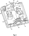
- the rear wall 14 is basically plate-shaped and on its in Fig. 3 and Fig. 4 visible rear side provided with a fastening web 38 which is circumferential in the illustrated embodiment and which extends perpendicular to the main surface of the rear wall 14, but which does not form part of the circumferential side wall.
- the circumferential fastening web 38 is dimensioned such that the front part 12 can be placed with its open side onto the rear wall 14 with almost no play.
- additionally bevelled ribs 40 are provided on the outside of the fastening web 38, so that after assembly of the front part 12 and rear wall 14, both components are joined together without play.
- devices are provided above and below the locking cylinder 22 which enable the front part and the rear wall to be assembled without tools.
- the locking cylinder 22 ( Fig. 5 ) there is an integrally formed locking projection 42 on the inside of the housing side wall 18, which is designed to engage in a locking recess 44 ( Fig. 3 ) the rear wall 14 is formed, for which purpose the fastening web 38 is widened somewhat in the direction of the housing interior in the region of the locking recess 44.
- the front part 12 can be placed on the rear wall 14 in such a way that the locking projection 42 first engages in the locking recess 44 and the front part 12 can then be completely placed on the rear wall 14 by a tilting movement.
- a spring tongue 46 is formed on the underside of the rear wall 14 in the region of the fastening web 38, on the underside of which there is a snap hook 48 which is located in a locking recess 50 ( Fig. 5 ) of the front part 12 can be locked.
- the spring tongue 46 springs out slightly inwards and the latching hook 48 is pushed over the inside of the lower housing side wall 18 until the latching hook 48 engages in the locking recess 50 of the front part.
- a circular predetermined breaking point 52 is created between the spring tongue 46 and the rear wall 14 in the region of the fastening web 38, which can be broken open (for example with the aid of a tool) in order to enable a cable passage. It is also possible to form the predetermined breaking point 52 in one piece from a rubber-like material using the two-component method.
- the locking projection 54 is partially hollow in its interior.
- a reinforcing block 56 is formed on the inside of the rear wall 14 above the locking cylinder 22, which is trapezoidal in cross section and hollow in its interior.
- the reinforcement block 56 is connected in one piece to the locking projection 54 via a blocking web 58 which is likewise hollow on the inside.
- the blocking web 58 is formed on the inside of the fastening web 38 and is dimensioned such that the blocking web extends as far as the beard 25 of the locking cylinder 22 when the beard 25 extends in it Fig. 5 shown upper vertical position is. This ensures that there is no space between the beard 25 and the blocking web 58 except for a minimal free space for contactless insertion of the beard, so that the key switch is prevented from being forced open in this position.
- the rear wall of Fig. 4 be attached to a wall or the like.
- the predetermined breaking point 52 or a predetermined breaking point 53 provided on the rear wall 14 can be pierced and the electrical lines can be connected to the switch inserts 30 and 32.
- the switching inserts 30 and 32 only have to be inserted into their holders 34 and 36, so that they are in the in Fig. 3 position shown.
- the beard 25 of the locking cylinder 22 must first be removed from the in Fig. 5 position shown are rotated so that the beard 25 does not collide with the locking projection 54.
- a marking 60 (in the form of a symbol for an open lock) is provided on the inside of the rear wall 14, which indicates a position of the beard 25 in which the front part 12 is placed on the rear wall 14 can be. In this position, the front part 12 and the rear wall 14 are not locked together, so that the two components can be assembled as described above by placing the front part 12 with its open side onto the rear wall 14.
- the locking projection 42 of the front part 12 is inserted into the locking recess 44 of the rear wall, and the housing is subsequently tilted downward, so that the latching hook 48 can snap into the locking recess 50 of the front part.
- the beard 25 of the lock cylinder 22 in the Fig. 5 Moved position shown and the key is removed, the beard 25 engages behind the locking projection 50, so that a release of the two housing components is impossible even if the locking hook 48 should be pressed out of the locking recess 50 of the front part. Since the beard 25 engages behind the locking projection 54 and also the blocking web 58 essentially without play, the front part 12 cannot be tilted away from the rear wall 14, as a result of which effective protection against sabotage is created.
Landscapes
- Lock And Its Accessories (AREA)
- Switch Cases, Indication, And Locking (AREA)
Abstract
Description
- Die vorliegende Erfindung betrifft einen Schlüsselschalter mit einem Gehäuse, in dem zumindest ein Schalteinsatz angeordnet ist, der von einem in dem Gehäuse befestigten Schließzylinder betätigbar ist.
- Derartige Schlüsselschalter sind grundsätzlich bekannt und weisen häufig ein Gehäuse aus Metallguss auf, das durch eine Frontplatte aus Metall verschlossen wird. An der Frontplatte ist dabei der Schließzylinder befestigt, der durch einen an dem Gehäuse angeformten Verriegelungsvorsprung oder durch eine zusätzliche Verriegelungsplatte gesichert ist. Zusätzlich ist häufig eine Frontplatte vorgesehen, die mit Hilfe einer Verschraubung an dem Gehäuse befestigt wird.
- Es ist die Aufgabe der vorliegenden Erfindung, einen Schlüsselschalter nach dem Oberbegriff des Anspruchs 1 derart weiterzubilden, dass dieser außerordentlich kostengünstig hergestellt und auf einfachste Weise zusammengebaut werden kann.
- Die Lösung dieser Aufgabe erfolgt durch die Merkmale des Anspruchs 1 und insbesondere dadurch, dass das Gehäuse zweiteilig ist und aus einem Vorderteil und einer Rückwand besteht, wobei in das Vorderteil eine Frontplatte einstückig integriert ist und das Vorderteil eine umlaufende Gehäuseseitenwand aufweist. Weiterhin ist die Rückwand mit einem einstückig angeformten Verriegelungsvorsprung für einen Bart des Schließzylinders versehen und Vorderteil und Rückwand sind miteinander verrastbar.
- Der erfindungsgemäße Schlüsselschalter unterscheidet sich zunächst von bekannten Ausführungsformen darin, dass nur zwei Bauteile benötigt werden, um das Gehäuse zu vervollständigen, und dass die Frontplatte des Schlüsselschalters in das Vorderteil integriert ist. Hierdurch werden insgesamt nur zwei Bauteile für das Gehäuse benötigt und die separate Montage einer Frontplatte kann entfallen.
- Weiterhin ist erfindungsgemäß der Verriegelungsvorsprung nicht im Inneren des Vorderteils, sondern an der Rückwand angeformt. Schließlich sind Vorderteil und Rückwand miteinander verrastbar, so dass für einen Zusammenbau eines Gehäuses keine zusätzlichen Befestigungselemente wie Schrauben erforderlich sind.
- Der erfindungsgemäße Schlüsselschalter lässt sich außerordentlich kostengünstig fertigen, da für das Gehäuse lediglich zwei Komponenten erforderlich sind, die ohne ein Verschrauben oder dergleichen zusammengebaut werden können. Gleichzeitig ist jedoch ein unbefugtes Öffnen des Schlüsselschalters verhindert, da der Bart des Schließzylinders durch den an der Rückwand angeformten Verriegelungsvorsprung blockiert ist, wenn sich der Bart in seiner oberen Vertikalposition befindet.
- Vorteilhafte Ausführungsformen der Erfindung sind in der Beschreibung, der Zeichnung sowie in den Unteransprüchen beschrieben.
- Nach einer ersten vorteilhaften Ausführungsform kann das Vorderteil aus Metall, insbesondere aus Zinkguss hergestellt sein und die Rückwand kann aus Kunststoff bestehen. Hierdurch ist gewährleistet, dass das Vorderteil, welches das eigentliche Gehäuse bildet, weder entflammbar noch auf einfache Weise zerstörbar ist. Gleichzeitig ist die seine Rückseite verschließende Rückwand aus einem kostengünstigen Material hergestellt, das zudem (aufgrund seiner Materialeigenschaft) die Ausbildung einer Rastverbindung ermöglicht.
- Nach einer weiteren vorteilhaften Ausführungsform kann das Zylindergehäuse des Schließzylinders frontseitig mit der Frontplatte fluchten. Hierdurch ergibt sich nicht nur ein ansprechendes Äußeres, sondern es ist auch dafür gesorgt, dass ein Ansetzen von Werkzeugen zum mutwilligen Öffnen des Schlüsselschalters an dem Zylindergehäuse nicht möglich ist.
- Nach einer weiteren vorteilhaften Ausführungsform ist an der Rückwand eine Federzunge mit einem Rasthaken angeformt, der in einer Verriegelungsaussparung des Vorderteils verrastbar ist. Bei dieser Ausführungsform kann das Vorderteil auf einfache Weise auf die Rückwand aufgesetzt werden, wobei die Federzunge zunächst leicht ausfedert, bis der Rasthaken in die Verriegelungsaussparung des Vorderteils eingerastet ist.
- Nach einer weiteren vorteilhaften Ausführungsform kann an der Innenseite der Gehäuseseitenwand ein Verriegelungsvorsprung angeformt sein, der in eine Verriegelungsaussparung der Rückwand eingreift. Hierdurch lässt sich (beispielsweise zusätzlich zu der vorstehend beschriebenen Rastverbindung) eine Verriegelung zwischen Rückwand und Vorderteil erreichen, so dass das Vorderteil beispielsweise zunächst mit dem Verriegelungsvorsprung in die Verriegelungsaussparung eingesetzt werden kann, woraufhin anschließend durch eine Kippbewegung ein schließendes Verrasten der beiden Gehäusekomponenten erfolgt.
- Nach einer weiteren vorteilhaften Ausführungsform kann die Rückwand einen insbesondere umlaufenden Befestigungssteg aufweisen, auf den das Vorderteil aufsetzbar ist. Hierdurch lässt sich eine stabile und einfach zusammenbaubare Verbindung zwischen den beiden Gehäusekomponenten erzielen.
- Nach einer weiteren vorteilhaften Ausführungsform kann die Verriegelungsaussparung der Rückwand in dem Befestigungssteg ausgebildet sein und zwar oberhalb des Schließzylinders.
- Nach einer weiteren vorteilhaften Ausführungsform kann im Bereich der Verriegelungsaussparung ein Blockiersteg vorhanden sein, der sich bis zu dem Bart des Schließzylinders erstreckt, wenn sich der Bart in seiner oberen Vertikalposition befindet. Mit anderen Worten füllt der Blockiersteg den Raum oberhalb des Bartes (bis auf einen minimalen Zwischenraum zur Vermeidung einer Berührung) vollständig aus, so dass ein mutwilliges Öffnen des Schlüsselschalters (beispielsweise durch Einspreizen eines Schraubendrehers oder dergleichen) nicht möglich ist.
- Nach einer weiteren vorteilhaften Ausführungsform kann der Blockiersteg an dem Befestigungssteg angeformt sein, was eine einfache Herstellung begünstigt.
- Nach einer weiteren vorteilhaften Ausführungsform kann eine Halterung für den mindestens einen Schalteinsatz an der Rückwand angeformt sein. Hierdurch kann auf das Vorsehen eines separaten Trägers für den Schalteinsatz verzichtet werden und es ist eine einfache Montage der elektrischen Leitungen gewährleistet, da der Schalteinsatz an der Rückwand leicht zugänglich ist.
- Besonders vorteilhaft ist es, wenn das Gehäuse werkzeuglos zusammenbaubar ist, da hierdurch auf zusätzliche Befestigungselemente wie Schrauben oder dergleichen verzichtet werden kann, die separat hergestellt, geliefert und montiert werden müssten.
- Nach einer weiteren vorteilhaften Ausführungsform kann der Verriegelungsvorsprung der Rückwand zumindest teilweise hohl ausgebildet sein. Hierdurch lässt sich die Stabilität des Verriegelungsvorsprungs erhöhen, so dass dieser insbesondere bei Verwendung von Kunststoff als Material für die Rückwand gegen ein mutwilliges Herausbrechen besonders gut gesichert ist.
- Nach einer weiteren vorteilhaften Ausführungsform kann die Innenseite der Rückwand eine Markierung für eine Position des Bartes aufweisen, in welcher Vorderteil und Rückwand nicht miteinander verriegelt sind. Eine solche Ausbildung der Rückwand erleichtert die Montage, da die erforderliche Schlüsselstellung, die für einen Zusammenbau von Vorderteil und Rückwand erforderlich ist, vorgegeben ist.
- Nach einer weiteren vorteilhaften Ausführungsform kann die Rückwand im Bereich des Verriegelungsvorsprungs einen angeformten Verstärkungsblock aufweisen, der insbesondere hohl und/oder im Querschnitt trapezförmig ausgebildet ist. Durch einen solchen Verstärkungsblock kann der Bereich um den Verriegelungsvorsprung herum zusätzlich verstärkt werden, was wiederum ein mutwilliges Öffnen des Schlüsselschalters verhindert.
- Erfindungsgemäß ist der Schließzylinder an dem Vorderteil befestigt und nach einer vorteilhaften Ausführungsform kann dies durch zwei quer zueinander verlaufende Sicherungselemente, wie Stifte oder Schrauben, erfolgen, was wiederum die Sicherheit gegen ein mutwilliges Öffnen des Schlüsselschalters erhöht.
- Nachfolgend wird die vorliegende Erfindung rein beispielhaft anhand einer vorteilhaften Ausführungsform und unter Bezugnahme auf die beigefügten Zeichnungen beschrieben. Es zeigen:
- Fig. 1
- eine perspektivische Vorderansicht eines Schlüsselschalters;
- Fig. 2
- eine Seitenansicht des Schlüsselschalters von
Fig. 1 ; - Fig. 3
- eine perspektivische Ansicht der Rückwand des Schlüssel-schalters von
Fig. 1 mit zwei eingesetzten Schalteinsätzen; - Fig. 4
- eine weitere perspektivische Ansicht der Rückwand ohne Schalteinsätze; und
- Fig. 5
- eine perspektivische Ansicht auf die Rückseite des Vorderteils von
Fig. 1 mit darin befindlichem Schließzylinder. -
Fig. 1 zeigt eine perspektivische Vorderansicht eines Schlüsselschalters 10, dessen Gehäuse zweiteilig ist und aus einem Vorderteil 12 und einer Rückwand 14 besteht. Das Vorderteil 12 ist bei dem dargestellten Ausführungsbeispiel einstückig, beispielsweise aus Metallguss hergestellt und weist eine integrierte Frontplatte 16 sowie eine damit einstückig verbundene umlaufende Gehäuseseitenwand 18 auf, die sich bis zu der plattenförmigen Rückwand 14 erstreckt, die keine umlaufende Seitenwand aufweist. Die Rückwand 14 bildet somit einen flachen hinteren Deckel für das Vorderteil 12 (vgl.Fig. 2 ). Hierbei sind in die Frontplatte 16 zwei Richtungspfeile 20 und 21 eingearbeitet, welche die Betätigungsrichtung für den Schlüsselschalter 10 vorgeben. - In dem Gehäuse und genauer gesagt an dem Vorderteil 12 ist ein Schließzylinder 22 befestigt (vgl. auch
Fig. 5 ), wobei das Zylindergehäuse des Schließzylinders 22 frontseitig mit der Frontplatte 16 fluchtet (vgl.Fig. 2). Fig. 2 verdeutlicht, dass lediglich der Zylinderkern 23 des Schließzylinders 22 geringfügig von der Frontplatte 16 vorsteht, dass jedoch das Zylindergehäuse des Schließzylinders 22 bündig mit der Frontplatte 16 abschließt. - Die Befestigung des Schließzylinders 22 an dem Vorderteil 12 ist in
Fig. 5 erkennbar und es ist ersichtlich, dass an die Innenseite der Frontplatte 16 eine Lagerschale 24 angeformt ist, die den Schließzylinder 22 (ein Profilhalbzylinder) teilweise umgibt und aufnimmt. Zur Sicherung des Schließzylinders 22 an dem Vorderteil 12 sind zwei quer zueinander verlaufende Sicherungselemente vorgesehen, nämlich ein sich horizontal durch die Lagerschale 24 und den Schließzylinder 22 erstreckender Sicherungsstift 26 sowie eine sich quer zu dem Sicherungsstift 26 vertikal von unten durch Lagerschale 24 und Schließzylinder 22 erstreckende Sicherungsschraube 28. Neben dieser Ausführungsform ist es jedoch auch möglich, den Schließzylinder 22 durch nur ein Sicherungselement zu befestigen. - Im Inneren des Schlüsselschalters 10 sind bei dem dargestellten Ausführungsbeispiel zwei Schalteinsätze 30 und 32 (
Fig. 3 ) vorgesehen, die von einem Bart 25 (Fig. 5 ) des Schlüsselschalters betätigt werden können. Bei dem dargestellten Ausführungsbeispiel handelt es sich bei den Schalteinsätzen 30 und 32 um zwei Taster, die jeweils in eine Halterung 34, 36 eingesetzt sind, die einstückig an der Rückwand 14 angeformt ist. - Wie die
Fig. 3 undFig. 4 verdeutlichen, ist die Rückwand 14 grundsätzlich plattenförmig ausgebildet und auf ihrer inFig. 3 undFig. 4 sichtbaren Rückseite mit einem Befestigungssteg 38 versehen, der bei dem dargestellten Ausführungsbeispiel umlaufend ausgebildet ist und der sich senkrecht zur Hauptfläche der Rückwand 14 erstreckt, der jedoch keinen Teil der umlaufenden Seitenwand bildet. Der umlaufende Befestigungssteg 38 ist so dimensioniert, dass das Vorderteil 12 nahezu spielfrei mit seiner offenen Seite auf die Rückwand 14 aufgesetzt werden kann. Für einen Toleranzausgleich sind zusätzlich an der Oberseite angeschrägte Rippen 40 an der Außenseite des Befestigungsstegs 38 vorgesehen, so dass nach einem Zusammenbau von Vorderteil 12 und Rückwand 14 beide Komponenten spielfrei zusammengefügt sind. - Für eine Verriegelung bzw. eine Verrastung von Vorderteil 12 und Rückwand 14 sind oberhalb und unterhalb des Schließzylinders 22 Einrichtungen vorgesehen, die einen werkzeuglosen Zusammenbau von Vorderteil und Rückwand ermöglichen.
- Oberhalb des Schließzylinders 22 (
Fig. 5 ) befindet sich an der Innenseite der Gehäuseseitenwand 18 ein angeformter Verriegelungsvorsprung 42, der für einen Eingriff in eine Verriegelungsaussparung 44 (Fig. 3 ) der Rückwand 14 ausgebildet ist, wozu der Befestigungssteg 38 im Bereich der Verriegelungsaussparung 44 etwas in Richtung des Gehäuseinneren verbreitert ist. Für einen Zusammenbau kann das Vorderteil 12 auf die Rückwand 14 so aufgesetzt werden, dass zunächst der Verriegelungsvorsprung 42 in die Verriegelungsaussparung 44 eingreift und das Vorderteil 12 anschließend durch eine Kippbewegung vollständig auf die Rückwand 14 aufgesetzt werden kann. Um dabei eine Rastverbindung zwischen Vorderteil 12 und Rückwand 14 zu ermöglichen, ist an der Unterseite der Rückwand 14 im Bereich des Befestigungsstegs 38 eine Federzunge 46 angeformt, an deren Unterseite sich ein Rasthaken 48 befindet, der in einer Verriegelungsaussparung 50 (Fig. 5 ) des Vorderteils 12 verrastbar ist. - Bei der oben beschriebenen Kippbewegung federt somit die Federzunge 46 leicht nach innen aus und der Rasthaken 48 schiebt sich über die Innenseite der unteren Gehäuseseitenwand 18, bis der Rasthaken 48 in die Verriegelungsaussparung 50 des Vorderteils eingreift.
- Wie die
Fig. 1 ,4 und5 in diesem Zusammenhang verdeutlichen, ist zwischen der Federzunge 46 und der Rückwand 14 im Bereich des Befestigungsstegs 38 eine kreisförmige Sollbruchstelle 52 geschaffen, die (z.B. mit Hilfe eines Werkzeugs) aufbrechbar ist, um eine Kabeldurchführung zu ermöglichen. Auch ist es möglich, die Sollbruchstelle 52 im Zwei-Komponenten-Verfahren aus einem gummiartigen Material einstückig anzuformen. - Um ein ungewolltes Öffnen des Schlüsselschalters bei abgezogenem Schlüssel, d.h. in einer Position, in der sich der Bart 25 in der in
Fig. 5 dargestellten oberen Vertikalposition befindet, zu verhindern, ist an der Rückwand 14 und genauer gesagt an dem Befestigungssteg 38 im Bereich der Verriegelungsaussparung 44 ein einstückig angeformter Verriegelungsvorsprung 54 vorgesehen, der von dem Bart 25 hintergriffen wird, wenn sich dieser in der inFig. 5 dargestellten Position befindet. Nachdem der Schließzylinder 22 fest an dem Vorderteil 12 montiert ist, ist dadurch ein Lösen von Vorderteil und Rückwand verhindert. - Zur Erhöhung der Stabilität ist der Verriegelungsvorsprung 54 in seinem Inneren teilweise hohl ausgebildet.
- Wie insbesondere in
Fig. 4 erkennbar ist, ist an der Innenseite der Rückwand 14 oberhalb des Schließzylinders 22 ein Verstärkungsblock 56 angeformt, der im Querschnitt trapezförmig und in seinem Inneren hohl ausgebildet ist. Der Verstärkungsblock 56 ist über einen ebenfalls im Inneren hohl ausgebildeten Blockiersteg 58 mit dem Verriegelungsvorsprung 54 einstückig verbunden. Der Blockiersteg 58 ist an die Innenseite des Befestigungsstegs 38 angeformt und so dimensioniert, dass sich der Blockiersteg bis zu dem Bart 25 des Schließzylinders 22 erstreckt, wenn sich der Bart 25 in seiner inFig. 5 dargestellten oberen Vertikalposition befindet. Hierdurch ist dafür gesorgt, dass zwischen dem Bart 25 und dem Blockiersteg 58 bis auf einen minimalen Freiraum zum berührungslosen Einführen des Bartes kein Freiraum vorhanden ist, so dass in dieser Position ein gewaltsames Öffnen des Schlüsselschalters verhindert ist. - Für eine Montage des vorstehend beschriebenen Schließzylinders kann zunächst die Rückwand von
Fig. 4 an einer Mauer oder dergleichen befestigt werden. Zum Einführen der elektrischen Leitungen kann die Sollbruchstelle 52 oder eine an der Rückwand 14 vorgesehene Sollbruchstelle 53 durchstoßen werden und die elektrischen Leitungen können an die Schalteinsätze 30 und 32 angeschlossen werden. Hieraufhin müssen die Schalteinsätze 30 und 32 lediglich in ihre Halterungen 34 und 36 eingesteckt werden, so dass sie sich in der inFig. 3 dargestellten Position befinden. - Zum anschließenden Aufsetzen des Vorderteils 12 auf die Rückwand 14 muss zunächst der Bart 25 des Schließzylinders 22 aus der in
Fig. 5 dargestellten Position verdreht werden, damit der Bart 25 nicht mit dem Verriegelungsvorsprung 54 kollidiert. Um dem Monteur das Auffinden dieser Position zu erleichtern, ist an der Innenseite der Rückwand 14 eine Markierung 60 (in Form eines Symbols für ein offenes Schloss) angebracht, welche eine Position des Bartes 25 anzeigt, in der das Vorderteil 12 auf die Rückwand 14 aufgesetzt werden kann. In dieser Position sind Vorderteil 12 und Rückwand 14 nicht miteinander verriegelt, so dass die beiden Komponenten wie vorstehend beschrieben zusammengebaut werden können, indem das Vorderteil 12 mit seiner offenen Seite auf die Rückwand 14 aufgesetzt wird. Hierbei wird der Verriegelungsvorsprung 42 des Vorderteils 12 in die Verriegelungsaussparung 44 der Rückwand eingesetzt, das Gehäuse anschließend nach unten gekippt, so dass der Rasthaken 48 in die Verriegelungsaussparung 50 des Vorderteils einrasten kann. Wenn anschließend der Bart 25 des Schließzylinders 22 in die inFig. 5 dargestellte Position bewegt und der Schlüssel abgezogen wird, hintergreift der Bart 25 den Verriegelungsvorsprung 50, so dass ein Lösen der beiden Gehäusekomponenten auch dann unmöglich ist, wenn der Rasthaken 48 aus der Verriegelungsaussparung 50 des Vorderteils herausgedrückt werden sollte. Da der Bart 25 den Verriegelungsvorsprung 54 und auch den Blockiersteg 58 im Wesentlichen spielfrei hintergreift, lässt sich auch das Vorderteil 12 nicht von der Rückwand 14 wegkippen, wodurch ein wirksamer Sabotageschutz geschaffen ist.
Claims (15)
- Schlüsselschalter mit einem Gehäuse, in dem zumindest ein Schalteinsatz (30, 32) angeordnet ist, der von einem in dem Gehäuse befestigten Schließzylinder (22) betätigbar ist,
dadurch gekennzeichnet, dass
das Gehäuse zweiteilig ist und aus einem Vorderteil (12) und einer Rückwand (14) besteht,
das Vorderteil (12) eine einstückig integrierte Frontplatte (16) und eine umlaufende Gehäuseseitenwand (18) aufweist,
die Rückwand (14) mit einem einstückig angeformten Verriegelungsvorsprung (54) für einen Bart (25) des Schließzylinders (22) versehen ist, und dass
Vorderteil (12) und Rückwand (14) miteinander verrastbar sind. - Schlüsselschalter nach Anspruch 1,
dadurch gekennzeichnet, dass
das Vorderteil (12) aus Metall und die Rückwand (14) aus Kunststoff bestehen. - Schlüsselschalter nach Anspruch 1 oder 2,
dadurch gekennzeichnet, dass
das Zylindergehäuse des Schließzylinders (22) frontseitig mit der Frontplatte (16) fluchtet. - Schlüsselschalter nach zumindest einem der vorstehenden Ansprüche,
dadurch gekennzeichnet, dass
an der Rückwand (14) eine Federzunge (46) mit einem Rasthaken (48) angeformt ist, der in einer Verriegelungsaussparung (50) des Vorderteils (12) verrastbar ist. - Schlüsselschalter nach zumindest einem der vorstehenden Ansprüche,
dadurch gekennzeichnet, dass
an der Innenseite der Gehäuseseitenwand (18) ein Verriegelungsvorsprung (42) angeformt ist, der in eine Verriegelungsaussparung (44) der Rückwand (14) eingreift. - Schlüsselschalter nach zumindest einem der vorstehenden Ansprüche,
dadurch gekennzeichnet, dass
die Rückwand (14) einen insbesondere umlaufenden Befestigungssteg (38) aufweist, auf den das Vorderteil (12) aufsetzbar ist. - Schlüsselschalter nach zumindest einem der vorstehenden Ansprüche 5 und 6,
dadurch gekennzeichnet, dass
die Verriegelungsaussparung (44) der Rückwand (14) in dem Befestigungssteg (38) ausgebildet ist und zwar oberhalb des Schließzylinders (22). - Schlüsselschalter nach Anspruch 7,
dadurch gekennzeichnet, dass im Bereich der Verriegelungsaussparung (44) ein Blockiersteg (58) vorhanden ist, der sich bis zu dem Bart (25) des Schließzylinders (22) erstreckt, wenn sich der Bart (25) in seiner oberen Vertikalposition befindet. - Schlüsselschalter nach Anspruch 8,
dadurch gekennzeichnet, dass
der Blockiersteg (58) an den Befestigungssteg (38) angeformt ist. - Schlüsselschalter nach zumindest einem der vorstehenden Ansprüche,
dadurch gekennzeichnet, dass
eine Halterung (34, 36) für den Schalteinsatz (30, 32) an der Rückwand (14) angeformt ist. - Schlüsselschalter nach zumindest einem der vorstehenden Ansprüche,
dadurch gekennzeichnet, dass
das Gehäuse werkzeuglos zusammenbaubar ist. - Schlüsselschalter nach zumindest einem der vorstehenden Ansprüche,
dadurch gekennzeichnet, dass
der Verriegelungsvorsprung (44) der Rückwand (14) zumindest teilweise hohl ausgebildet ist. - Schlüsselschalter nach zumindest einem der vorstehenden Ansprüche,
dadurch gekennzeichnet, dass
die Innenseite der Rückwand (14) eine Markierung (60) für eine Position des Bartes (25) aufweist, in welcher Vorderteil (12) und Rückwand (14) nicht miteinander verriegelt sind. - Schlüsselschalter nach zumindest einem der vorstehenden Ansprüche,
dadurch gekennzeichnet, dass
die Rückwand (14) im Bereich des Verriegelungsvorsprungs (44) einen angeformten Verstärkungsblock (56) aufweist, der insbesondere hohl und/oder im Querschnitt trapezförmig ausgebildet ist. - Schlüsselschalter nach zumindest einem der vorstehenden Ansprüche,
dadurch gekennzeichnet, dass
der Schließzylinder (22) an dem Vorderteil (12) durch zwei quer zueinander verlaufende Sicherungselemente (26, 28) befestigt ist.
Applications Claiming Priority (1)
| Application Number | Priority Date | Filing Date | Title |
|---|---|---|---|
| DE102019100305.9A DE102019100305A1 (de) | 2019-01-08 | 2019-01-08 | Schlüsselschalter |
Publications (2)
| Publication Number | Publication Date |
|---|---|
| EP3680927A1 true EP3680927A1 (de) | 2020-07-15 |
| EP3680927B1 EP3680927B1 (de) | 2022-08-17 |
Family
ID=68887235
Family Applications (1)
| Application Number | Title | Priority Date | Filing Date |
|---|---|---|---|
| EP19215493.8A Active EP3680927B1 (de) | 2019-01-08 | 2019-12-12 | Schlüsselschalter |
Country Status (4)
| Country | Link |
|---|---|
| EP (1) | EP3680927B1 (de) |
| CN (2) | CN115394597B (de) |
| DE (1) | DE102019100305A1 (de) |
| ES (1) | ES2927506T3 (de) |
Families Citing this family (1)
| Publication number | Priority date | Publication date | Assignee | Title |
|---|---|---|---|---|
| DE102019100305A1 (de) * | 2019-01-08 | 2020-07-09 | Claus Baumgart | Schlüsselschalter |
Citations (4)
| Publication number | Priority date | Publication date | Assignee | Title |
|---|---|---|---|---|
| FR2595532A1 (fr) * | 1986-03-07 | 1987-09-11 | Amalric Max | Dispositif interrupteur electrique a cle pour maitriser l'usage d'appareils electriques |
| EP0671753A1 (de) * | 1994-03-08 | 1995-09-13 | Baumgart, Gertrud | Schlüsselschalter |
| DE29821401U1 (de) * | 1998-12-05 | 1999-03-04 | Dorma Gmbh + Co. Kg, 58256 Ennepetal | Schlüsseltaster |
| DE10231725A1 (de) * | 2002-07-13 | 2004-01-22 | Abb Patent Gmbh | Schlüsselschalter |
Family Cites Families (10)
| Publication number | Priority date | Publication date | Assignee | Title |
|---|---|---|---|---|
| CN2056282U (zh) * | 1989-09-26 | 1990-04-18 | 范宇航 | 电源插头封闭式电器保护锁 |
| CN2364541Y (zh) * | 1999-03-25 | 2000-02-16 | 王正华 | 锁控开关 |
| ES2222291T3 (es) * | 2001-05-23 | 2005-02-01 | Geba Elektromechanische Und Elektronische Schaltgerate-Fabrik Gmbh | Interruptor de llave con cable de mando. |
| DE202005019656U1 (de) * | 2005-12-16 | 2007-04-19 | Dirak Dieter Ramsauer Konstruktionselemente Gmbh & Co. Kg. | Fallenverschluß |
| EP2019404B1 (de) * | 2007-07-23 | 2014-04-02 | Eurotec Engineering Ltd. | Schlüsselschalter |
| CN201318079Y (zh) * | 2008-10-14 | 2009-09-30 | 金伟达实业有限公司 | 芳香装置外壳的锁接结构 |
| CN204782369U (zh) * | 2015-05-22 | 2015-11-18 | 东莞市怡丰锁业有限公司 | 礼品盒密码锁 |
| CN106285234A (zh) * | 2016-09-14 | 2017-01-04 | 广州凡而芳香日用品有限公司 | 一种启闭机箱外壳的锁具 |
| CN207338773U (zh) * | 2017-10-12 | 2018-05-08 | 法纳通电器(上海)有限公司 | 一种对插头具有压紧作用的防水盒 |
| DE102019100305A1 (de) * | 2019-01-08 | 2020-07-09 | Claus Baumgart | Schlüsselschalter |
-
2019
- 2019-01-08 DE DE102019100305.9A patent/DE102019100305A1/de not_active Withdrawn
- 2019-08-19 CN CN202211013070.1A patent/CN115394597B/zh active Active
- 2019-08-19 CN CN201910763687.7A patent/CN111415835B/zh active Active
- 2019-12-12 ES ES19215493T patent/ES2927506T3/es active Active
- 2019-12-12 EP EP19215493.8A patent/EP3680927B1/de active Active
Patent Citations (4)
| Publication number | Priority date | Publication date | Assignee | Title |
|---|---|---|---|---|
| FR2595532A1 (fr) * | 1986-03-07 | 1987-09-11 | Amalric Max | Dispositif interrupteur electrique a cle pour maitriser l'usage d'appareils electriques |
| EP0671753A1 (de) * | 1994-03-08 | 1995-09-13 | Baumgart, Gertrud | Schlüsselschalter |
| DE29821401U1 (de) * | 1998-12-05 | 1999-03-04 | Dorma Gmbh + Co. Kg, 58256 Ennepetal | Schlüsseltaster |
| DE10231725A1 (de) * | 2002-07-13 | 2004-01-22 | Abb Patent Gmbh | Schlüsselschalter |
Also Published As
| Publication number | Publication date |
|---|---|
| CN115394597B (zh) | 2025-08-19 |
| EP3680927B1 (de) | 2022-08-17 |
| DE102019100305A1 (de) | 2020-07-09 |
| CN111415835A (zh) | 2020-07-14 |
| CN111415835B (zh) | 2022-09-16 |
| ES2927506T3 (es) | 2022-11-07 |
| CN115394597A (zh) | 2022-11-25 |
Similar Documents
| Publication | Publication Date | Title |
|---|---|---|
| EP2182144B1 (de) | Tür- oder Fensterbeschlag | |
| DE102017117002A1 (de) | Vorrichtung zum Befestigen eines Bauteils an einem Trägerbauteil | |
| DE3127151C2 (de) | ||
| EP2055867A1 (de) | Griff mit Verschlusseinsatz | |
| EP1889978A2 (de) | Betätigungsvorrichtung für einen Urinal-Unterputzspüler oder WC-Unterputzspülkasten | |
| EP4442942A1 (de) | Schloss | |
| DE202006004081U1 (de) | Anordnung zur lösbaren Befestigung von Bauteilen an einer Decke oder Wand | |
| EP0616920B1 (de) | Befestigungselement für an Karosserieteilen von Kraftfahrzeugen zu befestigende Ausstattungsteile | |
| EP3680927B1 (de) | Schlüsselschalter | |
| DE29511547U1 (de) | Vorrichtung zur axial unverschieblichen, lösbaren Befestigung einer Handhabe an einem Lagerteil, insbesondere für Türdrücker, Fenstergriffe o.dgl. | |
| EP2019404B1 (de) | Schlüsselschalter | |
| DE19943497A1 (de) | Abdeckvorrichtung für einen in einer Griffplatte o. dgl. eines Türgriffs angeordneten Schliesszylinders eines Kraftfahrzeugtürverschlusses | |
| DE202016007457U1 (de) | Drehriegelschloss | |
| DE102017101748A1 (de) | Gehäuseverschluss für ein Gehäuse eines elektronischen Geräts und dessen Verwendung | |
| EP1518978B1 (de) | Aufnahmetopf für eine Leiste | |
| DE4407678C2 (de) | Schlüsselschalter | |
| DE19925859B4 (de) | Montagehilfe für eine Kraftfahrzeugtürkonstruktion | |
| DE4016285A1 (de) | Schubriegelverschluss | |
| DE10016609B4 (de) | Vorrichtung zur Verbindung einer Stange mit einem Bauteil | |
| DE9300481U1 (de) | Rosette für einen Schließzylinder | |
| WO2012055910A1 (de) | Befestigungseinrichtung | |
| DE3143638A1 (de) | Schliesszylinder | |
| WO2020259887A1 (de) | Gehäuse für einen antrieb sowie antrieb | |
| DE202007016853U1 (de) | Treibstangenantrieb | |
| DE202005003529U1 (de) | Schließvorrichtungs-Anordnung |
Legal Events
| Date | Code | Title | Description |
|---|---|---|---|
| PUAI | Public reference made under article 153(3) epc to a published international application that has entered the european phase |
Free format text: ORIGINAL CODE: 0009012 |
|
| STAA | Information on the status of an ep patent application or granted ep patent |
Free format text: STATUS: THE APPLICATION HAS BEEN PUBLISHED |
|
| AK | Designated contracting states |
Kind code of ref document: A1 Designated state(s): AL AT BE BG CH CY CZ DE DK EE ES FI FR GB GR HR HU IE IS IT LI LT LU LV MC MK MT NL NO PL PT RO RS SE SI SK SM TR |
|
| AX | Request for extension of the european patent |
Extension state: BA ME |
|
| STAA | Information on the status of an ep patent application or granted ep patent |
Free format text: STATUS: REQUEST FOR EXAMINATION WAS MADE |
|
| 17P | Request for examination filed |
Effective date: 20200812 |
|
| RBV | Designated contracting states (corrected) |
Designated state(s): AL AT BE BG CH CY CZ DE DK EE ES FI FR GB GR HR HU IE IS IT LI LT LU LV MC MK MT NL NO PL PT RO RS SE SI SK SM TR |
|
| GRAP | Despatch of communication of intention to grant a patent |
Free format text: ORIGINAL CODE: EPIDOSNIGR1 |
|
| STAA | Information on the status of an ep patent application or granted ep patent |
Free format text: STATUS: GRANT OF PATENT IS INTENDED |
|
| INTG | Intention to grant announced |
Effective date: 20220512 |
|
| GRAS | Grant fee paid |
Free format text: ORIGINAL CODE: EPIDOSNIGR3 |
|
| GRAA | (expected) grant |
Free format text: ORIGINAL CODE: 0009210 |
|
| STAA | Information on the status of an ep patent application or granted ep patent |
Free format text: STATUS: THE PATENT HAS BEEN GRANTED |
|
| AK | Designated contracting states |
Kind code of ref document: B1 Designated state(s): AL AT BE BG CH CY CZ DE DK EE ES FI FR GB GR HR HU IE IS IT LI LT LU LV MC MK MT NL NO PL PT RO RS SE SI SK SM TR |
|
| REG | Reference to a national code |
Ref country code: CH Ref legal event code: EP |
|
| REG | Reference to a national code |
Ref country code: DE Ref legal event code: R096 Ref document number: 502019005327 Country of ref document: DE |
|
| REG | Reference to a national code |
Ref country code: IE Ref legal event code: FG4D Free format text: LANGUAGE OF EP DOCUMENT: GERMAN |
|
| REG | Reference to a national code |
Ref country code: AT Ref legal event code: REF Ref document number: 1512713 Country of ref document: AT Kind code of ref document: T Effective date: 20220915 |
|
| REG | Reference to a national code |
Ref country code: NL Ref legal event code: FP |
|
| REG | Reference to a national code |
Ref country code: ES Ref legal event code: FG2A Ref document number: 2927506 Country of ref document: ES Kind code of ref document: T3 Effective date: 20221107 |
|
| REG | Reference to a national code |
Ref country code: SK Ref legal event code: T3 Ref document number: E 40444 Country of ref document: SK |
|
| REG | Reference to a national code |
Ref country code: LT Ref legal event code: MG9D |
|
| PG25 | Lapsed in a contracting state [announced via postgrant information from national office to epo] |
Ref country code: SE Free format text: LAPSE BECAUSE OF FAILURE TO SUBMIT A TRANSLATION OF THE DESCRIPTION OR TO PAY THE FEE WITHIN THE PRESCRIBED TIME-LIMIT Effective date: 20220817 Ref country code: RS Free format text: LAPSE BECAUSE OF FAILURE TO SUBMIT A TRANSLATION OF THE DESCRIPTION OR TO PAY THE FEE WITHIN THE PRESCRIBED TIME-LIMIT Effective date: 20220817 Ref country code: PT Free format text: LAPSE BECAUSE OF FAILURE TO SUBMIT A TRANSLATION OF THE DESCRIPTION OR TO PAY THE FEE WITHIN THE PRESCRIBED TIME-LIMIT Effective date: 20221219 Ref country code: NO Free format text: LAPSE BECAUSE OF FAILURE TO SUBMIT A TRANSLATION OF THE DESCRIPTION OR TO PAY THE FEE WITHIN THE PRESCRIBED TIME-LIMIT Effective date: 20221117 Ref country code: LV Free format text: LAPSE BECAUSE OF FAILURE TO SUBMIT A TRANSLATION OF THE DESCRIPTION OR TO PAY THE FEE WITHIN THE PRESCRIBED TIME-LIMIT Effective date: 20220817 Ref country code: LT Free format text: LAPSE BECAUSE OF FAILURE TO SUBMIT A TRANSLATION OF THE DESCRIPTION OR TO PAY THE FEE WITHIN THE PRESCRIBED TIME-LIMIT Effective date: 20220817 Ref country code: FI Free format text: LAPSE BECAUSE OF FAILURE TO SUBMIT A TRANSLATION OF THE DESCRIPTION OR TO PAY THE FEE WITHIN THE PRESCRIBED TIME-LIMIT Effective date: 20220817 |
|
| PG25 | Lapsed in a contracting state [announced via postgrant information from national office to epo] |
Ref country code: PL Free format text: LAPSE BECAUSE OF FAILURE TO SUBMIT A TRANSLATION OF THE DESCRIPTION OR TO PAY THE FEE WITHIN THE PRESCRIBED TIME-LIMIT Effective date: 20220817 Ref country code: IS Free format text: LAPSE BECAUSE OF FAILURE TO SUBMIT A TRANSLATION OF THE DESCRIPTION OR TO PAY THE FEE WITHIN THE PRESCRIBED TIME-LIMIT Effective date: 20221217 Ref country code: HR Free format text: LAPSE BECAUSE OF FAILURE TO SUBMIT A TRANSLATION OF THE DESCRIPTION OR TO PAY THE FEE WITHIN THE PRESCRIBED TIME-LIMIT Effective date: 20220817 Ref country code: GR Free format text: LAPSE BECAUSE OF FAILURE TO SUBMIT A TRANSLATION OF THE DESCRIPTION OR TO PAY THE FEE WITHIN THE PRESCRIBED TIME-LIMIT Effective date: 20221118 |
|
| PG25 | Lapsed in a contracting state [announced via postgrant information from national office to epo] |
Ref country code: SM Free format text: LAPSE BECAUSE OF FAILURE TO SUBMIT A TRANSLATION OF THE DESCRIPTION OR TO PAY THE FEE WITHIN THE PRESCRIBED TIME-LIMIT Effective date: 20220817 Ref country code: RO Free format text: LAPSE BECAUSE OF FAILURE TO SUBMIT A TRANSLATION OF THE DESCRIPTION OR TO PAY THE FEE WITHIN THE PRESCRIBED TIME-LIMIT Effective date: 20220817 Ref country code: DK Free format text: LAPSE BECAUSE OF FAILURE TO SUBMIT A TRANSLATION OF THE DESCRIPTION OR TO PAY THE FEE WITHIN THE PRESCRIBED TIME-LIMIT Effective date: 20220817 Ref country code: CZ Free format text: LAPSE BECAUSE OF FAILURE TO SUBMIT A TRANSLATION OF THE DESCRIPTION OR TO PAY THE FEE WITHIN THE PRESCRIBED TIME-LIMIT Effective date: 20220817 |
|
| REG | Reference to a national code |
Ref country code: DE Ref legal event code: R097 Ref document number: 502019005327 Country of ref document: DE |
|
| PG25 | Lapsed in a contracting state [announced via postgrant information from national office to epo] |
Ref country code: EE Free format text: LAPSE BECAUSE OF FAILURE TO SUBMIT A TRANSLATION OF THE DESCRIPTION OR TO PAY THE FEE WITHIN THE PRESCRIBED TIME-LIMIT Effective date: 20220817 |
|
| PLBE | No opposition filed within time limit |
Free format text: ORIGINAL CODE: 0009261 |
|
| STAA | Information on the status of an ep patent application or granted ep patent |
Free format text: STATUS: NO OPPOSITION FILED WITHIN TIME LIMIT |
|
| PG25 | Lapsed in a contracting state [announced via postgrant information from national office to epo] |
Ref country code: AL Free format text: LAPSE BECAUSE OF FAILURE TO SUBMIT A TRANSLATION OF THE DESCRIPTION OR TO PAY THE FEE WITHIN THE PRESCRIBED TIME-LIMIT Effective date: 20220817 |
|
| 26N | No opposition filed |
Effective date: 20230519 |
|
| REG | Reference to a national code |
Ref country code: CH Ref legal event code: PL |
|
| PG25 | Lapsed in a contracting state [announced via postgrant information from national office to epo] |
Ref country code: SI Free format text: LAPSE BECAUSE OF FAILURE TO SUBMIT A TRANSLATION OF THE DESCRIPTION OR TO PAY THE FEE WITHIN THE PRESCRIBED TIME-LIMIT Effective date: 20220817 Ref country code: LU Free format text: LAPSE BECAUSE OF NON-PAYMENT OF DUE FEES Effective date: 20221212 |
|
| PG25 | Lapsed in a contracting state [announced via postgrant information from national office to epo] |
Ref country code: LI Free format text: LAPSE BECAUSE OF NON-PAYMENT OF DUE FEES Effective date: 20221231 Ref country code: IE Free format text: LAPSE BECAUSE OF NON-PAYMENT OF DUE FEES Effective date: 20221212 Ref country code: CH Free format text: LAPSE BECAUSE OF NON-PAYMENT OF DUE FEES Effective date: 20221231 |
|
| PG25 | Lapsed in a contracting state [announced via postgrant information from national office to epo] |
Ref country code: HU Free format text: LAPSE BECAUSE OF FAILURE TO SUBMIT A TRANSLATION OF THE DESCRIPTION OR TO PAY THE FEE WITHIN THE PRESCRIBED TIME-LIMIT; INVALID AB INITIO Effective date: 20191212 |
|
| PG25 | Lapsed in a contracting state [announced via postgrant information from national office to epo] |
Ref country code: CY Free format text: LAPSE BECAUSE OF FAILURE TO SUBMIT A TRANSLATION OF THE DESCRIPTION OR TO PAY THE FEE WITHIN THE PRESCRIBED TIME-LIMIT Effective date: 20220817 |
|
| PG25 | Lapsed in a contracting state [announced via postgrant information from national office to epo] |
Ref country code: MK Free format text: LAPSE BECAUSE OF FAILURE TO SUBMIT A TRANSLATION OF THE DESCRIPTION OR TO PAY THE FEE WITHIN THE PRESCRIBED TIME-LIMIT Effective date: 20220817 Ref country code: IT Free format text: LAPSE BECAUSE OF FAILURE TO SUBMIT A TRANSLATION OF THE DESCRIPTION OR TO PAY THE FEE WITHIN THE PRESCRIBED TIME-LIMIT Effective date: 20220817 |
|
| PG25 | Lapsed in a contracting state [announced via postgrant information from national office to epo] |
Ref country code: MC Free format text: LAPSE BECAUSE OF FAILURE TO SUBMIT A TRANSLATION OF THE DESCRIPTION OR TO PAY THE FEE WITHIN THE PRESCRIBED TIME-LIMIT Effective date: 20220817 |
|
| PG25 | Lapsed in a contracting state [announced via postgrant information from national office to epo] |
Ref country code: MC Free format text: LAPSE BECAUSE OF FAILURE TO SUBMIT A TRANSLATION OF THE DESCRIPTION OR TO PAY THE FEE WITHIN THE PRESCRIBED TIME-LIMIT Effective date: 20220817 |
|
| PG25 | Lapsed in a contracting state [announced via postgrant information from national office to epo] |
Ref country code: BG Free format text: LAPSE BECAUSE OF FAILURE TO SUBMIT A TRANSLATION OF THE DESCRIPTION OR TO PAY THE FEE WITHIN THE PRESCRIBED TIME-LIMIT Effective date: 20220817 |
|
| PG25 | Lapsed in a contracting state [announced via postgrant information from national office to epo] |
Ref country code: MT Free format text: LAPSE BECAUSE OF FAILURE TO SUBMIT A TRANSLATION OF THE DESCRIPTION OR TO PAY THE FEE WITHIN THE PRESCRIBED TIME-LIMIT Effective date: 20220817 |
|
| PG25 | Lapsed in a contracting state [announced via postgrant information from national office to epo] |
Ref country code: TR Free format text: LAPSE BECAUSE OF FAILURE TO SUBMIT A TRANSLATION OF THE DESCRIPTION OR TO PAY THE FEE WITHIN THE PRESCRIBED TIME-LIMIT Effective date: 20220817 |
|
| PGFP | Annual fee paid to national office [announced via postgrant information from national office to epo] |
Ref country code: GB Payment date: 20251219 Year of fee payment: 7 |
|
| PGFP | Annual fee paid to national office [announced via postgrant information from national office to epo] |
Ref country code: AT Payment date: 20251222 Year of fee payment: 7 |
|
| PGFP | Annual fee paid to national office [announced via postgrant information from national office to epo] |
Ref country code: FR Payment date: 20251229 Year of fee payment: 7 Ref country code: NL Payment date: 20251219 Year of fee payment: 7 |
|
| PGFP | Annual fee paid to national office [announced via postgrant information from national office to epo] |
Ref country code: BE Payment date: 20251219 Year of fee payment: 7 |
|
| PGFP | Annual fee paid to national office [announced via postgrant information from national office to epo] |
Ref country code: SK Payment date: 20251210 Year of fee payment: 7 |
|
| PGFP | Annual fee paid to national office [announced via postgrant information from national office to epo] |
Ref country code: ES Payment date: 20260130 Year of fee payment: 7 |
|
| PGFP | Annual fee paid to national office [announced via postgrant information from national office to epo] |
Ref country code: DE Payment date: 20260224 Year of fee payment: 7 |