EP3680930B1 - Système de stockage et procédé de purge dans un système de stockage - Google Patents
Système de stockage et procédé de purge dans un système de stockage Download PDFInfo
- Publication number
- EP3680930B1 EP3680930B1 EP18854967.9A EP18854967A EP3680930B1 EP 3680930 B1 EP3680930 B1 EP 3680930B1 EP 18854967 A EP18854967 A EP 18854967A EP 3680930 B1 EP3680930 B1 EP 3680930B1
- Authority
- EP
- European Patent Office
- Prior art keywords
- shelf
- controller
- purge
- nozzle
- clean gas
- Prior art date
- Legal status (The legal status is an assumption and is not a legal conclusion. Google has not performed a legal analysis and makes no representation as to the accuracy of the status listed.)
- Active
Links
Images



Classifications
-
- B—PERFORMING OPERATIONS; TRANSPORTING
- B65—CONVEYING; PACKING; STORING; HANDLING THIN OR FILAMENTARY MATERIAL
- B65G—TRANSPORT OR STORAGE DEVICES, e.g. CONVEYORS FOR LOADING OR TIPPING, SHOP CONVEYOR SYSTEMS OR PNEUMATIC TUBE CONVEYORS
- B65G1/00—Storing articles, individually or in orderly arrangement, in warehouses or magazines
-
- B—PERFORMING OPERATIONS; TRANSPORTING
- B65—CONVEYING; PACKING; STORING; HANDLING THIN OR FILAMENTARY MATERIAL
- B65G—TRANSPORT OR STORAGE DEVICES, e.g. CONVEYORS FOR LOADING OR TIPPING, SHOP CONVEYOR SYSTEMS OR PNEUMATIC TUBE CONVEYORS
- B65G1/00—Storing articles, individually or in orderly arrangement, in warehouses or magazines
- B65G1/02—Storage devices
- B65G1/04—Storage devices mechanical
- B65G1/137—Storage devices mechanical with arrangements or automatic control means for selecting which articles are to be removed
-
- B—PERFORMING OPERATIONS; TRANSPORTING
- B65—CONVEYING; PACKING; STORING; HANDLING THIN OR FILAMENTARY MATERIAL
- B65G—TRANSPORT OR STORAGE DEVICES, e.g. CONVEYORS FOR LOADING OR TIPPING, SHOP CONVEYOR SYSTEMS OR PNEUMATIC TUBE CONVEYORS
- B65G1/00—Storing articles, individually or in orderly arrangement, in warehouses or magazines
- B65G1/02—Storage devices
- B65G1/04—Storage devices mechanical
- B65G1/0407—Storage devices mechanical using stacker cranes
- B65G1/0421—Storage devices mechanical using stacker cranes with control for stacker crane operations
-
- H—ELECTRICITY
- H10—SEMICONDUCTOR DEVICES; ELECTRIC SOLID-STATE DEVICES NOT OTHERWISE PROVIDED FOR
- H10P—GENERIC PROCESSES OR APPARATUS FOR THE MANUFACTURE OR TREATMENT OF DEVICES COVERED BY CLASS H10
- H10P72/00—Handling or holding of wafers, substrates or devices during manufacture or treatment thereof
- H10P72/10—Handling or holding of wafers, substrates or devices during manufacture or treatment thereof using carriers specially adapted therefor, e.g. front opening unified pods [FOUP]
-
- H—ELECTRICITY
- H10—SEMICONDUCTOR DEVICES; ELECTRIC SOLID-STATE DEVICES NOT OTHERWISE PROVIDED FOR
- H10P—GENERIC PROCESSES OR APPARATUS FOR THE MANUFACTURE OR TREATMENT OF DEVICES COVERED BY CLASS H10
- H10P72/00—Handling or holding of wafers, substrates or devices during manufacture or treatment thereof
- H10P72/10—Handling or holding of wafers, substrates or devices during manufacture or treatment thereof using carriers specially adapted therefor, e.g. front opening unified pods [FOUP]
- H10P72/19—Handling or holding of wafers, substrates or devices during manufacture or treatment thereof using carriers specially adapted therefor, e.g. front opening unified pods [FOUP] closed carriers
- H10P72/1914—Handling or holding of wafers, substrates or devices during manufacture or treatment thereof using carriers specially adapted therefor, e.g. front opening unified pods [FOUP] closed carriers characterised by locking systems
-
- H—ELECTRICITY
- H10—SEMICONDUCTOR DEVICES; ELECTRIC SOLID-STATE DEVICES NOT OTHERWISE PROVIDED FOR
- H10P—GENERIC PROCESSES OR APPARATUS FOR THE MANUFACTURE OR TREATMENT OF DEVICES COVERED BY CLASS H10
- H10P72/00—Handling or holding of wafers, substrates or devices during manufacture or treatment thereof
- H10P72/10—Handling or holding of wafers, substrates or devices during manufacture or treatment thereof using carriers specially adapted therefor, e.g. front opening unified pods [FOUP]
- H10P72/19—Handling or holding of wafers, substrates or devices during manufacture or treatment thereof using carriers specially adapted therefor, e.g. front opening unified pods [FOUP] closed carriers
- H10P72/1924—Handling or holding of wafers, substrates or devices during manufacture or treatment thereof using carriers specially adapted therefor, e.g. front opening unified pods [FOUP] closed carriers characterised by atmosphere control
-
- H—ELECTRICITY
- H10—SEMICONDUCTOR DEVICES; ELECTRIC SOLID-STATE DEVICES NOT OTHERWISE PROVIDED FOR
- H10P—GENERIC PROCESSES OR APPARATUS FOR THE MANUFACTURE OR TREATMENT OF DEVICES COVERED BY CLASS H10
- H10P72/00—Handling or holding of wafers, substrates or devices during manufacture or treatment thereof
- H10P72/10—Handling or holding of wafers, substrates or devices during manufacture or treatment thereof using carriers specially adapted therefor, e.g. front opening unified pods [FOUP]
- H10P72/19—Handling or holding of wafers, substrates or devices during manufacture or treatment thereof using carriers specially adapted therefor, e.g. front opening unified pods [FOUP] closed carriers
- H10P72/1924—Handling or holding of wafers, substrates or devices during manufacture or treatment thereof using carriers specially adapted therefor, e.g. front opening unified pods [FOUP] closed carriers characterised by atmosphere control
- H10P72/1926—Handling or holding of wafers, substrates or devices during manufacture or treatment thereof using carriers specially adapted therefor, e.g. front opening unified pods [FOUP] closed carriers characterised by atmosphere control characterised by the presence of atmosphere modifying elements inside or attached to the closed carrier
-
- H—ELECTRICITY
- H10—SEMICONDUCTOR DEVICES; ELECTRIC SOLID-STATE DEVICES NOT OTHERWISE PROVIDED FOR
- H10P—GENERIC PROCESSES OR APPARATUS FOR THE MANUFACTURE OR TREATMENT OF DEVICES COVERED BY CLASS H10
- H10P72/00—Handling or holding of wafers, substrates or devices during manufacture or treatment thereof
- H10P72/30—Handling or holding of wafers, substrates or devices during manufacture or treatment thereof for conveying, e.g. between different workstations
-
- H—ELECTRICITY
- H10—SEMICONDUCTOR DEVICES; ELECTRIC SOLID-STATE DEVICES NOT OTHERWISE PROVIDED FOR
- H10P—GENERIC PROCESSES OR APPARATUS FOR THE MANUFACTURE OR TREATMENT OF DEVICES COVERED BY CLASS H10
- H10P72/00—Handling or holding of wafers, substrates or devices during manufacture or treatment thereof
- H10P72/30—Handling or holding of wafers, substrates or devices during manufacture or treatment thereof for conveying, e.g. between different workstations
- H10P72/32—Handling or holding of wafers, substrates or devices during manufacture or treatment thereof for conveying, e.g. between different workstations between different workstations
- H10P72/3202—Mechanical details, e.g. rollers or belts
-
- H—ELECTRICITY
- H10—SEMICONDUCTOR DEVICES; ELECTRIC SOLID-STATE DEVICES NOT OTHERWISE PROVIDED FOR
- H10P—GENERIC PROCESSES OR APPARATUS FOR THE MANUFACTURE OR TREATMENT OF DEVICES COVERED BY CLASS H10
- H10P72/00—Handling or holding of wafers, substrates or devices during manufacture or treatment thereof
- H10P72/30—Handling or holding of wafers, substrates or devices during manufacture or treatment thereof for conveying, e.g. between different workstations
- H10P72/32—Handling or holding of wafers, substrates or devices during manufacture or treatment thereof for conveying, e.g. between different workstations between different workstations
- H10P72/3218—Conveying cassettes, containers or carriers
-
- H—ELECTRICITY
- H10—SEMICONDUCTOR DEVICES; ELECTRIC SOLID-STATE DEVICES NOT OTHERWISE PROVIDED FOR
- H10P—GENERIC PROCESSES OR APPARATUS FOR THE MANUFACTURE OR TREATMENT OF DEVICES COVERED BY CLASS H10
- H10P72/00—Handling or holding of wafers, substrates or devices during manufacture or treatment thereof
- H10P72/30—Handling or holding of wafers, substrates or devices during manufacture or treatment thereof for conveying, e.g. between different workstations
- H10P72/32—Handling or holding of wafers, substrates or devices during manufacture or treatment thereof for conveying, e.g. between different workstations between different workstations
- H10P72/3221—Overhead conveying
-
- H—ELECTRICITY
- H10—SEMICONDUCTOR DEVICES; ELECTRIC SOLID-STATE DEVICES NOT OTHERWISE PROVIDED FOR
- H10P—GENERIC PROCESSES OR APPARATUS FOR THE MANUFACTURE OR TREATMENT OF DEVICES COVERED BY CLASS H10
- H10P72/00—Handling or holding of wafers, substrates or devices during manufacture or treatment thereof
- H10P72/30—Handling or holding of wafers, substrates or devices during manufacture or treatment thereof for conveying, e.g. between different workstations
- H10P72/34—Handling or holding of wafers, substrates or devices during manufacture or treatment thereof for conveying, e.g. between different workstations the wafers being stored in a carrier, involving loading and unloading
- H10P72/3404—Storage means
-
- B—PERFORMING OPERATIONS; TRANSPORTING
- B65—CONVEYING; PACKING; STORING; HANDLING THIN OR FILAMENTARY MATERIAL
- B65G—TRANSPORT OR STORAGE DEVICES, e.g. CONVEYORS FOR LOADING OR TIPPING, SHOP CONVEYOR SYSTEMS OR PNEUMATIC TUBE CONVEYORS
- B65G1/00—Storing articles, individually or in orderly arrangement, in warehouses or magazines
- B65G1/02—Storage devices
-
- B—PERFORMING OPERATIONS; TRANSPORTING
- B65—CONVEYING; PACKING; STORING; HANDLING THIN OR FILAMENTARY MATERIAL
- B65G—TRANSPORT OR STORAGE DEVICES, e.g. CONVEYORS FOR LOADING OR TIPPING, SHOP CONVEYOR SYSTEMS OR PNEUMATIC TUBE CONVEYORS
- B65G2201/00—Indexing codes relating to handling devices, e.g. conveyors, characterised by the type of product or load being conveyed or handled
- B65G2201/02—Articles
- B65G2201/0297—Wafer cassette
Definitions
- the present invention which is defined by the appended claims, relates to a storage system, such as a purge stocker, and a purge method in the storage system.
- Purge stockers have shelves and nozzles provided in the shelves; the nozzles are configured to be made in contact with valves in the bottoms of containers, such as FOUPs, stored on the shelves, and are configured to supply clean gas, such as nitrogen gas or clean dry air, into the containers.
- containers such as FOUPs
- Patent Document 1 JP4692584B
- Patent Document 2 JP5557061B
- Patent Document 2 JP5557061B
- This purge stocker has a reduced consumption amount of clean gas, since the cleaning is carried out just in the shelf assigned for the unloading position and since the purge is triggered by the start of movement of the transport apparatus.
- US 2014/017040 A1 teaches an article storage facility including a transport device for transporting containers to a plurality of storage sections.
- An inactive gas feed section which supplies inactive gas to the interior of the container stored in the storage section, and a controller for controlling operation of the device and operation of the flow rate adjusting device of the inactive gas feed section are provided.
- JP 2016 218603 A discloses a purge stocker comprising a control device which causes a purge device to start supplying purge gas. Supply of the purge gas is started after a container is placed on a storage rack or before the container is placed.
- the object of the present invention is to provide a storage system and a purge method in the storage system, capable of fully cleaning nozzles before transferring containers to and on the corresponding shelves, with a reduced amount of clean gas consumption, and without phenomena such as delaying the transfer by the transport apparatus for waiting for the completion of the nozzle cleaning.
- a storage system comprises: a plurality of shelves, respectively provided with at least one nozzle for supplying clean gas into containers; a plurality of flow amount controlling devices, respectively controlling supply amount of said clean gas to said at least one nozzle; at least one transport apparatus transferring said containers to and from said shelves; and a controller controlling said at least one transport apparatus and said flow amount controlling devices.
- said controller is configured and programmed
- a purge method uses a storage system comprising: a plurality of shelves, respectively provided with at least one nozzle for supplying clean gas into containers; a plurality of flow amount controlling devices, respectively controlling supply amount of said clean gas to said at least one nozzle; at least one transport apparatus transferring said containers to and from said shelves; and a controller controlling said at least one transport apparatus and said flow amount controlling devices.
- the method according to the present invention comprises: unloading an incoming container on a shelf of the plurality of shelves at an unloading position, making an assignment of at least one shelf in preparation for storing a next incoming container immediately after the unloading of the incoming container is completed and before the occurrence of said next incoming container, by said controller; and supplying said clean gas to said at least one nozzle in said at least one shelf, based upon said assignment, wherein supply of the clean gas is started when the assignment of the shelf for the next incoming container is made and before the occurrence of said next incoming container.
- said at least one shelf is assigned for storing the incoming container and the cleaning of the nozzle in the assigned shelf is started. Therefore, when the incoming container will arrive at the shelf, the nozzle will be fully cleaned. In addition, an enough time duration is present for the nozzle cleaning, and therefore, there arises no delay of transfer motion by the transport apparatus for unloading the incoming container to the shelf, due to waiting for the completion of the nozzle cleaning.
- said storage system is a purge stocker and is further provided with an entrance and dispatch port
- said at least one transport apparatus transports said incoming container between said entrance and dispatch port and said shelves
- said controller is further configured and programmed to make said assignment of said at least one shelf in advance, before said incoming container will arrive at said entrance and dispatch port.
- the assignment of the shelf, and the nozzle cleaning are commenced before the incoming container will arrive; and therefore, the nozzle is fully cleaned before the incoming container will arrive at the shelf.
- said controller is further configured and programmed to control said one of said flow amount controlling devices to intermittently supply said clean gas to said at least one nozzle in said at least one shelf.
- said controller is further configured and programmed to control said one of said flow amount controlling devices to intermittently supply said clean gas to said at least one nozzle in said at least one shelf.
- said at least one transport apparatus is provided with a transfer device entering into and unloading said incoming container on said shelves, and said controller is further configured and programmed to control said one of said flow amount controlling devices to supply a larger flow amount of said clean gas to said at least one nozzle, from when said transfer device starts advancement towards said at least one shelf and until completing unloading of said incoming container, than an amount before said transfer device starts advancement. Then, not only the nozzle but also the bottom (abutting the nozzle) of the incoming container held by the transfer device are made clean .
- Figs. 1-8 indicate a purge stocker 2 according to an embodiment.
- the purge stocker 2 is provided within a clean room and so on, and stores containers for semiconductor wafers, reticles, and so on.
- the purge stocker 2 is shut off from outside atmosphere by a wall 4, and the wall 4 is provided with a door 5.
- the purge stocker 2 is provided with a transport apparatus 6 and a plurality of shelves 14; the transport apparatus 6 is, for example, a stacker crane, but the species of the transport apparatus 6 is arbitrary.
- the transport apparatus 6 has a running vehicle 7 that runs on a rail 11 and supports a mast 8, and a carriage 9 elevates and lowers along the mast 8.
- the carriage 9 in the transport apparatus 6 is provided with a transfer device 10, such as a SCARA arm, a sliding fork, and so on, for transferring a container 16 between a shelf 14.
- a transfer device 10 such as a SCARA arm, a sliding fork, and so on
- the container 16 is a FOUP which stores semiconductor wafers and is provided with a valve in the bottom portion that receives clean gas from a nozzle in the shelf 14, and thus, the inside of the container is kept clean.
- the species of the container 16 is arbitrary, as long as the container 16 is configured to be purged by clean gas blown into from a nozzle of a shelf 14.
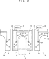
- Fig. 2 indicates the shelves 14.
- the shelf 14 is provided with a shelf support 18 having an opening 17; the transport apparatus 10 enters the arm, fork, or the like, into the opening 17 and transfers a FOUP 16 between the shelf 14.
- Each of the shelves 14 has three pins 19 and these pins 19 are coupled with grooves in the bottom of FOUP 16 and position the FOUP 16.
- a pair of or one purge nozzle 20 is provided and the purge nozzle 20 supplies clean gas such as nitrogen or clean dry air into a FOUP 16 supported on the shelf support 18.
- the shelf support 18 is further provided with a load sensor 21; the load sensor 21 detects whether a FOUP 16 is present or absent on the corresponding shelf 14.
- An MFC 22 (mass flow controller, an example of flow amount controlling device) supplies clean gas through a pipe 23 to the purge nozzle 20 (hereinafter, may be simply referred to as "nozzle 20" or “nozzle”).
- the shelf 14 may be provided further with an exhaust nozzle for evacuating the atmosphere in a FOUP 16, and so on in addition to the purge nozzle 20.
- an MFC 22 is provided for each shelf 14 so that the flow amount of clean gas from a nozzle 20 is controlled for each shelf 14.
- a common MFC 22 for a column or a row may be provided so that the total flow amount of clean gas for the column or the row is controlled.
- Fig. 3 indicates the control system for the purge stocker 2.
- a stocker controller 30 is the top-level controller in the purge stocker 2 and communicates with a transport controller 32 that controls the transport apparatus 6, in particular, the running motor 33, the elevation motor 34, and the transfer device10, and also with a purge controller 36 that controls the MFCs 22.
- the stocker controller 30 also communicates with an outside controller 38 and so on, and assigns a shelf 14 for an unloading position for an incoming FOUP 16, when informed that the incoming FOUP 16 shall be entered in. Further, when the incoming FOUP 16 arrives at an entrance and dispatch port, not shown in the drawings, the stocker controller 30 instructs the transport controller 32 to unload the incoming FOUP 16 on the shelf 14 designated as the unloading position.
- the stocker controller 30 determines a shelf 14 as the next unloading position, in advance and in preparation for the occurrence of a next incoming FOUP 16 to be entered, when the above unloading job of the incoming FOUP 16 is completed. Namely, the stocker controller 30 assigns in advance one shelf 14 for the next unloading position, in preparation for the storage of the next incoming FOUP 16.
- the stocker controller 30 designates, to the transport controller 32, the shelf 14 where the FOUP 16 to be dispatched is stored and instructs it to load the FOUP 16 at the designated shelf 14 and to transport to the entrance and dispatch port.
- a port for both entrance and dispatch may be provided, or an entrance port and a separate dispatch port may be provided.
- the stocker controller 30 has a memory that stores a file such as a shelf file 31; the memory stores the status of each shelf 14 comprising: "empty”, “empty but assigned for an incoming or next incoming container", "storing a container”, “storing a container assigned to dispatch”, etc.
- a file such as a shelf file 31
- the memory stores the status of each shelf 14 comprising: "empty”, “empty but assigned for an incoming or next incoming container", "storing a container”, “storing a container assigned to dispatch”, etc.
- Physically one controller may form all of the controllers 30, 32, and 36, or each of the controllers 30, 32, and 36 may comprise plural computers.
- the purge controller 36 controls the MFC 22 to carry out storage purge (purge for maintaining the cleanliness in a FOUP 16) when it detects that a FOUP 16 was unloaded on a shelf 14, by a signal from a load sensor 21. Further, when the purge controller 36 is informed, by the stocker controller 30, that a shelf 14 is assigned for a next incoming FOUP 16, before the actual occurrence of the next incoming FOUP 16 (immediately after the completion of a preceding entrance job), in preparation for the entrance job of the next incoming FOUP 16, the purge controller 36 carries out nozzle purge (purge for cleaning a nozzle 20) in the assigned shelf 14 so that the nozzle 20 in the assigned shelf 14 is cleaned.
- storage purge purge for maintaining the cleanliness in a FOUP 16
- the purge controller 36 when the purge controller 36 is informed, through the transport controller 32 and the stocker controller 30, that the arm, the fork, or the like of the transfer device 10 is advancing towards the shelf 14 for unloading, or the similar event, the purge controller 36 carries out bottom purge (purge for cleaning the bottom portion of a FOUP 16 facing a nozzle 20) for cleaning the bottom portion (inlet portion of clean gas in the bottom) of the incoming FOUP 16.
- the bottom purge may be omitted.
- the purge controller 36 may carry out the storage purge according to an information, via the stocker controller 30 from the transport controller 32, that the entrance job of the incoming FOUP 16 to the shelf 14 has been completed, rather than carrying out the storage purge according to the signal from the load sensor 21.
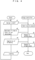
- Fig. 4 indicates the purge algorithm for a FOUP 16 according to the embodiment.
- the purge controller 36 starts the nozzle purge for the assigned shelf 14 (S1).
- the purge controller 36 changes the nozzle purge to the bottom purge (S2).
- the bottom purge may be omitted.
- the purge controller 36 may start the bottom purge.
- the purge controller 36 recognizes that the FOUP 16 has been unloaded on the shelf 14, by a signal from the load sensor 21, the transport controller 32, etc. (e3), the purge controller 36 carries out the storage purge (S3).
- the status of the shelf 14 returns to the empty status, and no further purge is necessary until it will be assigned for a next incoming FOUP.
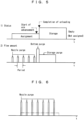
- Fig. 5 indicates a standard purge pattern.
- the purge controller 36 starts the nozzle purge for the assigned shelf 14.
- the nozzle purge is carried out intermittently; in other words, clean gas is repetitively discharged as pulses for a short duration from the nozzle 20.
- the solid line in Fig. 6 indicates the flow amount pattern of the clean gas according to the embodiment.
- the chain line in Fig. 6 indicates a constant flow amount pattern of the clean gas for the same total flow amount.
- the velocity of the clean gas is increased and the pressure around the nozzle 20 is fluctuated due to the on and off of the clean gas flow, and therefore, the nozzle is more efficiently cleaned than when the clean gas is discharged at a constant and small flow amount.
- the discharge duration and the discharge amount of the clean gas for one discharge pulse may be constant or not constant.
- the clean gas may be discharged for a relatively longer duration so that the nozzle 20 is cleaned and then, the clean gas may be repetitively discharged for relatively shorter duration for preventing the recontamination of the nozzle 20.
- the flow amount of the clean gas may be changed in such a way that, initially, at a relatively larger flow amount, the nozzle purge is performed and then the nozzle purge is performed at a relatively smaller flow amount.
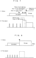
- the start of the advancement of the arm, the fork, or the like of the transfer device 10, and also the start of lowering of the arm, the fork, or the like, indicate the presence of a FOUP 16 over the shelf 14. Therefore, at the time when the arm, the fork, or the like of the transfer device 10 starts to advance, or at the time when they start to lower, clean gas is discharged, for example continuously, at a relatively larger flow amount from the nozzle 20.
- This process is called bottom purge, and its flow amount pattern is indicated in Fig. 7 .
- the bottom purge may be omitted.
- the discharge of clean gas from the nozzle 20 may be made on and off so that pulsation of clean gas flow is applied to the input valve and its neighborhood.
- the purge controller 36 carries out the storage purge that replaces the atmosphere in the FOUP 16 by clean gas.
- the purge controller 36 starts the purge of the nozzle 20, and therefore, the purge is carried out for an enough long duration.
- the purge controller 36 starts the purge of the nozzle 20, and therefore, the purge is carried out for an enough long duration.
- the intermittent nozzle purge makes the nozzle cleaner, efficiently with a small total flow amount.
- Fig. 9 indicates a clean gas flow amount pattern for one group of shelves according to a modification where plural shelves 14 are controlled as one group. This modification is suitable for a case where a common MFC 22 is provided for a column or a row of shelves as a unit.
- the purge controller 36 starts the nozzle purge in all shelves 14 within the group. Further, when the transport apparatus 6 starts the transfer of the FOUP 16 to the assigned shelf 14 for unloading, the purge controller 36 increases the flow amount of the clean gas so that the bottom portion of the FOUP 16 is purged.
- the stocker controller 30 assigns the empty shelf for a next incoming FOUP 16.
- the storage purge is carried out for the unloaded FOUP 16 so that the atmosphere in the FOUP 16 is substituted by the clean gas.
- the purge controller 36 restarts the nozzle purge.
- Fig. 10 indicates an embodiment where an overhead transport system is used as the storage system.
- a plurality of overhead transport vehicles 42 run, and there are provided a plurality of buffers 44 for storing temporarily FOUPs, along the running rail 40.
- the buffers 44 may have one or plural shelves 45 per buffer.
- a system controller 46 controls the entire overhead transport system, communicates with an outside controller, and receives transport requests of FOUPs from the outside controller.
- the buffer 44 is provided with a nozzle 20 in each shelf 45, and a purge controller 48 controls an MFC 22 so as to regulate the supply of clean gas to the nozzle 20.
- the system controller 46 assigns an empty buffer 44 for temporarily storing a FOUP in advance, when it is required to transport a FOUP from an outside controller, or spontaneously without waiting for the request from the outside controller. Then, the system controller 46 instructs the purge controller 48 in the assigned empty buffer 44 to start the nozzle purge. Further, if the entrance of a transfer device of an overhead transport vehicle 42 over the shelf 45 is detectable, the purge controller 48 carries out the bottom purge.
Landscapes
- Engineering & Computer Science (AREA)
- Mechanical Engineering (AREA)
- Container, Conveyance, Adherence, Positioning, Of Wafer (AREA)
- Warehouses Or Storage Devices (AREA)
Claims (8)
- Système de stockage comprenant:une pluralité d'étagères (14) pourvues respectivement d'au moins une buse (20) configurée pour alimenter du gaz propre vers les conteneurs (16);une pluralité de dispositifs de commande de quantité de flux (22) configurés respectivement pour commander la quantité d'alimentation dudit gaz propre vers ladite au moins une buse (20);au moins un appareil de transport (6) configuré pour transférer lesdits conteneurs (16) vers et depuis lesdites étagères (14); etun moyen de commande (30, 32, 36) configuré pour commander ledit au moins un appareil de transport (6) et lesdits dispositifs de commande de quantité de flux (22),dans lequel ledit moyen de commande (30, 32, 36) est configuré et programmépour décharger un conteneur entrant (16) sur une étagère (14) de la pluralité d'étagères (14) à une position de déchargement,pour effectuer une attribution d'au moins une étagère (14) en préparation pour le stockage d'un conteneur entrant suivant (16) immédiatement après que soit terminé le déchargement du conteneur entrant (16) et avant l'apparition dudit conteneur entrant suivant (16), etpour commander l'un desdits dispositifs de commande de quantité de flux (22) pour alimenter ledit gaz propre vers ladite au moins une buse (20) dans ladite au moins une étagère (14), sur base de ladite attribution,dans lequel l'alimentation de gaz propre est commencée lorsque l'attribution de l'étagère pour le conteneur entrant suivant (16) est effectuée et avant l'apparition dudit conteneur entrant suivant (16).
- Système de stockage selon la revendication 1, dans lequel ledit système de stockage est un stockeur à purge (2) et est par ailleurs pourvu d'un orifice d'entrée et d'acheminement,dans lequel ledit au moins un appareil de transport (6) est configuré pour transporter lesdits conteneurs (16) entre ledit orifice d'entrée et d'acheminement et lesdites étagères (14), etdans lequel ledit moyen de commande (30) est par ailleurs configuré et programmé pour effectuer ladite attribution de ladite au moins une étagère (14) à l'avance, avant que ledit conteneur entrant (16) n'arrive audit orifice d'entrée et d'acheminement.
- Système de stockage selon la revendication 1 ou 2, dans lequel ledit moyen de commande (36) est par ailleurs configuré et programmé pour commander ledit un desdits dispositifs de commande de quantité de flux (22) pour alimenter par intermittence ledit gaz propre vers ladite au moins une buse (20) dans ladite au moins une étagère (14).
- Système de stockage selon l'une des revendications 1 à 3, dans lequel ledit au moins un appareil de transport (6) est pourvu d'un dispositif de transfert (10) configuré pour entrer dans et décharger ledit conteneur entrant (16) sur lesdites étagères (14), et
dans lequel ledit moyen de commande (36) est par ailleurs configuré et programmé pour commander ledit un desdits dispositifs de commande de quantité de flux (22) pour alimenter une quantité de flux plus grande dudit gaz propre vers ladite au moins une buse (20), à partir du moment où ledit dispositif de transfert (6) commence à avancer vers ladite au moins une étagère (14) et jusqu'à ce que soit terminé le déchargement dudit conteneur entrant (16), qu'une quantité avant que ledit dispositif de transfert (6) ne commence à avancer. - Système de stockage selon la revendication 4, dans lequel ledit moyen de commande (36) est par ailleurs configuré pour effectuer une purge de stockage pour maintenir la propreté dans un conteneur lorsque le moyen de commande (36) reconnaît que le conteneur (16) a été déchargé sur l'étagère (14).
- Procédé de purge dans un système de stockage comprenant: une pluralité d'étagères (14) pourvues respectivement d'au moins une buse (20) pour alimenter du gaz propre vers des conteneurs (16); une pluralité de dispositifs de commande de quantité de flux (22) commandant respectivement la quantité d'alimentation dudit gaz propre vers ladite au moins une buse (20); au moins un appareil de transport (6) transférant lesdits conteneurs (16) vers et depuis lesdites étagères (14); et un moyen de commande (30, 32, 36) commandant ledit au moins un appareil de transport (6) et lesdits dispositifs de commande de quantité de flux (22), ledit procédé comprenant le fait de:décharger un conteneur entrant (16) sur une étagère (14) de la pluralité d'étagères (14) à une position de déchargement,effectuer une attribution d'au moins une étagère (14) en préparation pour le stockage d'un conteneur entrant suivant (16) immédiatement après que soit terminé le déchargement du conteneur entrant (16) et avant l'apparition dudit conteneur entrant suivant (16), par ledit moyen de commande (30), etalimenter ledit gaz propre vers ladite au moins une buse (20) dans ladite au moins une étagère (14), sur base de ladite attribution,dans lequel l'alimentation de gaz propre est commencée lorsque l'attribution de l'étagère pour le conteneur entrant suivant (16) est effectuée et avant l'apparition dudit conteneur entrant suivant (16).
- Procédé de purge selon la revendication 6, dans lequel ledit au moins un appareil de transport (6) est pourvu d'un dispositif de transfert (10) configuré pour entrer dans et décharger ledit conteneur entrant (16) sur lesdites étagères (14), dans lequel ledit le procédé comprend par ailleurs le fait de, par ledit moyen de commande (36), commander ledit un desdits dispositifs de commande de quantité de flux (22) pour alimenter une quantité de flux plus grande dudit gaz propre vers ladite au moins une buse (20), à partir du moment où ledit dispositif de transfert (6) commence à avancer vers ladite au moins une étagère (14) et jusqu'à ce que soit terminé le déchargement dudit conteneur entrant (16), qu'une quantité avant que ledit dispositif de transfert (6) ne commence à avancer.
- Procédé de purge selon la revendication 7, comprenant par ailleurs le fait de, par ledit moyen de commande (36), effectuer une purge de stockage pour maintenir la propreté dans un conteneur lorsque le moyen de commande (36) reconnaît que le conteneur (16) a été déchargé sur l'étagère (14).
Applications Claiming Priority (2)
| Application Number | Priority Date | Filing Date | Title |
|---|---|---|---|
| JP2017172888 | 2017-09-08 | ||
| PCT/JP2018/027043 WO2019049518A1 (fr) | 2017-09-08 | 2018-07-19 | Système de stockage et procédé de purge dans un système de stockage |
Publications (3)
| Publication Number | Publication Date |
|---|---|
| EP3680930A1 EP3680930A1 (fr) | 2020-07-15 |
| EP3680930A4 EP3680930A4 (fr) | 2021-06-02 |
| EP3680930B1 true EP3680930B1 (fr) | 2023-12-27 |
Family
ID=65633756
Family Applications (1)
| Application Number | Title | Priority Date | Filing Date |
|---|---|---|---|
| EP18854967.9A Active EP3680930B1 (fr) | 2017-09-08 | 2018-07-19 | Système de stockage et procédé de purge dans un système de stockage |
Country Status (9)
| Country | Link |
|---|---|
| US (1) | US11608229B2 (fr) |
| EP (1) | EP3680930B1 (fr) |
| JP (1) | JP6813097B2 (fr) |
| KR (1) | KR102391970B1 (fr) |
| CN (1) | CN111052338B (fr) |
| IL (1) | IL272426B (fr) |
| SG (1) | SG11202001780UA (fr) |
| TW (1) | TWI749256B (fr) |
| WO (1) | WO2019049518A1 (fr) |
Families Citing this family (7)
| Publication number | Priority date | Publication date | Assignee | Title |
|---|---|---|---|---|
| JP7067621B2 (ja) * | 2018-07-20 | 2022-05-16 | 村田機械株式会社 | 保管棚及び保管棚の設置方法 |
| CN110745449A (zh) * | 2019-10-18 | 2020-02-04 | 艾信智慧医疗科技发展(苏州)有限公司 | 智能货柜的控制方法及智能货柜 |
| KR102627684B1 (ko) * | 2019-11-05 | 2024-01-23 | 무라다기카이가부시끼가이샤 | 반송차 시스템 |
| KR102663006B1 (ko) * | 2020-09-07 | 2024-05-02 | 세메스 주식회사 | 용기 보관 장치 및 방법 |
| CN117461122A (zh) * | 2021-10-01 | 2024-01-26 | 村田机械株式会社 | 净化装置 |
| WO2023076156A1 (fr) * | 2021-10-27 | 2023-05-04 | Entegris, Inc. | Procédé et dispositif de régulation de purge dans un récipient |
| JP7834231B1 (ja) * | 2025-11-27 | 2026-03-23 | 平田機工株式会社 | 容器保管装置及び保管方法 |
Citations (2)
| Publication number | Priority date | Publication date | Assignee | Title |
|---|---|---|---|---|
| US9245781B2 (en) * | 2012-01-04 | 2016-01-26 | Daifuku Co., Ltd. | Article storage facility and article storage method |
| JP2016218603A (ja) * | 2015-05-18 | 2016-12-22 | 村田機械株式会社 | 流量制御装置、パージ装置、及びパージストッカ |
Family Cites Families (21)
| Publication number | Priority date | Publication date | Assignee | Title |
|---|---|---|---|---|
| JPH07130831A (ja) * | 1993-10-28 | 1995-05-19 | Nippon Steel Corp | 半導体ウエハの収納・搬送装置 |
| TW491802B (en) | 2001-05-21 | 2002-06-21 | Taiwan Semiconductor Mfg | Automated material handling method basing on adaptability control |
| US6899145B2 (en) * | 2003-03-20 | 2005-05-31 | Asm America, Inc. | Front opening unified pod |
| JP4027837B2 (ja) * | 2003-04-28 | 2007-12-26 | Tdk株式会社 | パージ装置およびパージ方法 |
| JP4012190B2 (ja) * | 2004-10-26 | 2007-11-21 | Tdk株式会社 | 密閉容器の蓋開閉システム及び開閉方法 |
| JP4692584B2 (ja) | 2008-07-03 | 2011-06-01 | 村田機械株式会社 | パージ装置 |
| JP5381054B2 (ja) * | 2008-12-02 | 2014-01-08 | シンフォニアテクノロジー株式会社 | ロードポート |
| JP5236518B2 (ja) * | 2009-02-03 | 2013-07-17 | 株式会社ダン・タクマ | 保管システムおよび保管方法 |
| JP2012094822A (ja) * | 2010-09-30 | 2012-05-17 | Shibaura Mechatronics Corp | 密閉型容器及び半導体製造装置 |
| JP5887719B2 (ja) * | 2011-05-31 | 2016-03-16 | シンフォニアテクノロジー株式会社 | パージ装置、ロードポート、ボトムパージノズル本体、ボトムパージユニット |
| JP5366030B2 (ja) * | 2011-09-22 | 2013-12-11 | 村田機械株式会社 | クリーンルーム用の自動倉庫 |
| KR101147192B1 (ko) * | 2011-11-11 | 2012-05-25 | 주식회사 엘에스테크 | 웨이퍼 표면상의 증착 이물 제거 장치 |
| JP5598728B2 (ja) * | 2011-12-22 | 2014-10-01 | 株式会社ダイフク | 不活性ガス注入装置 |
| JP5716968B2 (ja) * | 2012-01-04 | 2015-05-13 | 株式会社ダイフク | 物品保管設備 |
| JP5884780B2 (ja) * | 2013-06-26 | 2016-03-15 | 株式会社ダイフク | 保管設備 |
| JP5884779B2 (ja) * | 2013-06-26 | 2016-03-15 | 株式会社ダイフク | 物品保管設備 |
| US10325794B2 (en) * | 2014-04-28 | 2019-06-18 | Murata Machinery, Ltd. | Purge device and purge method |
| JP2016054240A (ja) * | 2014-09-04 | 2016-04-14 | 村田機械株式会社 | ストッカ |
| JP6459682B2 (ja) * | 2015-03-20 | 2019-01-30 | Tdk株式会社 | ガスパージ装置、ロードポート装置およびガスパージ方法 |
| WO2017026168A1 (fr) * | 2015-08-10 | 2017-02-16 | 村田機械株式会社 | Dispositif de purge, dispositif de stockage de purge et procédé de nettoyage |
| EP3343596B1 (fr) | 2015-08-25 | 2022-01-12 | Murata Machinery, Ltd. | Dispositif de purge, dispositif d'emmagasinement de purge et procédé de purge |
-
2018
- 2018-07-19 CN CN201880055618.4A patent/CN111052338B/zh active Active
- 2018-07-19 EP EP18854967.9A patent/EP3680930B1/fr active Active
- 2018-07-19 WO PCT/JP2018/027043 patent/WO2019049518A1/fr not_active Ceased
- 2018-07-19 US US16/642,084 patent/US11608229B2/en active Active
- 2018-07-19 KR KR1020207009152A patent/KR102391970B1/ko active Active
- 2018-07-19 SG SG11202001780UA patent/SG11202001780UA/en unknown
- 2018-07-19 JP JP2019540805A patent/JP6813097B2/ja active Active
- 2018-09-03 TW TW107130851A patent/TWI749256B/zh active
-
2020
- 2020-02-02 IL IL272426A patent/IL272426B/en active IP Right Grant
Patent Citations (2)
| Publication number | Priority date | Publication date | Assignee | Title |
|---|---|---|---|---|
| US9245781B2 (en) * | 2012-01-04 | 2016-01-26 | Daifuku Co., Ltd. | Article storage facility and article storage method |
| JP2016218603A (ja) * | 2015-05-18 | 2016-12-22 | 村田機械株式会社 | 流量制御装置、パージ装置、及びパージストッカ |
Also Published As
| Publication number | Publication date |
|---|---|
| KR20200047639A (ko) | 2020-05-07 |
| JP6813097B2 (ja) | 2021-01-13 |
| KR102391970B1 (ko) | 2022-04-28 |
| IL272426A (en) | 2020-03-31 |
| SG11202001780UA (en) | 2020-03-30 |
| IL272426B (en) | 2020-09-30 |
| EP3680930A1 (fr) | 2020-07-15 |
| EP3680930A4 (fr) | 2021-06-02 |
| WO2019049518A1 (fr) | 2019-03-14 |
| JPWO2019049518A1 (ja) | 2020-08-13 |
| TWI749256B (zh) | 2021-12-11 |
| TW201936465A (zh) | 2019-09-16 |
| CN111052338A (zh) | 2020-04-21 |
| US11608229B2 (en) | 2023-03-21 |
| CN111052338B (zh) | 2023-06-30 |
| US20200180864A1 (en) | 2020-06-11 |
Similar Documents
| Publication | Publication Date | Title |
|---|---|---|
| EP3680930B1 (fr) | Système de stockage et procédé de purge dans un système de stockage | |
| US9701431B2 (en) | Load port device, transport system, and container carrying out method | |
| EP3200221B1 (fr) | Dispositif et procédé de purge | |
| CN107924857B (zh) | 保管装置和保管方法 | |
| TWI647017B (zh) | Purification device, purification system, purification method and control method of purification system | |
| CN107534004B (zh) | 清洗堆料机以及清洗方法 | |
| JP2968742B2 (ja) | 自動保管棚及び自動保管方法 | |
| CN108352349A (zh) | 输送系统和输送方法 | |
| JP6152843B2 (ja) | バッファシステム及び物品のバッファ方法 | |
| JP4657528B2 (ja) | 処理システムおよび処理方法 | |
| JP2002110766A (ja) | 搬送システム及び搬送方法 | |
| JP2008100801A (ja) | 基板保管庫 |
Legal Events
| Date | Code | Title | Description |
|---|---|---|---|
| STAA | Information on the status of an ep patent application or granted ep patent |
Free format text: STATUS: THE INTERNATIONAL PUBLICATION HAS BEEN MADE |
|
| PUAI | Public reference made under article 153(3) epc to a published international application that has entered the european phase |
Free format text: ORIGINAL CODE: 0009012 |
|
| STAA | Information on the status of an ep patent application or granted ep patent |
Free format text: STATUS: REQUEST FOR EXAMINATION WAS MADE |
|
| 17P | Request for examination filed |
Effective date: 20200403 |
|
| AK | Designated contracting states |
Kind code of ref document: A1 Designated state(s): AL AT BE BG CH CY CZ DE DK EE ES FI FR GB GR HR HU IE IS IT LI LT LU LV MC MK MT NL NO PL PT RO RS SE SI SK SM TR |
|
| AX | Request for extension of the european patent |
Extension state: BA ME |
|
| DAV | Request for validation of the european patent (deleted) | ||
| DAX | Request for extension of the european patent (deleted) | ||
| A4 | Supplementary search report drawn up and despatched |
Effective date: 20210430 |
|
| RIC1 | Information provided on ipc code assigned before grant |
Ipc: H01L 21/677 20060101AFI20210423BHEP Ipc: B65G 1/00 20060101ALI20210423BHEP Ipc: B65G 1/137 20060101ALI20210423BHEP Ipc: H01L 21/673 20060101ALI20210423BHEP Ipc: B65G 1/02 20060101ALI20210423BHEP |
|
| STAA | Information on the status of an ep patent application or granted ep patent |
Free format text: STATUS: EXAMINATION IS IN PROGRESS |
|
| 17Q | First examination report despatched |
Effective date: 20221102 |
|
| GRAP | Despatch of communication of intention to grant a patent |
Free format text: ORIGINAL CODE: EPIDOSNIGR1 |
|
| STAA | Information on the status of an ep patent application or granted ep patent |
Free format text: STATUS: GRANT OF PATENT IS INTENDED |
|
| INTG | Intention to grant announced |
Effective date: 20230710 |
|
| RIN1 | Information on inventor provided before grant (corrected) |
Inventor name: YAMAJI, TAKASHI Inventor name: TSUBAKI, TATSUO |
|
| GRAS | Grant fee paid |
Free format text: ORIGINAL CODE: EPIDOSNIGR3 |
|
| GRAA | (expected) grant |
Free format text: ORIGINAL CODE: 0009210 |
|
| STAA | Information on the status of an ep patent application or granted ep patent |
Free format text: STATUS: THE PATENT HAS BEEN GRANTED |
|
| AK | Designated contracting states |
Kind code of ref document: B1 Designated state(s): AL AT BE BG CH CY CZ DE DK EE ES FI FR GB GR HR HU IE IS IT LI LT LU LV MC MK MT NL NO PL PT RO RS SE SI SK SM TR |
|
| REG | Reference to a national code |
Ref country code: GB Ref legal event code: FG4D |
|
| REG | Reference to a national code |
Ref country code: CH Ref legal event code: EP |
|
| REG | Reference to a national code |
Ref country code: DE Ref legal event code: R096 Ref document number: 602018063367 Country of ref document: DE |
|
| REG | Reference to a national code |
Ref country code: IE Ref legal event code: FG4D |
|
| PG25 | Lapsed in a contracting state [announced via postgrant information from national office to epo] |
Ref country code: GR Free format text: LAPSE BECAUSE OF FAILURE TO SUBMIT A TRANSLATION OF THE DESCRIPTION OR TO PAY THE FEE WITHIN THE PRESCRIBED TIME-LIMIT Effective date: 20240328 |
|
| REG | Reference to a national code |
Ref country code: LT Ref legal event code: MG9D |
|
| PG25 | Lapsed in a contracting state [announced via postgrant information from national office to epo] |
Ref country code: LT Free format text: LAPSE BECAUSE OF FAILURE TO SUBMIT A TRANSLATION OF THE DESCRIPTION OR TO PAY THE FEE WITHIN THE PRESCRIBED TIME-LIMIT Effective date: 20231227 |
|
| PG25 | Lapsed in a contracting state [announced via postgrant information from national office to epo] |
Ref country code: ES Free format text: LAPSE BECAUSE OF FAILURE TO SUBMIT A TRANSLATION OF THE DESCRIPTION OR TO PAY THE FEE WITHIN THE PRESCRIBED TIME-LIMIT Effective date: 20231227 |
|
| PG25 | Lapsed in a contracting state [announced via postgrant information from national office to epo] |
Ref country code: LT Free format text: LAPSE BECAUSE OF FAILURE TO SUBMIT A TRANSLATION OF THE DESCRIPTION OR TO PAY THE FEE WITHIN THE PRESCRIBED TIME-LIMIT Effective date: 20231227 Ref country code: GR Free format text: LAPSE BECAUSE OF FAILURE TO SUBMIT A TRANSLATION OF THE DESCRIPTION OR TO PAY THE FEE WITHIN THE PRESCRIBED TIME-LIMIT Effective date: 20240328 Ref country code: FI Free format text: LAPSE BECAUSE OF FAILURE TO SUBMIT A TRANSLATION OF THE DESCRIPTION OR TO PAY THE FEE WITHIN THE PRESCRIBED TIME-LIMIT Effective date: 20231227 Ref country code: ES Free format text: LAPSE BECAUSE OF FAILURE TO SUBMIT A TRANSLATION OF THE DESCRIPTION OR TO PAY THE FEE WITHIN THE PRESCRIBED TIME-LIMIT Effective date: 20231227 Ref country code: BG Free format text: LAPSE BECAUSE OF FAILURE TO SUBMIT A TRANSLATION OF THE DESCRIPTION OR TO PAY THE FEE WITHIN THE PRESCRIBED TIME-LIMIT Effective date: 20240327 |
|
| REG | Reference to a national code |
Ref country code: NL Ref legal event code: MP Effective date: 20231227 |
|
| REG | Reference to a national code |
Ref country code: AT Ref legal event code: MK05 Ref document number: 1645352 Country of ref document: AT Kind code of ref document: T Effective date: 20231227 |
|
| PG25 | Lapsed in a contracting state [announced via postgrant information from national office to epo] |
Ref country code: NL Free format text: LAPSE BECAUSE OF FAILURE TO SUBMIT A TRANSLATION OF THE DESCRIPTION OR TO PAY THE FEE WITHIN THE PRESCRIBED TIME-LIMIT Effective date: 20231227 |
|
| PG25 | Lapsed in a contracting state [announced via postgrant information from national office to epo] |
Ref country code: SE Free format text: LAPSE BECAUSE OF FAILURE TO SUBMIT A TRANSLATION OF THE DESCRIPTION OR TO PAY THE FEE WITHIN THE PRESCRIBED TIME-LIMIT Effective date: 20231227 Ref country code: RS Free format text: LAPSE BECAUSE OF FAILURE TO SUBMIT A TRANSLATION OF THE DESCRIPTION OR TO PAY THE FEE WITHIN THE PRESCRIBED TIME-LIMIT Effective date: 20231227 Ref country code: NO Free format text: LAPSE BECAUSE OF FAILURE TO SUBMIT A TRANSLATION OF THE DESCRIPTION OR TO PAY THE FEE WITHIN THE PRESCRIBED TIME-LIMIT Effective date: 20240327 Ref country code: NL Free format text: LAPSE BECAUSE OF FAILURE TO SUBMIT A TRANSLATION OF THE DESCRIPTION OR TO PAY THE FEE WITHIN THE PRESCRIBED TIME-LIMIT Effective date: 20231227 Ref country code: LV Free format text: LAPSE BECAUSE OF FAILURE TO SUBMIT A TRANSLATION OF THE DESCRIPTION OR TO PAY THE FEE WITHIN THE PRESCRIBED TIME-LIMIT Effective date: 20231227 Ref country code: HR Free format text: LAPSE BECAUSE OF FAILURE TO SUBMIT A TRANSLATION OF THE DESCRIPTION OR TO PAY THE FEE WITHIN THE PRESCRIBED TIME-LIMIT Effective date: 20231227 |
|
| PG25 | Lapsed in a contracting state [announced via postgrant information from national office to epo] |
Ref country code: IS Free format text: LAPSE BECAUSE OF FAILURE TO SUBMIT A TRANSLATION OF THE DESCRIPTION OR TO PAY THE FEE WITHIN THE PRESCRIBED TIME-LIMIT Effective date: 20240427 |
|
| PG25 | Lapsed in a contracting state [announced via postgrant information from national office to epo] |
Ref country code: AT Free format text: LAPSE BECAUSE OF FAILURE TO SUBMIT A TRANSLATION OF THE DESCRIPTION OR TO PAY THE FEE WITHIN THE PRESCRIBED TIME-LIMIT Effective date: 20231227 Ref country code: CZ Free format text: LAPSE BECAUSE OF FAILURE TO SUBMIT A TRANSLATION OF THE DESCRIPTION OR TO PAY THE FEE WITHIN THE PRESCRIBED TIME-LIMIT Effective date: 20231227 |
|
| PG25 | Lapsed in a contracting state [announced via postgrant information from national office to epo] |
Ref country code: SK Free format text: LAPSE BECAUSE OF FAILURE TO SUBMIT A TRANSLATION OF THE DESCRIPTION OR TO PAY THE FEE WITHIN THE PRESCRIBED TIME-LIMIT Effective date: 20231227 |
|
| PG25 | Lapsed in a contracting state [announced via postgrant information from national office to epo] |
Ref country code: SM Free format text: LAPSE BECAUSE OF FAILURE TO SUBMIT A TRANSLATION OF THE DESCRIPTION OR TO PAY THE FEE WITHIN THE PRESCRIBED TIME-LIMIT Effective date: 20231227 Ref country code: SK Free format text: LAPSE BECAUSE OF FAILURE TO SUBMIT A TRANSLATION OF THE DESCRIPTION OR TO PAY THE FEE WITHIN THE PRESCRIBED TIME-LIMIT Effective date: 20231227 Ref country code: RO Free format text: LAPSE BECAUSE OF FAILURE TO SUBMIT A TRANSLATION OF THE DESCRIPTION OR TO PAY THE FEE WITHIN THE PRESCRIBED TIME-LIMIT Effective date: 20231227 Ref country code: IT Free format text: LAPSE BECAUSE OF FAILURE TO SUBMIT A TRANSLATION OF THE DESCRIPTION OR TO PAY THE FEE WITHIN THE PRESCRIBED TIME-LIMIT Effective date: 20231227 Ref country code: IS Free format text: LAPSE BECAUSE OF FAILURE TO SUBMIT A TRANSLATION OF THE DESCRIPTION OR TO PAY THE FEE WITHIN THE PRESCRIBED TIME-LIMIT Effective date: 20240427 Ref country code: EE Free format text: LAPSE BECAUSE OF FAILURE TO SUBMIT A TRANSLATION OF THE DESCRIPTION OR TO PAY THE FEE WITHIN THE PRESCRIBED TIME-LIMIT Effective date: 20231227 Ref country code: CZ Free format text: LAPSE BECAUSE OF FAILURE TO SUBMIT A TRANSLATION OF THE DESCRIPTION OR TO PAY THE FEE WITHIN THE PRESCRIBED TIME-LIMIT Effective date: 20231227 Ref country code: AT Free format text: LAPSE BECAUSE OF FAILURE TO SUBMIT A TRANSLATION OF THE DESCRIPTION OR TO PAY THE FEE WITHIN THE PRESCRIBED TIME-LIMIT Effective date: 20231227 |
|
| PG25 | Lapsed in a contracting state [announced via postgrant information from national office to epo] |
Ref country code: PL Free format text: LAPSE BECAUSE OF FAILURE TO SUBMIT A TRANSLATION OF THE DESCRIPTION OR TO PAY THE FEE WITHIN THE PRESCRIBED TIME-LIMIT Effective date: 20231227 Ref country code: PT Free format text: LAPSE BECAUSE OF FAILURE TO SUBMIT A TRANSLATION OF THE DESCRIPTION OR TO PAY THE FEE WITHIN THE PRESCRIBED TIME-LIMIT Effective date: 20240429 |
|
| PG25 | Lapsed in a contracting state [announced via postgrant information from national office to epo] |
Ref country code: PT Free format text: LAPSE BECAUSE OF FAILURE TO SUBMIT A TRANSLATION OF THE DESCRIPTION OR TO PAY THE FEE WITHIN THE PRESCRIBED TIME-LIMIT Effective date: 20240429 Ref country code: PL Free format text: LAPSE BECAUSE OF FAILURE TO SUBMIT A TRANSLATION OF THE DESCRIPTION OR TO PAY THE FEE WITHIN THE PRESCRIBED TIME-LIMIT Effective date: 20231227 |
|
| REG | Reference to a national code |
Ref country code: DE Ref legal event code: R097 Ref document number: 602018063367 Country of ref document: DE |
|
| PG25 | Lapsed in a contracting state [announced via postgrant information from national office to epo] |
Ref country code: DK Free format text: LAPSE BECAUSE OF FAILURE TO SUBMIT A TRANSLATION OF THE DESCRIPTION OR TO PAY THE FEE WITHIN THE PRESCRIBED TIME-LIMIT Effective date: 20231227 |
|
| PG25 | Lapsed in a contracting state [announced via postgrant information from national office to epo] |
Ref country code: DK Free format text: LAPSE BECAUSE OF FAILURE TO SUBMIT A TRANSLATION OF THE DESCRIPTION OR TO PAY THE FEE WITHIN THE PRESCRIBED TIME-LIMIT Effective date: 20231227 |
|
| PLBE | No opposition filed within time limit |
Free format text: ORIGINAL CODE: 0009261 |
|
| STAA | Information on the status of an ep patent application or granted ep patent |
Free format text: STATUS: NO OPPOSITION FILED WITHIN TIME LIMIT |
|
| 26N | No opposition filed |
Effective date: 20240930 |
|
| PG25 | Lapsed in a contracting state [announced via postgrant information from national office to epo] |
Ref country code: MC Free format text: LAPSE BECAUSE OF FAILURE TO SUBMIT A TRANSLATION OF THE DESCRIPTION OR TO PAY THE FEE WITHIN THE PRESCRIBED TIME-LIMIT Effective date: 20231227 |
|
| REG | Reference to a national code |
Ref country code: CH Ref legal event code: PL |
|
| PG25 | Lapsed in a contracting state [announced via postgrant information from national office to epo] |
Ref country code: LU Free format text: LAPSE BECAUSE OF NON-PAYMENT OF DUE FEES Effective date: 20240719 |
|
| GBPC | Gb: european patent ceased through non-payment of renewal fee |
Effective date: 20240719 |
|
| PG25 | Lapsed in a contracting state [announced via postgrant information from national office to epo] |
Ref country code: LU Free format text: LAPSE BECAUSE OF NON-PAYMENT OF DUE FEES Effective date: 20240719 |
|
| PG25 | Lapsed in a contracting state [announced via postgrant information from national office to epo] |
Ref country code: CH Free format text: LAPSE BECAUSE OF NON-PAYMENT OF DUE FEES Effective date: 20240731 Ref country code: BE Free format text: LAPSE BECAUSE OF NON-PAYMENT OF DUE FEES Effective date: 20240731 Ref country code: SI Free format text: LAPSE BECAUSE OF FAILURE TO SUBMIT A TRANSLATION OF THE DESCRIPTION OR TO PAY THE FEE WITHIN THE PRESCRIBED TIME-LIMIT Effective date: 20231227 |
|
| PG25 | Lapsed in a contracting state [announced via postgrant information from national office to epo] |
Ref country code: FR Free format text: LAPSE BECAUSE OF NON-PAYMENT OF DUE FEES Effective date: 20240731 |
|
| PG25 | Lapsed in a contracting state [announced via postgrant information from national office to epo] |
Ref country code: GB Free format text: LAPSE BECAUSE OF NON-PAYMENT OF DUE FEES Effective date: 20240719 |
|
| REG | Reference to a national code |
Ref country code: BE Ref legal event code: MM Effective date: 20240731 |
|
| PGFP | Annual fee paid to national office [announced via postgrant information from national office to epo] |
Ref country code: IE Payment date: 20250623 Year of fee payment: 8 |
|
| PGFP | Annual fee paid to national office [announced via postgrant information from national office to epo] |
Ref country code: DE Payment date: 20250620 Year of fee payment: 8 |
|
| PG25 | Lapsed in a contracting state [announced via postgrant information from national office to epo] |
Ref country code: CY Free format text: LAPSE BECAUSE OF FAILURE TO SUBMIT A TRANSLATION OF THE DESCRIPTION OR TO PAY THE FEE WITHIN THE PRESCRIBED TIME-LIMIT; INVALID AB INITIO Effective date: 20180719 |
|
| REG | Reference to a national code |
Ref country code: DE Ref legal event code: R079 Ref document number: 602018063367 Country of ref document: DE Free format text: PREVIOUS MAIN CLASS: H01L0021677000 Ipc: H10P0072300000 |
|
| PG25 | Lapsed in a contracting state [announced via postgrant information from national office to epo] |
Ref country code: HU Free format text: LAPSE BECAUSE OF FAILURE TO SUBMIT A TRANSLATION OF THE DESCRIPTION OR TO PAY THE FEE WITHIN THE PRESCRIBED TIME-LIMIT; INVALID AB INITIO Effective date: 20180719 |