EP3680997A1 - Method and construction kit system for producing a connector by selecting an insert element - Google Patents
Method and construction kit system for producing a connector by selecting an insert element Download PDFInfo
- Publication number
- EP3680997A1 EP3680997A1 EP20150658.1A EP20150658A EP3680997A1 EP 3680997 A1 EP3680997 A1 EP 3680997A1 EP 20150658 A EP20150658 A EP 20150658A EP 3680997 A1 EP3680997 A1 EP 3680997A1
- Authority
- EP
- European Patent Office
- Prior art keywords
- housing
- insert
- connector
- plug
- insert element
- Prior art date
- Legal status (The legal status is an assumption and is not a legal conclusion. Google has not performed a legal analysis and makes no representation as to the accuracy of the status listed.)
- Granted
Links
Images

Classifications
-
- H—ELECTRICITY
- H01—ELECTRIC ELEMENTS
- H01R—ELECTRICALLY-CONDUCTIVE CONNECTIONS; STRUCTURAL ASSOCIATIONS OF A PLURALITY OF MUTUALLY-INSULATED ELECTRICAL CONNECTING ELEMENTS; COUPLING DEVICES; CURRENT COLLECTORS
- H01R43/00—Apparatus or processes specially adapted for manufacturing, assembling, maintaining, or repairing of line connectors or current collectors or for joining electric conductors
- H01R43/18—Apparatus or processes specially adapted for manufacturing, assembling, maintaining, or repairing of line connectors or current collectors or for joining electric conductors for manufacturing bases or cases for contact members
-
- H—ELECTRICITY
- H01—ELECTRIC ELEMENTS
- H01R—ELECTRICALLY-CONDUCTIVE CONNECTIONS; STRUCTURAL ASSOCIATIONS OF A PLURALITY OF MUTUALLY-INSULATED ELECTRICAL CONNECTING ELEMENTS; COUPLING DEVICES; CURRENT COLLECTORS
- H01R13/00—Details of coupling devices of the kinds covered by groups H01R12/70 or H01R24/00 - H01R33/00
- H01R13/02—Contact members
-
- H—ELECTRICITY
- H01—ELECTRIC ELEMENTS
- H01R—ELECTRICALLY-CONDUCTIVE CONNECTIONS; STRUCTURAL ASSOCIATIONS OF A PLURALITY OF MUTUALLY-INSULATED ELECTRICAL CONNECTING ELEMENTS; COUPLING DEVICES; CURRENT COLLECTORS
- H01R13/00—Details of coupling devices of the kinds covered by groups H01R12/70 or H01R24/00 - H01R33/00
- H01R13/46—Bases; Cases
- H01R13/502—Bases; Cases composed of different pieces
-
- H—ELECTRICITY
- H01—ELECTRIC ELEMENTS
- H01R—ELECTRICALLY-CONDUCTIVE CONNECTIONS; STRUCTURAL ASSOCIATIONS OF A PLURALITY OF MUTUALLY-INSULATED ELECTRICAL CONNECTING ELEMENTS; COUPLING DEVICES; CURRENT COLLECTORS
- H01R13/00—Details of coupling devices of the kinds covered by groups H01R12/70 or H01R24/00 - H01R33/00
- H01R13/46—Bases; Cases
- H01R13/502—Bases; Cases composed of different pieces
- H01R13/504—Bases; Cases composed of different pieces different pieces being moulded, cemented, welded, e.g. ultrasonic welding, or swaged together
-
- H—ELECTRICITY
- H01—ELECTRIC ELEMENTS
- H01R—ELECTRICALLY-CONDUCTIVE CONNECTIONS; STRUCTURAL ASSOCIATIONS OF A PLURALITY OF MUTUALLY-INSULATED ELECTRICAL CONNECTING ELEMENTS; COUPLING DEVICES; CURRENT COLLECTORS
- H01R43/00—Apparatus or processes specially adapted for manufacturing, assembling, maintaining, or repairing of line connectors or current collectors or for joining electric conductors
- H01R43/20—Apparatus or processes specially adapted for manufacturing, assembling, maintaining, or repairing of line connectors or current collectors or for joining electric conductors for assembling or disassembling contact members with insulating base, case or sleeve
-
- H—ELECTRICITY
- H02—GENERATION; CONVERSION OR DISTRIBUTION OF ELECTRIC POWER
- H02G—INSTALLATION OF ELECTRIC CABLES OR LINES, OR OF COMBINED OPTICAL AND ELECTRIC CABLES OR LINES
- H02G3/00—Installations of electric cables or lines or protective tubing therefor in or on buildings, equivalent structures or vehicles
- H02G3/02—Details
- H02G3/08—Distribution boxes; Connection or junction boxes
- H02G3/081—Bases, casings or covers
- H02G3/083—Inlets
- H02G3/085—Inlets including knock-out or tear-out sections
Definitions
- the invention relates to a method for producing a connector according to the preamble of claim 1, a modular system for producing a connector and a connector.
- a housing is produced in which a contact insert is to be received, which forms a plug face for the plug-in connection with the mating connector and has at least one electrical contact element for making electrical contact with at least one mating contact element of the mating connector.
- a housing which is made of, for example, plastic or aluminum and which receives a contact insert which provides an arrangement of electrical contact elements in the form of socket contacts or pin contacts to form a mating face for mating connection with an associated mating connector in this way.
- the housing and the contact insert are of modular design and are joined together to provide the connector, depending on the intended use of the connector, different contact inserts with different arrangements of electrical contacts and correspondingly also differently shaped housings with different sizes and mechanical configurations (for example to provide a lock with the mating connector).
- the DE 10 2013 109 653 A1 describes a connector housing for protecting a connector, comprising at least one pre-configured cable outlet for connecting a cable gland and at least one closure for closing the at least one cable outlet.
- the at least one cable outlet has a thread through which a screw channel is formed.
- the connector housing has a predetermined breaking point in the transition to the closure.
- Known connector housings are molded cable feeds.
- a cable can be fixed to a housing, for example, in that the cable is fixed to the housing by means of a cable gland.
- a cable gland usually has a connecting element which is to be screwed into a thread of the housing in order in this way to fix the cable which is passed through the connecting element to the housing.
- the thread is usually molded onto the housing, but different housings can be designed to accommodate different cables, especially cables with different cable cross-sections, and thus the opening size as well as the design of the thread vary, conventionally there are a large number of different housings for the different tools have to be provided.
- the object of the present invention is to provide a method and a modular system for producing a plug connector and a plug connector, by means of which the required variance in the housings to be provided for forming a modular plug connector can be reduced.
- a plurality of insert elements intended for use on the plug connector and designed to provide different functionalities on the plug connector are provided, at least one insert element from the A plurality of insert elements is selected, and the at least one selected insert element is connected to the housing when the housing is manufactured or is joined to the housing after the housing is manufactured.
- a plurality of different insert elements are provided, which serve to provide different functionalities on a connector housing.
- One insert element or several insert elements can be selected from these insert elements in order to use the insert elements selected in this way on a respective housing.
- housings are made available via the insert elements, and housings of the same outer design can be made available by selecting insert elements with different functionalities. The provision of a variety of housings is thus shifted to the provision and selection of insert elements.
- the at least one selected insert element is, after completion of the manufacture, firmly and permanently connected to the housing.
- the connection of the selected insert element to the housing can take place during the production of the housing or after the production of the housing.
- the housing can be made of plastic by means of injection molding.
- the at least one selected insert element can be extrusion-coated at least in sections from the material of the housing during the manufacture of the housing, so that the at least one insert element is integrally connected to the housing.
- the at least one selected insert element and the housing thus form an integral, integral connection with one another, the materials of the housing and the insert element being able to differ.
- the housing can be made of plastic and the insert element made of a metal material, or the housing and insert element can be made of different plastics.
- the housing is manufactured from a metal material, for example aluminum
- the housing can also be manufactured by means of, for example, a die casting process, for example aluminum die casting.
- a die casting process for example aluminum die casting.
- the at least one selected insert element can, for example, be positively connected to the housing or pressed to the housing after the production of the housing.
- the housing is thus first produced as a separate component, for example by means of plastic injection molding or by means of an aluminum die casting process, so that the housing is initially present as a separate component. Then one or more insert elements are selected from the available insert elements and joined to the housing, for example by attaching the selected insert elements to the openings provided on the housing for this purpose.
- the at least one selected insert element is preferably firmly and permanently connected to the housing after completion of the production.
- the at least one selected insert element thus becomes part of the housing and provides a functionality on the housing created by the insert element.
- the at least one selected insert element should be connected to the housing so firmly that the insert element is fixed to the housing in a load-bearing, rotationally fixed and axially non-detachable manner.
- the different insert elements each have the same shape in terms of their outer dimensions and their outer shape.
- each insert element can have a collar section which forms an outer contour which extends circumferentially about an axial direction and via which the insert element is connected to the housing.
- the insert elements are preferably of the same design and have the same dimensions, so that each of the insert elements can be used on a similar, complementary insert opening of the housing, so that each of the insert elements can be attached to the insert opening.
- the outer contour is preferably also used for the rotationally fixed fixing of the insert element on the housing.
- the outer contour for example, viewed circumferentially around the axial direction, can have a shape that deviates from a rotationally symmetrical shape, for example a polygonal shape, via which the collar section is connected to the housing in a rotationally fixed manner about the axial direction.
- the collar section has a form-fitting device in the region of the outer contour, for example in the form of a groove formed circumferentially on the collar section or in the form of a circumferential, radially projecting web, via which the collar section can be positively connected to the housing along the axial direction.
- a positive connection between the insert element and the housing is produced in this way in addition to a material connection. If the insert element is inserted into an insert opening after the housing has been produced, then a positive connection is produced by engagement of a complementary engagement device of the housing in the form-locking device on the collar section of the insert element.
- each of the different insert elements has a shaft section which extends axially along the axial direction from the collar section.
- the shaft section thus protrudes axially from the collar section and, after connecting the insert element to the housing, can extend, for example, into an interior of the housing.
- the insert element can also consist essentially of the collar section.
- the different insert elements of the plurality of insert elements serve to provide different functionalities on the housing.
- one insert element of the plurality of insert elements can form an opening (or also a plurality of openings) for introducing an electrical cable (or also a plurality of electrical cables) into the housing.
- an opening can have a circular cross section or an angular, for example square, cross section.
- An insert element can have an opening that has no thread and is therefore surrounded by a smooth wall.
- Another insert element in contrast, can have a thread formed in the area of the opening, so that, for example, a connecting element for screwing an electrical cable to the housing can be screwed into the opening of the insert element.
- Another insert element can, for example, be designed as a stopper and serve to close an insert opening provided on the housing to the outside.
- Such an insert element can, for example, form a cover surface which extends transversely to the axial direction and serves to close the housing to the outside.
- Yet another insert element can have, for example, an at least partially transparent or translucent section, so that the insert element can be used, for example, to visually inspect the interior of the housing or to show through the housing, for example when optical signal elements are arranged in the interior of the housing.
- an insert element may have an opening, optionally equipped with a thread, for the passage of a cable and also a transparent or translucent section.
- At least one insert opening for receiving the at least one selected insert element can be formed on the housing.
- Such an insert opening can be formed when it is connected to the selected insert element (for example when the housing is manufactured by means of injection molding), so that when the housing is manufactured the insert element is integrally arranged in an associated insert opening of the housing.
- Such an insert opening can also be formed before connection to the selected insert element, so that the selected insert element can be inserted into an associated insert opening of the housing for connection.
- the housing can have an approximately cuboid basic shape.
- the housing can be formed by mutually opposite side walls which are connected to one another via end walls and an upper housing wall.
- the housing can enclose a receiving space in which the contact insert is to be received, the housing being open, for example, on the side on which the contact insert forms the mating face.
- insert openings can be provided on the housing on different walls, for example on the side walls, the end walls or also on the upper housing wall, so that several insert elements can be connected to the housing.
- the object is also achieved by a modular system for producing a plug connector using the method of the type described above.
- a modular system has a plurality of insert elements designed for use on the plug connector and designed to provide different functionalities on the plug connector, optionally on the Housing can be used.
- Such insert elements can have the same outer basic shape, with a collar section and an identically formed outer contour formed thereon, so that the insert elements can be received in the same insert openings on the housing.
- a housing can thus be variably connected to an insert element that has just been selected and provides a certain functionality.
- a plug connector for plugging connection with an associated mating connector.
- a connector comprises a housing and a contact insert to be accommodated in the housing, which form a plug face for plugging connection with the mating connector and thus has an electrical contact element for making electrical contact with at least one mating contact element of the mating connector.
- the housing is provided with at least one selected insert element from a plurality of functionalities intended for use on the plug connector and for providing different functionalities insert elements formed on the connector are non-rotatably and permanently connected.
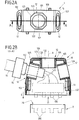
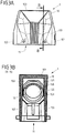
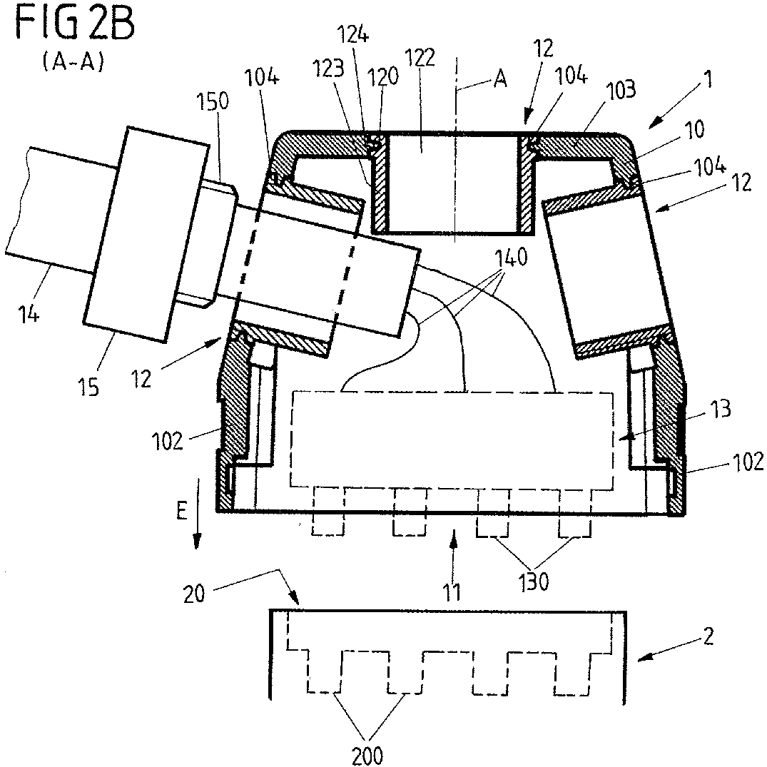
- FIG. 1 to 3A , 3B show an embodiment of a connector 1, which is inserted along an insertion direction E with an associated mating connector 2 (see Figure 2B ) can be connected to establish an electrical connection between the connector 1 and the mating connector 2.
- the connector 1 has a housing 10, which is formed by mutually opposite side walls 101, the end walls 102 connecting the side walls 101 and an upper wall 103 and encloses a receiving space in which a contact insert 13 (see the sectional view according to FIG Figure 2B ) can be included.
- the contact insert 13 has an arrangement of electrical contact elements 130, which form a plug face 11 of the plug connector 1 on an open side of the housing 10 facing away from the upper wall 103 and, when the plug connector 1 is plugged in, with associated mating contact elements 200 of a plug face 20 of the plug connector 2 engage and in this way establish an electrical connection between the connector 1 and the mating connector 2.
- An electrical cable 14 with lead wires 140 guided therein is to be arranged on the plug connector 1.
- the line wires 140 are to be connected to the contact elements 130 of the contact insert 13, so that the cable 14 can be connected to the mating connector 2 via the plug connector 1 and connected to an associated electrical module, for example in a control cabinet.
- Such a connector 1 can be used in very different ways on very different electrical or electronic assemblies to provide very different functions.
- different functionalities can also be provided on the housing 10 of the connector 1, for example in order to connect different electrical cables 14 to the connector 1 or to to enable access and testing on the housing 10 and its housing interior.
- the housing 10 can in principle be manufactured in different ways, for example as a plastic housing by means of plastic injection molding or as an aluminum housing, for example by means of an aluminum die casting process.
- one or more insert elements 12 are selected, wherein a plurality of different insert elements 12 designed to provide different functionalities are present for the manufacture.
- the insert elements selected in this way are connected to the housing 10, the connection being able to take place during manufacture of the housing 10 by means of, for example, plastic injection molding or aluminum die casting, or after the manufacture of the housing 10 by inserting it into insert openings 104 provided on the housing 10.
- the insert elements 12 are integrally connected to the housing 10 during the manufacture of the housing 10, the insert elements 12 are inserted, for example, into an injection molding tool and extrusion-coated with the material of the housing 10 such that the insert elements 12 are integrally received on the housing 10, such as this out Fig. 1 can be seen.
- the insert elements 12 are attached to the housing 10 after the housing 10 has been produced, the insert elements 12 are each inserted into an associated insert opening 104, which was formed on the housing 10 during the production of the housing 10, and in a form-fitting manner or by means of pressing with the Housing 10 connected.
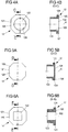
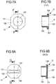
- Figure 4A , 4B to 8A , 8B show different possible configurations of insert elements 12, wherein other variants of insert elements 12 can also be provided, which combine different equipment features with one another.
- the insert elements 12 according to Figure 4A , 4B to 8A , 8B are identical in their outer basic shape and each have a collar section 120 which projects radially to an axial direction A and is circumferentially delimited by an outer contour 121.
- the outer contour 23 has a polygonal shape in a plane perpendicular to the axis direction A, so that by receiving the collar section 120 in an associated insert opening 104 of the housing 10, the respective insert element 12 is fixed in a rotationally fixed manner on the housing 10 and in particular torque loads about the axis direction A on the insert element 12 can be accommodated on the housing 10 without the insert element 12 being able to rotate relative to the housing 10.
- a form-locking device 124 is formed in the form of a groove which is formed radially into the collar section 120 and surrounds the collar section 120 and via which a form-locking connection between the insert element 12 and the housing 10 is produced when the insert element 12 with the housing 10 connected is.
- Each insert element 12 according to 4A, 4B to Figures 8A, 8B also has a shaft section 123 which extends axially along the axial direction A from the collar section 120 and which, when the insert element 12 is connected, extends into the interior of the housing.
- each insert element 12 can be selected in order to be received in each (identically shaped) insert opening 104 on the housing 10 of the connector 1.
- the insert elements 12 are available for selection within the framework of a modular system and have different functionalities.
- the insert element 12 accordingly points in accordance with FIG 4A, 4B an opening 122, which extends along the axial direction A through the insert element 12 and on whose peripheral wall a thread 125 is formed, so that a connecting element 15 (please refer Figure 2B ) can be screwed into the opening 122 by means of a thread on a screw shaft 150 for the screw-fixing of a cable 14.
- the insert element 12 according to 5A, 5B in contrast, forms a stopper which serves to close an insert opening 104 to the outside.
- a cover surface 126 extends across the shaft section 123, so that the shaft section 123 is closed to the outside and the insert element 12 has a continuous, self-contained outer surface.
- a transparent or translucent section can be formed on the top surface 126, which, for example, allows light from an optical signal element to shine through inside the housing.
- an opening 122 which extends through the insert element 12 along the axial direction A and which has a square shape in cross section transverse to the axial direction A.
- an opening 122 is provided which extends through the insert element 12 along the axial direction A and which has a circular shape in cross section. In each case, in the embodiments according to FIG 6A, 6B and 7A, 7B no thread formed.
- a form-fitting section section 127 is formed on a cover surface 126 in the form of a depression with latching elements arranged thereon, which, for example, enables a marking plate to be latched on.
- a shaft section 123 extends from the collar section 120, which points into the housing 10 when the insert element 12 is mounted.
- a shaft section 123 is not mandatory. It is conceivable and possible that such a shaft section 123 is dispensed with in the exemplary embodiments, so that the respective insert element 12 essentially consists of the collar section 120 with the outer contour 121 formed thereon and the form-fitting section 124 formed therein.
- a shaft section can be formed on the collar section 120, which points outwards and thus projects from the housing 10.
- insert elements 12 are selected from the group of insert elements 12 available.
- different functionalities for attaching different cables for example with different cable diameters or for visual inspection or signaling to the housing 10 can be provided on the housing 10.
- insert openings 104 can be formed or provided on different housing walls 102, 103, on which insert elements 12 can be received, so that different insert elements 12 can be attached to different housing walls 102, 103.
- the axial direction A and thus the orientation of the insert elements 12 can thus differ, for example to allow cables to be fed in from different directions.
- the insert elements 12 can be made of plastic or a metal material. It is also conceivable to manufacture the insert elements 12 from a soft material, for example a rubber material or an elastomeric plastic.
- a connector of the type described here can be used in very different ways.
- a connector of the type described here can in particular implement a so-called heavy connector, which is intended to withstand large loads and is designed to be correspondingly resistant.
Landscapes
- Engineering & Computer Science (AREA)
- Manufacturing & Machinery (AREA)
- Connector Housings Or Holding Contact Members (AREA)
Abstract
Bei einem Verfahren zum Herstellen eines Steckverbinders (1) zum steckenden Verbinden mit einem zugeordneten Gegensteckverbinder (2) wird ein Gehäuse (10) hergestellt, in dem ein Kontakteinsatz (13) aufzunehmen ist, der ein Steckgesicht (11) zum steckenden Verbinden mit dem Gegensteckverbinder (2) ausbildet und zumindest ein elektrisches Kontaktelement (130) zum elektrischen Kontaktieren mit zumindest einem Gegenkontaktelement (200) des Gegensteckverbinders (2) aufweist. Bei dem Verfahren ist zudem vorgesehen, dass eine Mehrzahl von zur Verwendung an dem Steckverbinder (1) bestimmten, zum Bereitstellen unterschiedlicher Funktionalitäten an dem Steckverbinder (1) ausgebildeten Einsatzelementen (12) bereitgestellt wird, zumindest ein Einsatzelement (12) aus der Mehrzahl von Einsatzelementen (12) ausgewählt wird und das zumindest eine ausgewählte Einsatzelement (10) bei der Herstellung des Gehäuses (10) mit dem Gehäuse (10) verbunden oder nach der Herstellung des Gehäuses (10) mit dem Gehäuse (10) gefügt wird.
Description
Die Erfindung betrifft ein Verfahren zum Herstellen eines Steckverbinders nach dem Oberbegriff des Anspruches 1, ein Baukastensystem zum Herstellen eines Steckverbinders und einen Steckverbinder.The invention relates to a method for producing a connector according to the preamble of
Im Rahmen eines solchen Verfahrens wird ein Gehäuse hergestellt, in dem ein Kontakteinsatz aufzunehmen ist, der ein Steckgesicht zum steckenden Verbinden mit dem Gegensteckverbinder ausbildet und zumindest ein elektrisches Kontaktelement zum elektrischen Kontaktieren mit zumindest einem Gegenkontaktelement des Gegensteckverbinders aufweist.In the context of such a method, a housing is produced in which a contact insert is to be received, which forms a plug face for the plug-in connection with the mating connector and has at least one electrical contact element for making electrical contact with at least one mating contact element of the mating connector.
Zum Bereitstellen insbesondere schwerer Steckverbinder, die großen Beanspruchungen unterliegen und entsprechend stabil und widerstandsfähig auszugestalten sind, wird ein Gehäuse verwendet, das aus zum Beispiel Kunststoff oder Aluminium gefertigt ist und einen Kontakteinsatz aufnimmt, der eine Anordnung von elektrischen Kontaktelementen in Form von Buchsenkontakten oder Stiftkontakten bereitstellt, um auf diese Weise ein Steckgesicht zum steckenden Verbinden mit einem zugeordneten Gegensteckverbinder auszubilden. Das Gehäuse und der Kontakteinsatz sind hierbei modular ausgebildet und werden miteinander gefügt, um den Steckverbinder bereitzustellen, wobei abhängig von der bestimmungsgemäßen Verwendung des Steckverbinders unterschiedliche Kontakteinsätze mit unterschiedlichen Anordnungen von elektrischen Kontakten und entsprechend auch unterschiedlich geformte Gehäuse mit unterschiedlichen Baugrößen und mechanischen Ausgestaltungen (zum Beispiel zum Bereitstellen einer Verriegelung mit dem Gegensteckverbinder) zum Einsatz kommen.In order to provide heavy connectors in particular, which are subject to high stresses and are designed to be correspondingly stable and resistant, a housing is used which is made of, for example, plastic or aluminum and which receives a contact insert which provides an arrangement of electrical contact elements in the form of socket contacts or pin contacts to form a mating face for mating connection with an associated mating connector in this way. The housing and the contact insert are of modular design and are joined together to provide the connector, depending on the intended use of the connector, different contact inserts with different arrangements of electrical contacts and correspondingly also differently shaped housings with different sizes and mechanical configurations (for example to provide a lock with the mating connector).
Dies hat zur Folge, dass eine beträchtliche Varianz an unterschiedlichen Gehäusen besteht. Diese Varianz wird bei herkömmlichen Steckverbindern noch dadurch vergrößert, dass zum Beispiel ein elektrisches Kabel abhängig von der Verwendung des Steckverbinders in unterschiedlichen Raumrichtungen von dem Steckverbinder zu verlegen ist, was durch das Gehäuse und einen daran vorgesehenen Kabelabgang entsprechend ermöglicht werden muss.As a result, there is a considerable variance in different housings. This variance is further increased in the case of conventional plug connectors in that, for example, an electrical cable, depending on the use of the plug connector, has to be laid by the plug connector in different spatial directions, which must be made possible accordingly by the housing and a cable outlet provided thereon.
Es besteht somit ein Wunsch danach, Möglichkeiten zur Verfügung zu stellen, die Varianz bei Gehäusen für Steckverbinder insbesondere mit Blick auf die Fertigung, die Produktionssteuerung und die Logistik zu reduzieren. Mit Blick auf die Logistik ist beispielsweise erforderlich, sämtliche gegebenenfalls erforderlichen Varianten eines Gehäuses überall dort vorzuhalten, wo solche Varianten gegebenenfalls benötigt werden, was eine große Herausforderung für Lieferketten und das Vorhalten von Varianten bedeutet.There is therefore a desire to provide options for reducing the variance in housings for connectors, particularly with a view to production, production control and logistics. With a view to logistics For example, it is necessary to keep all the variants of a housing that may be required wherever such variants are required, which is a great challenge for supply chains and the provision of variants.
Die
Bei einem aus der
Bei herkömmlichen Steckverbindern kann ein Kabel beispielsweise dadurch an einem Gehäuse festgelegt werden, dass das Kabel mittels einer Kabelverschraubung klemmend zu dem Gehäuse fixiert wird. Eine solche Kabelverschraubung weist üblicherweise ein Verbindungselement auf, das in ein Gewinde des Gehäuses einzuschrauben ist, um auf diese Weise das durch das Verbindungselement hindurchgeführte Kabel zu dem Gehäuse festzulegen. Weil üblicherweise das Gewinde an das Gehäuse angeformt wird, unterschiedliche Gehäuse aber zur Aufnahme unterschiedlicher Kabel, insbesondere Kabel mit unterschiedlichem Leitungsquerschnitt, ausgelegt sein können und somit die Öffnungsgröße genauso wie die Ausgestaltung des Gewindes variieren, ergeben sich herkömmlich eine große Anzahl an unterschiedlichen Gehäusen, für die unterschiedliche Werkzeuge vorzusehen sind.In the case of conventional plug connectors, a cable can be fixed to a housing, for example, in that the cable is fixed to the housing by means of a cable gland. Such a cable gland usually has a connecting element which is to be screwed into a thread of the housing in order in this way to fix the cable which is passed through the connecting element to the housing. Because the thread is usually molded onto the housing, but different housings can be designed to accommodate different cables, especially cables with different cable cross-sections, and thus the opening size as well as the design of the thread vary, conventionally there are a large number of different housings for the different tools have to be provided.
Aufgabe der vorliegenden Erfindung ist es, ein Verfahren und ein Baukastensystem zum Herstellen eines Steckverbinders sowie einen Steckverbinder zur Verfügung zu stellen, mit dem die erforderliche Varianz in den zur Ausbildung eines modularen Steckverbinders bereitzustellenden Gehäusen reduziert sein kann.The object of the present invention is to provide a method and a modular system for producing a plug connector and a plug connector, by means of which the required variance in the housings to be provided for forming a modular plug connector can be reduced.
Diese Aufgabe wird durch einen Gegenstand mit den Merkmalen des Anspruchs 1 gelöst.This object is achieved by an object with the features of
Demnach wird eine Mehrzahl von zur Verwendung an dem Steckverbinder bestimmten, zum Bereitstellen unterschiedlicher Funktionalitäten an dem Steckverbinder ausgebildeten Einsatzelementen bereitgestellt, zumindest ein Einsatzelement aus der Mehrzahl von Einsatzelementen wird ausgewählt, und das zumindest eine ausgewählte Einsatzelement wird bei der Herstellung des Gehäuses mit dem Gehäuse verbunden oder nach der Herstellung des Gehäuses mit dem Gehäuse gefügt.Accordingly, a plurality of insert elements intended for use on the plug connector and designed to provide different functionalities on the plug connector are provided, at least one insert element from the A plurality of insert elements is selected, and the at least one selected insert element is connected to the housing when the housing is manufactured or is joined to the housing after the housing is manufactured.
Im Rahmen der vorliegenden Erfindung wird eine Mehrzahl von unterschiedlichen Einsatzelementen bereitgestellt, die dazu dienen, unterschiedliche Funktionalitäten an einem Steckverbindergehäuse bereitzustellen. Aus diesen Einsatzelementen können ein Einsatzelement oder mehrere Einsatzelemente ausgewählt werden, um die so ausgewählten Einsatzelemente an einem jeweiligen Gehäuse zu verwenden.Within the scope of the present invention, a plurality of different insert elements are provided, which serve to provide different functionalities on a connector housing. One insert element or several insert elements can be selected from these insert elements in order to use the insert elements selected in this way on a respective housing.
Auf diese Weise wird möglich, die Variantenvielfalt bei Gehäusen zu reduzieren und das Verfahren zur Herstellung des Gehäuses zu vereinfachen. So wird eine Varianz an Gehäusen über die Einsatzelemente zur Verfügung gestellt, wobei Gehäuse gleicher äußerer Bauform durch Auswahl von Einsatzelementen mit unterschiedlichen Funktionalitäten zur Verfügung gestellt werden können. Die Bereitstellung einer Varianz an Gehäusen wird somit auf die Bereitstellung und Auswahl von Einsatzelementen verlagert.In this way it is possible to reduce the variety of variants in housings and to simplify the method for producing the housing. A variety of housings is thus made available via the insert elements, and housings of the same outer design can be made available by selecting insert elements with different functionalities. The provision of a variety of housings is thus shifted to the provision and selection of insert elements.
Das zumindest eine ausgewählte Einsatzelement ist, nach Vollendung der Herstellung, fest und dauerhaft mit dem Gehäuse verbunden. Die Verbindung des ausgewählten Einsatzelements mit dem Gehäuse kann hierbei bei der Herstellung des Gehäuses oder nach der Herstellung des Gehäuses erfolgen.The at least one selected insert element is, after completion of the manufacture, firmly and permanently connected to the housing. The connection of the selected insert element to the housing can take place during the production of the housing or after the production of the housing.
So kann das Gehäuse beispielsweise aus Kunststoff mittels Spritzgießen hergestellt werden. Das zumindest eine ausgewählte Einsatzelement kann in diesem Fall bei der Herstellung des Gehäuses von dem Material des Gehäuses zumindest abschnittsweise umspritzt werden, sodass das zumindest eine Einsatzelement stoffschlüssig mit dem Gehäuse verbunden wird. Das zumindest eine ausgewählte Einsatzelement und das Gehäuse gehen somit eine integrale, stoffschlüssige Verbindung miteinander ein, wobei sich die Materialien des Gehäuses und des Einsatzelements unterscheiden können. Beispielsweise kann das Gehäuse aus Kunststoff und das Einsatzelement aus einem Metallwerkstoff gefertigt sein, oder das Gehäuse und das Einsatzelement können aus unterschiedlichen Kunststoffen ausgebildet sein.For example, the housing can be made of plastic by means of injection molding. In this case, the at least one selected insert element can be extrusion-coated at least in sections from the material of the housing during the manufacture of the housing, so that the at least one insert element is integrally connected to the housing. The at least one selected insert element and the housing thus form an integral, integral connection with one another, the materials of the housing and the insert element being able to differ. For example, the housing can be made of plastic and the insert element made of a metal material, or the housing and insert element can be made of different plastics.
Wird das Gehäuse aus einem Metallwerkstoff, zum Beispiel Aluminium gefertigt, kann das Gehäuse auch mittels zum Beispiel einem Druckgussverfahren, zum Beispiel Aluminiumdruckguss, gefertigt werden. Auch in diesem Fall ist denkbar, das zumindest eine ausgewählte Einsatzelement bei der Herstellung des Gehäuses mit dem Material des Gehäuses zumindest abschnittsweise zu umgießen, sodass eine integrale, stoffschlüssige Verbindung zwischen dem zumindest einen ausgewählten Einsatzelement und dem Gehäuse geschaffen wird.If the housing is manufactured from a metal material, for example aluminum, the housing can also be manufactured by means of, for example, a die casting process, for example aluminum die casting. In this case too, it is conceivable, at least Pour at least sections of a selected insert element during the manufacture of the housing with the material of the housing, so that an integral, integral connection is created between the at least one selected insert element and the housing.
In alternativer Ausgestaltung des Verfahrens ist auch möglich, ein oder mehrere ausgewählte Einsatzelemente nach der Herstellung des Gehäuses mit dem Gehäuse zu fügen. In diesem Fall kann das zumindest eine ausgewählte Einsatzelement nach der Herstellung des Gehäuses zum Beispiel formschlüssig mit dem Gehäuse verbunden oder mit dem Gehäuse verpresst werden. Bei dieser Ausgestaltung wird somit zunächst das Gehäuse als gesondertes Bauteil hergestellt, beispielsweise mittels Kunststoffspritzgießen oder mittels eines Aluminiumdruckgussverfahrens, sodass das Gehäuse zunächst als gesondertes Bauteil vorliegt. Sodann werden ein oder mehrere Einsatzelemente aus den zur Verfügung stehenden Einsatzelementen ausgewählt und mit dem Gehäuse gefügt, indem die ausgewählten Einsatzelemente zum Beispiel an dafür vorgesehene Einsatzöffnungen an dem Gehäuse angesetzt werden.In an alternative embodiment of the method, it is also possible to join one or more selected insert elements to the housing after the production of the housing. In this case, the at least one selected insert element can, for example, be positively connected to the housing or pressed to the housing after the production of the housing. In this embodiment, the housing is thus first produced as a separate component, for example by means of plastic injection molding or by means of an aluminum die casting process, so that the housing is initially present as a separate component. Then one or more insert elements are selected from the available insert elements and joined to the housing, for example by attaching the selected insert elements to the openings provided on the housing for this purpose.
Das zumindest eine ausgewählte Einsatzelement ist nach Vollendung der Herstellung vorzugsweise fest und dauerhaft mit dem Gehäuse verbunden. Das zumindest eine ausgewählte Einsatzelement wird somit zum Bestandteil des Gehäuses und stellt eine jeweils durch das Einsatzelement geschaffene Funktionalität an dem Gehäuse zur Verfügung.The at least one selected insert element is preferably firmly and permanently connected to the housing after completion of the production. The at least one selected insert element thus becomes part of the housing and provides a functionality on the housing created by the insert element.
Insbesondere soll das zumindest eine ausgewählte Einsatzelement so fest mit dem Gehäuse verbunden werden, dass das Einsatzelement belastbar, drehfest und axial nicht ohne weiteres lösbar zu dem Gehäuse festgelegt ist.In particular, the at least one selected insert element should be connected to the housing so firmly that the insert element is fixed to the housing in a load-bearing, rotationally fixed and axially non-detachable manner.
In einer Ausgestaltung weisen die unterschiedlichen Einsatzelemente jeweils eine in ihren äußeren Abmessungen und der äußeren Formgebung gleiche Bauform auf. Insbesondere kann jedes Einsatzelement einen Bundabschnitt aufweisen, der eine umfänglich um eine Achsrichtung erstreckt Außenkontur ausbildet, über die das Einsatzelement mit dem Gehäuse verbunden wird. In der Formgebung der Außenkontur sind die Einsatzelemente vorzugsweise gleich ausgebildet und weisen gleiche Abmessungen auf, sodass jedes der Einsatzelemente an einer gleichartigen, komplementären Einsatzöffnung des Gehäuses verwendet werden kann, an der Einsatzöffnung somit jedes der Einsatzelemente befestigt werden kann.In one embodiment, the different insert elements each have the same shape in terms of their outer dimensions and their outer shape. In particular, each insert element can have a collar section which forms an outer contour which extends circumferentially about an axial direction and via which the insert element is connected to the housing. In the shape of the outer contour, the insert elements are preferably of the same design and have the same dimensions, so that each of the insert elements can be used on a similar, complementary insert opening of the housing, so that each of the insert elements can be attached to the insert opening.
Die Außenkontur dient hierbei vorzugsweise auch zur drehfesten Festlegung des Einsatzelements an dem Gehäuse. Hierzu kann die Außenkontur beispielsweise, betrachtet umfänglich um die Achsrichtung, eine Form aufweisen, die von einer rotationssymmetrischen Form abweicht, beispielsweise eine Mehrkantform, über die der Bundabschnitt um die Achsrichtung drehfest mit dem Gehäuse verbunden wird. Durch Einfassen der Außenkontur an dem Gehäuse wird das Einsatzelement somit derart an dem Gehäuse festgelegt, dass bei einer Drehmomentbelastung, zum Beispiel bei Einschrauben eines Verbindungselements oder dergleichen, das Einsatzelement sich nicht relativ zu dem Gehäuse verdrehen kann.The outer contour is preferably also used for the rotationally fixed fixing of the insert element on the housing. For this purpose, the outer contour, for example, viewed circumferentially around the axial direction, can have a shape that deviates from a rotationally symmetrical shape, for example a polygonal shape, via which the collar section is connected to the housing in a rotationally fixed manner about the axial direction. By inserting the outer contour on the housing, the insert element is thus fixed on the housing in such a way that when a torque is applied, for example when a connecting element or the like is screwed in, the insert element cannot rotate relative to the housing.
In einer Ausgestaltung weist der Bundabschnitt im Bereich der Außenkontur eine Formschlusseinrichtung auf, zum Beispiel in Form einer an dem Bundabschnitt umlaufend geformten Nut oder in Form eines umlaufenden, radial vorspringenden Stegs, über die der Bundabschnitt entlang der Achsrichtung formschlüssig mit dem Gehäuse verbunden werden kann. Wird das Einsatzelement bei Herstellung des Gehäuses von dem Material des Gehäuses umspritzt oder umgossen, so wird auf diese Weise zusätzlich zu einem Stoffschluss ein Formschluss zwischen dem Einsatzelement und dem Gehäuse hergestellt. Wird das Einsatzelement nach Herstellung des Gehäuses in eine Einsatzöffnung gefügt, so wird dabei ein Formschluss durch Eingriff einer komplementären Eingriffseinrichtung des Gehäuses in die Formschlusseinrichtung am Bundabschnitt des Einsatzelements hergestellt.In one configuration, the collar section has a form-fitting device in the region of the outer contour, for example in the form of a groove formed circumferentially on the collar section or in the form of a circumferential, radially projecting web, via which the collar section can be positively connected to the housing along the axial direction. If the material of the housing is encapsulated or cast around the insert element during manufacture of the housing, a positive connection between the insert element and the housing is produced in this way in addition to a material connection. If the insert element is inserted into an insert opening after the housing has been produced, then a positive connection is produced by engagement of a complementary engagement device of the housing in the form-locking device on the collar section of the insert element.
In einer Ausgestaltung weist jedes der unterschiedlichen Einsatzelemente einen Schaftabschnitt auf, der axial entlang der Achsrichtung von dem Bundabschnitt erstreckt ist. Der Schaftabschnitt steht somit axial von dem Bundabschnitt vor und kann sich, nach Verbinden des Einsatzelements mit dem Gehäuse, zum Beispiel in einen Innenraum des Gehäuses hinein erstrecken.In one configuration, each of the different insert elements has a shaft section which extends axially along the axial direction from the collar section. The shaft section thus protrudes axially from the collar section and, after connecting the insert element to the housing, can extend, for example, into an interior of the housing.
Ein solcher Schaftabschnitt ist jedoch nicht zwingend vorzusehen. Das Einsatzelement kann auch im Wesentlichen aus dem Bundabschnitt bestehen.However, such a shaft section is not mandatory. The insert element can also consist essentially of the collar section.
Die unterschiedlichen Einsatzelemente der Mehrzahl von Einsatzelementen dienen dazu, unterschiedliche Funktionalitäten an dem Gehäuse bereitzustellen.The different insert elements of the plurality of insert elements serve to provide different functionalities on the housing.
So kann ein Einsatzelement der Mehrzahl von Einsatzelementen beispielsweise eine Öffnung (oder auch mehrere Öffnungen) zum Einführen eines elektrischen Kabels (oder auch mehrerer elektrischer Kabel) in das Gehäuse ausbilden. Eine solche Öffnung kann einen kreisförmigen Querschnitt oder auch einen kantigen, zum Beispiel viereckigen Querschnitt aufweisen.For example, one insert element of the plurality of insert elements can form an opening (or also a plurality of openings) for introducing an electrical cable (or also a plurality of electrical cables) into the housing. Such an opening can have a circular cross section or an angular, for example square, cross section.
Ein Einsatzelement kann hierbei eine Öffnung aufweisen, die kein Gewinde trägt und somit von einer glatten Wandung umgeben ist.An insert element can have an opening that has no thread and is therefore surrounded by a smooth wall.
Ein anderes Einsatzelement kann demgegenüber ein im Bereich der Öffnung geformtes Gewinde aufweisen, sodass zum Beispiel ein Verbindungselement zum schraubenden Festlegen eines elektrischen Kabels an dem Gehäuse in die Öffnung des Einsatzelements eingeschraubt werden kann.Another insert element, in contrast, can have a thread formed in the area of the opening, so that, for example, a connecting element for screwing an electrical cable to the housing can be screwed into the opening of the insert element.
Ein anderes Einsatzelement kann beispielsweise als Stopfen ausgebildet sein und dazu dienen, eine an dem Gehäuse vorgesehene Einsatzöffnung nach außen hin zu verschließen. Ein solches Einsatzelement kann beispielsweise eine quer zur Achsrichtung erstreckte Deckfläche ausbilden, die zum Verschließen des Gehäuses nach außen hin dient.Another insert element can, for example, be designed as a stopper and serve to close an insert opening provided on the housing to the outside. Such an insert element can, for example, form a cover surface which extends transversely to the axial direction and serves to close the housing to the outside.
Ein wiederum anderes Einsatzelement kann beispielsweise einen zumindest abschnittweise transparenten oder transluzenten Abschnitt aufweisen, sodass über das Einsatzelement beispielsweise eine visuelle Inspektion des Gehäuseinneren oder ein Durchscheinen des Gehäuses, zum Beispiel bei Anordnung von optischen Signalelementen im Inneren des Gehäuses, erfolgen kann.Yet another insert element can have, for example, an at least partially transparent or translucent section, so that the insert element can be used, for example, to visually inspect the interior of the housing or to show through the housing, for example when optical signal elements are arranged in the interior of the housing.
Die einzelnen Ausstattungsmerkmale sind gegebenenfalls auch in Kombination an einem Einsatzelement verwendbar. So kann ein Einsatzelement beispielsweise eine gegebenenfalls mit einem Gewinde ausgestattete Öffnung zum Durchführen eines Kabels und zudem einen transparenten oder transluzenten Abschnitt aufweisen.The individual equipment features can optionally also be used in combination on an insert element. For example, an insert element may have an opening, optionally equipped with a thread, for the passage of a cable and also a transparent or translucent section.
In einer Ausgestaltung kann an dem Gehäuse zumindest eine Einsatzöffnung zum Aufnehmen des zumindest einen ausgewählten Einsatzelements geformt werden. Das Formen einer solchen Einsatzöffnung kann bei Verbindung mit dem ausgewählten Einsatzelement erfolgen (zum Beispiel bei Herstellung des Gehäuses mittels Spritzgießen), sodass bei der Herstellung des Gehäuses das Einsatzelement in einer zugeordneten Einsatzöffnung des Gehäuses integral angeordnet wird. Das Formen einer solchen Einsatzöffnung kann aber auch vor Verbindung mit dem ausgewählten Einsatzelement erfolgen, sodass das ausgewählte Einsatzelement zur Verbindung in eine zugeordnete Einsatzöffnung des Gehäuses eingesetzt werden kann.In one embodiment, at least one insert opening for receiving the at least one selected insert element can be formed on the housing. Such an insert opening can be formed when it is connected to the selected insert element (for example when the housing is manufactured by means of injection molding), so that when the housing is manufactured the insert element is integrally arranged in an associated insert opening of the housing. Such an insert opening can also be formed before connection to the selected insert element, so that the selected insert element can be inserted into an associated insert opening of the housing for connection.
Das Gehäuse kann zum Beispiel eine näherungsweise quaderförmige Grundform aufweisen. Insbesondere kann das Gehäuse durch einander gegenüberliegende Seitenwandungen gebildet sein, die über stirnseitige Wandungen und eine obere Gehäusewandung miteinander verbunden sind. Das Gehäuse kann auf diese Weise einen Aufnahmeraum einfassen, in dem der Kontakteinsatz aufzunehmen ist, wobei das Gehäuse zum Beispiel an der Seite offen ist, an der der Kontakteinsatz das Steckgesicht ausbildet.For example, the housing can have an approximately cuboid basic shape. In particular, the housing can be formed by mutually opposite side walls which are connected to one another via end walls and an upper housing wall. In this way, the housing can enclose a receiving space in which the contact insert is to be received, the housing being open, for example, on the side on which the contact insert forms the mating face.
An dem Gehäuse können hierbei an unterschiedlichen Wandungen, beispielsweise an den Seitenwandungen, den stirnseitigen Wandungen oder auch an der oberen Gehäusewandung, mehrere (in ihrer Formgebung gleich ausgebildete) Einsatzöffnungen vorgesehen werden, sodass mehrere Einsatzelemente mit dem Gehäuse verbunden werden können.In this case, several insert openings (with the same design) can be provided on the housing on different walls, for example on the side walls, the end walls or also on the upper housing wall, so that several insert elements can be connected to the housing.
Die Aufgabe wird auch gelöst durch ein Baukastensystem zum Herstellen eines Steckverbinders unter Verwendung des Verfahrens der vorangehend beschriebenen Art. Ein solches Baukastensystem weist eine Mehrzahl von zur Verwendung an dem Steckverbinder bestimmten, zum Bereitstellen unterschiedlicher Funktionalitäten an dem Steckverbinder ausgebildeten Einsatzelementen auf, die wahlweise an dem Gehäuse verwendbar sind.The object is also achieved by a modular system for producing a plug connector using the method of the type described above. Such a modular system has a plurality of insert elements designed for use on the plug connector and designed to provide different functionalities on the plug connector, optionally on the Housing can be used.
Solche Einsatzelemente können eine gleiche äußere Grundform, mit einem Bundabschnitt und einer daran geformten, gleich ausgebildeten Außenkontur, aufweisen, sodass die Einsatzelemente in gleichen Einsatzöffnungen an dem Gehäuse aufgenommen werden können. Ein Gehäuse kann somit variabel mit einem gerade ausgewählten, eine bestimmte Funktionalität bereitstellenden Einsatzelement verbunden werden.Such insert elements can have the same outer basic shape, with a collar section and an identically formed outer contour formed thereon, so that the insert elements can be received in the same insert openings on the housing. A housing can thus be variably connected to an insert element that has just been selected and provides a certain functionality.
Die Aufgabe wird auch gelöst durch einen Steckverbinder zum steckenden Verbinden mit einem zugeordneten Gegensteckverbinder. Ein solcher Steckverbinder umfasst ein Gehäuse und einen in dem Gehäuse aufzunehmenden Kontakteinsatz, der ein Steckgesicht zum steckenden Verbinden mit dem Gegensteckverbinder ausbilden und somit ein elektrisches Kontaktelement zum elektrischen Kontaktieren mit zumindest einem Gegenkontaktelement des Gegensteckverbinders aufweist. Das Gehäuse ist mit zumindest einem ausgewählten Einsatzelement aus einer Mehrzahl von zur Verwendung an dem Steckverbinder bestimmten, zum Bereitstellen unterschiedlicher Funktionalitäten an dem Steckverbinder ausgebildeten Einsatzelementen drehfest und dauerhaft verbunden.The object is also achieved by a plug connector for plugging connection with an associated mating connector. Such a connector comprises a housing and a contact insert to be accommodated in the housing, which form a plug face for plugging connection with the mating connector and thus has an electrical contact element for making electrical contact with at least one mating contact element of the mating connector. The housing is provided with at least one selected insert element from a plurality of functionalities intended for use on the plug connector and for providing different functionalities insert elements formed on the connector are non-rotatably and permanently connected.
Zu den Vorteilen und vorteilhaften Ausgestaltungen eines solchen Steckverbinders soll auch auf das vorangehend zum Verfahren Ausgeführte verwiesen werden.Regarding the advantages and advantageous configurations of such a connector, reference should also be made to what has been said above about the method.
Der der Erfindung zugrunde liegende Gedanke soll nachfolgend anhand der in den Figuren dargestellten Ausführungsbeispielen näher erläutert werden. Es zeigen:
- Fig. 1
- eine Ansicht eines Ausführungsbeispiels eines Steckverbinderteils mit einem Gehäuse und daran angeordneten Einsatzelementen;
- Fig. 2A
- eine Draufsicht auf den Steckverbinder;
- Fig. 2B
- eine Schnittansicht entlang der Linie A-A gemäß
Fig. 2A . - Fig. 3A
- eine Seitensicht des Steckverbinders;
- Fig. 3B
- eine Schnittansicht entlang der Linie B-B gemäß
Fig. 3A . - Fig. 4A
- eine Ansicht einer Ausgestaltung eines Einsatzelements;
- Fig. 4B
- eine Schnittansicht entlang der Linie C-C gemäß
Fig. 4A ; - Fig. 5A
- eine Ansicht einer anderen Ausgestaltung eines Einsatzelements;
- Fig. 5B
- eine Schnittansicht entlang der Linie D-D gemäß
Fig. 5A ; - Fig. 6A
- eine Ansicht einer wiederum anderer Ausgestaltung eines Einsatzelements;
- Fig. 6B
- eine Schnittansicht in der Linie E-E gemäß
Fig. 6A ; - Fig. 7A
- eine Ansicht einer wiederum anderen Ausgestaltung eines Einsatzelements;
- Fig. 7B
- eine Schnittansicht entlang der Linie F-F gemäß
Fig. 7A ; - Fig. 8A
- eine Ansicht einer wiederum anderen Ausgestaltung eines Einsatzelements; und
- Fig. 8B
- eine Schnittansicht entlang der Linie G-G gemäß
Fig. 8A .
- Fig. 1
- a view of an embodiment of a connector part with a housing and insert elements arranged thereon;
- Figure 2A
- a plan view of the connector;
- Figure 2B
- a sectional view taken along the line AA
Figure 2A . - Figure 3A
- a side view of the connector;
- Figure 3B
- a sectional view taken along the line BB
Figure 3A . - Figure 4A
- a view of an embodiment of an insert element;
- Figure 4B
- a sectional view taken along line CC according
Figure 4A ; - Figure 5A
- a view of another embodiment of an insert element;
- Figure 5B
- a sectional view along the line DD according
Figure 5A ; - Figure 6A
- a view of yet another embodiment of an insert element;
- Figure 6B
- a sectional view in the line EE according
Figure 6A ; - Figure 7A
- a view of yet another embodiment of an insert element;
- Figure 7B
- a sectional view taken along the line FF
Figure 7A ; - Figure 8A
- a view of yet another embodiment of an insert element; and
- Figure 8B
- a sectional view taken along the line GG
Figure 8A .
Der Steckverbinder 1 weist ein Gehäuse 10 auf, das durch einander gegenüberliegende Seitenwandungen 101, die Seitenwandungen 101 miteinander verbindende stirnseitige Wandungen 102 und eine obere Wandung 103 gebildet ist und einen Aufnahmeraum einfasst, in dem ein Kontakteinsatz 13 (siehe die Schnittansicht gemäß
An dem Steckverbinder 1 ist ein elektrisches Kabel 14 mit darin geführten Leitungsadern 140 anzuordnen. Die Leitungsadern 140 sind mit den Kontaktelementen 130 des Kontakteinsatzes 13 zu verbinden, sodass über den Steckverbinder 1 das Kabel 14 mit dem Gegensteckverbinder 2 verbunden und darüber an eine zugeordnete elektrische Baugruppe, zum Beispiel in einem Schaltschrank, angeschlossen werden kann.An
Ein solcher Steckverbinder 1 kann in ganz unterschiedlicher Weise an ganz unterschiedlichen elektrischen oder elektronischen Baugruppen zum Bereitstellen von ganz unterschiedlichen Funktionen zum Einsatz kommen. Abhängig von der Verwendung des Steckverbinders 1 können hierbei auch an dem Gehäuse 10 des Steckverbinders 1 unterschiedliche Funktionalitäten zur Verfügung zu stellen sein, um zum Beispiel unterschiedliche elektrische Kabel 14 mit dem Steckverbinder 1 zu verbinden oder um einen Zugriff und eine Prüfung am Gehäuse 10 und dessen Gehäuseinnerem zu ermöglichen.Such a
Um die Variantenvielfalt insbesondere mit Blick auf die Herstellung und einer damit einhergehenden Bereitstellung von Werkzeugen zu reduzieren, wird vorliegend vorgeschlagen, an dem Gehäuse 10 ein oder mehrere Einsatzelemente 12 zu verwenden, die nach Fertigstellung des Steckverbinders 1 fest mit dem Gehäuse 10 verbunden sind und somit eine Einheit mit dem Gehäuse 10 bilden, für die Herstellung des Gehäuses 10 aber in variabler Weise ausgewählt und an dem Gehäuse 10 angeordnet werden können.In order to reduce the variety of variants, particularly with a view to the production and the associated provision of tools, it is proposed in the present case to use one or
Das Gehäuse 10 kann grundsätzlich auf unterschiedliche Weise gefertigt werden, zum Beispiel als Kunststoffgehäuse mittels Kunststoffspritzgießen oder als Aluminiumgehäuse zum Beispiel mittels eines Aluminiumdruckgussverfahrens.The
Zum Herstellen des Gehäuses 10 werden ein oder mehrere jeweils vorgesehene Einsatzelemente 12 ausgewählt, wobei für die Herstellung eine Mehrzahl von unterschiedlichen, zur Bereitstellung unterschiedlicher Funktionalitäten ausgebildeten Einsatzelementen 12 vorliegt. Die so ausgewählten Einsatzelemente werden mit dem Gehäuse 10 verbunden, wobei die Verbindung bei Herstellung des Gehäuses 10 mittels zum Beispiel Kunststoffspritzgießen oder Aluminiumdruckgießen oder auch nach der Herstellung des Gehäuses 10 durch Einsetzen in am Gehäuse 10 vorgesehene Einsatzöffnungen 104 erfolgen kann.To produce the
Werden die Einsatzelemente 12 bei der Herstellung des Gehäuses 10 integral mit dem Gehäuse 10 verbunden, so werden die Einsatzelemente 12 zum Beispiel in ein Spritzgusswerkzeug eingelegt und mit dem Material des Gehäuses 10 umspritzt derart, dass die Einsatzelemente 12 integral am Gehäuse 10 aufgenommen werden, wie dies aus
Werden hingegen die Einsatzelemente 12 nach Herstellung des Gehäuses 10 an das Gehäuse 10 angesetzt, so werden die Einsatzelemente 12 jeweils in eine zugeordnete Einsatzöffnung 104, die bei der Herstellung des Gehäuses 10 am Gehäuse 10 geformt worden ist, eingesetzt und formschlüssig oder mittels Verpressen mit dem Gehäuse 10 verbunden.If, on the other hand, the
Die Einsatzelemente 12 gemäß
Die Außenkontur 23 weist in einer Ebene senkrecht zur Achsrichtung A eine Mehrkantform auf, sodass durch Aufnehmen des Bundabschnitts 120 in einer zugeordneten Einsatzöffnung 104 des Gehäuses 10 das jeweilige Einsatzelement 12 drehfest an dem Gehäuse 10 festgelegt wird und insbesondere Drehmomentbelastungen um die Achsrichtung A auf das Einsatzelement 12 am Gehäuse 10 aufgenommen werden können, ohne dass sich das Einsatzelement 12 zu dem Gehäuse 10 verdrehen kann.The outer contour 23 has a polygonal shape in a plane perpendicular to the axis direction A, so that by receiving the
Im Bereich der Außenkontur 121 ist eine Formschlusseinrichtung 124 in Form einer radial in den Bundabschnitt 120 eingeformten, um den Bundabschnitt 120 umlaufenden Nut geformt, über die ein Formschluss zwischen dem Einsatzelement 12 und dem Gehäuse 10 hergestellt wird, wenn das Einsatzelement 12 mit dem Gehäuse 10 verbunden ist.In the area of the
Ein jedes Einsatzelement 12 gemäß
Weil sich die Einsatzelemente 12 in ihrer äußeren Grundform gleichen, kann ein jedes Einsatzelement 12 ausgewählt werden, um in einer jeden (gleich geformten) Einsatzöffnung 104 am Gehäuse 10 des Steckverbinders 1 aufgenommen zu werden.Because the
Die Einsatzelemente 12 liegen im Rahmen eines Baukastensystems zur Auswahl vor und weisen unterschiedliche Funktionalitäten auf.The
So weist das Einsatzelement 12 gemäß
Das Einsatzelement 12 gemäß
Bei der Ausgestaltung des Einsatzelements 12 gemäß
Bei der Ausgestaltung des Einsatzelements 12 gemäß
Bei der Ausgestaltung des Einsatzelements 12 gemäß
Bei den Ausführungsbeispielen gemäß
Alternativ kann ein Schaftabschnitt an dem Bundabschnitt 120 geformt sein, der nach außen weist und somit von dem Gehäuse 10 vorsteht.Alternatively, a shaft section can be formed on the
Zur Fertigung des Gehäuses 10 werden ein oder mehrere Einsatzelemente 12 aus der Gruppe der zur Verfügung stehenden Einsatzelemente 12 ausgewählt. Auf diese Weise können am Gehäuse 10 unterschiedliche Funktionalitäten zum Anbringen unterschiedlicher Kabel zum Beispiel mit unterschiedlichem Kabeldurchmesser oder für eine visuelle Inspektion oder eine Signalisierung an dem Gehäuse 10 zur Verfügung gestellt werden. Wie aus
Die Einsatzelemente 12 können aus Kunststoff oder einem Metallmaterial gefertigt sein. Denkbar ist zudem auch, die Einsatzelemente 12 aus einem Weichmaterial, zum Beispiel einem Gummimaterial oder einem elastomeren Kunststoff zu fertigen.The
Der der Erfindung zugrunde liegende Gedanke ist nicht auf die vorangehend geschilderten Ausführungsbeispiele beschränkt, sondern lässt sich auch in gänzlich andersgearteter Weise verwirklichen.The idea on which the invention is based is not limited to the exemplary embodiments described above, but can also be implemented in a completely different manner.
Ein Steckverbinder der hier beschriebenen Art kann in ganz unterschiedlicher Weise verwendet werden. Ein Steckverbinder der hier beschriebenen Art kann insbesondere einen sogenannten schweren Steckverbinder verwirklichen, der großen Belastungen widerstehen soll und entsprechend widerstandsfähig ausgebildet ist.A connector of the type described here can be used in very different ways. A connector of the type described here can in particular implement a so-called heavy connector, which is intended to withstand large loads and is designed to be correspondingly resistant.
- 11
- SteckverbinderConnectors
- 1010th
- Gehäusecasing
- 101101
- SeitenwandungenSide walls
- 102102
- Stirnseitige WandungenFace walls
- 103103
- Obere GehäusewandungUpper housing wall
- 104104
- EinsatzöffnungenInsert openings
- 1111
- SteckgesichtMating face
- 1212th
- EinsatzelementInsert element
- 120120
- BundabschnittFret section
- 121121
- AußenkonturOuter contour
- 122122
- Öffnungopening
- 123123
- SchaftabschnittShaft section
- 124124
- FormschlusseinrichtungPositive locking device
- 125125
- Gewindethread
- 126126
- DeckflächeTop surface
- 127127
- FormschlussabschnittForm fit section
- 1313
- KontakteinsatzContact insert
- 130130
- Elektrische KontaktelementeElectrical contact elements
- 1414
- Kabelelectric wire
- 140140
- LeitungsaderWire
- 1515
- VerbindungselementFastener
- 150150
- SchraubschaftScrew shaft
- 22nd
- GegensteckverbinderMating connector
- 2020
- SteckgesichtMating face
- 200200
- GegenkontaktelementMating contact element
- AA
- AchsrichtungAxis direction
- EE
- SteckrichtungDirection of insertion
Claims (12)
Applications Claiming Priority (1)
| Application Number | Priority Date | Filing Date | Title |
|---|---|---|---|
| DE102019100583.3A DE102019100583C5 (en) | 2019-01-11 | 2019-01-11 | Method and modular system for producing a connector by selecting an insert element |
Publications (2)
| Publication Number | Publication Date |
|---|---|
| EP3680997A1 true EP3680997A1 (en) | 2020-07-15 |
| EP3680997B1 EP3680997B1 (en) | 2023-11-29 |
Family
ID=69147516
Family Applications (1)
| Application Number | Title | Priority Date | Filing Date |
|---|---|---|---|
| EP20150658.1A Active EP3680997B1 (en) | 2019-01-11 | 2020-01-08 | Method for producing a connector by selecting an insert element |
Country Status (3)
| Country | Link |
|---|---|
| EP (1) | EP3680997B1 (en) |
| CN (2) | CN111435779A (en) |
| DE (1) | DE102019100583C5 (en) |
Citations (10)
| Publication number | Priority date | Publication date | Assignee | Title |
|---|---|---|---|---|
| US5062807A (en) | 1990-10-22 | 1991-11-05 | Woodhead Industries, Inc. | Lighted electrical connector permitting multi directional viewing |
| DE10303800B3 (en) | 2003-01-31 | 2004-06-03 | Harting Electric Gmbh & Co. Kg | Fixing and contacting device for contact insert in plug connector housing, uses spaced formations at inside corners of connector housing shells and electrically-conducting spring element |
| DE20308570U1 (en) * | 2003-06-02 | 2004-10-07 | Wieland Electric Gmbh | Variable cable gland |
| DE102005042027A1 (en) | 2005-09-02 | 2007-03-15 | Segu Systemelektrik Gmbh | Electrical connector and method of making the same |
| WO2014074245A1 (en) * | 2012-11-08 | 2014-05-15 | Delphi Technologies, Inc. | Connector backshell having multiple cable exit configurations |
| DE102013109653A1 (en) | 2013-09-04 | 2015-03-05 | Harting Electric Gmbh & Co. Kg | connector housing |
| EP2486637B1 (en) | 2009-10-09 | 2015-04-15 | Harting Electric GmbH & Co. KG | Cable lead-through in plug-in connector housings |
| WO2016041546A1 (en) | 2014-09-18 | 2016-03-24 | Harting Electric Gmbh & Co. Kg | Plug connector housing with a seal |
| DE102014222908A1 (en) | 2014-11-10 | 2016-05-12 | Böllhoff Verbindungstechnik GmbH | Casting mold, insert for a casting mold, a casting and casting method therefor |
| DE102016108314A1 (en) | 2016-05-04 | 2017-11-09 | Amphenol-Tuchel Electronics Gmbh | Umspritz adapter |
Family Cites Families (14)
| Publication number | Priority date | Publication date | Assignee | Title |
|---|---|---|---|---|
| DE1901731U (en) * | 1964-05-06 | 1964-10-08 | Bingel & Co K | ELECTRIC CONNECTOR. |
| DE3712258A1 (en) | 1987-04-10 | 1988-11-10 | Thyssen Industrie | SOCKET FOR SINGLE AND MULTIPOLE COUPLING DEVICES OF ROUND CONNECTORS WITH THE SAME CONTACT IMAGE |
| US5108313A (en) * | 1989-10-05 | 1992-04-28 | E. I. Du Pont De Nemours And Company | Modular connector |
| DE29801984U1 (en) * | 1998-02-06 | 1998-03-26 | Schmitt, Fred R., 74388 Talheim | Connector housing in 19 inch device system |
| EP1357643B1 (en) * | 2002-04-22 | 2010-07-21 | Fred R. Schmitt | Bus-Housing and insert parts for the cable openings of the Bus-housing |
| DE10239421B4 (en) | 2002-08-28 | 2006-06-01 | Aloys Wobben | plug |
| DE102006052894B4 (en) * | 2006-11-08 | 2013-05-16 | Phoenix Contact Gmbh & Co. Kg | Terminal block, test plug and test terminal block |
| DE202009015571U1 (en) * | 2009-11-14 | 2011-03-24 | Wieland Electric Gmbh | Electrical connector |
| DE102012107270A1 (en) * | 2012-08-08 | 2014-02-13 | Harting Electric Gmbh & Co. Kg | Connector housing with an RFID transponder |
| US9118138B2 (en) * | 2013-04-16 | 2015-08-25 | Tyco Electronics Services Gmbh | Electrical connector having resilient latches |
| DE102015104029B3 (en) * | 2015-03-18 | 2016-09-22 | Harting Electric Gmbh & Co. Kg | Hybrid connector housing |
| DE102015121156B4 (en) * | 2015-12-04 | 2019-01-31 | HARTING Electronics GmbH | Modular housing outlet system |
| DE102016107412A1 (en) | 2016-04-21 | 2017-10-26 | Phoenix Contact Gmbh & Co. Kg | Connector part with modular contact inserts inserted into a holding frame |
| DE102016111467B3 (en) * | 2016-06-22 | 2017-10-19 | HARTING Customised Solutions GmbH & Co. KG | Earthing connector and grounding system with various grounding devices |
-
2019
- 2019-01-11 DE DE102019100583.3A patent/DE102019100583C5/en active Active
-
2020
- 2020-01-08 EP EP20150658.1A patent/EP3680997B1/en active Active
- 2020-01-10 CN CN202010025484.0A patent/CN111435779A/en active Pending
- 2020-01-10 CN CN202310503919.1A patent/CN116417872A/en active Pending
Patent Citations (11)
| Publication number | Priority date | Publication date | Assignee | Title |
|---|---|---|---|---|
| US5062807A (en) | 1990-10-22 | 1991-11-05 | Woodhead Industries, Inc. | Lighted electrical connector permitting multi directional viewing |
| DE10303800B3 (en) | 2003-01-31 | 2004-06-03 | Harting Electric Gmbh & Co. Kg | Fixing and contacting device for contact insert in plug connector housing, uses spaced formations at inside corners of connector housing shells and electrically-conducting spring element |
| DE20308570U1 (en) * | 2003-06-02 | 2004-10-07 | Wieland Electric Gmbh | Variable cable gland |
| DE102005042027A1 (en) | 2005-09-02 | 2007-03-15 | Segu Systemelektrik Gmbh | Electrical connector and method of making the same |
| EP2486637B1 (en) | 2009-10-09 | 2015-04-15 | Harting Electric GmbH & Co. KG | Cable lead-through in plug-in connector housings |
| WO2014074245A1 (en) * | 2012-11-08 | 2014-05-15 | Delphi Technologies, Inc. | Connector backshell having multiple cable exit configurations |
| DE102013109653A1 (en) | 2013-09-04 | 2015-03-05 | Harting Electric Gmbh & Co. Kg | connector housing |
| WO2016041546A1 (en) | 2014-09-18 | 2016-03-24 | Harting Electric Gmbh & Co. Kg | Plug connector housing with a seal |
| EP3195417A1 (en) | 2014-09-18 | 2017-07-26 | Harting Electric GmbH & Co. KG | Plug connector housing with a seal |
| DE102014222908A1 (en) | 2014-11-10 | 2016-05-12 | Böllhoff Verbindungstechnik GmbH | Casting mold, insert for a casting mold, a casting and casting method therefor |
| DE102016108314A1 (en) | 2016-05-04 | 2017-11-09 | Amphenol-Tuchel Electronics Gmbh | Umspritz adapter |
Non-Patent Citations (1)
| Title |
|---|
| ANONYMOUS: "Verbindungstechnik", WIKIPEDIA, 20 September 2018 (2018-09-20), pages 1 - 4, XP093043576 |
Also Published As
| Publication number | Publication date |
|---|---|
| DE102019100583B4 (en) | 2021-12-30 |
| DE102019100583C5 (en) | 2025-02-13 |
| CN111435779A (en) | 2020-07-21 |
| DE102019100583A1 (en) | 2020-07-16 |
| CN116417872A (en) | 2023-07-11 |
| EP3680997B1 (en) | 2023-11-29 |
Similar Documents
| Publication | Publication Date | Title |
|---|---|---|
| DE102006016882B4 (en) | Connectors | |
| EP3453080B1 (en) | Overmoulded connector | |
| DE102020130894A1 (en) | Module connector and contact protection element | |
| DE102010015092A1 (en) | Device connector manufacturing method, device connector and mold structure therefor | |
| DE102007042589A1 (en) | Device for fuel-tight passage of electrical contact elements through a wall, and such contact element | |
| DE112014000954T5 (en) | Centralized power distribution element for a motor | |
| DE4015793C2 (en) | Water protected electrical connector | |
| DE202016102392U1 (en) | Umspritzadapter | |
| DE102014201190A1 (en) | Connecting arrangement for power connection of an electrical machine | |
| DE102004027947A1 (en) | A waterproofing construction for a grounding terminal fitting, method and apparatus for sealing a grounding terminal fitting | |
| WO2012062855A1 (en) | Sealing contact chambers against injection-moulding material (plastic) during the process of encapsulation by injection moulding | |
| DE102008051468A1 (en) | Adapter housing for use in production plants or vehicles, has two housing sections formed by insert molding of plugging unit with cable end | |
| DE102017109899A1 (en) | Electrical connector | |
| DE202012004919U1 (en) | Sealing element for an electrical connector and electrical connector | |
| EP3680997A1 (en) | Method and construction kit system for producing a connector by selecting an insert element | |
| DE2323612A1 (en) | ELECTRICAL CONNECTOR | |
| EP3292592B1 (en) | Battery terminal and method for producing a battery terminal | |
| DE102014012335A1 (en) | Electric device | |
| EP1841020A2 (en) | Pin protection | |
| EP3192131A1 (en) | Carrier for a sensor element, component group, and rotational speed sensor | |
| DE202014007116U1 (en) | Electrical connectors | |
| DE69831861T2 (en) | AC plug assembly | |
| DE29904053U1 (en) | plug | |
| EP3304651B1 (en) | Electrical plug connector | |
| EP1734618B1 (en) | Connector strip |
Legal Events
| Date | Code | Title | Description |
|---|---|---|---|
| PUAI | Public reference made under article 153(3) epc to a published international application that has entered the european phase |
Free format text: ORIGINAL CODE: 0009012 |
|
| STAA | Information on the status of an ep patent application or granted ep patent |
Free format text: STATUS: THE APPLICATION HAS BEEN PUBLISHED |
|
| AK | Designated contracting states |
Kind code of ref document: A1 Designated state(s): AL AT BE BG CH CY CZ DE DK EE ES FI FR GB GR HR HU IE IS IT LI LT LU LV MC MK MT NL NO PL PT RO RS SE SI SK SM TR |
|
| AX | Request for extension of the european patent |
Extension state: BA ME |
|
| STAA | Information on the status of an ep patent application or granted ep patent |
Free format text: STATUS: REQUEST FOR EXAMINATION WAS MADE |
|
| 17P | Request for examination filed |
Effective date: 20210114 |
|
| RBV | Designated contracting states (corrected) |
Designated state(s): AL AT BE BG CH CY CZ DE DK EE ES FI FR GB GR HR HU IE IS IT LI LT LU LV MC MK MT NL NO PL PT RO RS SE SI SK SM TR |
|
| STAA | Information on the status of an ep patent application or granted ep patent |
Free format text: STATUS: EXAMINATION IS IN PROGRESS |
|
| 17Q | First examination report despatched |
Effective date: 20210512 |
|
| TPAC | Observations filed by third parties |
Free format text: ORIGINAL CODE: EPIDOSNTIPA |
|
| TPAC | Observations filed by third parties |
Free format text: ORIGINAL CODE: EPIDOSNTIPA |
|
| P01 | Opt-out of the competence of the unified patent court (upc) registered |
Effective date: 20230512 |
|
| GRAP | Despatch of communication of intention to grant a patent |
Free format text: ORIGINAL CODE: EPIDOSNIGR1 |
|
| STAA | Information on the status of an ep patent application or granted ep patent |
Free format text: STATUS: GRANT OF PATENT IS INTENDED |
|
| INTG | Intention to grant announced |
Effective date: 20230704 |
|
| GRAS | Grant fee paid |
Free format text: ORIGINAL CODE: EPIDOSNIGR3 |
|
| GRAA | (expected) grant |
Free format text: ORIGINAL CODE: 0009210 |
|
| STAA | Information on the status of an ep patent application or granted ep patent |
Free format text: STATUS: THE PATENT HAS BEEN GRANTED |
|
| AK | Designated contracting states |
Kind code of ref document: B1 Designated state(s): AL AT BE BG CH CY CZ DE DK EE ES FI FR GB GR HR HU IE IS IT LI LT LU LV MC MK MT NL NO PL PT RO RS SE SI SK SM TR |
|
| REG | Reference to a national code |
Ref country code: GB Ref legal event code: FG4D Free format text: NOT ENGLISH |
|
| REG | Reference to a national code |
Ref country code: CH Ref legal event code: EP |
|
| REG | Reference to a national code |
Ref country code: DE Ref legal event code: R096 Ref document number: 502020006166 Country of ref document: DE |
|
| REG | Reference to a national code |
Ref country code: IE Ref legal event code: FG4D Free format text: LANGUAGE OF EP DOCUMENT: GERMAN |
|
| REG | Reference to a national code |
Ref country code: LT Ref legal event code: MG9D |
|
| REG | Reference to a national code |
Ref country code: NL Ref legal event code: MP Effective date: 20231129 |
|
| PG25 | Lapsed in a contracting state [announced via postgrant information from national office to epo] |
Ref country code: GR Free format text: LAPSE BECAUSE OF FAILURE TO SUBMIT A TRANSLATION OF THE DESCRIPTION OR TO PAY THE FEE WITHIN THE PRESCRIBED TIME-LIMIT Effective date: 20240301 |
|
| PG25 | Lapsed in a contracting state [announced via postgrant information from national office to epo] |
Ref country code: IS Free format text: LAPSE BECAUSE OF FAILURE TO SUBMIT A TRANSLATION OF THE DESCRIPTION OR TO PAY THE FEE WITHIN THE PRESCRIBED TIME-LIMIT Effective date: 20240329 |
|
| PG25 | Lapsed in a contracting state [announced via postgrant information from national office to epo] |
Ref country code: LT Free format text: LAPSE BECAUSE OF FAILURE TO SUBMIT A TRANSLATION OF THE DESCRIPTION OR TO PAY THE FEE WITHIN THE PRESCRIBED TIME-LIMIT Effective date: 20231129 |
|
| PG25 | Lapsed in a contracting state [announced via postgrant information from national office to epo] |
Ref country code: ES Free format text: LAPSE BECAUSE OF FAILURE TO SUBMIT A TRANSLATION OF THE DESCRIPTION OR TO PAY THE FEE WITHIN THE PRESCRIBED TIME-LIMIT Effective date: 20231129 |
|
| PG25 | Lapsed in a contracting state [announced via postgrant information from national office to epo] |
Ref country code: LT Free format text: LAPSE BECAUSE OF FAILURE TO SUBMIT A TRANSLATION OF THE DESCRIPTION OR TO PAY THE FEE WITHIN THE PRESCRIBED TIME-LIMIT Effective date: 20231129 Ref country code: IS Free format text: LAPSE BECAUSE OF FAILURE TO SUBMIT A TRANSLATION OF THE DESCRIPTION OR TO PAY THE FEE WITHIN THE PRESCRIBED TIME-LIMIT Effective date: 20240329 Ref country code: GR Free format text: LAPSE BECAUSE OF FAILURE TO SUBMIT A TRANSLATION OF THE DESCRIPTION OR TO PAY THE FEE WITHIN THE PRESCRIBED TIME-LIMIT Effective date: 20240301 Ref country code: ES Free format text: LAPSE BECAUSE OF FAILURE TO SUBMIT A TRANSLATION OF THE DESCRIPTION OR TO PAY THE FEE WITHIN THE PRESCRIBED TIME-LIMIT Effective date: 20231129 Ref country code: BG Free format text: LAPSE BECAUSE OF FAILURE TO SUBMIT A TRANSLATION OF THE DESCRIPTION OR TO PAY THE FEE WITHIN THE PRESCRIBED TIME-LIMIT Effective date: 20240229 |
|
| PG25 | Lapsed in a contracting state [announced via postgrant information from national office to epo] |
Ref country code: NL Free format text: LAPSE BECAUSE OF FAILURE TO SUBMIT A TRANSLATION OF THE DESCRIPTION OR TO PAY THE FEE WITHIN THE PRESCRIBED TIME-LIMIT Effective date: 20231129 |
|
| PG25 | Lapsed in a contracting state [announced via postgrant information from national office to epo] |
Ref country code: SE Free format text: LAPSE BECAUSE OF FAILURE TO SUBMIT A TRANSLATION OF THE DESCRIPTION OR TO PAY THE FEE WITHIN THE PRESCRIBED TIME-LIMIT Effective date: 20231129 Ref country code: RS Free format text: LAPSE BECAUSE OF FAILURE TO SUBMIT A TRANSLATION OF THE DESCRIPTION OR TO PAY THE FEE WITHIN THE PRESCRIBED TIME-LIMIT Effective date: 20231129 Ref country code: PL Free format text: LAPSE BECAUSE OF FAILURE TO SUBMIT A TRANSLATION OF THE DESCRIPTION OR TO PAY THE FEE WITHIN THE PRESCRIBED TIME-LIMIT Effective date: 20231129 Ref country code: NO Free format text: LAPSE BECAUSE OF FAILURE TO SUBMIT A TRANSLATION OF THE DESCRIPTION OR TO PAY THE FEE WITHIN THE PRESCRIBED TIME-LIMIT Effective date: 20240229 Ref country code: NL Free format text: LAPSE BECAUSE OF FAILURE TO SUBMIT A TRANSLATION OF THE DESCRIPTION OR TO PAY THE FEE WITHIN THE PRESCRIBED TIME-LIMIT Effective date: 20231129 Ref country code: LV Free format text: LAPSE BECAUSE OF FAILURE TO SUBMIT A TRANSLATION OF THE DESCRIPTION OR TO PAY THE FEE WITHIN THE PRESCRIBED TIME-LIMIT Effective date: 20231129 Ref country code: HR Free format text: LAPSE BECAUSE OF FAILURE TO SUBMIT A TRANSLATION OF THE DESCRIPTION OR TO PAY THE FEE WITHIN THE PRESCRIBED TIME-LIMIT Effective date: 20231129 |
|
| PG25 | Lapsed in a contracting state [announced via postgrant information from national office to epo] |
Ref country code: DK Free format text: LAPSE BECAUSE OF FAILURE TO SUBMIT A TRANSLATION OF THE DESCRIPTION OR TO PAY THE FEE WITHIN THE PRESCRIBED TIME-LIMIT Effective date: 20231129 |
|
| PG25 | Lapsed in a contracting state [announced via postgrant information from national office to epo] |
Ref country code: CZ Free format text: LAPSE BECAUSE OF FAILURE TO SUBMIT A TRANSLATION OF THE DESCRIPTION OR TO PAY THE FEE WITHIN THE PRESCRIBED TIME-LIMIT Effective date: 20231129 |
|
| PG25 | Lapsed in a contracting state [announced via postgrant information from national office to epo] |
Ref country code: SK Free format text: LAPSE BECAUSE OF FAILURE TO SUBMIT A TRANSLATION OF THE DESCRIPTION OR TO PAY THE FEE WITHIN THE PRESCRIBED TIME-LIMIT Effective date: 20231129 |
|
| PG25 | Lapsed in a contracting state [announced via postgrant information from national office to epo] |
Ref country code: SM Free format text: LAPSE BECAUSE OF FAILURE TO SUBMIT A TRANSLATION OF THE DESCRIPTION OR TO PAY THE FEE WITHIN THE PRESCRIBED TIME-LIMIT Effective date: 20231129 Ref country code: SK Free format text: LAPSE BECAUSE OF FAILURE TO SUBMIT A TRANSLATION OF THE DESCRIPTION OR TO PAY THE FEE WITHIN THE PRESCRIBED TIME-LIMIT Effective date: 20231129 Ref country code: RO Free format text: LAPSE BECAUSE OF FAILURE TO SUBMIT A TRANSLATION OF THE DESCRIPTION OR TO PAY THE FEE WITHIN THE PRESCRIBED TIME-LIMIT Effective date: 20231129 Ref country code: EE Free format text: LAPSE BECAUSE OF FAILURE TO SUBMIT A TRANSLATION OF THE DESCRIPTION OR TO PAY THE FEE WITHIN THE PRESCRIBED TIME-LIMIT Effective date: 20231129 Ref country code: DK Free format text: LAPSE BECAUSE OF FAILURE TO SUBMIT A TRANSLATION OF THE DESCRIPTION OR TO PAY THE FEE WITHIN THE PRESCRIBED TIME-LIMIT Effective date: 20231129 Ref country code: CZ Free format text: LAPSE BECAUSE OF FAILURE TO SUBMIT A TRANSLATION OF THE DESCRIPTION OR TO PAY THE FEE WITHIN THE PRESCRIBED TIME-LIMIT Effective date: 20231129 |
|
| PG25 | Lapsed in a contracting state [announced via postgrant information from national office to epo] |
Ref country code: PT Free format text: LAPSE BECAUSE OF FAILURE TO SUBMIT A TRANSLATION OF THE DESCRIPTION OR TO PAY THE FEE WITHIN THE PRESCRIBED TIME-LIMIT Effective date: 20240401 |
|
| REG | Reference to a national code |
Ref country code: DE Ref legal event code: R026 Ref document number: 502020006166 Country of ref document: DE |
|
| PLBI | Opposition filed |
Free format text: ORIGINAL CODE: 0009260 |
|
| PG25 | Lapsed in a contracting state [announced via postgrant information from national office to epo] |
Ref country code: MC Free format text: LAPSE BECAUSE OF FAILURE TO SUBMIT A TRANSLATION OF THE DESCRIPTION OR TO PAY THE FEE WITHIN THE PRESCRIBED TIME-LIMIT Effective date: 20231129 |
|
| PG25 | Lapsed in a contracting state [announced via postgrant information from national office to epo] |
Ref country code: PT Free format text: LAPSE BECAUSE OF FAILURE TO SUBMIT A TRANSLATION OF THE DESCRIPTION OR TO PAY THE FEE WITHIN THE PRESCRIBED TIME-LIMIT Effective date: 20240401 Ref country code: MC Free format text: LAPSE BECAUSE OF FAILURE TO SUBMIT A TRANSLATION OF THE DESCRIPTION OR TO PAY THE FEE WITHIN THE PRESCRIBED TIME-LIMIT Effective date: 20231129 |
|
| REG | Reference to a national code |
Ref country code: CH Ref legal event code: PL |
|
| PLAX | Notice of opposition and request to file observation + time limit sent |
Free format text: ORIGINAL CODE: EPIDOSNOBS2 |
|
| PG25 | Lapsed in a contracting state [announced via postgrant information from national office to epo] |
Ref country code: LU Free format text: LAPSE BECAUSE OF NON-PAYMENT OF DUE FEES Effective date: 20240108 |
|
| 26 | Opposition filed |
Opponent name: HARTING ELECTRIC STIFTUNG & CO. KG Effective date: 20240819 |
|
| PG25 | Lapsed in a contracting state [announced via postgrant information from national office to epo] |
Ref country code: LU Free format text: LAPSE BECAUSE OF NON-PAYMENT OF DUE FEES Effective date: 20240108 |
|
| PG25 | Lapsed in a contracting state [announced via postgrant information from national office to epo] |
Ref country code: BE Free format text: LAPSE BECAUSE OF NON-PAYMENT OF DUE FEES Effective date: 20240131 |
|
| PG25 | Lapsed in a contracting state [announced via postgrant information from national office to epo] |
Ref country code: FR Free format text: LAPSE BECAUSE OF NON-PAYMENT OF DUE FEES Effective date: 20240129 |
|
| PG25 | Lapsed in a contracting state [announced via postgrant information from national office to epo] |
Ref country code: CH Free format text: LAPSE BECAUSE OF NON-PAYMENT OF DUE FEES Effective date: 20240131 |
|
| GBPC | Gb: european patent ceased through non-payment of renewal fee |
Effective date: 20240229 |
|
| PG25 | Lapsed in a contracting state [announced via postgrant information from national office to epo] |
Ref country code: SI Free format text: LAPSE BECAUSE OF FAILURE TO SUBMIT A TRANSLATION OF THE DESCRIPTION OR TO PAY THE FEE WITHIN THE PRESCRIBED TIME-LIMIT Effective date: 20231129 |
|
| PG25 | Lapsed in a contracting state [announced via postgrant information from national office to epo] |
Ref country code: SI Free format text: LAPSE BECAUSE OF FAILURE TO SUBMIT A TRANSLATION OF THE DESCRIPTION OR TO PAY THE FEE WITHIN THE PRESCRIBED TIME-LIMIT Effective date: 20231129 Ref country code: FR Free format text: LAPSE BECAUSE OF NON-PAYMENT OF DUE FEES Effective date: 20240129 Ref country code: CH Free format text: LAPSE BECAUSE OF NON-PAYMENT OF DUE FEES Effective date: 20240131 Ref country code: BE Free format text: LAPSE BECAUSE OF NON-PAYMENT OF DUE FEES Effective date: 20240131 |
|
| REG | Reference to a national code |
Ref country code: BE Ref legal event code: MM Effective date: 20240131 |
|
| PLBB | Reply of patent proprietor to notice(s) of opposition received |
Free format text: ORIGINAL CODE: EPIDOSNOBS3 |
|
| PG25 | Lapsed in a contracting state [announced via postgrant information from national office to epo] |
Ref country code: GB Free format text: LAPSE BECAUSE OF NON-PAYMENT OF DUE FEES Effective date: 20240229 |
|
| PG25 | Lapsed in a contracting state [announced via postgrant information from national office to epo] |
Ref country code: IE Free format text: LAPSE BECAUSE OF NON-PAYMENT OF DUE FEES Effective date: 20240108 |
|
| PG25 | Lapsed in a contracting state [announced via postgrant information from national office to epo] |
Ref country code: IE Free format text: LAPSE BECAUSE OF NON-PAYMENT OF DUE FEES Effective date: 20240108 Ref country code: GB Free format text: LAPSE BECAUSE OF NON-PAYMENT OF DUE FEES Effective date: 20240229 |
|
| PGFP | Annual fee paid to national office [announced via postgrant information from national office to epo] |
Ref country code: AT Payment date: 20250417 Year of fee payment: 5 |
|
| PLAB | Opposition data, opponent's data or that of the opponent's representative modified |
Free format text: ORIGINAL CODE: 0009299OPPO |
|
| PG25 | Lapsed in a contracting state [announced via postgrant information from national office to epo] |
Ref country code: CY Free format text: LAPSE BECAUSE OF FAILURE TO SUBMIT A TRANSLATION OF THE DESCRIPTION OR TO PAY THE FEE WITHIN THE PRESCRIBED TIME-LIMIT; INVALID AB INITIO Effective date: 20200108 |
|
| R26 | Opposition filed (corrected) |
Opponent name: HARTING ELECTRIC STIFTUNG & CO. KG Effective date: 20240819 |
|
| PG25 | Lapsed in a contracting state [announced via postgrant information from national office to epo] |
Ref country code: HU Free format text: LAPSE BECAUSE OF FAILURE TO SUBMIT A TRANSLATION OF THE DESCRIPTION OR TO PAY THE FEE WITHIN THE PRESCRIBED TIME-LIMIT; INVALID AB INITIO Effective date: 20200108 |
|
| PG25 | Lapsed in a contracting state [announced via postgrant information from national office to epo] |
Ref country code: FI Free format text: LAPSE BECAUSE OF FAILURE TO SUBMIT A TRANSLATION OF THE DESCRIPTION OR TO PAY THE FEE WITHIN THE PRESCRIBED TIME-LIMIT Effective date: 20231129 |
|
| PG25 | Lapsed in a contracting state [announced via postgrant information from national office to epo] |
Ref country code: TR Free format text: LAPSE BECAUSE OF FAILURE TO SUBMIT A TRANSLATION OF THE DESCRIPTION OR TO PAY THE FEE WITHIN THE PRESCRIBED TIME-LIMIT Effective date: 20231129 |
|
| REG | Reference to a national code |
Ref country code: AT Ref legal event code: MM01 Ref document number: 1637094 Country of ref document: AT Kind code of ref document: T Effective date: 20250108 |
|
| PGFP | Annual fee paid to national office [announced via postgrant information from national office to epo] |
Ref country code: DE Payment date: 20260320 Year of fee payment: 7 |
|
| PG25 | Lapsed in a contracting state [announced via postgrant information from national office to epo] |
Ref country code: AT Free format text: LAPSE BECAUSE OF NON-PAYMENT OF DUE FEES Effective date: 20250108 |
|
| PGFP | Annual fee paid to national office [announced via postgrant information from national office to epo] |
Ref country code: IT Payment date: 20260123 Year of fee payment: 7 |