EP3681008A1 - Système d'alimentation électrique - Google Patents
Système d'alimentation électrique Download PDFInfo
- Publication number
- EP3681008A1 EP3681008A1 EP18852678.4A EP18852678A EP3681008A1 EP 3681008 A1 EP3681008 A1 EP 3681008A1 EP 18852678 A EP18852678 A EP 18852678A EP 3681008 A1 EP3681008 A1 EP 3681008A1
- Authority
- EP
- European Patent Office
- Prior art keywords
- power supply
- power
- detecting unit
- distributed
- switch
- Prior art date
- Legal status (The legal status is an assumption and is not a legal conclusion. Google has not performed a legal analysis and makes no representation as to the accuracy of the status listed.)
- Granted
Links
Images





Classifications
-
- H—ELECTRICITY
- H02—GENERATION; CONVERSION OR DISTRIBUTION OF ELECTRIC POWER
- H02J—ELECTRIC POWER NETWORKS; CIRCUIT ARRANGEMENTS OR SYSTEMS FOR SUPPLYING OR DISTRIBUTING ELECTRIC POWER; SYSTEMS FOR STORING ELECTRIC ENERGY
- H02J9/00—Circuit arrangements for emergency or stand-by power supply, e.g. for emergency lighting
- H02J9/04—Circuit arrangements for emergency or stand-by power supply, e.g. for emergency lighting in which the distribution system is disconnected from the normal source and connected to a standby source
- H02J9/06—Circuit arrangements for emergency or stand-by power supply, e.g. for emergency lighting in which the distribution system is disconnected from the normal source and connected to a standby source with automatic change-over, e.g. UPS systems
- H02J9/062—Circuit arrangements for emergency or stand-by power supply, e.g. for emergency lighting in which the distribution system is disconnected from the normal source and connected to a standby source with automatic change-over, e.g. UPS systems for AC powered loads
-
- H—ELECTRICITY
- H02—GENERATION; CONVERSION OR DISTRIBUTION OF ELECTRIC POWER
- H02J—ELECTRIC POWER NETWORKS; CIRCUIT ARRANGEMENTS OR SYSTEMS FOR SUPPLYING OR DISTRIBUTING ELECTRIC POWER; SYSTEMS FOR STORING ELECTRIC ENERGY
- H02J3/00—Circuit arrangements for AC mains or AC distribution networks
- H02J3/001—Arrangements for handling faults or abnormalities, e.g. emergencies or contingencies
- H02J3/0014—Arrangements for handling faults or abnormalities, e.g. emergencies or contingencies for preventing or reducing power oscillations in networks
- H02J3/00142—Oscillations concerning frequency
-
- H—ELECTRICITY
- H02—GENERATION; CONVERSION OR DISTRIBUTION OF ELECTRIC POWER
- H02J—ELECTRIC POWER NETWORKS; CIRCUIT ARRANGEMENTS OR SYSTEMS FOR SUPPLYING OR DISTRIBUTING ELECTRIC POWER; SYSTEMS FOR STORING ELECTRIC ENERGY
- H02J3/00—Circuit arrangements for AC mains or AC distribution networks
- H02J3/38—Arrangements for feeding a single network from two or more generators or sources in parallel; Arrangements for feeding already energised networks from additional generators or sources in parallel
- H02J3/381—Dispersed generators
-
- H—ELECTRICITY
- H02—GENERATION; CONVERSION OR DISTRIBUTION OF ELECTRIC POWER
- H02J—ELECTRIC POWER NETWORKS; CIRCUIT ARRANGEMENTS OR SYSTEMS FOR SUPPLYING OR DISTRIBUTING ELECTRIC POWER; SYSTEMS FOR STORING ELECTRIC ENERGY
- H02J9/00—Circuit arrangements for emergency or stand-by power supply, e.g. for emergency lighting
- H02J9/04—Circuit arrangements for emergency or stand-by power supply, e.g. for emergency lighting in which the distribution system is disconnected from the normal source and connected to a standby source
- H02J9/06—Circuit arrangements for emergency or stand-by power supply, e.g. for emergency lighting in which the distribution system is disconnected from the normal source and connected to a standby source with automatic change-over, e.g. UPS systems
- H02J9/066—Circuit arrangements for emergency or stand-by power supply, e.g. for emergency lighting in which the distribution system is disconnected from the normal source and connected to a standby source with automatic change-over, e.g. UPS systems characterised by the use of dynamo-electric machines
-
- H—ELECTRICITY
- H02—GENERATION; CONVERSION OR DISTRIBUTION OF ELECTRIC POWER
- H02J—ELECTRIC POWER NETWORKS; CIRCUIT ARRANGEMENTS OR SYSTEMS FOR SUPPLYING OR DISTRIBUTING ELECTRIC POWER; SYSTEMS FOR STORING ELECTRIC ENERGY
- H02J9/00—Circuit arrangements for emergency or stand-by power supply, e.g. for emergency lighting
- H02J9/04—Circuit arrangements for emergency or stand-by power supply, e.g. for emergency lighting in which the distribution system is disconnected from the normal source and connected to a standby source
- H02J9/06—Circuit arrangements for emergency or stand-by power supply, e.g. for emergency lighting in which the distribution system is disconnected from the normal source and connected to a standby source with automatic change-over, e.g. UPS systems
- H02J9/068—Electronic means for switching from one power supply to another power supply, e.g. to avoid parallel connection
-
- H—ELECTRICITY
- H02—GENERATION; CONVERSION OR DISTRIBUTION OF ELECTRIC POWER
- H02J—ELECTRIC POWER NETWORKS; CIRCUIT ARRANGEMENTS OR SYSTEMS FOR SUPPLYING OR DISTRIBUTING ELECTRIC POWER; SYSTEMS FOR STORING ELECTRIC ENERGY
- H02J2101/00—Supply or distribution of decentralised, dispersed or local electric power generation
- H02J2101/20—Dispersed power generation using renewable energy sources
- H02J2101/22—Solar energy
-
- H—ELECTRICITY
- H02—GENERATION; CONVERSION OR DISTRIBUTION OF ELECTRIC POWER
- H02J—ELECTRIC POWER NETWORKS; CIRCUIT ARRANGEMENTS OR SYSTEMS FOR SUPPLYING OR DISTRIBUTING ELECTRIC POWER; SYSTEMS FOR STORING ELECTRIC ENERGY
- H02J2101/00—Supply or distribution of decentralised, dispersed or local electric power generation
- H02J2101/20—Dispersed power generation using renewable energy sources
- H02J2101/22—Solar energy
- H02J2101/24—Photovoltaics
-
- H—ELECTRICITY
- H02—GENERATION; CONVERSION OR DISTRIBUTION OF ELECTRIC POWER
- H02J—ELECTRIC POWER NETWORKS; CIRCUIT ARRANGEMENTS OR SYSTEMS FOR SUPPLYING OR DISTRIBUTING ELECTRIC POWER; SYSTEMS FOR STORING ELECTRIC ENERGY
- H02J3/00—Circuit arrangements for AC mains or AC distribution networks
- H02J3/28—Arrangements for balancing of the load in networks by storage of energy
- H02J3/32—Arrangements for balancing of the load in networks by storage of energy using batteries or super capacitors with converting means
Definitions
- the disclosure relates to a power supply system.
- a power supply system may be classified as an uninterruptible power supply system that is disconnected from a commercial power system to compensate for an important load and a distributed power supply system that realizes load leveling such as peak-cut/peak-shift by charging or discharging a storage battery, at the time of service interruption or momentary power interruption.
- an uninterruptible power supply function and a load leveling function both be performed in a storage battery system with a large capacity (of a class with a capacity of 500 kW or more).
- a secondary battery system that can perform both an uninterruptible power supply function and a load leveling function is conceivable. This system is disconnected to supply electric power to an important load at the time of service interruption or momentary power interruption.
- the disclosure has been invented to solve the above-mentioned problems and a main objective thereof is to provide a novel power supply system that can perform both an uninterruptible power supply function and a load leveling function in types of continuous commercial power supply using a common distributed power supply while satisfying FRT requirements.
- a power supply system is a power supply system that is provided between a commercial power system and an important load and supplies electric power to the important load, the power supply system including: a distributed power supply that is connected to a power line for supplying electric power from the commercial power system to the important load; a changeover switch that is provided closer to the commercial power system than to the distributed power supply in the power line and opens and closes the power line; an impedance element that is connected in parallel to the changeover switch in the power line; a system-side voltage detecting unit that detects a voltage of a part closer to the commercial power system than to the changeover switch; and a control unit that opens the changeover switch and connects the distributed power supply and the commercial power system via the impedance element when a voltage detected by the system-side voltage detecting unit becomes equal to or lower than a predetermined set value, wherein the distributed power supply continues to perform an operation including a reverse power flow in a state in which the distributed power supply and the commercial power system are connected via the impedance element
- the changeover switch since the changeover switch is provided closer to the commercial power system than to the distributed power supply in the power line, the impedance element is connected in parallel to the changeover switch, and the changeover switch is opened when the voltage of the commercial power system side becomes equal to or less than the set value, consumer-side equipment is connected to the commercial power system via the impedance element even at the time of momentary power interruption. Accordingly, it is possible to prevent a voltage drop in the important load at the time of momentary power interruption while satisfying the FRT requirements of the distributed power supply. As a result, it is possible to provide a novel power supply system that can perform both an uninterruptible power supply function and a load leveling function using a common distributed power supply while satisfying FRT requirements.
- a parallel circuit part including the impedance element and the changeover switch has only to be provided in the power line, it is possible to simplify a circuit configuration of the device. Since a current flows in the changeover switch at the time of normal operation, it is possible to prevent a loss from being generated in the impedance element such as a reactor.
- the FRT requirements include continuous operation with frequency variation in addition to continuous operation with a voltage drop as described above.
- the distributed power supply continues to operate in a state in which the changeover switch is closed in the power supply system having the above-mentioned configuration, the distributed power supply continues to perform operation to follow the frequency variation of the commercial power system and the frequency of a voltage and a current to the important load varies.
- the frequency tolerance of the important load is less than the frequency range of the FRT requirements, the important load is detached.
- the power supply system may further include a frequency variation detecting unit that detects a frequency variation of a part closer to the commercial power system side than to the changeover switch, and, when a frequency tolerance of the important load or the distributed power supply is not within a predetermined set range, the control unit may open the changeover switch and connect the distributed power supply and the commercial power system via the impedance element when the frequency variation detected by the frequency variation detecting unit is equal to or greater than the frequency tolerance and is included in the predetermined set range.
- a frequency variation detecting unit that detects a frequency variation of a part closer to the commercial power system side than to the changeover switch, and, when a frequency tolerance of the important load or the distributed power supply is not within a predetermined set range, the control unit may open the changeover switch and connect the distributed power supply and the commercial power system via the impedance element when the frequency variation detected by the frequency variation detecting unit is equal to or greater than the frequency tolerance and is included in the predetermined set range.
- the frequency tolerance is an allowable frequency variation range in which the important load or the distributed power supply can operate.
- the predetermined set range is a frequency range of the FRT requirements.
- the set range is a range (50 Hz to 50.8 Hz, 60 Hz to 61.0 Hz) from a normal frequency (50 Hz or 60 Hz) to a predetermined varied value (50.8 Hz or 61.0 Hz).
- the set range is a range with a predetermined rate of variation ( ⁇ 2 Hz/sec) from the normal frequency (50 Hz or 60 Hz) and a range up to an upper-limit set value or a lower-limit set value with a predetermined variation.
- the distributed power supply may continue to perform an operation including a reverse power flow within the frequency tolerance range in a state in which the distributed power supply and the commercial power system are connected via the impedance element.
- the distributed power supply may continue to perform an operation including a reverse power flow within the smaller frequency tolerance range of the important load and the distributed power supply in a state in which the distributed power supply and the commercial power system are connected via the impedance element.
- the power supply system may further include a disconnection switch that is provided closer to the commercial power system than to the distributed power supply in the power line, the control unit may open the disconnection switch when the voltage detected by the system-side voltage detecting unit satisfies a predetermined disconnection condition, and the distributed power supply may supply electric power to the important load to enter a self-operation mode in a state in which the disconnection switch is open.
- the power supply system may further include a power-supply-side voltage detecting unit that detects a voltage of a part closer to the distributed power supply than to the disconnection switch in the power line, and the control unit may turn on the disconnection switch when the voltage detected by the system-side voltage detecting unit satisfies the predetermined disconnection condition and the voltage detected by the system-side voltage detecting unit and the voltage detected by the power-supply-side voltage detecting unit satisfy a synchronism detection condition.
- the predetermined synchronism detection condition is a condition that the magnitude, frequency, and phase of the voltage detected by the system-side voltage detecting unit match the magnitude, frequency, and phase of the voltage detected by the power-supply-side voltage detecting unit.
- the power supply system may further include: a system-connection protection device that is provided closer to the commercial power system than to the disconnection switch in the power line; and a power-supply-side voltage detecting unit that detects a voltage of a part closer to the distributed power supply than to the disconnection switch in the power line, and the control unit may turn on the disconnection switch when the system-connection protection device is deactivated and the voltage detected by the system-side voltage detecting unit and the voltage detected by the power-supply-side voltage detecting unit satisfy a synchronism detection condition.
- a power supply system 100 is provided between a commercial power system 10 and an important load 30 and serves to perform a function of an uninterruptible power supply system (an uninterruptible power supply function) that supplies electric power to the important load 30 when an abnormality occurs in the commercial power system 10 and a function of a distributed power supply system (a load leveling function) that levels a load by causing electric power to flow forward and reversely with respect to a commercial power system.
- an uninterruptible power supply function an uninterruptible power supply function
- a distributed power supply system a load leveling function
- the commercial power system 10 is a power supply network of an electric power company (an electric operator) and includes a power plant, a power transmission system, and a power distribution system.
- the important load 20 is a load to which electric power is to be stably supplied even at the time of system abnormality such as service interruption or momentary power interruption and the number of important load is one in FIG. 1 but may be two or more.
- the power supply system 100 includes a distributed power supply 2, a changeover switch 3 that connects the commercial power system 10, the distributed power supply 2, and the important load 30, an impedance element 4 that is connected in parallel to the changeover switch 3, a system-side voltage detecting unit 5 that detects a voltage of a part closer to the commercial power system 10 than to the changeover switch 3, and a control unit 6 that opens the changeover switch 3 when a voltage detected by the system-side voltage detecting unit 5 becomes equal to or lower than a set value.
- the distributed power supply 2 is connected to a power line L1 that is used to supply power from the commercial power system 10 to the important load 30.
- the distributed power supply 2 is connected to the commercial power system 10 and is, for example, a distributed power supply including a DC power generation facility 21a such as a photovoltaic cell or a fuel cell and a power conversion device 22, a distributed power supply including a power storage device (a power storage device) 21b such as a secondary battery (a storage battery) and a power conversion device 22, a power generation facility (not illustrated) that rectifies electric energy output as AC power from a wind power generator, a micro gas turbine, or the like into DC power and is connected to the system using a power conversion device, or an AC power generation facility 21c such as a synchronous generator or an induction generator.
- the power supply system 100 includes at least one power storage device 21b and may additionally include one distributed power supply 2 described above.
- the changeover switch 3 is provided closer to the commercial power system 10 than to a connection point of the distributed power supply 2 in the power line L1 and serves to open and close the power line L1, and, for example, a changeover switch that can be rapidly switched such as a semiconductor switch or a hybrid switch in which a semiconductor switch and a mechanical switch are combined can be used.
- a changeover switch that can be rapidly switched such as a semiconductor switch or a hybrid switch in which a semiconductor switch and a mechanical switch are combined can be used.
- a switching time can be set to be equal to or less than 2 ms and the changeover switch can be shut off regardless of a zero point.
- the switching time can be set to be equal to or less than 2 ms, the changeover switch can be shut off regardless of a zero point, and a power-supply loss can be made to be zero. Opening and closing of the changeover switch 3 is controlled by the control unit 6.
- the impedance element 4 is connected in parallel to the changeover switch 3 in the power line L1 and is a current-limiting reactor in this embodiment.
- the system-side voltage detecting unit 5 serves to detect a voltage on a part closer to the commercial power system 10 than to the changeover switch 3 in the power line L1 using a voltage transformer. Specifically, the system-side voltage detecting unit 5 is connected to a part closer to the commercial power system 10 than to a parallel circuit including the changeover switch 3 and the impedance element 4 via the voltage transformer.
- the control unit 6 serves to compare the voltage detected by the system-side voltage detecting unit 5 with a predetermined set value and to output a control signal to the changeover switch 3 to open the changeover switch 3 when the detected voltage is equal to or lower than the set value.
- the set value in this embodiment is a voltage value for detecting momentary power interruption.
- the changeover switch 3 is closed, and the distributed power supply 2 and the important load 30 are connected to the commercial power system 10 via the changeover switch 3.
- the reactor 4 is connected in parallel to the changeover switch 3, but since an impedance of the changeover switch 3 is smaller than an impedance of the reactor 4, the commercial power system 10, the distributed power supply 2, and the important load 30 give and take power via the changeover switch 3 side. Peak-cut/peak-shift can be realized by a reverse power flow due to the distributed power supply 2.
- the distributed power supply 2 and the important load 30 are connected to the commercial power system 10 via the reactor 4.
- a current flowing from the distributed power supply 2 to a short-circuit accident point is limited by the reactor 4, an accident current flowing to the short-circuit accident point is curbed and a voltage drop of the important load 30 is prevented.
- the distributed power supply 2 continues to perform an operation including a reverse power flow and continues to perform power generation and output.
- the system-side voltage detecting unit 5 detects the voltage on the commercial power system 10 side regardless of opening or closing of the changeover switch 3.
- the control unit 6 closes the changeover switch 3.
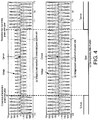
- FIG 4 A result of simulation of a compensation operation at the time of momentary power interruption of the power supply system 100 having the configuration illustrated in FIG. 1 is illustrated in FIG 4 .
- the result of simulation of a compensation operation represents (a) voltage/current waveforms of the commercial power system side, (b) voltage/current waveforms of a consumer side, and (c) opening/closing of the changeover switch when a voltage drop of 50% is maintained for 0.35 seconds.
- the voltage/current waveforms of the commercial power system side indicate a voltage and a current which are detected in a part closer to the commercial power system than to the changeover switch in the power line
- the voltage/current waveforms of the consumer side indicate a voltage and a current which are detected in a part closer to the important load than to the distributed power supply in the power line.
- the reactor 4 is connected in parallel to the changeover switch 3, and the changeover switch 3 is opened when the voltage of the commercial power system 10 side becomes equal to or lower than the set value, the distributed power supply 2 and the important load 30 are connected to the commercial power system 10 via the reactor 4 even at the time of occurrence of momentary power interruption.
- the distributed power supply 2 and the important load 30 are not disconnected from the commercial power system 10 at the time of normal operation and at the time of momentary power interruption, it is possible to prevent a voltage drop in the important load 30 at the time of momentary power interruption while satisfying the FRT requirements of the distributed power supply 2.
- a novel power supply system 100 that can perform both an uninterruptible power supply function and a load leveling function using a common distributed power supply 2 while satisfying the FRT requirements.
- the power supply system 100 satisfies FRT requirements for a frequency variation in addition to the FRT requirements for a voltage drop in the first embodiment.
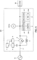
- the power supply system 100 includes a frequency variation detecting unit 7 that detects a frequency variation in a part closer to the commercial power system 10 than to the changeover switch 3 in addition to the configuration according to the first embodiment as illustrated in FIG. 5 .
- the frequency variation detecting unit 7 serves to detect a frequency variation (a frequency increase (OF) or a frequency decrease (UF)) from the voltage detected by the system-side voltage detecting unit 5.
- the control unit 6 controls opening and closing of the changeover switch 3 on the basis of the frequency variation detected by the frequency variation detecting unit 7.
- This frequency variation is, for example, a stepwise increase or a ramp-like increase or decrease.
- the frequency electric detecting unit 7 detects the frequency variation of the commercial power system 10 regardless of opening or closing of the changeover switch 3, and the control unit 6 closes the changeover switch 3 when the frequency variation of the commercial power system 10 becomes less than the smaller frequency tolerance.
- a disconnection switch 8 is provided closer to the commercial power system 10 than to the distributed power supply 2 in the power line L1 as illustrated in FIG. 8 .
- a power-supply-side voltage detecting unit 9 that detects a voltage of a part closer to the distributed power supply 2 than to the disconnection switch 8 in the power line L1 is provided.
- the disconnection switch 8 in this embodiment is an on-off switch that disconnects the commercial power system 10 and the distributed power supply 2 and is, for example, a mechanical switch.
- the disconnection switch 8 is provided closer to the commercial power system 10 than to the changeover switch 3, but may be provided closer to the distributed power supply 2 than to the changeover switch 3. Opening and closing of the disconnection switch 8 is controlled by the control unit 6.
- the control unit 6 opens the disconnection switch 8.
- the predetermined disconnection condition is a condition that a duration time of a voltage drop of the system voltage (a state in which the detected voltage is equal to or less than the set value) is equal to or greater than a predetermined value (a time which is longer than a duration time of momentary power interruption).
- the distributed power supply 2 enters a self-operation mode and supplies electric power to the important load 30. Since the changeover switch 3 is already open, an overcurrent due to opening of the disconnection switch 8 is curbed by the reactor 4.
- the control unit 6 turns on the disconnection switch 8.
- the control unit 6 when a predetermined disconnection condition such as a condition that the frequency variation detected by the frequency variation detecting unit 7 departs from the frequency range of the FRT requirements is satisfied, the control unit 6 also opens the disconnection switch 8. At this time, the control unit turns on the disconnection switch 8 when the detected frequency electric is within the normal range.
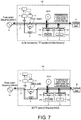
- the important load 30 includes a motor 30a and a power-factor improvement capacitor 30b that is connected in parallel to the motor 30a as illustrated in FIG. 11 .
- a resistor is used as the impedance element 4.
- opening and closing control of the changeover switch 3 at the time of normal operation and at the time of momentary power interruption is the same as in the above-mentioned embodiments.
- a current flows in the resistor at the time of opening of the changeover switch, but since the time in which the changeover switch 3 is open is only several seconds, it is not necessary to cope with a thermal loss due to the resistor.
- a capacitor may be used as the impedance element 4, or a combination of two of a reactor, a resistor, and a capacitor may be used.
- the system-side voltage detecting unit in the above-mentioned embodiments may be provided in a system-connection protection device.
- the system-connection protection device which is defined in system connection regulations include an overvoltage relay (OVR), an undervoltage relay (UVR), a short-circuit direction relay (DSR), a ground-fault overvoltage relay (OVGR), an overfrequency relay (OFR), an underfrequency relay (UFR), and a transfer interrupting device.
- OVR overvoltage relay
- UVR undervoltage relay
- DSR short-circuit direction relay
- OVGR ground-fault overvoltage relay
- OFR overfrequency relay
- UFR underfrequency relay
- transfer interrupting device it is conceivable that the control unit opens the disconnection switch when any connection protection instrument operates.
- the control unit may turn on the disconnection switch.
- the power-supply-side voltage detecting unit in the above-mentioned embodiments is provided between the disconnection switch and the changeover switch and may be replaced by a function of measuring a system connection point voltage of the distributed power supply.
Landscapes
- Engineering & Computer Science (AREA)
- Power Engineering (AREA)
- Business, Economics & Management (AREA)
- Emergency Management (AREA)
- Supply And Distribution Of Alternating Current (AREA)
- Stand-By Power Supply Arrangements (AREA)
- Charge And Discharge Circuits For Batteries Or The Like (AREA)
Applications Claiming Priority (2)
| Application Number | Priority Date | Filing Date | Title |
|---|---|---|---|
| JP2017169664A JP6338131B1 (ja) | 2017-09-04 | 2017-09-04 | 電源システム |
| PCT/JP2018/031601 WO2019044774A1 (fr) | 2017-09-04 | 2018-08-27 | Système d'alimentation électrique |
Publications (3)
| Publication Number | Publication Date |
|---|---|
| EP3681008A1 true EP3681008A1 (fr) | 2020-07-15 |
| EP3681008A4 EP3681008A4 (fr) | 2021-03-10 |
| EP3681008B1 EP3681008B1 (fr) | 2022-09-21 |
Family
ID=62487333
Family Applications (1)
| Application Number | Title | Priority Date | Filing Date |
|---|---|---|---|
| EP18852678.4A Active EP3681008B1 (fr) | 2017-09-04 | 2018-08-27 | Système d'alimentation électrique |
Country Status (7)
| Country | Link |
|---|---|
| US (1) | US11196293B2 (fr) |
| EP (1) | EP3681008B1 (fr) |
| JP (1) | JP6338131B1 (fr) |
| CN (1) | CN111052529B (fr) |
| AU (1) | AU2018323422B2 (fr) |
| TW (1) | TWI669877B (fr) |
| WO (1) | WO2019044774A1 (fr) |
Families Citing this family (23)
| Publication number | Priority date | Publication date | Assignee | Title |
|---|---|---|---|---|
| JP2020018028A (ja) * | 2018-07-23 | 2020-01-30 | 日新電機株式会社 | 電源システム |
| EP3832831A4 (fr) * | 2018-07-27 | 2022-03-30 | Nissin Electric Co., Ltd. | Système d'alimentation électrique |
| JP7265701B2 (ja) * | 2019-03-27 | 2023-04-27 | 日新電機株式会社 | 電源システム |
| JP7265702B2 (ja) * | 2019-03-27 | 2023-04-27 | 日新電機株式会社 | 電源システム |
| CN113906647B (zh) | 2019-07-01 | 2024-07-02 | 日新电机株式会社 | 不断电电源装置 |
| WO2021033299A1 (fr) | 2019-08-22 | 2021-02-25 | 日新電機株式会社 | Appareil d'alimentation électrique et procédé de commande d'appareil d'alimentation électrique |
| TWI710207B (zh) * | 2019-08-23 | 2020-11-11 | 日商日新電機股份有限公司 | 電源裝置以及電源裝置的控制方法 |
| JP7440752B2 (ja) * | 2020-02-21 | 2024-02-29 | 日新電機株式会社 | 電源システム |
| CN111461520B (zh) * | 2020-03-27 | 2022-04-19 | 广东电网有限责任公司 | 一种配网线路自动开关分布智能分析方法 |
| JP7523735B2 (ja) * | 2020-06-11 | 2024-07-29 | 日新電機株式会社 | 電源システム |
| JP7523736B2 (ja) * | 2020-06-25 | 2024-07-29 | 日新電機株式会社 | 電源システム |
| JP7542181B2 (ja) * | 2020-08-26 | 2024-08-30 | 日新電機株式会社 | 移動体を用いた電力供給システム |
| JP7542179B2 (ja) * | 2020-08-26 | 2024-08-30 | 日新電機株式会社 | 電源システム |
| JP7542180B2 (ja) * | 2020-08-26 | 2024-08-30 | 日新電機株式会社 | 無停電電源システム |
| JP7659162B2 (ja) * | 2021-01-14 | 2025-04-09 | 日新電機株式会社 | 電源システム |
| JP7659163B2 (ja) * | 2021-01-14 | 2025-04-09 | 日新電機株式会社 | 電源システム |
| JP7623578B2 (ja) * | 2021-03-08 | 2025-01-29 | 日新電機株式会社 | 電源システム |
| JP7807634B2 (ja) * | 2021-09-02 | 2026-01-28 | 日新電機株式会社 | 電源システム |
| CN114336940B (zh) * | 2021-12-30 | 2024-05-31 | 广电计量检测(成都)有限公司 | 一种用于产品测试的电源稳定装置 |
| JP7787407B2 (ja) * | 2022-02-21 | 2025-12-17 | 日新電機株式会社 | 双方向型電源システム |
| US11942818B2 (en) * | 2022-03-29 | 2024-03-26 | Schneider Electric It Corporation | Arrangement of converters and fast switches to provide BESS and UPS combined function |
| US11888344B2 (en) | 2022-04-26 | 2024-01-30 | Schneider Electric It Corporation | Reversed power and grid support with a modular approach |
| JP7560754B2 (ja) * | 2022-08-29 | 2024-10-03 | 日新電機株式会社 | 電源システム及び電源システムの制御方法 |
Family Cites Families (20)
| Publication number | Priority date | Publication date | Assignee | Title |
|---|---|---|---|---|
| JPS5066130A (fr) | 1973-10-11 | 1975-06-04 | ||
| JPS5066130U (fr) * | 1973-10-17 | 1975-06-14 | ||
| US4686382A (en) * | 1985-08-14 | 1987-08-11 | Westinghouse Electric Corp. | Switch bypass circuit for power line communication systems |
| JP3402886B2 (ja) | 1995-12-26 | 2003-05-06 | 東京電力株式会社 | 分散型電源設備 |
| US5994794A (en) * | 1997-05-09 | 1999-11-30 | Active Power, Inc. | Methods and apparatus for providing protection to batteries in an uninterruptible power supply |
| JP2000184602A (ja) * | 1998-12-11 | 2000-06-30 | Nissin Electric Co Ltd | 分散型電源装置 |
| US6134124A (en) * | 1999-05-12 | 2000-10-17 | Abb Power T&D Company Inc. | Universal distributed-resource interface |
| JP4008372B2 (ja) | 2003-03-25 | 2007-11-14 | 日本碍子株式会社 | 負荷平準化機能及び無停電電源機能を併せ持つ高温作動型二次電池システム |
| US7391132B2 (en) * | 2004-12-03 | 2008-06-24 | Huei-Jung Chen | Methods and apparatus providing double conversion/series-parallel hybrid operation in uninterruptible power supplies |
| JP5497115B2 (ja) * | 2012-01-27 | 2014-05-21 | 三菱電機株式会社 | 電源切替装置及び配電盤 |
| EP2662878A1 (fr) * | 2012-05-08 | 2013-11-13 | GE Energy Power Conversion Technology Limited | Ensembles de commutation à vide |
| US9048039B2 (en) * | 2012-05-08 | 2015-06-02 | Ge Energy Power Conversion Technology Limited | Vacuum switch assemblies |
| CN103683356B (zh) * | 2012-09-20 | 2015-10-21 | 伊顿制造(格拉斯哥)有限合伙莫尔日分支机构 | 在线式不间断电源拓扑 |
| JP2014082867A (ja) * | 2012-10-16 | 2014-05-08 | Toshiba Corp | 電源制御システム、制御装置及び制御方法 |
| CN102969742A (zh) * | 2012-12-18 | 2013-03-13 | 天津工业大学 | 多功能光伏发电实验系统及其控制方法 |
| JP6351331B2 (ja) * | 2014-03-28 | 2018-07-04 | 株式会社東芝 | 電力変換装置 |
| JP2016059168A (ja) * | 2014-09-09 | 2016-04-21 | 富士電機株式会社 | 母線電圧安定化装置 |
| JP2016208586A (ja) * | 2015-04-16 | 2016-12-08 | 株式会社東芝 | 電力システムにおける事故安定化装置及びその方法 |
| JP6599700B2 (ja) * | 2015-09-08 | 2019-10-30 | マクセルホールディングス株式会社 | 系統連系装置 |
| US10211670B2 (en) * | 2015-12-22 | 2019-02-19 | Schneider Electric It Corporation | UPS with integrated bypass switch |
-
2017
- 2017-09-04 JP JP2017169664A patent/JP6338131B1/ja active Active
-
2018
- 2018-08-27 EP EP18852678.4A patent/EP3681008B1/fr active Active
- 2018-08-27 AU AU2018323422A patent/AU2018323422B2/en active Active
- 2018-08-27 US US16/643,851 patent/US11196293B2/en active Active
- 2018-08-27 WO PCT/JP2018/031601 patent/WO2019044774A1/fr not_active Ceased
- 2018-08-27 CN CN201880056896.1A patent/CN111052529B/zh active Active
- 2018-09-03 TW TW107130765A patent/TWI669877B/zh active
Also Published As
| Publication number | Publication date |
|---|---|
| AU2018323422B2 (en) | 2020-09-03 |
| CN111052529B (zh) | 2023-08-15 |
| TW201921825A (zh) | 2019-06-01 |
| TWI669877B (zh) | 2019-08-21 |
| EP3681008B1 (fr) | 2022-09-21 |
| EP3681008A4 (fr) | 2021-03-10 |
| JP2019047656A (ja) | 2019-03-22 |
| US11196293B2 (en) | 2021-12-07 |
| US20210066958A1 (en) | 2021-03-04 |
| WO2019044774A1 (fr) | 2019-03-07 |
| AU2018323422A1 (en) | 2020-03-19 |
| JP6338131B1 (ja) | 2018-06-06 |
| CN111052529A (zh) | 2020-04-21 |
Similar Documents
| Publication | Publication Date | Title |
|---|---|---|
| AU2018323422B2 (en) | Power supply system | |
| JP7017116B2 (ja) | 電源システム | |
| CN104730406B (zh) | 逆变器和用于检测在供能网络中的断相的方法 | |
| EP3010110B1 (fr) | Système de génération de puissance photovoltaique attaché au réseau | |
| US10951057B1 (en) | Reliable power module for improved substation device availability | |
| CN112106273A (zh) | 不断电电源装置 | |
| JP2015053842A (ja) | 分散電源の接続装置 | |
| EP3654480B1 (fr) | Conditionneur de puissance, système de puissance et procédé de supression de puissance réactive de système de puissance | |
| CN104124697B (zh) | 一种无功自动补偿系统 | |
| JP7328544B2 (ja) | 電源システム | |
| JP7523736B2 (ja) | 電源システム | |
| CN106655461B (zh) | 不断电供电系统 | |
| RU151864U1 (ru) | Система электроснабжения собственных нужд электростанции | |
| JP7617510B2 (ja) | 電源システム | |
| JP7542181B2 (ja) | 移動体を用いた電力供給システム | |
| JP7623578B2 (ja) | 電源システム | |
| JP5707184B2 (ja) | 配電システム | |
| JP7807634B2 (ja) | 電源システム | |
| JP7542179B2 (ja) | 電源システム | |
| JP7523735B2 (ja) | 電源システム | |
| JP2024073768A (ja) | 無停電電源装置 | |
| JP2004201413A (ja) | 電力貯蔵システム | |
| JP2016158337A (ja) | 電力供給システム |
Legal Events
| Date | Code | Title | Description |
|---|---|---|---|
| STAA | Information on the status of an ep patent application or granted ep patent |
Free format text: STATUS: THE INTERNATIONAL PUBLICATION HAS BEEN MADE |
|
| PUAI | Public reference made under article 153(3) epc to a published international application that has entered the european phase |
Free format text: ORIGINAL CODE: 0009012 |
|
| STAA | Information on the status of an ep patent application or granted ep patent |
Free format text: STATUS: REQUEST FOR EXAMINATION WAS MADE |
|
| 17P | Request for examination filed |
Effective date: 20200224 |
|
| AK | Designated contracting states |
Kind code of ref document: A1 Designated state(s): AL AT BE BG CH CY CZ DE DK EE ES FI FR GB GR HR HU IE IS IT LI LT LU LV MC MK MT NL NO PL PT RO RS SE SI SK SM TR |
|
| AX | Request for extension of the european patent |
Extension state: BA ME |
|
| RIN1 | Information on inventor provided before grant (corrected) |
Inventor name: UDA, SATOSHI Inventor name: NISHIMURA, SHOJI Inventor name: KAWASAKI, YOSHINORI |
|
| DAV | Request for validation of the european patent (deleted) | ||
| DAX | Request for extension of the european patent (deleted) | ||
| A4 | Supplementary search report drawn up and despatched |
Effective date: 20210208 |
|
| RIC1 | Information provided on ipc code assigned before grant |
Ipc: H02J 7/32 20060101ALN20210202BHEP Ipc: H02J 3/24 20060101ALI20210202BHEP Ipc: H02J 3/38 20060101AFI20210202BHEP Ipc: H02J 9/06 20060101ALI20210202BHEP |
|
| GRAP | Despatch of communication of intention to grant a patent |
Free format text: ORIGINAL CODE: EPIDOSNIGR1 |
|
| STAA | Information on the status of an ep patent application or granted ep patent |
Free format text: STATUS: GRANT OF PATENT IS INTENDED |
|
| RIC1 | Information provided on ipc code assigned before grant |
Ipc: H02J 7/32 20060101ALN20220429BHEP Ipc: H02J 9/06 20060101ALI20220429BHEP Ipc: H02J 3/24 20060101ALI20220429BHEP Ipc: H02J 3/38 20060101AFI20220429BHEP |
|
| RIC1 | Information provided on ipc code assigned before grant |
Ipc: H02J 3/32 20060101ALN20220517BHEP Ipc: H02J 9/06 20060101ALI20220517BHEP Ipc: H02J 3/24 20060101ALI20220517BHEP Ipc: H02J 3/38 20060101AFI20220517BHEP |
|
| RIC1 | Information provided on ipc code assigned before grant |
Ipc: H02J 3/32 20060101ALN20220525BHEP Ipc: H02J 9/06 20060101ALI20220525BHEP Ipc: H02J 3/24 20060101ALI20220525BHEP Ipc: H02J 3/38 20060101AFI20220525BHEP |
|
| INTG | Intention to grant announced |
Effective date: 20220607 |
|
| GRAS | Grant fee paid |
Free format text: ORIGINAL CODE: EPIDOSNIGR3 |
|
| GRAA | (expected) grant |
Free format text: ORIGINAL CODE: 0009210 |
|
| STAA | Information on the status of an ep patent application or granted ep patent |
Free format text: STATUS: THE PATENT HAS BEEN GRANTED |
|
| AK | Designated contracting states |
Kind code of ref document: B1 Designated state(s): AL AT BE BG CH CY CZ DE DK EE ES FI FR GB GR HR HU IE IS IT LI LT LU LV MC MK MT NL NO PL PT RO RS SE SI SK SM TR |
|
| REG | Reference to a national code |
Ref country code: GB Ref legal event code: FG4D |
|
| REG | Reference to a national code |
Ref country code: CH Ref legal event code: EP |
|
| REG | Reference to a national code |
Ref country code: IE Ref legal event code: FG4D |
|
| REG | Reference to a national code |
Ref country code: DE Ref legal event code: R096 Ref document number: 602018040983 Country of ref document: DE |
|
| REG | Reference to a national code |
Ref country code: AT Ref legal event code: REF Ref document number: 1520450 Country of ref document: AT Kind code of ref document: T Effective date: 20221015 |
|
| REG | Reference to a national code |
Ref country code: SE Ref legal event code: TRGR |
|
| REG | Reference to a national code |
Ref country code: LT Ref legal event code: MG9D |
|
| REG | Reference to a national code |
Ref country code: NL Ref legal event code: MP Effective date: 20220921 |
|
| PG25 | Lapsed in a contracting state [announced via postgrant information from national office to epo] |
Ref country code: RS Free format text: LAPSE BECAUSE OF FAILURE TO SUBMIT A TRANSLATION OF THE DESCRIPTION OR TO PAY THE FEE WITHIN THE PRESCRIBED TIME-LIMIT Effective date: 20220921 Ref country code: NO Free format text: LAPSE BECAUSE OF FAILURE TO SUBMIT A TRANSLATION OF THE DESCRIPTION OR TO PAY THE FEE WITHIN THE PRESCRIBED TIME-LIMIT Effective date: 20221221 Ref country code: LV Free format text: LAPSE BECAUSE OF FAILURE TO SUBMIT A TRANSLATION OF THE DESCRIPTION OR TO PAY THE FEE WITHIN THE PRESCRIBED TIME-LIMIT Effective date: 20220921 Ref country code: LT Free format text: LAPSE BECAUSE OF FAILURE TO SUBMIT A TRANSLATION OF THE DESCRIPTION OR TO PAY THE FEE WITHIN THE PRESCRIBED TIME-LIMIT Effective date: 20220921 Ref country code: FI Free format text: LAPSE BECAUSE OF FAILURE TO SUBMIT A TRANSLATION OF THE DESCRIPTION OR TO PAY THE FEE WITHIN THE PRESCRIBED TIME-LIMIT Effective date: 20220921 |
|
| REG | Reference to a national code |
Ref country code: AT Ref legal event code: MK05 Ref document number: 1520450 Country of ref document: AT Kind code of ref document: T Effective date: 20220921 |
|
| PG25 | Lapsed in a contracting state [announced via postgrant information from national office to epo] |
Ref country code: HR Free format text: LAPSE BECAUSE OF FAILURE TO SUBMIT A TRANSLATION OF THE DESCRIPTION OR TO PAY THE FEE WITHIN THE PRESCRIBED TIME-LIMIT Effective date: 20220921 Ref country code: GR Free format text: LAPSE BECAUSE OF FAILURE TO SUBMIT A TRANSLATION OF THE DESCRIPTION OR TO PAY THE FEE WITHIN THE PRESCRIBED TIME-LIMIT Effective date: 20221222 |
|
| PG25 | Lapsed in a contracting state [announced via postgrant information from national office to epo] |
Ref country code: SM Free format text: LAPSE BECAUSE OF FAILURE TO SUBMIT A TRANSLATION OF THE DESCRIPTION OR TO PAY THE FEE WITHIN THE PRESCRIBED TIME-LIMIT Effective date: 20220921 Ref country code: RO Free format text: LAPSE BECAUSE OF FAILURE TO SUBMIT A TRANSLATION OF THE DESCRIPTION OR TO PAY THE FEE WITHIN THE PRESCRIBED TIME-LIMIT Effective date: 20220921 Ref country code: PT Free format text: LAPSE BECAUSE OF FAILURE TO SUBMIT A TRANSLATION OF THE DESCRIPTION OR TO PAY THE FEE WITHIN THE PRESCRIBED TIME-LIMIT Effective date: 20230123 Ref country code: ES Free format text: LAPSE BECAUSE OF FAILURE TO SUBMIT A TRANSLATION OF THE DESCRIPTION OR TO PAY THE FEE WITHIN THE PRESCRIBED TIME-LIMIT Effective date: 20220921 Ref country code: CZ Free format text: LAPSE BECAUSE OF FAILURE TO SUBMIT A TRANSLATION OF THE DESCRIPTION OR TO PAY THE FEE WITHIN THE PRESCRIBED TIME-LIMIT Effective date: 20220921 Ref country code: AT Free format text: LAPSE BECAUSE OF FAILURE TO SUBMIT A TRANSLATION OF THE DESCRIPTION OR TO PAY THE FEE WITHIN THE PRESCRIBED TIME-LIMIT Effective date: 20220921 |
|
| PG25 | Lapsed in a contracting state [announced via postgrant information from national office to epo] |
Ref country code: SK Free format text: LAPSE BECAUSE OF FAILURE TO SUBMIT A TRANSLATION OF THE DESCRIPTION OR TO PAY THE FEE WITHIN THE PRESCRIBED TIME-LIMIT Effective date: 20220921 Ref country code: PL Free format text: LAPSE BECAUSE OF FAILURE TO SUBMIT A TRANSLATION OF THE DESCRIPTION OR TO PAY THE FEE WITHIN THE PRESCRIBED TIME-LIMIT Effective date: 20220921 Ref country code: IS Free format text: LAPSE BECAUSE OF FAILURE TO SUBMIT A TRANSLATION OF THE DESCRIPTION OR TO PAY THE FEE WITHIN THE PRESCRIBED TIME-LIMIT Effective date: 20230121 Ref country code: EE Free format text: LAPSE BECAUSE OF FAILURE TO SUBMIT A TRANSLATION OF THE DESCRIPTION OR TO PAY THE FEE WITHIN THE PRESCRIBED TIME-LIMIT Effective date: 20220921 |
|
| REG | Reference to a national code |
Ref country code: DE Ref legal event code: R097 Ref document number: 602018040983 Country of ref document: DE |
|
| PG25 | Lapsed in a contracting state [announced via postgrant information from national office to epo] |
Ref country code: NL Free format text: LAPSE BECAUSE OF FAILURE TO SUBMIT A TRANSLATION OF THE DESCRIPTION OR TO PAY THE FEE WITHIN THE PRESCRIBED TIME-LIMIT Effective date: 20220921 Ref country code: AL Free format text: LAPSE BECAUSE OF FAILURE TO SUBMIT A TRANSLATION OF THE DESCRIPTION OR TO PAY THE FEE WITHIN THE PRESCRIBED TIME-LIMIT Effective date: 20220921 |
|
| PLBE | No opposition filed within time limit |
Free format text: ORIGINAL CODE: 0009261 |
|
| STAA | Information on the status of an ep patent application or granted ep patent |
Free format text: STATUS: NO OPPOSITION FILED WITHIN TIME LIMIT |
|
| PG25 | Lapsed in a contracting state [announced via postgrant information from national office to epo] |
Ref country code: DK Free format text: LAPSE BECAUSE OF FAILURE TO SUBMIT A TRANSLATION OF THE DESCRIPTION OR TO PAY THE FEE WITHIN THE PRESCRIBED TIME-LIMIT Effective date: 20220921 |
|
| 26N | No opposition filed |
Effective date: 20230622 |
|
| PG25 | Lapsed in a contracting state [announced via postgrant information from national office to epo] |
Ref country code: SI Free format text: LAPSE BECAUSE OF FAILURE TO SUBMIT A TRANSLATION OF THE DESCRIPTION OR TO PAY THE FEE WITHIN THE PRESCRIBED TIME-LIMIT Effective date: 20220921 |
|
| PG25 | Lapsed in a contracting state [announced via postgrant information from national office to epo] |
Ref country code: MC Free format text: LAPSE BECAUSE OF FAILURE TO SUBMIT A TRANSLATION OF THE DESCRIPTION OR TO PAY THE FEE WITHIN THE PRESCRIBED TIME-LIMIT Effective date: 20220921 |
|
| PG25 | Lapsed in a contracting state [announced via postgrant information from national office to epo] |
Ref country code: MC Free format text: LAPSE BECAUSE OF FAILURE TO SUBMIT A TRANSLATION OF THE DESCRIPTION OR TO PAY THE FEE WITHIN THE PRESCRIBED TIME-LIMIT Effective date: 20220921 |
|
| PG25 | Lapsed in a contracting state [announced via postgrant information from national office to epo] |
Ref country code: LU Free format text: LAPSE BECAUSE OF NON-PAYMENT OF DUE FEES Effective date: 20230827 |
|
| GBPC | Gb: european patent ceased through non-payment of renewal fee |
Effective date: 20230827 |
|
| PG25 | Lapsed in a contracting state [announced via postgrant information from national office to epo] |
Ref country code: LU Free format text: LAPSE BECAUSE OF NON-PAYMENT OF DUE FEES Effective date: 20230827 |
|
| REG | Reference to a national code |
Ref country code: BE Ref legal event code: MM Effective date: 20230831 |
|
| REG | Reference to a national code |
Ref country code: IE Ref legal event code: MM4A |
|
| PG25 | Lapsed in a contracting state [announced via postgrant information from national office to epo] |
Ref country code: IT Free format text: LAPSE BECAUSE OF FAILURE TO SUBMIT A TRANSLATION OF THE DESCRIPTION OR TO PAY THE FEE WITHIN THE PRESCRIBED TIME-LIMIT Effective date: 20220921 |
|
| PG25 | Lapsed in a contracting state [announced via postgrant information from national office to epo] |
Ref country code: IE Free format text: LAPSE BECAUSE OF NON-PAYMENT OF DUE FEES Effective date: 20230827 |
|
| PG25 | Lapsed in a contracting state [announced via postgrant information from national office to epo] |
Ref country code: GB Free format text: LAPSE BECAUSE OF NON-PAYMENT OF DUE FEES Effective date: 20230827 |
|
| PG25 | Lapsed in a contracting state [announced via postgrant information from national office to epo] |
Ref country code: IE Free format text: LAPSE BECAUSE OF NON-PAYMENT OF DUE FEES Effective date: 20230827 Ref country code: GB Free format text: LAPSE BECAUSE OF NON-PAYMENT OF DUE FEES Effective date: 20230827 |
|
| PG25 | Lapsed in a contracting state [announced via postgrant information from national office to epo] |
Ref country code: BE Free format text: LAPSE BECAUSE OF NON-PAYMENT OF DUE FEES Effective date: 20230831 |
|
| PG25 | Lapsed in a contracting state [announced via postgrant information from national office to epo] |
Ref country code: BG Free format text: LAPSE BECAUSE OF FAILURE TO SUBMIT A TRANSLATION OF THE DESCRIPTION OR TO PAY THE FEE WITHIN THE PRESCRIBED TIME-LIMIT Effective date: 20220921 |
|
| PG25 | Lapsed in a contracting state [announced via postgrant information from national office to epo] |
Ref country code: BG Free format text: LAPSE BECAUSE OF FAILURE TO SUBMIT A TRANSLATION OF THE DESCRIPTION OR TO PAY THE FEE WITHIN THE PRESCRIBED TIME-LIMIT Effective date: 20220921 |
|
| PGFP | Annual fee paid to national office [announced via postgrant information from national office to epo] |
Ref country code: FR Payment date: 20250630 Year of fee payment: 8 |
|
| PG25 | Lapsed in a contracting state [announced via postgrant information from national office to epo] |
Ref country code: CY Free format text: LAPSE BECAUSE OF FAILURE TO SUBMIT A TRANSLATION OF THE DESCRIPTION OR TO PAY THE FEE WITHIN THE PRESCRIBED TIME-LIMIT; INVALID AB INITIO Effective date: 20180827 |
|
| PG25 | Lapsed in a contracting state [announced via postgrant information from national office to epo] |
Ref country code: HU Free format text: LAPSE BECAUSE OF FAILURE TO SUBMIT A TRANSLATION OF THE DESCRIPTION OR TO PAY THE FEE WITHIN THE PRESCRIBED TIME-LIMIT; INVALID AB INITIO Effective date: 20180827 |
|
| PGFP | Annual fee paid to national office [announced via postgrant information from national office to epo] |
Ref country code: DE Payment date: 20250826 Year of fee payment: 8 |
|
| PGFP | Annual fee paid to national office [announced via postgrant information from national office to epo] |
Ref country code: CH Payment date: 20250901 Year of fee payment: 8 Ref country code: SE Payment date: 20250715 Year of fee payment: 8 |
|
| PG25 | Lapsed in a contracting state [announced via postgrant information from national office to epo] |
Ref country code: TR Free format text: LAPSE BECAUSE OF FAILURE TO SUBMIT A TRANSLATION OF THE DESCRIPTION OR TO PAY THE FEE WITHIN THE PRESCRIBED TIME-LIMIT Effective date: 20220921 |