EP3681020B1 - Ensembles de résistances rotatives - Google Patents
Ensembles de résistances rotatives Download PDFInfo
- Publication number
- EP3681020B1 EP3681020B1 EP19209828.3A EP19209828A EP3681020B1 EP 3681020 B1 EP3681020 B1 EP 3681020B1 EP 19209828 A EP19209828 A EP 19209828A EP 3681020 B1 EP3681020 B1 EP 3681020B1
- Authority
- EP
- European Patent Office
- Prior art keywords
- housing
- assembly
- bus bar
- aperture
- rotor
- Prior art date
- Legal status (The legal status is an assumption and is not a legal conclusion. Google has not performed a legal analysis and makes no representation as to the accuracy of the status listed.)
- Active
Links
Images
Classifications
-
- H—ELECTRICITY
- H02—GENERATION; CONVERSION OR DISTRIBUTION OF ELECTRIC POWER
- H02K—DYNAMO-ELECTRIC MACHINES
- H02K11/00—Structural association of dynamo-electric machines with electric components or with devices for shielding, monitoring or protection
- H02K11/0094—Structural association with other electrical or electronic devices
-
- H—ELECTRICITY
- H02—GENERATION; CONVERSION OR DISTRIBUTION OF ELECTRIC POWER
- H02K—DYNAMO-ELECTRIC MACHINES
- H02K11/00—Structural association of dynamo-electric machines with electric components or with devices for shielding, monitoring or protection
- H02K11/04—Structural association of dynamo-electric machines with electric components or with devices for shielding, monitoring or protection for rectification
- H02K11/042—Rectifiers associated with rotating parts, e.g. rotor cores or rotary shafts
-
- H—ELECTRICITY
- H01—ELECTRIC ELEMENTS
- H01C—RESISTORS
- H01C1/00—Details
- H01C1/02—Housing; Enclosing; Embedding; Filling the housing or enclosure
-
- H—ELECTRICITY
- H01—ELECTRIC ELEMENTS
- H01C—RESISTORS
- H01C13/00—Resistors not provided for elsewhere
- H01C13/02—Structural combinations of resistors
-
- H—ELECTRICITY
- H02—GENERATION; CONVERSION OR DISTRIBUTION OF ELECTRIC POWER
- H02K—DYNAMO-ELECTRIC MACHINES
- H02K19/00—Synchronous motors or generators
- H02K19/16—Synchronous generators
- H02K19/36—Structural association of synchronous generators with auxiliary electric devices influencing the characteristic of the generator or controlling the generator, e.g. with impedances or switches
-
- H—ELECTRICITY
- H02—GENERATION; CONVERSION OR DISTRIBUTION OF ELECTRIC POWER
- H02K—DYNAMO-ELECTRIC MACHINES
- H02K7/00—Arrangements for handling mechanical energy structurally associated with dynamo-electric machines, e.g. structural association with mechanical driving motors or auxiliary dynamo-electric machines
- H02K7/003—Couplings; Details of shafts
-
- H—ELECTRICITY
- H02—GENERATION; CONVERSION OR DISTRIBUTION OF ELECTRIC POWER
- H02M—APPARATUS FOR CONVERSION BETWEEN AC AND AC, BETWEEN AC AND DC, OR BETWEEN DC AND DC, AND FOR USE WITH MAINS OR SIMILAR POWER SUPPLY SYSTEMS; CONVERSION OF DC OR AC INPUT POWER INTO SURGE OUTPUT POWER; CONTROL OR REGULATION THEREOF
- H02M7/00—Conversion of AC power input into DC power output; Conversion of DC power input into AC power output
- H02M7/003—Constructional details, e.g. physical layout, assembly, wiring or busbar connections
Definitions
- This disclosure relates to rotating resistor assemblies, e.g., for use in a shaft of a generator.
- Certain generators take advantage of three stages, including a permanent magnet stage, an exciter stage, and a main stage.
- the exciter stage can include an exciter stator winding for receiving DC power that energizes the exciter stator and generates a magnetic field. Rotational energy provided by the shaft causes the exciter rotor to move through the magnetic field, resulting in the generation of alternating current (AC) electric power in the exciter rotor.
- a rotating rectifier assembly can be mounted within the rotor for converting the AC power to a direct current (DC) electric power that is supplied to the main rotor winding.
- the DC power provided to the rotating main rotor winding results in a rotating magnetic field that generates AC power in the stator windings of the main stage producing power output.
- the assembly In order for the rotating rectifier to be connected to the main field of the rotor, the assembly requires a connection assembly.
- certain systems include a rotating resistor assembly within the shaft electrically connected to the rotating rectifier to act as the connection assembly.
- Existing rotating resistor assemblies include many components and include certain components that are manufactured from a solid bar of beryllium copper, which is both environmentally hazardous and costly. Additionally, existing rotating resistor assemblies require that the main field leads be soldered to the rotating resistor assembly, which creates a structural weak point in the generator.
- Existing systems also use a high impedance resistor used to provide a grounding path in the rotor, and this is traditionally a ceramic resistance and prone to cracking which can break the grounding path.
- a rotating resistor assembly for use in a rotating shaft of an electrical machine is given in claim 1.
- the first housing can be made of metal or any other suitable material.
- the first housing can be made of aluminum.
- the second housing is made of metal and includes a coating such that direct contact with the shaft (and/or the first housing) does not electrically connect the shaft to the second housing (and/or the second housing to the first housing).
- the metal can be aluminum and the coating is a dielectric. Any other suitable material for the second housing (e.g., uncoated ceramic) and/or any coating thereof is contemplated herein.
- An insulating washer can be disposed between and in contact with the first housing and the second housing, e.g., to at least provide abrasion resistance to protect the coating of the second housing (and/or additional electrical insulation).
- the insulating washer can be made of polyimide film.
- the second housing can include a radial aperture defined from a center of the second housing to an outer surface of the second housing.
- the first housing can include a tab extending axially therefrom. The tab can define the first bus bar connection aperture and can be configured to insert into the radial aperture of the second housing, e.g., to axially align the first bus bar aperture and the second bus bar aperture.
- the suppression resistor can be at least partially (e.g., fully) encased within the first housing and the second housing.
- the suppression resistor can be a ceramic hollow cylinder.
- the assembly can include a first bus bar disposed in the first bus bar aperture and a second bus bar inserted in the second bus bar aperture.
- a rotor assembly for an electrical machine can include a rotor, a rectifier diode pack disposed in the rotor, and a rotating resistor assembly disposed in the rotor and in electrical communication with the rectifier diode pack.
- the rotating resistor assembly can be any suitable assembly as disclosed herein.
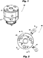
- FIG. 1 an illustrative view of an embodiment of an assembly in accordance with the disclosure is shown in Fig. 1 and is designated generally by reference character 100.
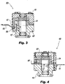
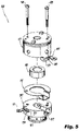
- FIG. 2-5 Other embodiments and/or aspects of this disclosure are shown in Figs. 2-5 .
- Certain embodiments described herein can be used as a resistor assembly for an electrical machine having rotating diodes, for example, or for any other suitable use.
- a rotating resistor assembly 100 e.g., for use in a rotating shaft (not shown) of an electrical machine includes a first housing 101 configured to contact the rotating shaft and is grounded to the rotating shaft.
- the first housing 101 includes a first bus bar connection aperture 103 configured to receive a first bus bar (e.g., first bus bar 105 as shown).
- the assembly 100 includes a second housing 107 configured to connect to the first housing 101 (e.g., via one or more fasteners 108 inserted through first housing 101 as shown, and/or in any other suitable manner).
- the second housing 1 is configured to be insulated from the rotating shaft and to be insulated from direct electrical connection with the first housing 101.
- the second housing 107 includes a second bus bar connection aperture 109 configured to receive a second bus bar (e.g., second bus bar 111 as shown).
- the assembly 100 includes a suppression resistor 113 disposed between the first housing 101 and the second housing 107, and in electrical communication with the first housing 101 and the second housing 107 to provide an electrical pathway between first housing 101 and the second housing 107.
- the electrical pathway through the suppression resistor 113 can be a path of least resistance between the first housing 101 and the second housing 107.
- the first housing 101 can be made of metal or any other suitable material.
- the first housing 101 can be made of aluminum.
- the first housing 101 is uncoated.
- the second housing 107 is made of metal and includes a coating (e.g., on an outer surface thereof) such that direct contact with the shaft (and/or the first housing 101) does not electrically connect the shaft to the second housing 107 (and/or the second housing 107 to the first housing 101).
- the metal can be aluminum and the coating can be a dielectric, for example (e.g., applied via Electric Phosphorus Deposition, HML, or any suitable process). It is contemplated that an inner surface of the second bus bar aperture 109 may not be insulated such that a bus bar inserted therein is electrically connected to the second housing 107.
- Any other suitable material for the second housing 107 (e.g., uncoated ceramic) and/or any coating thereof is contemplated herein, as long as an electrical pathway is made or exists through the suppression resistor to the first housing 101.
- An insulating washer 115 can be disposed between and in contact with the first housing 101 and the second housing 107, e.g., to at least provide abrasion resistance to protect the coating of the second housing 107.
- the insulating washer 115 can provide additional electrical insulation between the first housing 101 and the second housing 107 (e.g., to assist in defining a path of least resistance through the suppression resistor 113.
- the insulating washer 115 can be made of polyimide film, for example.
- the second housing 107 can include a radial aperture 117 defined from a center of the second housing 107 to an outer surface of the second housing 107, for example. Any other suitable radial aperture 117 is contemplated herein.
- the first housing 101 can include a tab 119 extending axially therefrom.
- the tab 119 can define the first bus bar connection aperture 103, e.g., as shown, and can be configured to insert into the radial aperture 117 of the second housing 107, e.g., to axially align the first bus bar aperture 105 and the second bus bar aperture 109 (e.g., such that the bus bars 105, 111 can be substantially co-planar as shown).
- the assembly 100 can define a central aperture therethrough, e.g., through each component of the assembly 100. Any suitable other apertures in one or more components of the assembly 100 are contemplated herein.
- the suppression resistor 113 can be at least partially (e.g., fully as shown) encased within the first housing 101 and the second housing 107.
- the suppression resistor 113 can be a ceramic hollow cylinder.
- the assembly 100 can include a first bus bar 105 disposed in the first bus bar aperture 103 and a second bus bar 111 inserted in the second bus bar aperture 109, e.g., as shown in Fig. 5 .
- the second housing 121 can include a screw mount hole 121 configured to receive a screw to fix the assembly 100 to the shaft (not show).
- the assembly 100 may have any suitable additional components (e.g., a Bellville washer between housings to provide positive contact) as appreciated by those having ordinary skill in the art in view of this disclosure. In certain embodiments, the assembly 100 may not include additional components.
- a rotor assembly for an electrical machine can include a rotor (e.g., a shaft as disclosed above), a rectifier diode pack (not shown) disposed in the rotor, and a rotating resistor assembly, e.g., 100 disposed in the rotor and in electrical communication with the rectifier diode pack.
- the rotating resistor assembly, e.g., 100 can be any suitable assembly as disclosed herein. Any other suitable components as appreciated by those having ordinary skill in the art.
- Certain embodiments can include a positive and negative rail (housings), e.g., made from aluminum.
- the positive rail e.g., second housing
- the high impedance resistor of traditional assemblies can be eliminated because the negative rail, e.g., the first housing, can be supported by the shaft making a direct ground connection.
- Embodiments can be a three or four piece assembly that utilizes the housings as the electrical conducting paths. In embodiments with only two housings halves, one housing is insulated and the other housing forms the grounding path. Embodiments allow for cost reduction, improved manufacturing by eliminating materials of concern, increased reliability by eliminating solder/braze joints with mechanical connections, and part count reduction.
- any numerical values disclosed herein can be exact values or can be values within a range. Further, any terms of approximation (e.g., “about”, “approximately”, “around”) used in this disclosure can mean the stated value within a range. For example, in certain embodiments, the range can be within (plus or minus) 20%, or within 10%, or within 5%, or within 2%, or within any other suitable percentage or number as appreciated by those having ordinary skill in the art (e.g., for known tolerance limits or error ranges).
Landscapes
- Engineering & Computer Science (AREA)
- Power Engineering (AREA)
- Microelectronics & Electronic Packaging (AREA)
Claims (12)
- Ensemble de résistance rotative (100) pour une utilisation dans un arbre rotatif d'une machine électrique, comprenant :un premier boîtier (101) conçu pour entrer en contact avec l'arbre rotatif et être mis à la terre sur l'arbre rotatif, le premier boîtier (101) comprenant une première ouverture de connexion de barre omnibus (103) conçue pour recevoir une première barre omnibus (105) ;un second boîtier (107) conçu pour se connecter au premier boîtier (101), dans lequel le second boîtier (107) est conçu pour être isolé de l'arbre rotatif et pour être isolé d'une connexion électrique directe avec le premier boîtier (101), le second boîtier (107) comprenant une seconde ouverture de connexion de barre omnibus (109) conçue pour recevoir une seconde barre omnibus (111) ; etune résistance d'antiparasitage (113) disposée entre le premier boîtier (101) et le second boîtier (107) et en communication électrique avec le premier boîtier (101) et le second boîtier (107) pour fournir un chemin électrique entre le premier boîtier (101) et le second boîtier (107) ; etcaractérisé en ce que le second boîtier (107) est en métal et comporte un revêtement de sorte qu'un contact direct avec l'arbre ne connecte pas électriquement l'arbre au second boîtier (107), dans lequel le premier boîtier (101) n'est pas revêtu.
- Ensemble selon la revendication 1, dans lequel le premier boîtier (101) est en métal.
- Ensemble selon la revendication 2, dans lequel le premier boîtier (101) est en aluminium.
- Ensemble selon la revendication 1, dans lequel le métal est l'aluminium et le revêtement est un diélectrique.
- Ensemble selon la revendication 1, comprenant en outre une rondelle isolante (115) disposée entre et en contact avec le premier boîtier (101) et le second boîtier (107) pour assurer au moins une résistance à l'abrasion afin de protéger le revêtement du second boîtier (107).
- Ensemble selon la revendication 5, dans lequel la rondelle isolante (115) est en film de polyimide.
- Ensemble selon une quelconque revendication précédente, dans lequel le second boîtier (107) comporte une ouverture radiale (117) définie d'un centre du second boîtier (107) à une surface extérieure du second boîtier (107).
- Ensemble selon la revendication 7, dans lequel le premier boîtier (101) comporte une languette s'étendant axialement à partir de celui-ci, dans lequel la languette (109) définit la première ouverture de connexion de barre omnibus (103) et est conçue pour s'insérer dans l'ouverture radiale (117) du second boîtier (107) afin d'aligner axialement la première ouverture de barre omnibus (103) et la seconde ouverture de barre omnibus (109).
- Ensemble selon une quelconque revendication précédente, dans lequel la résistance d'antiparasitage (113) est au moins partiellement enfermée dans le premier boîtier (101) et le second boîtier (107).
- Ensemble selon la revendication 10, dans lequel la résistance d'antiparasitage (113) est un cylindre creux en céramique.
- Ensemble selon une quelconque revendication précédente, comprenant en outre une première barre omnibus (105) disposée dans la première ouverture de barre omnibus (103) et une seconde barre omnibus (111) insérée dans la seconde ouverture de barre omnibus (109).
- Ensemble rotor pour une machine électrique, comprenant :un rotor ;un bloc de diode de redresseur disposé dans le rotor ; etl'ensemble de résistance rotative selon une quelconque revendication précédente, disposé dans le rotor et en communication électrique avec le bloc de diode de redresseur.
Priority Applications (1)
| Application Number | Priority Date | Filing Date | Title |
|---|---|---|---|
| EP22185718.8A EP4096071B1 (fr) | 2019-01-08 | 2019-11-18 | Ensembles de résistances rotatives |
Applications Claiming Priority (1)
| Application Number | Priority Date | Filing Date | Title |
|---|---|---|---|
| US16/242,930 US10879772B2 (en) | 2019-01-08 | 2019-01-08 | Rotating resistor assemblies |
Related Child Applications (1)
| Application Number | Title | Priority Date | Filing Date |
|---|---|---|---|
| EP22185718.8A Division EP4096071B1 (fr) | 2019-01-08 | 2019-11-18 | Ensembles de résistances rotatives |
Publications (2)
| Publication Number | Publication Date |
|---|---|
| EP3681020A1 EP3681020A1 (fr) | 2020-07-15 |
| EP3681020B1 true EP3681020B1 (fr) | 2022-07-20 |
Family
ID=68610054
Family Applications (2)
| Application Number | Title | Priority Date | Filing Date |
|---|---|---|---|
| EP19209828.3A Active EP3681020B1 (fr) | 2019-01-08 | 2019-11-18 | Ensembles de résistances rotatives |
| EP22185718.8A Active EP4096071B1 (fr) | 2019-01-08 | 2019-11-18 | Ensembles de résistances rotatives |
Family Applications After (1)
| Application Number | Title | Priority Date | Filing Date |
|---|---|---|---|
| EP22185718.8A Active EP4096071B1 (fr) | 2019-01-08 | 2019-11-18 | Ensembles de résistances rotatives |
Country Status (2)
| Country | Link |
|---|---|
| US (1) | US10879772B2 (fr) |
| EP (2) | EP3681020B1 (fr) |
Families Citing this family (4)
| Publication number | Priority date | Publication date | Assignee | Title |
|---|---|---|---|---|
| US11539270B2 (en) * | 2020-03-13 | 2022-12-27 | Hamilton Sundstrand Corporation | Connection assembly cover with integrated anti-rotation |
| US12009126B2 (en) * | 2021-03-13 | 2024-06-11 | Hamilton Sundstrand Corporation | Resistor support assembly with spring seat |
| US11949294B2 (en) | 2021-03-13 | 2024-04-02 | Hamilton Sundstrand Corporation | Resistor plate assembly with contact bands |
| US11799391B2 (en) | 2021-03-13 | 2023-10-24 | Hamilton Sundstrand Corporation | Diode mounting ring with contact band inserts |
Family Cites Families (18)
| Publication number | Priority date | Publication date | Assignee | Title |
|---|---|---|---|---|
| US4794510A (en) * | 1986-12-23 | 1988-12-27 | Sundstrand Corporation | Rectifier assembly |
| US5065484A (en) * | 1989-04-14 | 1991-11-19 | Sundstrand Corporation | Rotating rectifier assembly |
| US5587616A (en) * | 1993-05-04 | 1996-12-24 | Sundstrand Corporation | Rotor for a dynamoelectric machine having a one-piece rotation rectifier |
| US7586224B2 (en) * | 2005-11-16 | 2009-09-08 | Hamilton Sundstrand Corporation | Rotating rectifier assembly |
| US7868494B2 (en) | 2008-08-26 | 2011-01-11 | Hamilton Sundstrand Corporation | Rectifier assembly |
| US7944100B2 (en) | 2009-05-06 | 2011-05-17 | Hamilton Sundstrand Corporation | Generator rectifier assembly with ease of assembly features |
| GB201101700D0 (en) | 2011-02-01 | 2011-03-16 | Goodrich Control Sys | Rotating rectifier |
| US9035508B2 (en) * | 2012-05-08 | 2015-05-19 | Hamilton Sundstrand Corporation | Rotating resistor assembly |
| US9257886B2 (en) | 2012-05-15 | 2016-02-09 | Hamilton Sundstrand Corporation | Rotating rectifier assembly bus bar |
| US20140226383A1 (en) | 2013-02-11 | 2014-08-14 | Hamilton Sundstrand Corporation | Coaxial rotating rectifier package assembly for generator |
| US9154046B2 (en) * | 2013-02-22 | 2015-10-06 | Hamilton Sunstrand Corporation | Rotating rectifier assembly and method |
| US9369029B2 (en) | 2013-02-27 | 2016-06-14 | Ge Aviation Systems Llc | Rotating rectifier assembly for electric machine |
| US9312742B2 (en) * | 2013-03-01 | 2016-04-12 | Hamilton Sundstrand Corporation | Connector and spring assembly for a generator |
| US9490674B2 (en) | 2013-12-22 | 2016-11-08 | Ge Aviation Systems Llc | Rotating rectifier assembly for electric machine |
| US9590477B2 (en) | 2014-04-10 | 2017-03-07 | Ge Aviation Systems Llc | Rotating rectifier assembly for electric machine |
| US10103604B2 (en) | 2014-07-11 | 2018-10-16 | Ge Aviation Systems Llc | Rotating rectifier assembly for electric machine |
| US11139723B2 (en) * | 2017-04-28 | 2021-10-05 | Hamilton Sundstrand Corporation | Rotating rectifier assembly |
| US10460861B1 (en) * | 2018-10-29 | 2019-10-29 | Hamilton Sundstrand Corporation | High speed rotor connection assembly |
-
2019
- 2019-01-08 US US16/242,930 patent/US10879772B2/en active Active
- 2019-11-18 EP EP19209828.3A patent/EP3681020B1/fr active Active
- 2019-11-18 EP EP22185718.8A patent/EP4096071B1/fr active Active
Also Published As
| Publication number | Publication date |
|---|---|
| EP3681020A1 (fr) | 2020-07-15 |
| US10879772B2 (en) | 2020-12-29 |
| US20200220433A1 (en) | 2020-07-09 |
| EP4096071B1 (fr) | 2026-04-22 |
| EP4096071A1 (fr) | 2022-11-30 |
Similar Documents
| Publication | Publication Date | Title |
|---|---|---|
| EP3681020B1 (fr) | Ensembles de résistances rotatives | |
| US11569594B2 (en) | Terminal block assemblies | |
| CN112202262B (zh) | 配电部件 | |
| CN1038552A (zh) | 旋转整流器组件 | |
| EP2793374B1 (fr) | Ensemble de terminal pour une machine électrique | |
| US9035508B2 (en) | Rotating resistor assembly | |
| US4482827A (en) | Axially and radially compact full wave rectifier assembly for an alternator | |
| US7948127B2 (en) | Connection method for rotating rectifiers on a generator | |
| EP0375419B1 (fr) | Machine dynamoélectrique | |
| US6859019B2 (en) | System and method for coupling rectifiers of an exciter to the rotor of a main generator | |
| EP3758201A1 (fr) | Ensemble de connexion de générateur à grande vitesse | |
| US6304013B1 (en) | Line termination network assembly for an electric motor | |
| US6767217B2 (en) | Rotating electrical transfer components | |
| JP6518118B2 (ja) | ブラシ付き回転電機およびその製造方法 | |
| KR100234227B1 (ko) | 전기기기의 농형회전자 | |
| EP2793373A2 (fr) | Couvercle de bloc terminal | |
| US12308709B2 (en) | Electric connection for a rotor winding of an electrical generator | |
| EP0154630B1 (fr) | Assemblage compact de resistance pour machine electrique rotative | |
| US20260106519A1 (en) | Stator and motor |
Legal Events
| Date | Code | Title | Description |
|---|---|---|---|
| PUAI | Public reference made under article 153(3) epc to a published international application that has entered the european phase |
Free format text: ORIGINAL CODE: 0009012 |
|
| STAA | Information on the status of an ep patent application or granted ep patent |
Free format text: STATUS: THE APPLICATION HAS BEEN PUBLISHED |
|
| AK | Designated contracting states |
Kind code of ref document: A1 Designated state(s): AL AT BE BG CH CY CZ DE DK EE ES FI FR GB GR HR HU IE IS IT LI LT LU LV MC MK MT NL NO PL PT RO RS SE SI SK SM TR |
|
| AX | Request for extension of the european patent |
Extension state: BA ME |
|
| STAA | Information on the status of an ep patent application or granted ep patent |
Free format text: STATUS: REQUEST FOR EXAMINATION WAS MADE |
|
| 17P | Request for examination filed |
Effective date: 20210114 |
|
| RBV | Designated contracting states (corrected) |
Designated state(s): AL AT BE BG CH CY CZ DE DK EE ES FI FR GB GR HR HU IE IS IT LI LT LU LV MC MK MT NL NO PL PT RO RS SE SI SK SM TR |
|
| GRAP | Despatch of communication of intention to grant a patent |
Free format text: ORIGINAL CODE: EPIDOSNIGR1 |
|
| STAA | Information on the status of an ep patent application or granted ep patent |
Free format text: STATUS: GRANT OF PATENT IS INTENDED |
|
| INTG | Intention to grant announced |
Effective date: 20220131 |
|
| GRAS | Grant fee paid |
Free format text: ORIGINAL CODE: EPIDOSNIGR3 |
|
| GRAA | (expected) grant |
Free format text: ORIGINAL CODE: 0009210 |
|
| STAA | Information on the status of an ep patent application or granted ep patent |
Free format text: STATUS: THE PATENT HAS BEEN GRANTED |
|
| AK | Designated contracting states |
Kind code of ref document: B1 Designated state(s): AL AT BE BG CH CY CZ DE DK EE ES FI FR GB GR HR HU IE IS IT LI LT LU LV MC MK MT NL NO PL PT RO RS SE SI SK SM TR |
|
| REG | Reference to a national code |
Ref country code: CH Ref legal event code: EP |
|
| REG | Reference to a national code |
Ref country code: DE Ref legal event code: R096 Ref document number: 602019017160 Country of ref document: DE |
|
| REG | Reference to a national code |
Ref country code: AT Ref legal event code: REF Ref document number: 1506189 Country of ref document: AT Kind code of ref document: T Effective date: 20220815 |
|
| REG | Reference to a national code |
Ref country code: IE Ref legal event code: FG4D |
|
| REG | Reference to a national code |
Ref country code: LT Ref legal event code: MG9D |
|
| REG | Reference to a national code |
Ref country code: NL Ref legal event code: MP Effective date: 20220720 |
|
| PG25 | Lapsed in a contracting state [announced via postgrant information from national office to epo] |
Ref country code: SE Free format text: LAPSE BECAUSE OF FAILURE TO SUBMIT A TRANSLATION OF THE DESCRIPTION OR TO PAY THE FEE WITHIN THE PRESCRIBED TIME-LIMIT Effective date: 20220720 Ref country code: RS Free format text: LAPSE BECAUSE OF FAILURE TO SUBMIT A TRANSLATION OF THE DESCRIPTION OR TO PAY THE FEE WITHIN THE PRESCRIBED TIME-LIMIT Effective date: 20220720 Ref country code: PT Free format text: LAPSE BECAUSE OF FAILURE TO SUBMIT A TRANSLATION OF THE DESCRIPTION OR TO PAY THE FEE WITHIN THE PRESCRIBED TIME-LIMIT Effective date: 20221121 Ref country code: NO Free format text: LAPSE BECAUSE OF FAILURE TO SUBMIT A TRANSLATION OF THE DESCRIPTION OR TO PAY THE FEE WITHIN THE PRESCRIBED TIME-LIMIT Effective date: 20221020 Ref country code: NL Free format text: LAPSE BECAUSE OF FAILURE TO SUBMIT A TRANSLATION OF THE DESCRIPTION OR TO PAY THE FEE WITHIN THE PRESCRIBED TIME-LIMIT Effective date: 20220720 Ref country code: LV Free format text: LAPSE BECAUSE OF FAILURE TO SUBMIT A TRANSLATION OF THE DESCRIPTION OR TO PAY THE FEE WITHIN THE PRESCRIBED TIME-LIMIT Effective date: 20220720 Ref country code: LT Free format text: LAPSE BECAUSE OF FAILURE TO SUBMIT A TRANSLATION OF THE DESCRIPTION OR TO PAY THE FEE WITHIN THE PRESCRIBED TIME-LIMIT Effective date: 20220720 Ref country code: FI Free format text: LAPSE BECAUSE OF FAILURE TO SUBMIT A TRANSLATION OF THE DESCRIPTION OR TO PAY THE FEE WITHIN THE PRESCRIBED TIME-LIMIT Effective date: 20220720 Ref country code: ES Free format text: LAPSE BECAUSE OF FAILURE TO SUBMIT A TRANSLATION OF THE DESCRIPTION OR TO PAY THE FEE WITHIN THE PRESCRIBED TIME-LIMIT Effective date: 20220720 |
|
| REG | Reference to a national code |
Ref country code: AT Ref legal event code: MK05 Ref document number: 1506189 Country of ref document: AT Kind code of ref document: T Effective date: 20220720 |
|
| PG25 | Lapsed in a contracting state [announced via postgrant information from national office to epo] |
Ref country code: PL Free format text: LAPSE BECAUSE OF FAILURE TO SUBMIT A TRANSLATION OF THE DESCRIPTION OR TO PAY THE FEE WITHIN THE PRESCRIBED TIME-LIMIT Effective date: 20220720 Ref country code: IS Free format text: LAPSE BECAUSE OF FAILURE TO SUBMIT A TRANSLATION OF THE DESCRIPTION OR TO PAY THE FEE WITHIN THE PRESCRIBED TIME-LIMIT Effective date: 20221120 Ref country code: HR Free format text: LAPSE BECAUSE OF FAILURE TO SUBMIT A TRANSLATION OF THE DESCRIPTION OR TO PAY THE FEE WITHIN THE PRESCRIBED TIME-LIMIT Effective date: 20220720 Ref country code: GR Free format text: LAPSE BECAUSE OF FAILURE TO SUBMIT A TRANSLATION OF THE DESCRIPTION OR TO PAY THE FEE WITHIN THE PRESCRIBED TIME-LIMIT Effective date: 20221021 |
|
| REG | Reference to a national code |
Ref country code: DE Ref legal event code: R097 Ref document number: 602019017160 Country of ref document: DE |
|
| PG25 | Lapsed in a contracting state [announced via postgrant information from national office to epo] |
Ref country code: SM Free format text: LAPSE BECAUSE OF FAILURE TO SUBMIT A TRANSLATION OF THE DESCRIPTION OR TO PAY THE FEE WITHIN THE PRESCRIBED TIME-LIMIT Effective date: 20220720 Ref country code: RO Free format text: LAPSE BECAUSE OF FAILURE TO SUBMIT A TRANSLATION OF THE DESCRIPTION OR TO PAY THE FEE WITHIN THE PRESCRIBED TIME-LIMIT Effective date: 20220720 Ref country code: DK Free format text: LAPSE BECAUSE OF FAILURE TO SUBMIT A TRANSLATION OF THE DESCRIPTION OR TO PAY THE FEE WITHIN THE PRESCRIBED TIME-LIMIT Effective date: 20220720 Ref country code: CZ Free format text: LAPSE BECAUSE OF FAILURE TO SUBMIT A TRANSLATION OF THE DESCRIPTION OR TO PAY THE FEE WITHIN THE PRESCRIBED TIME-LIMIT Effective date: 20220720 Ref country code: AT Free format text: LAPSE BECAUSE OF FAILURE TO SUBMIT A TRANSLATION OF THE DESCRIPTION OR TO PAY THE FEE WITHIN THE PRESCRIBED TIME-LIMIT Effective date: 20220720 |
|
| PLBE | No opposition filed within time limit |
Free format text: ORIGINAL CODE: 0009261 |
|
| STAA | Information on the status of an ep patent application or granted ep patent |
Free format text: STATUS: NO OPPOSITION FILED WITHIN TIME LIMIT |
|
| PG25 | Lapsed in a contracting state [announced via postgrant information from national office to epo] |
Ref country code: SK Free format text: LAPSE BECAUSE OF FAILURE TO SUBMIT A TRANSLATION OF THE DESCRIPTION OR TO PAY THE FEE WITHIN THE PRESCRIBED TIME-LIMIT Effective date: 20220720 Ref country code: EE Free format text: LAPSE BECAUSE OF FAILURE TO SUBMIT A TRANSLATION OF THE DESCRIPTION OR TO PAY THE FEE WITHIN THE PRESCRIBED TIME-LIMIT Effective date: 20220720 |
|
| 26N | No opposition filed |
Effective date: 20230421 |
|
| PG25 | Lapsed in a contracting state [announced via postgrant information from national office to epo] |
Ref country code: MC Free format text: LAPSE BECAUSE OF FAILURE TO SUBMIT A TRANSLATION OF THE DESCRIPTION OR TO PAY THE FEE WITHIN THE PRESCRIBED TIME-LIMIT Effective date: 20220720 Ref country code: AL Free format text: LAPSE BECAUSE OF FAILURE TO SUBMIT A TRANSLATION OF THE DESCRIPTION OR TO PAY THE FEE WITHIN THE PRESCRIBED TIME-LIMIT Effective date: 20220720 |
|
| REG | Reference to a national code |
Ref country code: CH Ref legal event code: PL |
|
| P01 | Opt-out of the competence of the unified patent court (upc) registered |
Effective date: 20230603 |
|
| REG | Reference to a national code |
Ref country code: BE Ref legal event code: MM Effective date: 20221130 |
|
| PG25 | Lapsed in a contracting state [announced via postgrant information from national office to epo] |
Ref country code: LI Free format text: LAPSE BECAUSE OF NON-PAYMENT OF DUE FEES Effective date: 20221130 Ref country code: CH Free format text: LAPSE BECAUSE OF NON-PAYMENT OF DUE FEES Effective date: 20221130 |
|
| PG25 | Lapsed in a contracting state [announced via postgrant information from national office to epo] |
Ref country code: SI Free format text: LAPSE BECAUSE OF FAILURE TO SUBMIT A TRANSLATION OF THE DESCRIPTION OR TO PAY THE FEE WITHIN THE PRESCRIBED TIME-LIMIT Effective date: 20220720 Ref country code: LU Free format text: LAPSE BECAUSE OF NON-PAYMENT OF DUE FEES Effective date: 20221118 |
|
| PG25 | Lapsed in a contracting state [announced via postgrant information from national office to epo] |
Ref country code: IE Free format text: LAPSE BECAUSE OF NON-PAYMENT OF DUE FEES Effective date: 20221118 |
|
| PG25 | Lapsed in a contracting state [announced via postgrant information from national office to epo] |
Ref country code: BE Free format text: LAPSE BECAUSE OF NON-PAYMENT OF DUE FEES Effective date: 20221130 |
|
| PG25 | Lapsed in a contracting state [announced via postgrant information from national office to epo] |
Ref country code: HU Free format text: LAPSE BECAUSE OF FAILURE TO SUBMIT A TRANSLATION OF THE DESCRIPTION OR TO PAY THE FEE WITHIN THE PRESCRIBED TIME-LIMIT; INVALID AB INITIO Effective date: 20191118 |
|
| PG25 | Lapsed in a contracting state [announced via postgrant information from national office to epo] |
Ref country code: CY Free format text: LAPSE BECAUSE OF FAILURE TO SUBMIT A TRANSLATION OF THE DESCRIPTION OR TO PAY THE FEE WITHIN THE PRESCRIBED TIME-LIMIT Effective date: 20220720 |
|
| PG25 | Lapsed in a contracting state [announced via postgrant information from national office to epo] |
Ref country code: MK Free format text: LAPSE BECAUSE OF FAILURE TO SUBMIT A TRANSLATION OF THE DESCRIPTION OR TO PAY THE FEE WITHIN THE PRESCRIBED TIME-LIMIT Effective date: 20220720 Ref country code: IT Free format text: LAPSE BECAUSE OF FAILURE TO SUBMIT A TRANSLATION OF THE DESCRIPTION OR TO PAY THE FEE WITHIN THE PRESCRIBED TIME-LIMIT Effective date: 20220720 |
|
| PG25 | Lapsed in a contracting state [announced via postgrant information from national office to epo] |
Ref country code: BG Free format text: LAPSE BECAUSE OF FAILURE TO SUBMIT A TRANSLATION OF THE DESCRIPTION OR TO PAY THE FEE WITHIN THE PRESCRIBED TIME-LIMIT Effective date: 20220720 |
|
| PG25 | Lapsed in a contracting state [announced via postgrant information from national office to epo] |
Ref country code: MT Free format text: LAPSE BECAUSE OF FAILURE TO SUBMIT A TRANSLATION OF THE DESCRIPTION OR TO PAY THE FEE WITHIN THE PRESCRIBED TIME-LIMIT Effective date: 20220720 |
|
| PG25 | Lapsed in a contracting state [announced via postgrant information from national office to epo] |
Ref country code: TR Free format text: LAPSE BECAUSE OF FAILURE TO SUBMIT A TRANSLATION OF THE DESCRIPTION OR TO PAY THE FEE WITHIN THE PRESCRIBED TIME-LIMIT Effective date: 20220720 |
|
| PGFP | Annual fee paid to national office [announced via postgrant information from national office to epo] |
Ref country code: DE Payment date: 20251022 Year of fee payment: 7 |
|
| PGFP | Annual fee paid to national office [announced via postgrant information from national office to epo] |
Ref country code: GB Payment date: 20251022 Year of fee payment: 7 |
|
| PGFP | Annual fee paid to national office [announced via postgrant information from national office to epo] |
Ref country code: FR Payment date: 20251022 Year of fee payment: 7 |