EP3681111A1 - Aus der ferne rekonfigurierbare fernfunkkopfeinheit - Google Patents
Aus der ferne rekonfigurierbare fernfunkkopfeinheit Download PDFInfo
- Publication number
- EP3681111A1 EP3681111A1 EP20160422.0A EP20160422A EP3681111A1 EP 3681111 A1 EP3681111 A1 EP 3681111A1 EP 20160422 A EP20160422 A EP 20160422A EP 3681111 A1 EP3681111 A1 EP 3681111A1
- Authority
- EP
- European Patent Office
- Prior art keywords
- rru
- band
- band modules
- data
- modules
- Prior art date
- Legal status (The legal status is an assumption and is not a legal conclusion. Google has not performed a legal analysis and makes no representation as to the accuracy of the status listed.)
- Withdrawn
Links
Images




Classifications
-
- H—ELECTRICITY
- H04—ELECTRIC COMMUNICATION TECHNIQUE
- H04L—TRANSMISSION OF DIGITAL INFORMATION, e.g. TELEGRAPHIC COMMUNICATION
- H04L12/00—Data switching networks
- H04L12/64—Hybrid switching systems
- H04L12/6418—Hybrid transport
-
- H—ELECTRICITY
- H04—ELECTRIC COMMUNICATION TECHNIQUE
- H04B—TRANSMISSION
- H04B10/00—Transmission systems employing electromagnetic waves other than radio-waves, e.g. infrared, visible or ultraviolet light, or employing corpuscular radiation, e.g. quantum communication
- H04B10/25—Arrangements specific to fibre transmission
- H04B10/2575—Radio-over-fibre, e.g. radio frequency signal modulated onto an optical carrier
- H04B10/25752—Optical arrangements for wireless networks
- H04B10/25753—Distribution optical network, e.g. between a base station and a plurality of remote units
-
- H—ELECTRICITY
- H04—ELECTRIC COMMUNICATION TECHNIQUE
- H04L—TRANSMISSION OF DIGITAL INFORMATION, e.g. TELEGRAPHIC COMMUNICATION
- H04L67/00—Network arrangements or protocols for supporting network services or applications
- H04L67/01—Protocols
- H04L67/10—Protocols in which an application is distributed across nodes in the network
- H04L67/1001—Protocols in which an application is distributed across nodes in the network for accessing one among a plurality of replicated servers
-
- H—ELECTRICITY
- H04—ELECTRIC COMMUNICATION TECHNIQUE
- H04W—WIRELESS COMMUNICATION NETWORKS
- H04W88/00—Devices specially adapted for wireless communication networks, e.g. terminals, base stations or access point devices
- H04W88/08—Access point devices
- H04W88/085—Access point devices with remote components
-
- H—ELECTRICITY
- H04—ELECTRIC COMMUNICATION TECHNIQUE
- H04B—TRANSMISSION
- H04B7/00—Radio transmission systems, i.e. using radiation field
- H04B7/02—Diversity systems; Multi-antenna system, i.e. transmission or reception using multiple antennas
- H04B7/022—Site diversity; Macro-diversity
-
- H—ELECTRICITY
- H04—ELECTRIC COMMUNICATION TECHNIQUE
- H04W—WIRELESS COMMUNICATION NETWORKS
- H04W64/00—Locating users or terminals or network equipment for network management purposes, e.g. mobility management
-
- H—ELECTRICITY
- H04—ELECTRIC COMMUNICATION TECHNIQUE
- H04W—WIRELESS COMMUNICATION NETWORKS
- H04W72/00—Local resource management
- H04W72/50—Allocation or scheduling criteria for wireless resources
- H04W72/52—Allocation or scheduling criteria for wireless resources based on load
Definitions
- the present invention generally relates to wireless communication systems employing Distributed Antenna Systems (DAS). More specifically, the present invention relates to a DAS which is part of a distributed wireless network base station in which all radio-related functions that provide network coverage and/or capacity for a given area are contained in a small single unit that can be deployed in a location remote from the remaining distributed wireless network base station unit or units which are not performing radio-related functions.
- Multi-mode radios capable of operating according to GSM, HSPA, LTE, TD-SCDMA, UMTS and WiMAX standards with advanced software configurability are features in the deployment of more flexible and energy-efficient radio networks.
- the present invention can also serve multiple operators and multi-frequency bands per operator within a single DAS to reduce the costs associated with radio network equipment and radio network deployment.
- Wireless and mobile network operators face the continuing challenge of building networks that effectively manage high data-traffic growth rates. Mobility and an increased level of multimedia content for end users requires end-to-end network adaptations that support both new services and the increased demand for broadband and flat-rate Internet access. In addition, network operators must consider the most cost-effective evolution of the networks towards 4G and other advanced network capabilities. Wireless and mobile technology standards are evolving towards higher bandwidth requirements for both peak rates and cell throughput growth. The latest standards supporting these higher bandwidth requirements are HSPA+, WiMAX, TD-SCDMA and LTE. The network upgrades required to deploy networks based on these standards must deal with the limited availability of new spectrum, leverage existing spectrum, and ensure operation of all desired wireless technology standards.
- FIG. 1 100 is a depiction of a Distributed Wireless Network Base Station.
- the Base Transceiver Station (BTS) or Digital Access Unit (DAU) 101 coordinates the communication between the Remote Radio Head Units 102, 103 and the Base Station Controller (BSC).
- BTS Base Transceiver Station
- DAU Digital Access Unit
- the BTS communicates with multiple Remote Radio Heads via optical fiber.
- OBSAI Open Base Station Architecture Initiative
- CPRI Common Public Radio Interface
- IR Interface IR Interface
- BTS Base Transceiver Station
- RRU remote radio head unit
- the RRU concept constitutes a fundamental part of an advanced state-of-the-art base station architecture.
- RRU-based system implementation is driven by the need to achieve consistent reductions in both Capital Expenses (CAPEX) and Operating Expenses (OPEX), and enable a more optimized, energy-efficient, and greener base deployment.
- An existing application employs an architecture where a 2G/3G/4G base station is connected to RRUs over multiple optical fibers.
- Either CPRI, OBSAI or IR Interfaces may be used to carry RF data to the RRUs to cover a sectorized radio network coverage area corresponding to a radio cell site.
- a typical implementation for a three-sector cell employs three RRU's.
- the RRU incorporates a large number of digital interfacing and processing functions.
- the present invention substantially overcomes the limitations of the prior art discussed above. Accordingly, it is an object of the present invention to provide a high performance, cost-effective DAS system, architecture and method for an RRU-based approach which enables each of multiple operators to use multi-frequency bands.
- the present disclosure enables a RRU to be field reconfigurable, as presented in US Patent application US 61/172,642 (DW1016P), filed 4/24/2009, entitled Remotely Reconfigurable Power Amplifier System and Method, US Patent application US 12/108,502 (DW1011U), filed 4/23/2008, entitled Digital Hybrid Mode Power Amplifier System, US Patent application US 61/288,838 (DW1018P), filed 12/21/2009, entitled Multi-band Wideband Power Amplifier Digital Predistortion System, US Patent application US 61/288,840 (DW1019P), filed 12/21/2009, entitled Remote Radio Head Unit with Wideband Power Amplifier and Method, US Patent application US 61/288,844 (DW1020P), filed 12/21/2009, entitled Modulation Agnostic Digital Hybrid Mode Power Amplifier System, and US Patent application US 61/288,847 (DW1021P), filed 12/21/2009, entitled High Efficiency Remotely Reconfigurable Remote Radio Head Unit System and Method for Wireless Communications
- the system and method of the present invention supports multi-modulation schemes (modulation-independent), multi-carriers, multi-frequency bands, and multi-channels.
- the present invention maximizes the data rate to the Remote Radio Head Unit in a cost effective architecture.
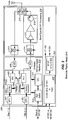
- Figures 2 and 3 depict a low power RRU and high power RRU.
- the RRUs depicted in Figures 2 and 3 can be extended to a multi-band and multi-channel configuration.
- Multi-band implies more than two frequency bands and multichannel implies more than one output to an antenna system.
- Various embodiments of the invention are disclosed.
- An embodiment of the present invention utilizes a RRU Access Module.
- the objective of the access module is to de-multiplex and multiplex high speed data to achieve aggregate data rates sufficient for operation of a plurality of RRU Band Modules which are geographically distributed.
- An alternative embodiment of the present invention utilizes the physical separation of the RRU Band Modules from the RRU Access Module using an optical fiber cable, Ethernet cables, RF cable and any other form of connection between the modules.
- a Remote Radio Unit comprised of one or more RRU Band Modules may be collocated with the antenna or antennas.
- the RRU Access Module can also supply DC power on the interconnection cabling.
- control and measurement algorithms are implemented to permit improved network deployment, network management, and optimization.
- Applications of the present invention are suitable to be employed with all wireless base-stations, remote radio heads, distributed base stations, distributed antenna systems, access points, repeaters, distributed repeaters, optical repeaters, digital repeaters, mobile equipment and wireless terminals, portable wireless devices, and other wireless communication systems such as microwave and satellite communications.
- the present invention is also field upgradable through a link such as an Ethernet connection to a remote computing center.
- the present invention is a novel Distributed Antenna System that utilizes a high speed Remote Radio Head Unit Access Module interconnected with Remote Radio Head Unit Band Module.
- Fiber 1 is a high speed fiber cable that transports data between the BTS and the Remote Radio Head Unit.
- Fiber 2 is used to daisy chain other remote radio head units which are thereby interconnected to the BTS or DAU.
- the software-defined digital platform 216 performs baseband signal processing, typically in an FPGA or equivalent.
- Building block 203 is a Serializer/Deserializer. The deserializer portion extracts the serial input bit stream from the optical fiber 201 and converts it into a parallel bit stream. The serializer portion performs the inverse operation for sending data from the Remote Radio Head Unit to the BTS.
- the two distinct bit streams communicate with the BTS using different optical wavelengths over one fiber, although multiple fibers can be used in alternative arrangements.
- the deframer 204 deciphers the structure of the incoming bit stream and sends the deframed data to the Crest Factor Reduction Algorithm 209.
- the Crest Factor Reduction block 209 reduces the Peak-to-Average Ratio of the incoming signal so as to improve the Power amplifier DC-to-RF conversion efficiency.
- the waveform is then presented to the Digital Predistorter block 208.
- the digital predistorter compensates for the nonlinearities of the Power Amplifier 221 in an adaptive feedback loop.
- Digital Upconverter 210 filters and digitally translates the deframed signal to an IF frequency.
- the Framer 204 takes the data from the two digital downconverters 206, 207 and packs it into a Frame for transmission to the BTS over the optical fiber 201.
- Elements 211 and 212 are Analog to Digital converters that are used to translate the two analog receive signals into digital signals.
- the receiver comprises a diversity branch which contains a downconverter 217 and a Band Pass Filter 223.
- the main branch has a receiver path comprised of a duplexer 224 and a downconverter 218.
- one or both downconverters 217 and 218 can have an integral uplink low-noise amplifier.
- the power amplifier has an output coupler for extracting a replica of the output signal in the feedback path.
- the feedback signal is frequency-translated by downconverter 219 to either an IF frequency or baseband and presented to an Analog to Digital converter 213. This feedback signal is used in an adaptive loop for performing Digital Predistortion to compensate for any nonlinearities created by the power amplifier.
- the Ethernet cable is used to locally communicate with the Remote Radio Head Unit.
- Switch 226 is used to allow easy access to either the FPGA or the CPU.
- DC power converters 228 and 229 are used to obtain the desired DC voltages for the Remote Radio Head Unit. Either an external voltage can be connected directly into the RRU or the DC power may be supplied through the Ethernet cable.
- an alternative embodiment provides multiple optical fiber connections to support a modified "hybrid star" configuration for appropriate applications which dictate this particular optical transport network configuration.
- Figure 3 depicts a remote radio head unit.
- this architecture offers benefits when the RF output power is relatively low.
- digital predistortion and crest factor reduction are not employed as was the case in Figure 2 .
- a diversity receive branch can be added along with an additional transmitter path for development of a Multiple Input Multiple Output (MIMO) Remote Radio Head Unit.
- MIMO Multiple Input Multiple Output
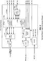
- the Remote Radio Head Unit high level system is shown in Figure 4 . It comprises a Remote Radio Head Unit Access Module 400 which communicates directly with the BTS or DAU.
- the function of the Remote Radio Head Unit Access Module 400 is to route the high speed data (at any desired speed, e.g., such as 10 Gbps as illustrated in Fig. 4 ) (the "Data Speed) to the multiple Remote Radio Head Unit Band Modules and allows for local communications with them via Ethernet.
- a backplane 401 is used to interconnect the Remote Radio Head Unit Access Module 400 with the various Remote Radio Head Unit Band Modules 402,403,404,405 at any speed lower than the Data Speed (e.g., less than or equal to 3Gbps as illustrated in Fig. 4 ).
- the output ports of the Remote Radio Head Unit Band Modules are combined and sent to an antenna for transmission.
- An alternative embodiment is described as follows. Although the description of instant embodiment is directed to applications for up to four Remote Radio Head Unit Band Modules, an alternative embodiment involves feeding a much larger quantity of Remote Radio Head Unit Band Modules with signals of various bandwidths at various frequency bands covering multiple octaves of frequency range, to support a wide range of applications including location-based services, mobile internet, public safety communications, private enterprise telecommunications and broadband, and other wireless applications. The system can in theory support an infinite quantity of RRUs. Also, the Remote Radio Head Unit Band Modules may be set up remotely to have RF power values selected based on the specific desired applications as well as location-specific radio signal propagation factors.
- a further alternative embodiment leverages the flexibility of the architecture shown in Figure 4 to provide a capability known as Flexible Simulcast.
- Flexible Simulcast the amount of radio resources (such as RF carriers, CDMA codes or TDMA time slots) assigned to a particular RRU or group of RRUs by each RRU Access Module can be set via software control to meet desired capacity and throughput objectives or wireless subscriber needs.
- the detailed topology of the Remote Radio Head Unit Access Module is shown in Figure 5 . It comprises a Small form Factor Pluggable optic transceiver (SFP) 500 which operates on two distinct wavelengths, one for communicating from the BTS to the Remote Radio Head Unit Access Module and the other for communicating in the opposite direction.
- the SFP contains a Laser Diode for converting the electronic signal to an optical signal and an Optical detector for converting the optical signal into an electronic signal.
- a multiplexer/demultiplexer 501 converts the high speed data to multiple lower speed data paths for delivery to a FPGA 502. The multiplexer/demultiplexer 501 performs the opposite function when data is being sent back to the BTS or DAU.
- the framer/deframer 503 routes the data to the appropriate Remote Radio Head Unit Band Modules.
- An additional multiplexer/demultiplexer 506 allows for further expansion of lower speed Remote Radio Head Units.
- the number of Remote Radio Head units is only limited by the capability of the FPGA.
- Local communication with the Remote Radio Head Unit's Access Module's FPGA or the individual Remote Radio Head Unit Band Modules is via an Ethernet connection 508.
- the alternative embodiment is one where the digital optical signals fed to the Remote Radio Head Unit Access Module may be generated by an RF-to-Digital interface which receives RF signals by means of one or more antennas directed to one or more base stations located at some distance from the Remote Radio Head Unit Access Module.
- a further alternative embodiment is one where the digital signals fed to the Remote Radio Head Unit Access Module may be generated in a combination of ways; some may be generated by an RF-to-Digital interface and some may be generated by a BTS or DAU. Some neutral host applications gain an advantage with regard to cost-effectiveness from employing this further alternative embodiment.
- the optical signals fed to the Remote Radio Head Unit Access Module described in the preferred and alternative embodiments are digital, the optical signals are not limited to digital, and can be analog or a combination of analog and digital.
- a further alternative embodiment employs transport on one or multiple optical wavelengths fed to the Remote Radio Head Unit Access Module.
- the Remote Radio Head Unit Band Module is shown in Figure 6 . It comprises a Software Defined Digital (SDD) section 610 and an RF section 622.
- SDD Software Defined Digital
- An alternative embodiment employs a Remote Antenna Unit comprising a broadband antenna with RRU Band Module Combiner and multiple plug-in module slots, into which multiple RRU Band Modules intended for operation in different frequency bands are inserted.
- this embodiment employs RRU Band Modules which each have a physically small form factor.
- a suitably small form factor for the RRU Band Module is the PCMCIA module format.
- a further alternative embodiment employs RRU Band Modules where each has an integral antenna, and the embodiment does not require a common antenna shared by multiple RRU Band Modules.
- the Neutral Host Distributed Antenna System of the present invention enables the use of remote radio heads for multi-operator multi-band configurations, which subsequently saves hardware resources and reduces costs.
- the NHDAS system is also reconfigurable and remotely field-programmable since the algorithms can be adjusted like software in the digital processor at any time.
- the NHDAS system is flexible with regard to being able to support various modulation schemes such as QPSK, QAM, OFDM, etc. in CDMA, TD-SCDMA, GSM, WCDMA, CDMA2000, LTE and wireless LAN systems. This means that the NHDAS system is capable of supporting multi-modulation schemes, multi-bands and multi-operators.
Landscapes
- Engineering & Computer Science (AREA)
- Computer Networks & Wireless Communication (AREA)
- Signal Processing (AREA)
- Physics & Mathematics (AREA)
- Electromagnetism (AREA)
- Mobile Radio Communication Systems (AREA)
Applications Claiming Priority (12)
| Application Number | Priority Date | Filing Date | Title |
|---|---|---|---|
| US37459310P | 2010-08-17 | 2010-08-17 | |
| US38283610P | 2010-09-14 | 2010-09-14 | |
| US12/928,933 US8730786B2 (en) | 2009-12-21 | 2010-12-21 | Remote radio head unit system with wideband power amplifier and method |
| US12/928,931 US8804870B2 (en) | 2009-12-21 | 2010-12-21 | Modulation agnostic digital hybrid mode power amplifier system and method |
| US12/928,934 US8351877B2 (en) | 2010-12-21 | 2010-12-21 | Multi-band wideband power amplifier digital predistorition system and method |
| US12/928,943 US8542768B2 (en) | 2009-12-21 | 2010-12-21 | High efficiency, remotely reconfigurable remote radio head unit system and method for wireless communications |
| US201161439940P | 2011-02-07 | 2011-02-07 | |
| EP11818694.9A EP2606435A4 (de) | 2010-08-17 | 2011-08-16 | Neutrale host-architektur für ein verteiltes antennensystem |
| US13/211,247 US8737300B2 (en) | 2006-12-26 | 2011-08-16 | Daisy-chained ring of remote units for a distributed antenna system |
| PCT/US2011/047995 WO2012024343A1 (en) | 2010-08-17 | 2011-08-16 | Neutral host architecture for a distributed antenna system |
| US13/211,243 US8682338B2 (en) | 2010-09-14 | 2011-08-16 | Remotely reconfigurable distributed antenna system and methods |
| US13/211,236 US8848766B2 (en) | 2010-08-17 | 2011-08-16 | Neutral host architecture for a distributed antenna system |
Related Parent Applications (1)
| Application Number | Title | Priority Date | Filing Date |
|---|---|---|---|
| EP11818694.9A Division EP2606435A4 (de) | 2010-08-17 | 2011-08-16 | Neutrale host-architektur für ein verteiltes antennensystem |
Publications (1)
| Publication Number | Publication Date |
|---|---|
| EP3681111A1 true EP3681111A1 (de) | 2020-07-15 |
Family
ID=45605420
Family Applications (3)
| Application Number | Title | Priority Date | Filing Date |
|---|---|---|---|
| EP11818697.2A Active EP2606576B1 (de) | 2010-08-17 | 2011-08-16 | Daisy-chain-ring aus entfernten einheiten für ein verteiltes antennensystem |
| EP11818694.9A Withdrawn EP2606435A4 (de) | 2010-08-17 | 2011-08-16 | Neutrale host-architektur für ein verteiltes antennensystem |
| EP20160422.0A Withdrawn EP3681111A1 (de) | 2010-08-17 | 2011-08-16 | Aus der ferne rekonfigurierbare fernfunkkopfeinheit |
Family Applications Before (2)
| Application Number | Title | Priority Date | Filing Date |
|---|---|---|---|
| EP11818697.2A Active EP2606576B1 (de) | 2010-08-17 | 2011-08-16 | Daisy-chain-ring aus entfernten einheiten für ein verteiltes antennensystem |
| EP11818694.9A Withdrawn EP2606435A4 (de) | 2010-08-17 | 2011-08-16 | Neutrale host-architektur für ein verteiltes antennensystem |
Country Status (2)
| Country | Link |
|---|---|
| EP (3) | EP2606576B1 (de) |
| WO (2) | WO2012024349A1 (de) |
Families Citing this family (25)
| Publication number | Priority date | Publication date | Assignee | Title |
|---|---|---|---|---|
| US8811917B2 (en) | 2002-05-01 | 2014-08-19 | Dali Systems Co. Ltd. | Digital hybrid mode power amplifier system |
| US8380143B2 (en) | 2002-05-01 | 2013-02-19 | Dali Systems Co. Ltd | Power amplifier time-delay invariant predistortion methods and apparatus |
| KR20100014339A (ko) | 2006-12-26 | 2010-02-10 | 달리 시스템즈 씨오. 엘티디. | 다중 채널 광대역 통신 시스템에서의 기저 대역 전치 왜곡 선형화를 위한 방법 및 시스템 |
| US8346091B2 (en) | 2009-04-29 | 2013-01-01 | Andrew Llc | Distributed antenna system for wireless network systems |
| US8848766B2 (en) | 2010-08-17 | 2014-09-30 | Dali Systems Co. Ltd. | Neutral host architecture for a distributed antenna system |
| KR102136940B1 (ko) | 2010-09-14 | 2020-07-23 | 달리 시스템즈 씨오. 엘티디. | 원격으로 재구성가능한 분산 안테나 시스템 및 방법 |
| EP2640072A1 (de) * | 2012-03-13 | 2013-09-18 | Alcatel Lucent International | System und Verfahren zur Übertragung eines Videosignals |
| US10506454B2 (en) * | 2012-07-31 | 2019-12-10 | Dali Systems Co., Ltd. | Optimization of traffic load in a distributed antenna system |
| EP2789107B1 (de) | 2012-08-09 | 2017-02-15 | Axell Wireless Ltd. | Auf digitale kapazität zentriertes verteiltes antennensystem |
| CN102917370B (zh) * | 2012-10-19 | 2015-02-18 | 京信通信系统(中国)有限公司 | 确定远端机对应的近端机的方法、装置、系统以及远端机 |
| CN104782093B (zh) * | 2012-10-31 | 2018-02-27 | 康普技术有限责任公司 | 远程通信分配系统中的数字基带传输 |
| US9955361B2 (en) | 2013-02-26 | 2018-04-24 | Dali Systems Co., Ltd. | Method and system for WI-FI data transmission |
| KR102116539B1 (ko) | 2013-09-06 | 2020-05-29 | 주식회사 케이엠더블유 | 원격 무선 장비 |
| JP6315938B2 (ja) * | 2013-10-15 | 2018-04-25 | 三菱電機株式会社 | 光伝送装置 |
| US9847816B2 (en) | 2013-12-19 | 2017-12-19 | Dali Systems Co. Ltd. | Digital transport of data over distributed antenna network |
| US10284296B2 (en) | 2014-02-13 | 2019-05-07 | Dali Systems Co. Ltd. | System and method for performance optimization in and through a distributed antenna system |
| CA3017856A1 (en) | 2014-09-23 | 2016-03-31 | Axell Wireless Ltd. | Automatic mapping and handling pim and other uplink interferences in digital distributed antenna systems |
| CA2971853A1 (en) | 2014-12-23 | 2016-06-30 | Abraham Hasarchi | Harmonizing noise aggregation and noise management in distributed antenna system |
| KR101793887B1 (ko) | 2015-08-03 | 2017-11-06 | (주)에이디알에프코리아 | Das 인터페이스 장치 |
| CN105656589B (zh) * | 2015-12-30 | 2018-05-22 | 三维通信股份有限公司 | 一种das系统中6.5g/10g光纤速率的自适应方法 |
| KR101791636B1 (ko) | 2016-03-28 | 2017-10-30 | 주식회사 쏠리드 | 기지국 신호 정합 장치, 이를 포함하는 기지국 인터페이스 유닛 및 분산 안테나 시스템 |
| US10644798B2 (en) | 2016-05-12 | 2020-05-05 | Dali Systems Co. Ltd. | Redundancy in a public safety Distributed Antenna System |
| KR102054180B1 (ko) | 2016-11-29 | 2020-01-22 | 한국전자통신연구원 | 대용량의 데이터 트래픽을 지원하는 분산형 안테나 시스템을 위한 리모트 라디오 헤드 장치 및 호스트 장치 |
| KR102478166B1 (ko) | 2016-11-29 | 2022-12-16 | 한국전자통신연구원 | 대용량의 데이터 트래픽을 지원하는 분산형 안테나 시스템을 위한 호스트 장치 및 라디오 장치 |
| KR101877004B1 (ko) * | 2017-09-29 | 2018-07-10 | 주식회사 쏠리드 | 오픈플로우 기반의 분산 안테나 시스템 |
Citations (6)
| Publication number | Priority date | Publication date | Assignee | Title |
|---|---|---|---|---|
| US5880863A (en) * | 1996-02-13 | 1999-03-09 | Gte Laboratories Incorporated | Reconfigurable ring system for the transport of RF signals over optical fibers |
| US20050041968A1 (en) * | 2003-08-21 | 2005-02-24 | Fujitsu Limited | Optical transmission system |
| US20070274279A1 (en) * | 2005-12-19 | 2007-11-29 | Wood Steven A | Distributed antenna system employing digital forward deployment of wireless transmit/receive locations |
| US20090029664A1 (en) * | 2007-07-27 | 2009-01-29 | Optichron, Inc. | Crest factor reduction |
| US20100177760A1 (en) * | 2009-01-13 | 2010-07-15 | Adc Telecommunications, Inc. | Systems and methods for improved digital rf transport in distributed antenna systems |
| US10850208B2 (en) | 2018-03-29 | 2020-12-01 | T. Dashon Howard | Systems and methods for transcendental lighting applications |
Family Cites Families (12)
| Publication number | Priority date | Publication date | Assignee | Title |
|---|---|---|---|---|
| US7016332B2 (en) * | 2000-12-05 | 2006-03-21 | Science Applications International Corporation | Method and system for a remote downlink transmitter for increasing the capacity of a multiple access interference limited spread-spectrum wireless network |
| US7127175B2 (en) * | 2001-06-08 | 2006-10-24 | Nextg Networks | Method and apparatus for multiplexing in a wireless communication infrastructure |
| US6882833B2 (en) * | 2002-02-22 | 2005-04-19 | Blue7 Communications | Transferring data in a wireless communication system |
| WO2004059934A1 (en) * | 2002-12-24 | 2004-07-15 | Pirelli & C. S.P.A. | Radio base station receiver having digital filtering and reduced sampling frequency |
| SE0302596D0 (sv) * | 2003-09-30 | 2003-09-30 | Ericsson Telefon Ab L M | Improvments in or relating to base stations |
| EP1750376B1 (de) * | 2004-06-14 | 2015-10-21 | Panasonic Intellectual Property Management Co., Ltd. | Funkkommunikationsgerät |
| CN100426897C (zh) * | 2005-01-12 | 2008-10-15 | 华为技术有限公司 | 分体式基站系统及其组网方法和基带单元 |
| US7813451B2 (en) * | 2006-01-11 | 2010-10-12 | Mobileaccess Networks Ltd. | Apparatus and method for frequency shifting of a wireless signal and systems using frequency shifting |
| US7599711B2 (en) * | 2006-04-12 | 2009-10-06 | Adc Telecommunications, Inc. | Systems and methods for analog transport of RF voice/data communications |
| JP4981494B2 (ja) * | 2006-05-30 | 2012-07-18 | 株式会社日立国際電気 | 無線通信システム及び張り出し局装置 |
| US20080045254A1 (en) * | 2006-08-15 | 2008-02-21 | Motorola, Inc. | Method and Apparatus for Maximizing Resource Utilization of Base Stations in a Communication Network |
| JP5591106B2 (ja) * | 2007-04-23 | 2014-09-17 | ダリ システムズ カンパニー リミテッド | デジタルハイブリッドモード電力増幅器システム |
-
2011
- 2011-08-16 EP EP11818697.2A patent/EP2606576B1/de active Active
- 2011-08-16 EP EP11818694.9A patent/EP2606435A4/de not_active Withdrawn
- 2011-08-16 WO PCT/US2011/048004 patent/WO2012024349A1/en not_active Ceased
- 2011-08-16 EP EP20160422.0A patent/EP3681111A1/de not_active Withdrawn
- 2011-08-16 WO PCT/US2011/047995 patent/WO2012024343A1/en not_active Ceased
Patent Citations (6)
| Publication number | Priority date | Publication date | Assignee | Title |
|---|---|---|---|---|
| US5880863A (en) * | 1996-02-13 | 1999-03-09 | Gte Laboratories Incorporated | Reconfigurable ring system for the transport of RF signals over optical fibers |
| US20050041968A1 (en) * | 2003-08-21 | 2005-02-24 | Fujitsu Limited | Optical transmission system |
| US20070274279A1 (en) * | 2005-12-19 | 2007-11-29 | Wood Steven A | Distributed antenna system employing digital forward deployment of wireless transmit/receive locations |
| US20090029664A1 (en) * | 2007-07-27 | 2009-01-29 | Optichron, Inc. | Crest factor reduction |
| US20100177760A1 (en) * | 2009-01-13 | 2010-07-15 | Adc Telecommunications, Inc. | Systems and methods for improved digital rf transport in distributed antenna systems |
| US10850208B2 (en) | 2018-03-29 | 2020-12-01 | T. Dashon Howard | Systems and methods for transcendental lighting applications |
Also Published As
| Publication number | Publication date |
|---|---|
| EP2606435A4 (de) | 2017-05-10 |
| EP2606576A4 (de) | 2017-09-20 |
| EP2606435A1 (de) | 2013-06-26 |
| WO2012024343A1 (en) | 2012-02-23 |
| EP2606576B1 (de) | 2024-01-17 |
| WO2012024349A1 (en) | 2012-02-23 |
| EP2606576A1 (de) | 2013-06-26 |
Similar Documents
| Publication | Publication Date | Title |
|---|---|---|
| US20240292380A1 (en) | Neutral host architecture for a distributed antenna system | |
| KR101662879B1 (ko) | 분산 안테나 시스템을 위한 뉴트럴 호스트 아키텍처 | |
| WO2012024343A1 (en) | Neutral host architecture for a distributed antenna system | |
| US20240195456A1 (en) | Network switch for a distributed antenna network | |
| EP3462807B1 (de) | Modulare drahtloskommunikationsplattform | |
| EP2749123B1 (de) | Software-konfigurierbares verteiltes antennensystem und verfahren zur unterdrückung von uplink-geräuschen dafür | |
| EP4138310B1 (de) | Entwickeltes verteiltes antennensystem | |
| HK40023242A (en) | Remotely reconfigurable remote radio head unit | |
| HK1250427B (zh) | 远程地可重新配置的远程无线电头单元 | |
| HK1226892A1 (en) | Network switch for a distributed antenna network |
Legal Events
| Date | Code | Title | Description |
|---|---|---|---|
| PUAI | Public reference made under article 153(3) epc to a published international application that has entered the european phase |
Free format text: ORIGINAL CODE: 0009012 |
|
| STAA | Information on the status of an ep patent application or granted ep patent |
Free format text: STATUS: THE APPLICATION HAS BEEN PUBLISHED |
|
| AC | Divisional application: reference to earlier application |
Ref document number: 2606435 Country of ref document: EP Kind code of ref document: P |
|
| AK | Designated contracting states |
Kind code of ref document: A1 Designated state(s): AL AT BE BG CH CY CZ DE DK EE ES FI FR GB GR HR HU IE IS IT LI LT LU LV MC MK MT NL NO PL PT RO RS SE SI SK SM TR |
|
| REG | Reference to a national code |
Ref country code: HK Ref legal event code: DE Ref document number: 40023242 Country of ref document: HK |
|
| STAA | Information on the status of an ep patent application or granted ep patent |
Free format text: STATUS: REQUEST FOR EXAMINATION WAS MADE |
|
| 17P | Request for examination filed |
Effective date: 20210111 |
|
| RBV | Designated contracting states (corrected) |
Designated state(s): AL AT BE BG CH CY CZ DE DK EE ES FI FR GB GR HR HU IE IS IT LI LT LU LV MC MK MT NL NO PL PT RO RS SE SI SK SM TR |
|
| STAA | Information on the status of an ep patent application or granted ep patent |
Free format text: STATUS: EXAMINATION IS IN PROGRESS |
|
| 17Q | First examination report despatched |
Effective date: 20210512 |
|
| P01 | Opt-out of the competence of the unified patent court (upc) registered |
Effective date: 20230424 |
|
| STAA | Information on the status of an ep patent application or granted ep patent |
Free format text: STATUS: THE APPLICATION IS DEEMED TO BE WITHDRAWN |
|
| 18D | Application deemed to be withdrawn |
Effective date: 20230905 |