EP3681210A1 - Procédé de commande de puissance, procédé de réception, procédé d'attribution de puissance, équipement utilisateur et dispositif de réseau - Google Patents
Procédé de commande de puissance, procédé de réception, procédé d'attribution de puissance, équipement utilisateur et dispositif de réseau Download PDFInfo
- Publication number
- EP3681210A1 EP3681210A1 EP20160684.5A EP20160684A EP3681210A1 EP 3681210 A1 EP3681210 A1 EP 3681210A1 EP 20160684 A EP20160684 A EP 20160684A EP 3681210 A1 EP3681210 A1 EP 3681210A1
- Authority
- EP
- European Patent Office
- Prior art keywords
- bwp
- target
- power
- reference signal
- present disclosure
- Prior art date
- Legal status (The legal status is an assumption and is not a legal conclusion. Google has not performed a legal analysis and makes no representation as to the accuracy of the status listed.)
- Granted
Links
Images





Classifications
-
- H—ELECTRICITY
- H04—ELECTRIC COMMUNICATION TECHNIQUE
- H04W—WIRELESS COMMUNICATION NETWORKS
- H04W52/00—Power management, e.g. Transmission Power Control [TPC] or power classes
- H04W52/04—Transmission power control [TPC]
- H04W52/30—Transmission power control [TPC] using constraints in the total amount of available transmission power
- H04W52/32—TPC of broadcast or control channels
- H04W52/325—Power control of control or pilot channels
-
- H—ELECTRICITY
- H04—ELECTRIC COMMUNICATION TECHNIQUE
- H04W—WIRELESS COMMUNICATION NETWORKS
- H04W52/00—Power management, e.g. Transmission Power Control [TPC] or power classes
- H04W52/04—Transmission power control [TPC]
- H04W52/06—TPC algorithms
- H04W52/14—Separate analysis of uplink or downlink
-
- H—ELECTRICITY
- H04—ELECTRIC COMMUNICATION TECHNIQUE
- H04W—WIRELESS COMMUNICATION NETWORKS
- H04W52/00—Power management, e.g. Transmission Power Control [TPC] or power classes
- H04W52/04—Transmission power control [TPC]
- H04W52/06—TPC algorithms
- H04W52/14—Separate analysis of uplink or downlink
- H04W52/143—Downlink power control
-
- H—ELECTRICITY
- H04—ELECTRIC COMMUNICATION TECHNIQUE
- H04W—WIRELESS COMMUNICATION NETWORKS
- H04W52/00—Power management, e.g. Transmission Power Control [TPC] or power classes
- H04W52/04—Transmission power control [TPC]
- H04W52/06—TPC algorithms
- H04W52/14—Separate analysis of uplink or downlink
- H04W52/146—Uplink power control
-
- H—ELECTRICITY
- H04—ELECTRIC COMMUNICATION TECHNIQUE
- H04W—WIRELESS COMMUNICATION NETWORKS
- H04W52/00—Power management, e.g. Transmission Power Control [TPC] or power classes
- H04W52/04—Transmission power control [TPC]
- H04W52/18—TPC being performed according to specific parameters
- H04W52/24—TPC being performed according to specific parameters using SIR [Signal to Interference Ratio] or other wireless path parameters
-
- H—ELECTRICITY
- H04—ELECTRIC COMMUNICATION TECHNIQUE
- H04W—WIRELESS COMMUNICATION NETWORKS
- H04W52/00—Power management, e.g. Transmission Power Control [TPC] or power classes
- H04W52/04—Transmission power control [TPC]
- H04W52/18—TPC being performed according to specific parameters
- H04W52/24—TPC being performed according to specific parameters using SIR [Signal to Interference Ratio] or other wireless path parameters
- H04W52/242—TPC being performed according to specific parameters using SIR [Signal to Interference Ratio] or other wireless path parameters taking into account path loss
-
- H—ELECTRICITY
- H04—ELECTRIC COMMUNICATION TECHNIQUE
- H04W—WIRELESS COMMUNICATION NETWORKS
- H04W52/00—Power management, e.g. Transmission Power Control [TPC] or power classes
- H04W52/04—Transmission power control [TPC]
- H04W52/18—TPC being performed according to specific parameters
- H04W52/24—TPC being performed according to specific parameters using SIR [Signal to Interference Ratio] or other wireless path parameters
- H04W52/248—TPC being performed according to specific parameters using SIR [Signal to Interference Ratio] or other wireless path parameters where transmission power control commands are generated based on a path parameter
-
- H—ELECTRICITY
- H04—ELECTRIC COMMUNICATION TECHNIQUE
- H04W—WIRELESS COMMUNICATION NETWORKS
- H04W52/00—Power management, e.g. Transmission Power Control [TPC] or power classes
- H04W52/04—Transmission power control [TPC]
- H04W52/30—Transmission power control [TPC] using constraints in the total amount of available transmission power
- H04W52/34—TPC management, i.e. sharing limited amount of power among users or channels or data types, e.g. cell loading
- H04W52/346—TPC management, i.e. sharing limited amount of power among users or channels or data types, e.g. cell loading distributing total power among users or channels
-
- H—ELECTRICITY
- H04—ELECTRIC COMMUNICATION TECHNIQUE
- H04W—WIRELESS COMMUNICATION NETWORKS
- H04W52/00—Power management, e.g. Transmission Power Control [TPC] or power classes
- H04W52/04—Transmission power control [TPC]
- H04W52/30—Transmission power control [TPC] using constraints in the total amount of available transmission power
- H04W52/36—Transmission power control [TPC] using constraints in the total amount of available transmission power with a discrete range or set of values, e.g. step size, ramping or offsets
- H04W52/365—Power headroom reporting
-
- H—ELECTRICITY
- H04—ELECTRIC COMMUNICATION TECHNIQUE
- H04W—WIRELESS COMMUNICATION NETWORKS
- H04W52/00—Power management, e.g. Transmission Power Control [TPC] or power classes
- H04W52/04—Transmission power control [TPC]
- H04W52/30—Transmission power control [TPC] using constraints in the total amount of available transmission power
- H04W52/36—Transmission power control [TPC] using constraints in the total amount of available transmission power with a discrete range or set of values, e.g. step size, ramping or offsets
- H04W52/367—Power values between minimum and maximum limits, e.g. dynamic range
-
- H—ELECTRICITY
- H04—ELECTRIC COMMUNICATION TECHNIQUE
- H04W—WIRELESS COMMUNICATION NETWORKS
- H04W72/00—Local resource management
- H04W72/04—Wireless resource allocation
- H04W72/044—Wireless resource allocation based on the type of the allocated resource
- H04W72/0473—Wireless resource allocation based on the type of the allocated resource the resource being transmission power
Definitions
- the present disclosure relates to the field of communication technology, in particular to a power control method, a reception method, a power allocation method, a User Equipment (UE) and a network device.
- a power control method a reception method, a power allocation method, a User Equipment (UE) and a network device.
- UE User Equipment
- a 5 th -Generation (5G) mobile communication system may support a system bandwidth of 100MHz or 400MHz, which is far greater than a maximum system bandwidth (i.e., 20MHz) supported by a Long Term Evolution (LTE) system, so as to support a larger system capacity and a larger user throughput.
- 5G 5 th -Generation
- LTE Long Term Evolution
- BWP Bandwidth Part
- the system bandwidth may be divided into one or more BWPs, and one or more BWPs may be configured for each UE.
- usually power management is performed on the basis of carriers, and there is currently no scheme for the power management over the BWPs.
- the present disclosure provides in some embodiments a power control method, including performing transmission power control over uplink transmission on a first target BWP in accordance with one or more target uplink power control parameters corresponding to the first target BWP.
- the present disclosure provides in some embodiments a reception method, including receiving uplink transmission on a first target BWP in accordance with one or more target uplink power control parameters corresponding to the first target BWP.
- the present disclosure provides in some embodiments a power allocation method, including allocating transmission power with respect to downlink transmission on a second target BWP in accordance with one or more target downlink power adjustment parameters corresponding to the second target BWP.
- the present disclosure provides in some embodiments a reception method, including receiving downlink transmission on a second target BWP in accordance with one or more target downlink power adjustment parameters corresponding to the second target BWP.
- the present disclosure provides in some embodiments a UE, including a first control module configured to perform transmission power control over uplink transmission on a first target BWP in accordance with one or more target uplink power control parameters corresponding to the first target BWP.
- the present disclosure provides in some embodiments a network device, including a third reception module configured to receive uplink transmission on a first target BWP in accordance with one or more target uplink power control parameters corresponding to the first target BWP.
- the present disclosure provides in some embodiments a network device, including an allocation module configured to allocate transmission power with respect to downlink transmission on a second target BWP in accordance with one or more target downlink power adjustment parameters corresponding to the second target BWP.
- the present disclosure provides in some embodiments a UE, including a fifth reception module configured to receive downlink transmission on a second target BWP in accordance with one or more target downlink power adjustment parameters corresponding to the second target BWP.
- the present disclosure provides in some embodiments a UE, including a memory, a processor, and a computer program stored in the memory and executed by the processor.
- the processor is configured to execute the computer program so as to implement the above-mentioned power control method or the above-mentioned reception method.
- the present disclosure provides in some embodiments a network device, including a memory, a processor, and a computer program stored in the memory and executed by the processor.
- the processor is configured to execute the computer program so as to implement the above-mentioned power control method or the above-mentioned reception method.
- the present disclosure provides in some embodiments a computer-readable storage medium storing therein a computer program.
- the computer program is executed by a processor so as to implement the above-mentioned power control method or the above-mentioned reception method.
- the present disclosure provides in some embodiments a computer-readable storage medium storing therein a computer program.
- the computer program is executed by a processor so as to implement the above-mentioned power control method or the above-mentioned reception method.
- uplink power control is used to control transmission power of different uplink physical channels, e.g., the uplink power control may include Physical Uplink Shared Channel (PUSCH) power control, Physical Uplink Control Channel (PUCCH) power control, Sounding Reference Signal (SRS) power control, etc.
- PUSCH Physical Uplink Shared Channel
- PUCCH Physical Uplink Control Channel
- SRS Sounding Reference Signal
- a Single Carrier Frequency Division Multiple Access (SC-FDMA) waveform is adopted for the uplink transmission in the LTE system, and an open-close plus closed-loop mode is adopted for the uplink power control.
- downlink power allocation is used to determine transmission power on each Resource Element (RE) for downlink transmission.
- RE Resource Element
- the LTE system supports user-based low-speed power allocation where the setting of the following power parameters is involved.
- EPRE Energy Per Resource Element
- CRS Cell Reference Signal
- CSI-RS Channel State Information-Reference Signal
- EPRE of a data resource it represents transmission power on each RE of the data resource, and it is UE-specific.
- a network side e.g., a base station
- RRC Radio Resource Control
- one or more BWPs may be configured for one UE.
- the BWPs may have a same configuration parameter or different configuration parameters (i.e., Numerologies).
- adjacent serving cells may transmit uplink or downlink services using different BWPs at a same time point, resulting in difference interferences between the adjacent serving cells on different BWPs.
- one serving cell may transmit or receive different BWPs using different transmission points.
- a same power control mode as the LTE system i.e., when power control is performed on each carrier, there may exist a difference between the BWPs in terms of the transmission performance, and thereby the system performance may be reduced.
- inaccurate power control may lead to unnecessary power transmission, resulting in an increase in the power consumption as well as an intra-system interference.
- power management may be performed on each BWP, i.e., one or more power management parameters (e.g., an uplink power control parameter and a downlink power adjustment parameter) for each BWP may be configured and processed, so as to improve the system performance.
- one or more power management parameters e.g., an uplink power control parameter and a downlink power adjustment parameter
- FIG. 1 shows an available network according to some embodiments of the present disclosure.
- the network includes a UE 10 and a network device 20.
- the UE 10 may communicate with the network device 20 via the network.
- the UE 10 may be a mobile phone, a tablet personal computer, a laptop computer, a Personal Digital Assistant (PDA), a Mobile Internet Device (MID) or a wearable device.
- the network device may be an evolved Node B (eNB or eNodeB), a relay, an access point, a base station in a 5G network (gNB), or a wireless network controller at a network side, which will not be particularly defined herein.
- eNB or eNodeB evolved Node B
- gNB 5G network
- wireless network controller at a network side, which will not be particularly defined herein.
- the UE 10 may perform transmission power control over uplink transmission on a first target BWP in accordance with one or more target uplink power control parameters corresponding to the first target BWP.
- the network device 20 may receive the uplink transmission on the first target BWP in accordance with one or more target uplink power control parameters corresponding to the first target BWP. As a result, it is able to standardize the power control with respect to one or more BWPs.
- the network device 20 may allocate transmission power with respect to downlink transmission on a second target BWP in accordance with one or more target downlink power adjustment parameters corresponding to the second target BWP.
- the UE 10 may receive the downlink transmission on the second target BWP in accordance with the one or more target downlink power adjustment parameters corresponding to the second target BWP. As a result, it is able to standardize the power control with respect to one or more BWPs.
- the present disclosure provides in some embodiments a power control method for a UE which, as shown in FIG. 2 , includes Step 201 of performing transmission power control over uplink transmission on a first target BWP in accordance with one or more target uplink power control parameters corresponding to the first target BWP.
- a system bandwidth may be divided into one or more BWPs, and the UE may support one or more BWPs.
- the first target BWP may be any one of the at least two BWPs.
- one or more uplink power control parameters may be configured separately for each BWP, and the UE may control the transmission power for the uplink transmission on each BWP in accordance with the one or more uplink power control parameters for each BWP.
- the one or more target uplink power control parameters may include at least one of maximum transmission power, target received power, a power compensation factor, a path loss reference, a power adjustment value, and a Transmission Power Control (TPC) command word.
- TPC Transmission Power Control
- the maximum transmission power may refer to maximum transmission power P cmax,bwp of the UE on each BWP.
- the maximum transmission power P cmax,bwp of the UE on each BWP may be determined in accordance with a maximum transmission power parameter.
- the maximum transmission power parameter may include, but not limited to, maximum transmission power P EMAX,c and/or Additional Maximum Power Reduction (A-MPR).
- the target received power may include, but not limited to, at least one of a power target value of a PUSCH, i.e., Po_PUSCH, a received power target value of a PUCCH, i.e., Po_PUCCH, a received power target value of an SRS, i.e., Po_SRS (or a received power target offset of the SRS, i.e., Po_SRS_offset), and a received power target value of a preamble, i.e., Po_preamble.
- a power target value of a PUSCH i.e., Po_PUSCH
- a received power target value of a PUCCH i.e., Po_PUCCH
- a received power target value of an SRS i.e., Po_SRS (or a received power target offset of the SRS, i.e., Po_SRS_offset)
- a received power target value of a preamble i.e.
- the power compensation factor may be ⁇ mentioned hereinabove.
- a network side may configure a downlink (DL) path loss reference for each uplink (UL) BWP, e.g., a downlink BWP where a path loss needs to be measured.
- DL downlink
- UL uplink
- the power adjustment value may include a power adjustment value associated with a transmission format, a power adjustment value associated with a PUCCH format, and a power adjustment value associated with a PUCCH antenna mode.
- the power adjustment value associated with the transmission format may be configured for each uplink BWP.
- the power adjustment value associated with the transmission format may include an adjustment value associated with an MCS transmitted via the PUSCH, and/or an adjustment value ⁇ offset PUSCH of Uplink Control Information (UCI) relative to the PUSCH when the UCI is carried in the PUSCH.
- UCI Uplink Control Information
- the power adjustment value associated with the PUCCH format may include ⁇ F_PUCCH ( F ), i.e., relative power offsets for different PUCCH formats.
- the power adjustment value associated with the PUCCH antenna mode may include ⁇ TxD ( F' ), i.e., a power adjustment value of the transmission power for the PUCCH when transmission diversity is adopted relative to the transmission power when no transmission diversity is adopted.
- the network side e.g., the base station
- the network side may transmit a separate TPC command word with respect to each BWP
- the UE may accumulate the TPC commands with respect to each BWP.
- the transmission power control may be performed over the uplink transmission on the first target BWP in accordance with the one or more target uplink power control parameters corresponding to the first target BWP.
- the power control is performed on each carrier, it is able to improve the system performance.
- it is able to reduce the unnecessary power transmission, thereby to reduce the power consumption as well as the intra-system interference.
- the one or more target uplink power control parameters may be predefined in a communication protocol between the UE and the network device, or configured by the network device and transmitted to the UE.
- the power control method may further include receiving one or more uplink power control parameters corresponding to each BWP from the network device.
- the entire bandwidth may consist of one or more BWPs.
- the entire bandwidth includes merely one BWP, the one or more uplink power control parameters corresponding to the BWP may be transmitted.
- the entire bandwidth includes a plurality of BWPs, the one or more uplink power control parameters corresponding to each BWP may be transmitted.
- the network side may configure one or more uplink power control parameters for each BWP, and transmit the one or more uplink power control parameters to the UE, so that the UE may determine the uplink transmission power for each BWP in accordance with the one or more uplink power control parameters corresponding to each BWP.
- the network device may configure the one or more uplink power control parameters for each BWP, so as to flexibly control the one or more uplink power control parameters corresponding to each BWP, e.g., to configure the one or more uplink power control parameters corresponding to each BWP in accordance with a bandwidth of each BWP and the UE capability.
- the network device may configure the one or more uplink power control parameters for each BWP, so as to flexibly control the one or more uplink power control parameters corresponding to each BWP, e.g., to configure the one or more uplink power control parameters corresponding to each BWP in accordance with a bandwidth of each BWP and the UE capability.
- the power control method may further include: with respect to an SC-FDMA mode, calculating an actual power headroom corresponding to the first target BWP in accordance with maximum transmission power corresponding to the first target BWP and actual transmission power of the PUSCH, and transmitting the actual power headroom; or with respect to an Orthogonal Frequency Division Multiple Access (OFDMA) mode, calculating a virtual power headroom in accordance with the maximum transmission power corresponding to the first target BWP and virtual transmission power of the PUSCH, and transmitting the virtual power headroom.
- SC-FDMA SC-FDMA
- OFDMA Orthogonal Frequency Division Multiple Access
- the UE may calculate the actual transmission power corresponding to the first target BWP in accordance with the one or more uplink power control parameters corresponding to the first target BWP, i.e., actual transmission power P pusch,bwp for the PUSCH and actual transmission power P pucch,bwp for the PUCCH on the first target BWP.
- PHR bwp positive, it means that the transmission power of the UE has not reached a maximum value yet, and more bandwidth resources may be allocated for the UE, so as to transmit more data.
- PHR bwp is negative, it means that the transmission power of the UE has reached the maximum value, and the quantity of the bandwidth resources for the UE needs to be reduced, so as to ensure the service quality.
- the actual power headroom corresponding to the first target BWP or the virtual power headroom corresponding to the first target BWP acquired through calculation may be transmitted to the network device, so that the network device may adjust the bandwidth resources for the UE in accordance with the actual power headroom corresponding to the first target BWP or the virtual power headroom corresponding to the first target BWP, thereby to improve the data transmission volume while ensuring the serving quality.
- the power control method may further include: receiving a BWP adjustment command from the network device; and determining the first target BWP in accordance with the BWP adjustment command.
- the network device may transmit the BWP adjustment command to the UE via L1/L2 signaling, so that the UE may adjust the BWP in accordance with the BWP adjustment command, and thereby determine the first target BWP.
- each BWP may have relevant power control parameters.
- the network device dynamically adjusts the BWPs for the UE via the L1/L2 signaling (e.g., when the network device performs dynamic switching among the plurality of pre-configured BWPs)
- the UE may use the power control parameter corresponding to a currently active BWP.
- the BWP may be further adjusted in the following modes.
- Mode 1 a central frequency point of the BWP may remain unchanged, and the BWP bandwidth may be changed; in Mode 2, the central frequency point of the BWP may be changed, and the BWP bandwidth may remain unchanged; and in Mode 3, the central frequency point of the BWP may be changed, and the BWP bandwidth may be changed too.
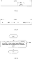
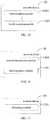
- FIG. 3 through FIG. 5 show several BWP application scenarios respectively.
- the UE may access one BWP of the system bandwidth, as shown in FIG. 3 .
- the BWP for the UE may be adjusted, with the central frequency point of the BWP being unchanged and the BWP bandwidth being changed, as shown in FIG. 4 .
- the UE may access two BWPs (i.e., BWP 1 and BWP 2) of the system bandwidth simultaneously, and the two BWPs may have different numerologies, as shown in FIG. 5 .
- the UE may adjust the BWP in accordance with the BWP adjustment command, so as to conveniently adjust the bandwidth resources for the UE.
- the present disclosure further provides in some embodiments a reception method for a network device which, as shown in FIG. 6 , includes Step 601 of receiving uplink transmission on a first target BWP in accordance with one or more target uplink power control parameters corresponding to the first target BWP.
- the network device may receive the uplink transmission on the first target BWP in accordance with the one or more target uplink power control parameters corresponding to the first target BWP.
- the one or more uplink power control parameters may be separately configured for each BWP, and the network device may receive the uplink transmission on each BWP in accordance with the one or more uplink power control parameters corresponding to each BWP.
- the one or more target uplink power control parameters may include at least one of maximum transmission power, target received power, a power compensation factor, a path loss reference, a power adjustment value, and a TPC command word.
- the maximum transmission power may refer to maximum transmission power P cmax,bwp of the UE on each BWP.
- the maximum transmission power P cmax,bwp of the UE on each BWP may be determined in accordance with a maximum transmission power parameter.
- the maximum transmission power parameter may include, but not limited to, maxim transmission power P EMAX,c and/or A-MPR.
- the target received power may include, but not limited to, at least one of a power target value of a PUSCH, i.e., Po_PUSCH, a received power target value of a PUCCH, i.e., Po_PUCCH, a received power target value of an SRS, i.e., Po_SRS (or a received power target offset of the SRS, i.e., Po_SRS_offset), and a received power target value of a preamble, i.e., Po_preamble.
- a power target value of a PUSCH i.e., Po_PUSCH
- a received power target value of a PUCCH i.e., Po_PUCCH
- a received power target value of an SRS i.e., Po_SRS (or a received power target offset of the SRS, i.e., Po_SRS_offset)
- a received power target value of a preamble i.e.
- the power compensation factor may be ⁇ mentioned hereinabove.
- a network side may configure a downlink (DL) path loss reference for each uplink (UL) BWP, e.g., a downlink BWP where a path loss needs to be measured.
- DL downlink
- UL uplink
- the power adjustment value may include a power adjustment value associated with a transmission format, a power adjustment value associated with a PUCCH format, and a power adjustment value associated with a PUCCH antenna mode.
- the power adjustment value associated with the transmission format may be configured for each uplink BWP.
- the power adjustment value associated with the transmission format may include K S and/or ⁇ offset PUSCH .
- the power adjustment value associated with the PUCCH format may include ⁇ F_PUCCH ( F ).
- the power adjustment value associated with the PUCCH antenna mode may include ⁇ TxD ( F ').
- the network side e.g., the base station
- the network side may transmit a separate TPC command word with respect to each BWP
- the UE may accumulate the TPC commands with respect to each BWP.
- the uplink transmission may be received on the first target BWP in accordance with the one or more target uplink power control parameters corresponding to the first target BWP.
- the power control is performed on each carrier, it is able to improve the system performance.
- it is able to reduce the unnecessary power transmission, thereby to reduce the power consumption as well as the intra-system interference.
- the one or more target uplink power control parameters may be predefined in a communication protocol between the UE and the network device, or configured by the network device and transmitted to the UE.
- the reception method may further include transmitting one or more uplink power control parameters corresponding to each BWP to the UE.
- the network side may configure one or more uplink power control parameters for each BWP, and transmit the one or more uplink power control parameters to the UE, so that the UE may determine the uplink transmission power for each BWP in accordance with the one or more uplink power control parameters corresponding to each BWP.
- the network device may configure the one or more uplink power control parameters for each BWP, so as to flexibly control the one or more uplink power control parameters corresponding to each BWP, e.g., to configure the one or more uplink power control parameters corresponding to each BWP in accordance with a bandwidth of each BWP and the UE capability.
- the network device may configure the one or more uplink power control parameters for each BWP, so as to flexibly control the one or more uplink power control parameters corresponding to each BWP, e.g., to configure the one or more uplink power control parameters corresponding to each BWP in accordance with a bandwidth of each BWP and the UE capability.
- the reception method may further include: with respect to an SC-FDMA mode, receiving an actual power headroom corresponding to the first target BWP calculated in accordance with maximum transmission power corresponding to the first target BWP and actual transmission power of the PUSCH from the UE; or with respect to an OFDMA mode, receiving a virtual power headroom calculated in accordance with the maximum transmission power corresponding to the first target BWP and virtual transmission power of the PUSCH from the UE.
- the UE may calculate the actual transmission power corresponding to the first target BWP in accordance with the one or more uplink power control parameters corresponding to the first target BWP, i.e., actual transmission power P pusch,bwp for the PUSCH and actual transmission power P pucch,bwp for the PUCCH on the first target BWP.
- PHR bwp when PHR bwp is positive, it means that the transmission power of the UE has not reached a maximum value yet, and more bandwidth resources may be allocated for the UE, so as to transmit more data.
- PHR bwp when PHR bwp is negative, it means that the transmission power of the UE has reached the maximum value, and the quantity of the bandwidth resources for the UE needs to be reduced, so as to ensure the service quality.
- the actual power headroom corresponding to the first target BWP or the virtual power headroom corresponding to the first target BWP acquired through calculation may be transmitted to the network device, so that the network device may adjust the bandwidth resources for the UE in accordance with the actual power headroom corresponding to the first target BWP or the virtual power headroom corresponding to the first target BWP, thereby to improve the data transmission volume while ensuring the serving quality.
- the reception method may further include transmitting a BWP adjustment command indicating the first target BWP.
- the network device may transmit the BWP adjustment command to the UE via L1/L2 signaling, so that the UE may adjust the BWP in accordance with the BWP adjustment command, and thereby determine the first target BWP.
- each BWP may be configured with relevant power control parameters.
- the network device dynamically adjusts the BWPs for the UE via the L1/L2 signaling (e.g., when the network device performs dynamic switching among the plurality of pre-configured BWPs)
- the UE may use the power control parameter corresponding to a currently active BWP.
- the network device may transmit the BWP adjustment command indicating the first target BWP to the UE, so that the UE may perform the BWP adjustment in accordance with the BWP adjustment command, so as to conveniently adjust the bandwidth resources for the UE.
- the present disclosure further provides in some embodiments a power allocation method for a network device which, as shown in FIG. 7 , includes Step 701 of allocating transmission power with respect to downlink transmission on a second target BWP in accordance with one or more target downlink power adjustment parameters corresponding to the second target BWP.
- one or more downlink power adjustment parameters may be separately configured for each BWP, and then downlink transmission power may be allocated in accordance with the one or more downlink power adjustment parameters corresponding to each BWP.
- the second target BWP when at least two BWPs have been configured by the network device for a UE, the second target BWP may be any one of the at least two BWPs.
- the one or more target downlink power adjustment parameters may include at least one of EPRE of a synchronization signal, EPRE of a reference signal, and a ratio of the EPRE of the reference signal to EPRE of a downlink data signal.
- the reference signal may be at least one of a Demodulation Reference Signal (DMRS), a Channel State Information-Reference Signal (CSI-RS), a Tracking Reference Signal (TRS), and a Phase Tracking Reference Signal (PTRS).
- DMRS Demodulation Reference Signal
- CSI-RS Channel State Information-Reference Signal
- TRS Tracking Reference Signal
- PTRS Phase Tracking Reference Signal
- the ratio of the EPRE of the reference signal to the EPRE of the downlink data signal may include, but not limited to, at least one of a power ratio of the EPRE of the DMRS to the EPRE of the downlink data signal, a power ratio of the EPRE of the CSI-RS to the EPRE of the downlink data signal, a power ratio of the EPRE of the TRS to the EPRE of the downlink data signal, and a power ratio of the EPRE of the PTRS to the EPRE of the downlink data signal.
- the one or more downlink power adjustment parameters may be predefined in a communication protocol between the UE and the network device, or configured by the network device.
- the power allocation method may further include transmitting the one or more target downlink power adjustment parameters corresponding to the second target BWP to the UE.
- the UE through transmitting the one or more target downlink power adjustment parameters corresponding to the second target BWP to the UE, it is able for the UE to receive the downlink transmission in accordance with the one or more target downlink power adjustment parameters.
- one or more BWPs may be configured by the network device for the UE.
- each BWP may be configured with corresponding downlink power adjustment parameters.
- the network device may transmit the downlink power adjustment parameters corresponding to each BWP to the UE, so that the UE may receive the downlink transmission on each BWP in accordance with the downlink power adjustment parameters corresponding to each BWP.
- corresponding power control parameter e.g., downlink power adjustment parameters
- the network device dynamically adjusts the BWPs for the UE via L1/L2 signaling (e.g., when the network device performs dynamic switching among the plurality of pre-configured BWPs)
- the UE may use the power control parameter corresponding to a currently active BWP.
- the transmission power may be allocated with respect to the downlink transmission on the second target BWP in accordance with the one or more target downlink power adjustment parameters corresponding to the second target BWP.
- the power control is performed on each carrier, it is able to improve the system performance.
- it is able to reduce the unnecessary power transmission, thereby to reduce the power consumption as well as the intra-system interference.
- the present disclosure further provides in some embodiments a reception method for a UE which, as shown in FIG. 8 , includes Step 801 of receiving downlink transmission on a second target BWP in accordance with one or more target downlink power adjustment parameters corresponding to the second target BWP.
- one or more downlink power adjustment parameters may be separately configured for each BWP, and then downlink transmission may be received in accordance with the one or more downlink power adjustment parameters corresponding to each BWP.
- the second target BWP when at least two BWPs have been configured by the network device for the UE, the second target BWP may be any one of the at least two BWPs.
- the UE may receive the downlink transmission on the second target BWP in accordance with the one or more target downlink power adjustment parameters corresponding to the second target BWP.
- the one or more target downlink power adjustment parameters may include at least one of EPRE of a synchronization signal, EPRE of a reference signal, and a ratio of the EPRE of the reference signal to EPRE of a downlink data signal.
- the reference signal may be at least one of a DMRS, a CSI-RS, a TRS and a PTRS.
- the reference signal may be at last one of a Demodulation Reference Signal (DMRS), a Channel State Information-Reference Signal (CSI-RS), a Tracking Reference Signal (TRS), and a Phase Tracking Reference Signal (PTRS).
- DMRS Demodulation Reference Signal
- CSI-RS Channel State Information-Reference Signal
- TRS Tracking Reference Signal
- PTRS Phase Tracking Reference Signal
- the ratio of the EPRE of the reference signal to the EPRE of the downlink data signal may include, but not limited to, at least one of a power ratio of the EPRE of the DMRS to the EPRE of the downlink data signal, a power ratio of the EPRE of the CSI-RS to the EPRE of the downlink data signal, a power ratio of the EPRE of the TRS to the EPRE of the downlink data signal, and a power ratio of the EPRE of the PTRS to the EPRE of the downlink data signal.
- the one or more downlink power adjustment parameters may be predefined in a communication protocol between the UE and the network device, or configured by the network device.
- the reception method may further include receiving the one or more target downlink power adjustment parameters corresponding to the second BWP from the network device.
- one or more BWPs may be configured by the network device for the UE.
- each BWP may be configured with corresponding downlink power adjustment parameters.
- the network device may transmit the downlink power adjustment parameters corresponding to each BWP to the UE, so that the UE may receive the downlink transmission on each BWP in accordance with the downlink power adjustment parameters corresponding to each BWP.
- the downlink transmission may be received on the second target BWP in accordance with the one or more target downlink power adjustment parameters corresponding to the second target BWP.
- the power control is performed on each carrier, it is able to improve the system performance.
- it is able to reduce the unnecessary power transmission, thereby to reduce the power consumption as well as the intra-system interference.
- the power control method, the power allocation method and the reception methods mentioned hereinabove may be applied to a 5G mobile communication system, or any other mobile communication system where carrier segmentation is performed, which will not be particularly defined herein.
- the present disclosure further provides in some embodiments a UE 10 which, as shown in FIG. 9 , includes a first control module 901 configured to perform transmission power control over uplink transmission on a first target BWP in accordance with one or more target uplink power control parameters corresponding to the first target BWP.
- a first control module 901 configured to perform transmission power control over uplink transmission on a first target BWP in accordance with one or more target uplink power control parameters corresponding to the first target BWP.
- the UE 10 may further include a first reception module 902 configured to, prior to performing the transmission power control over the uplink transmission on the first target BWP in accordance with the one or more target uplink power control parameters corresponding to the first target BWP, receive one or more uplink power control parameters corresponding to each BWP from a network device.
- a first reception module 902 configured to, prior to performing the transmission power control over the uplink transmission on the first target BWP in accordance with the one or more target uplink power control parameters corresponding to the first target BWP, receive one or more uplink power control parameters corresponding to each BWP from a network device.
- the one or more target uplink power control parameters may include at least one of maximum transmission power, target received power, a power compensation factor, a path loss reference, a power adjustment value, and a TPC command word.
- the UE 10 may further include a calculation module 903 configured to: subsequent to performing the transmission power control over the uplink transmission on the first target BWP in accordance with the one or more target uplink power control parameters corresponding to the first target BWP, calculate an actual power headroom corresponding to the first target BWP in accordance with maximum transmission power corresponding to the first target BWP and actual transmission power of a PUSCH, and transmit the actual power headroom; or subsequent to performing the transmission power control over the uplink transmission on the first target BWP in accordance with the one or more target uplink power control parameters corresponding to the first target BWP, calculate a virtual power headroom in accordance with the maximum transmission power corresponding to the first target BWP and virtual transmission power of the PUSCH, and transmit the virtual power headroom.
- a calculation module 903 configured to: subsequent to performing the transmission power control over the uplink transmission on the first target BWP in accordance with the one or more target uplink power control parameters corresponding to the first target BWP, calculate an actual power head
- the UE 10 may further include: a second reception module 904 configured to, prior to performing the transmission power control over the uplink transmission on the first target BWP in accordance with the one or more target uplink power control parameters corresponding to the first target BWP, receive a BWP adjustment command from the network device; and a determination module 905 configured to determine the first target BWP in accordance with the BWP adjustment command.
- a second reception module 904 configured to, prior to performing the transmission power control over the uplink transmission on the first target BWP in accordance with the one or more target uplink power control parameters corresponding to the first target BWP, receive a BWP adjustment command from the network device
- a determination module 905 configured to determine the first target BWP in accordance with the BWP adjustment command.
- the UE 10 is capable of implementing the procedures of the power control method in FIG. 2 with a same technical effect, which will thus not be particularly defined herein.
- the first control module 901 may perform transmission power control over the uplink transmission on the first target BWP in accordance with the one or more target uplink power control parameters corresponding to the first target BWP. As a result, it is able to control the transmission power with respect to the BWP, thereby to standardize the power control with respect to one or more BWPs.
- the present disclosure further provides in some embodiments a network device 20 which, as shown in FIG. 13 , includes a third reception module 1301 configured to receive uplink transmission on a first target BWP in accordance with one or more target uplink power control parameters corresponding to the first target BWP.
- the network device 20 may further include a first transmission module 1302 configured to, prior to receiving the uplink transmission on the first target BWP in accordance with the one or more target uplink power control parameters corresponding to the first target BWP, transmit one or more uplink power control parameters corresponding to each BWP to the UE.
- a first transmission module 1302 configured to, prior to receiving the uplink transmission on the first target BWP in accordance with the one or more target uplink power control parameters corresponding to the first target BWP, transmit one or more uplink power control parameters corresponding to each BWP to the UE.
- the one or more target uplink power control parameters may include at least one of maximum transmission power, target received power, a power compensation factor, a path loss reference, a power adjustment value, and a TPC command word.
- the network device 20 may further include a fourth reception module 1303 configured to: subsequent to receiving the uplink transmission on the first target BWP in accordance with the one or more target uplink power control parameters corresponding to the first target BWP, receive an actual power headroom corresponding to the first target BWP calculated in accordance with maximum transmission power corresponding to the first target BWP and actual transmission power of the PUSCH from the UE; or subsequent to receiving the uplink transmission on the first target BWP in accordance with the one or more target uplink power control parameters corresponding to the first target BWP, receive a virtual power headroom calculated in accordance with the maximum transmission power corresponding to the first target BWP and virtual transmission power of the PUSCH from the UE.
- a fourth reception module 1303 configured to: subsequent to receiving the uplink transmission on the first target BWP in accordance with the one or more target uplink power control parameters corresponding to the first target BWP, receive an actual power headroom corresponding to the first target BWP calculated in accordance with maximum transmission power corresponding
- the network device 20 may further include a second transmission module 1304 configured to, prior to receiving the uplink transmission on the first target BWP in accordance with the one or more target uplink power control parameters corresponding to the first target BWP, transmit a BWP adjustment command indicating the first target BWP.
- a second transmission module 1304 configured to, prior to receiving the uplink transmission on the first target BWP in accordance with the one or more target uplink power control parameters corresponding to the first target BWP, transmit a BWP adjustment command indicating the first target BWP.
- the network device 20 is capable of implementing the procedures of the reception method in FIG. 6 with a same technical effect, which will thus not be particularly defined herein.
- the third reception module 1301 may receive the uplink transmission on the first target BWP in accordance with the one or more target uplink power control parameters corresponding to the first target BWP. As a result, it is able to control the transmission power with respect to the BWP, thereby to standardize the power control with respect to one or more BWPs.
- the present disclosure further provides in some embodiments a network device 20 which, as shown in FIG. 17 , includes an allocation module 1701 configured to allocate transmission power with respect to downlink transmission on a second target BWP in accordance with one or more target downlink power adjustment parameters corresponding to the second target BWP.
- the network device 20 may further include a third transmission module 1702 configured to transmit the one or more target downlink power adjustment parameters corresponding to the second target BWP to the UE.
- the one or more target downlink power adjustment parameters may include at least one of EPRE of a synchronization signal, EPRE of a reference signal, and a ratio of the EPRE of the reference signal to EPRE of a downlink data signal.
- the reference signal may be at least one of a DMRS, a CSI-RS, a TRS, and a PTRS.
- the network device 20 is capable of implementing the procedures of the power allocation method in FIG. 7 with a same technical effect, which will thus not be particularly defined herein.
- the allocation module 1701 may allocate the transmission power with respect to the downlink transmission on the second target BWP in accordance with the one or more target downlink power adjustment parameters corresponding to the second target BWP. As a result, it is able to control the transmission power with respect to the BWP, thereby to standardize the power control with respect to one or more BWPs.
- the present disclosure further provides in some embodiments a UE 10 which, as shown in FIG. 19 , includes a fifth reception module 1901 configured to receive downlink transmission on a second target BWP in accordance with one or more target downlink power adjustment parameters corresponding to the second target BWP.
- a fifth reception module 1901 configured to receive downlink transmission on a second target BWP in accordance with one or more target downlink power adjustment parameters corresponding to the second target BWP.
- the UE 10 may further include a sixth reception module 1902 configured to receive the one or more target downlink power adjustment parameters corresponding to the second BWP from a network device.
- the one or more target downlink power adjustment parameters may include at least one of EPRE of a synchronization signal, EPRE of a reference signal, and a ratio of the EPRE of the reference signal to EPRE of a downlink data signal.
- the reference signal may be at least one of a DMRS, a CSI-RS, a TRS and a PTRS.
- the UE 10 is capable of implementing the procedures of the reception method in FIG. 8 with a same technical effect, which will thus not be particularly defined herein.
- the fifth reception module 1901 may receive the downlink transmission on the second target BWP in accordance with the one or more target downlink power adjustment parameters corresponding to the second target BWP. As a result, it is able to control the transmission power with respect to the BWP, thereby to standardize the power control with respect to one or more BWPs.
- the present disclosure further provides in some embodiments a UE, including a memory, a processor, and a computer program stored in the memory and executed by the processor.
- the processor is configured to execute the computer program so as to implement the above-mentioned power control method in FIG. 2 or the above-mentioned reception method in FIG. 8 with a same technical effect, which will thus not be particularly defined herein.
- the present disclosure further provides in some embodiments a network device, including a memory, a processor, and a computer program stored in the memory and executed by the processor.
- the processor is configured to execute the computer program so as to implement the above-mentioned reception method in FIG. 6 or the above-mentioned power allocation method in FIG. 7 with a same technical effect, which will thus not be particularly defined herein.
- the present disclosure further provides in some embodiments a computer-readable storage medium storing therein a computer program.
- the computer program is executed by a processor so as to implement the above-mentioned power control method in FIG. 2 or the above-mentioned reception method in FIG. 8 with a same technical effect, which will thus not be particularly defined herein.
- the present disclosure further provides in some embodiments a computer-readable storage medium storing therein a computer program.
- the computer program is executed by a processor so as to implement the above-mentioned reception method in FIG. 6 or the above-mentioned power allocation method in FIG. 7 with a same technical effect, which will thus not be particularly defined herein.
- the present disclosure further provides in some embodiments a UE 10 which, as shown in FIG. 21 , includes at least one first processor 2101, a first memory 2102, at least one first network interface 2104 and a first user interface 2103.
- the components of the UE 10 may be coupled together through a first bus system 2105.
- the first bus system 2105 is configured to achieve connection and communication among the components.
- the first bus system 2105 may further include a power source bus, a control bus and a state signal bus.
- all these buses in FIG. 21 may be collectively called as first bus system 2105.
- the first user interface 2103 may include a display, a keyboard or a pointing device (e.g., mouse, track ball, touch plate or touch panel).
- a pointing device e.g., mouse, track ball, touch plate or touch panel.
- the first memory 2102 may be a volatile memory, a nonvolatile memory or both.
- the nonvolatile memory may be a Read-Only Memory (ROM), a Programmable ROM (PROM), an Erasable PROM (EPROM), an electrically EPROM (EEPROM) or a flash memory.
- the volatile memory may be a Random Access Memory (RAM) which serves as an external high-speed cache.
- the RAM may include Static RAM (SRAM), Dynamic RAM (DRAM), Synchronous DRAM (SDRAM), Double Data Rate SDRAM (DDRSDRAM), Enhanced SDRAM (ESDRAM), Synchronous Link DRAM (SLDRAM) or Direct Rambus RAM (DRRAM).
- the first memory 2102 intends to include, but not limited to, the above-mentioned and any other appropriate memories.
- the following elements may be stored in the first memory 2102: an executable module or data structure, a subset or an extended set thereof, a first operating system 21021 and a first application 21022.
- the first operating system 21021 may include various system programs, e.g., a framework layer, a core layer and a driving layer, so as to implement various basic services and process hardware-based tasks.
- the first application 21022 may include various applications, e.g., Media Player and Browser, so as to implement various application services.
- the programs for implementing the above-mentioned method may be included in the first application 21022.
- the UE 10 may further include a computer program stored in the first memory 2102 and executed by the first processor 2101, e.g., a computer program in the first application memory 21022.
- the first processor 2101 is configured to execute the computer program so as to perform transmission power control over uplink transmission on a first target BWP in accordance with one or more target uplink power control parameters corresponding to the first target BWP.
- the above-mentioned method may be applied to, or implemented by, the first processor 2101.
- the first processor 2101 may be an integrated circuit (IC) having a signal processing capability. During the implementation, the steps of the above-mentioned method may be completed through an integrated logic circuit of hardware in the first processor 2101 or instructions in the form of software.
- the first processor 2101 may be a general-purpose processor, a digital signal processor, an application-specific integrated circuit (ASIC), a field programmable gate array (FPGA) or any other programmable logic element, a discrete gate or transistor logic element, or a discrete hardware assembly, which may be used to implement or execute the methods, steps or logic diagrams in the embodiments of the present disclosure.
- the general purpose processor may be a microprocessor or any other conventional processor.
- the steps of the method in the embodiments of the present disclosure may be directly implemented by the processor in the form of hardware, or a combination of hardware and software modules in the processor.
- the software module may be located in a known storage medium such as an RAM, a flash memory, an ROM, a PROM, an EEPROM, or a register.
- the storage medium may be located in the first memory 2102, and the first processor 2101 may read information stored in the first memory 2102 so as to implement the steps of the method in conjunction with the hardware.
- the embodiments of the present disclosure may be implemented by hardware, software, firmware, middleware, microcode or a combination thereof.
- the processor may include one or more of an ASIC, a DSP, a DSP device (DSPD), a Programmable Logic Device (PLD), an FPGA, a general-purpose processor, a controller, a microcontroller, a microprocessor, any other electronic unit capable of achieving the functions in the present disclosure, or a combination thereof.
- the scheme in the embodiments of the present disclosure may be implemented through modules capable of achieving the functions in the present disclosure (e.g., processes or functions).
- Software codes may be stored in the first memory and executed by the first processor.
- the first memory may be implemented inside or outside the first processor.
- the first processor 2101 is further configured to execute the computer program, so as to receive one or more uplink power control parameters corresponding to each BWP from a network device.
- the one or more target uplink power control parameters may include at least one of maximum transmission power, target received power, a power compensation factor, a path loss reference, a power adjustment value, and a TPC command word.
- the first processor 2101 is further configured to: subsequent to performing the transmission power control over the uplink transmission on the first target BWP in accordance with the one or more target uplink power control parameters corresponding to the first target BWP, calculate an actual power headroom corresponding to the first target BWP in accordance with maximum transmission power corresponding to the first target BWP and actual transmission power of a PUSCH, and transmit the actual power headroom; or subsequent to performing the transmission power control over the uplink transmission on the first target BWP in accordance with the one or more target uplink power control parameters corresponding to the first target BWP, calculate a virtual power headroom in accordance with the maximum transmission power corresponding to the first target BWP and virtual transmission power of the PUSCH, and transmit the virtual power headroom.
- the first processor 2101 is further configured to: receive a BWP adjustment command from the network device; and determine the first target BWP in accordance with the BWP adjustment command.
- the UE 10 is capable of implementing the procedures of the above-mentioned UE, which will thus not be particularly defined herein.
- the transmission power control may be performed over the uplink transmission on the first target BWP in accordance with the one or more target uplink power control parameters corresponding to the first target BWP.
- it is able to control the transmission power with respect to the BWP, thereby to standardize the power control with respect to one or more BWPs.
- the present disclosure further provides in some embodiments a network device 20 which, as shown in FIG. 22 , includes a second processor 2201, a second memory 2202, a second user interface 2203, a second transceiver 2204 and a second bus interface.
- a network device 20 which, as shown in FIG. 22 , includes a second processor 2201, a second memory 2202, a second user interface 2203, a second transceiver 2204 and a second bus interface.
- the network device 20 may further include a computer program stored in the second memory 2202 and executed by the second processor 2201.
- the second processor 2201 is configured to execute the computer program so as to receive uplink transmission on a first target BWP in accordance with one or more target uplink power control parameters corresponding to the first target BWP.
- bus architecture may include a number of buses and bridges connected to each other, so as to connect various circuits for one or more second processors 2201 and one or more second memories 2202.
- the bus architecture may be used to connect any other circuits, such as a circuit for a peripheral device, a circuit for a voltage stabilizer and a power management circuit.
- the second bus interface may be provided, and the second transceiver 2204 may consist of a plurality of elements, i.e., a transmitter and a receiver for communication with any other devices over a transmission medium.
- the second user interface 2203 may also be provided for devices which are to be arranged inside or outside the UE, and these devices may include but not limited to a keypad, a display, a speaker, a microphone and a joystick.
- the second processor 2201 may take charge of managing the bus architecture as well as general processings.
- the second memory 2202 may store therein data for the operation of the second processor 2201.
- the second processor 2201 is further configured to execute the computer program, so as to transmit one or more uplink power control parameters corresponding to each BWP to the UE.
- the one or more target uplink power control parameters may include at least one of maximum transmission power, target received power, a power compensation factor, a path loss reference, a power adjustment value, and a TPC command word.
- the second processor 2201 is further configured to execute the computer program, so as to: subsequent to receiving the uplink transmission on the first target BWP in accordance with the one or more target uplink power control parameters corresponding to the first target BWP, receive an actual power headroom corresponding to the first target BWP calculated in accordance with maximum transmission power corresponding to the first target BWP and actual transmission power of the PUSCH from the UE; or subsequent to receiving the uplink transmission on the first target BWP in accordance with the one or more target uplink power control parameters corresponding to the first target BWP, receive a virtual power headroom calculated in accordance with the maximum transmission power corresponding to the first target BWP and virtual transmission power of the PUSCH from the UE.
- the second processor 2201 is further configured to execute the computer program, so as to transmit a BWP adjustment command indicating the first target BWP.
- the network device 20 is capable of implementing the procedures of the above-mentioned network device with a same technical effect, which will thus not be particularly defined herein.
- the uplink transmission on the first target BWP may be received in accordance with the one or more target uplink power control parameters corresponding to the first target BWP.
- it is able to control the transmission power with respect to the BWP, thereby to standardize the power control with respect to one or more BWPs.
- the present disclosure further provides in some embodiments a network device 20 which, as shown in FIG. 23 , includes a third processor 2301, a third memory 202, a third user interface 2303, a third transceiver 2304 and a third bus interface.
- the network device 20 may further include a computer program stored in the third memory 2302 and executed by the third processor 2301.
- the third processor 2301 is configured to execute the computer program, so as to allocate transmission power with respect to downlink transmission on a second target BWP in accordance with one or more target downlink power adjustment parameters corresponding to the second target BWP.
- bus architecture may include a number of buses and bridges connected to each other, so as to connect various circuits for one or more third processors 2301 and one or more third memories 2302.
- the bus architecture may be used to connect any other circuits, such as a circuit for a peripheral device, a circuit for a voltage stabilizer and a power management circuit.
- the third bus interface may be provided, and the third transceiver 2304 may consist of a plurality of elements, i.e., a transmitter and a receiver for communication with any other devices over a transmission medium.
- the third user interface 2303 may also be provided for devices which are to be arranged inside or outside the UE, and these devices may include but not limited to a keypad, a display, a speaker, a microphone and a joystick.
- the third processor 2301 may take charge of managing the bus architecture as well as general processings.
- the third memory 2302 may store therein data for the operation of the third processor 2301.
- the third processor 2301 is further configured to execute the computer program, so as to transmit the one or more target downlink power adjustment parameters corresponding to the second target BWP to the UE.
- the one or more target downlink power adjustment parameters may include at least one of EPRE of a synchronization signal, EPRE of a reference signal, and a ratio of the EPRE of the reference signal to EPRE of a downlink data signal.
- the reference signal may be at least one of a DMRS, a CSI-RS, a TRS, and a PTRS.
- the network device 20 is capable of implementing the procedures of the above-mentioned network device with a same technical effect, which will thus not be particularly defined herein.
- the transmission power may be allocated with respect to the downlink transmission on the second target BWP in accordance with the one or more target downlink power adjustment parameters corresponding to the second target BWP.
- it is able to control the transmission power with respect to the BWP, thereby to standardize the power control with respect to one or more BWPs.
- the present disclosure further provides in some embodiments a UE 10 which, as shown in FIG. 24 , includes at least one fourth processor 2401, a fourth memory 2402, at least one fourth network interface 2404 and a fourth user interface 2403.
- the components of the UE 10 may be coupled together through a fourth bus system 2405.
- the fourth bus system 2405 is configured to achieve connection and communication among the components.
- the fourth bus system 2405 may further include a power source bus, a control bus and a state signal bus.
- all these buses in FIG. 24 may be collectively called as fourth bus system 2405.
- the fourth user interface 2403 may include a display, a keyboard or a pointing device (e.g., mouse, track ball, touch plate or touch panel).
- a pointing device e.g., mouse, track ball, touch plate or touch panel.
- the fourth memory 2402 may be a volatile memory, a nonvolatile memory or both.
- the nonvolatile memory may be an ROM, a PROM, an EPROM, an EEPROM or a flash memory.
- the volatile memory may be an RAM which serves as an external high-speed cache.
- the RAM may include SRAM, DRAM, SDRAM, DDRSDRAM, ESDRAM, SLDRAM or DRRAM.
- the fourth memory 2402 intends to include, but not limited to, the above-mentioned and any other appropriate memories.
- the following elements may be stored in the fourth memory 2402: an executable module or data structure, a subset or an extended set thereof, a fourth operating system 24021 and a fourth application 24022.
- the fourth operating system 24021 may include various system programs, e.g., a framework layer, a core layer and a driving layer, so as to implement various basic services and process hardware-based tasks.
- the fourth application 24022 may include various applications, e.g., Media Player and Browser, so as to implement various application services.
- the programs for implementing the above-mentioned method may be included in the fourth application 24022.
- the UE 10 may further include a computer program stored in the fourth memory 2402 and executed by the fourth processor 2401, e.g., a computer program in the fourth application memory 24022.
- the fourth processor 2401 is configured to execute the computer program so as to receive downlink transmission on a second target BWP in accordance with one or more target downlink power adjustment parameters corresponding to the second target BWP.
- the above-mentioned method may be applied to, or implemented by, the fourth processor 2401.
- the fourth processor 2401 may be an IC having a signal processing capability. During the implementation, the steps of the above-mentioned method may be completed through an integrated logic circuit of hardware in the fourth processor 2401 or instructions in the form of software.
- the fourth processor 2401 may be a general-purpose processor, a digital signal processor, an ASIC, an FPGA or any other programmable logic element, a discrete gate or transistor logic element, or a discrete hardware assembly, which may be used to implement or execute the methods, steps or logic diagrams in the embodiments of the present disclosure.
- the general purpose processor may be a microprocessor or any other conventional processor.
- the steps of the method in the embodiments of the present disclosure may be directly implemented by the processor in the form of hardware, or a combination of hardware and software modules in the processor.
- the software module may be located in a known storage medium such as an RAM, a flash memory, an ROM, a PROM, an EEPROM, or a register.
- the storage medium may be located in the fourth memory 2402, and the fourth processor 2401 may read information stored in the fourth memory 2402 so as to implement the steps of the method in conjunction with the hardware.
- the embodiments of the present disclosure may be implemented by hardware, software, firmware, middleware, microcode or a combination thereof.
- the processor may include one or more of an ASIC, a DSP, a DSPD, a PLD, an FPGA, a general-purpose processor, a controller, a microcontroller, a microprocessor, any other electronic unit capable of achieving the functions in the present disclosure, or a combination thereof.
- the scheme in the embodiments of the present disclosure may be implemented through modules capable of achieving the functions in the present disclosure (e.g., processes or functions).
- Software codes may be stored in the fourth memory and executed by the fourth processor.
- the fourth memory may be implemented inside or outside the fourth processor.
- the fourth processor 2401 is further configured to execute the computer program, so as to receive the one or more target downlink power adjustment parameters corresponding to the second BWP from a network device.
- the one or more target downlink power adjustment parameters may include at least one of EPRE of a synchronization signal, EPRE of a reference signal, and a ratio of the EPRE of the reference signal to EPRE of a downlink data signal.
- the reference signal may be at least one of a DMRS, a CSI-RS, a TRS and a PTRS.
- the UE 10 is capable of implementing the procedures of the above-mentioned UE with a same technical effect, which will thus not be particularly defined herein.
- the downlink transmission on the second target BWP may be received in accordance with the one or more target downlink power adjustment parameters corresponding to the second target BWP.
- it is able to control the transmission power with respect to the BWP, thereby to standardize the power control with respect to one or more BWPs.
- the device and method may be implemented in any other ways.
- the embodiments for the apparatus are merely for illustrative purposes, and the modules or units are provided merely on the basis of their logic functions. During the actual application, some modules or units may be combined together or integrated into another system. Alternatively, some functions of the module or units may be omitted or not executed.
- the coupling connection, direct coupling connection or communication connection between the modules or units may be implemented via interfaces, and the indirect coupling connection or communication connection between the modules or units may be implemented in an electrical or mechanical form or in any other form.
- the units may be, or may not be, physically separated from each other.
- the units for displaying may be, or may not be, physical units, i.e., they may be arranged at an identical position, or distributed on a plurality of network elements. Parts or all of the units may be selected in accordance with the practical need, so as to achieve the purpose of the present disclosure.
- the functional units in the embodiments of the present disclosure may be integrated into a processing unit, or the functional units may exist independently, or two or more functional units may be combined together.
- the functional units may be stored in a computer-readable medium.
- the technical solutions of the present disclosure, partial or full, or parts of the technical solutions of the present disclosure contributing to the related art may appear in the form of software products, which may be stored in a storage medium and include several instructions so as to enable computer equipment (a personal computer, a server or network equipment) to execute all or parts of the steps of the method according to the embodiments of the present disclosure.
- the storage medium includes any medium capable of storing therein program codes, e.g., a universal serial bus (USB) flash disk, a mobile hard disk (HD), a read-only memory (ROM), a random access memory (RAM), a magnetic disk or an optical disk.
- program codes e.g., a universal serial bus (USB) flash disk, a mobile hard disk (HD), a read-only memory (ROM), a random access memory (RAM), a magnetic disk or an optical disk.
Landscapes
- Engineering & Computer Science (AREA)
- Computer Networks & Wireless Communication (AREA)
- Signal Processing (AREA)
- Mobile Radio Communication Systems (AREA)
Applications Claiming Priority (3)
| Application Number | Priority Date | Filing Date | Title |
|---|---|---|---|
| CN201710677047.5A CN109392065B (zh) | 2017-08-09 | 2017-08-09 | 一种功率控制方法、接收方法、功率分配方法及相关设备 |
| PCT/CN2018/096813 WO2019029354A1 (fr) | 2017-08-09 | 2018-07-24 | Procédé de commande de puissance, procédé de réception, procédé de distribution de puissance, terminal de communication mobile et dispositif de réseau |
| EP18843237.1A EP3668196B1 (fr) | 2017-08-09 | 2018-07-24 | Procédé de commande de puissance, procédé de réception, terminal de communication mobile et dispositif de réseau |
Related Parent Applications (2)
| Application Number | Title | Priority Date | Filing Date |
|---|---|---|---|
| EP18843237.1A Division-Into EP3668196B1 (fr) | 2017-08-09 | 2018-07-24 | Procédé de commande de puissance, procédé de réception, terminal de communication mobile et dispositif de réseau |
| EP18843237.1A Division EP3668196B1 (fr) | 2017-08-09 | 2018-07-24 | Procédé de commande de puissance, procédé de réception, terminal de communication mobile et dispositif de réseau |
Publications (2)
| Publication Number | Publication Date |
|---|---|
| EP3681210A1 true EP3681210A1 (fr) | 2020-07-15 |
| EP3681210B1 EP3681210B1 (fr) | 2023-12-13 |
Family
ID=65273343
Family Applications (2)
| Application Number | Title | Priority Date | Filing Date |
|---|---|---|---|
| EP20160684.5A Active EP3681210B1 (fr) | 2017-08-09 | 2018-07-24 | Procédé de commande de puissance, procédé de réception, procédé d'attribution de puissance, équipement utilisateur et dispositif de réseau |
| EP18843237.1A Active EP3668196B1 (fr) | 2017-08-09 | 2018-07-24 | Procédé de commande de puissance, procédé de réception, terminal de communication mobile et dispositif de réseau |
Family Applications After (1)
| Application Number | Title | Priority Date | Filing Date |
|---|---|---|---|
| EP18843237.1A Active EP3668196B1 (fr) | 2017-08-09 | 2018-07-24 | Procédé de commande de puissance, procédé de réception, terminal de communication mobile et dispositif de réseau |
Country Status (7)
| Country | Link |
|---|---|
| US (4) | US11622354B2 (fr) |
| EP (2) | EP3681210B1 (fr) |
| CN (2) | CN111586825B (fr) |
| ES (2) | ES2968754T3 (fr) |
| HU (1) | HUE065117T2 (fr) |
| PT (1) | PT3681210T (fr) |
| WO (1) | WO2019029354A1 (fr) |
Cited By (1)
| Publication number | Priority date | Publication date | Assignee | Title |
|---|---|---|---|---|
| EP3711376B1 (fr) * | 2017-11-17 | 2024-02-21 | Lenovo (Singapore) Pte. Ltd. | Configuration de régulation de puissance pour transmissions de liaison montante |
Families Citing this family (24)
| Publication number | Priority date | Publication date | Assignee | Title |
|---|---|---|---|---|
| CN111586825B (zh) | 2017-08-09 | 2021-11-16 | 维沃移动通信有限公司 | 一种功率控制方法、接收方法、功率分配方法及相关设备 |
| CN110149684B (zh) * | 2018-02-11 | 2021-02-19 | 维沃移动通信有限公司 | 无线通信方法、终端设备和网络设备 |
| CN110536395B (zh) * | 2018-08-03 | 2022-09-13 | 中兴通讯股份有限公司 | 功率确定、信号发送方法、装置、网络设备和存储介质 |
| CN110536392B (zh) * | 2018-08-10 | 2022-11-15 | 中兴通讯股份有限公司 | 功率控制方法、装置、设备及存储介质 |
| CN113498158B (zh) * | 2018-08-10 | 2023-04-14 | 中兴通讯股份有限公司 | 功率控制方法和装置、确定目标接收功率的方法和装置 |
| US11445449B2 (en) * | 2020-02-25 | 2022-09-13 | Shanghai Langbo Communication Technology Company Limited | Power control method and device to trade off desired signal power and interference among multiple wireless devices |
| CN113597790B (zh) * | 2019-04-04 | 2026-01-27 | Oppo广东移动通信有限公司 | 功率控制的方法、终端设备和网络设备 |
| CN110233650B (zh) * | 2019-05-09 | 2020-12-29 | 中国科学院计算技术研究所 | 一种mimo-noma系统中功率调整方法及系统 |
| WO2021062836A1 (fr) * | 2019-09-30 | 2021-04-08 | 华为技术有限公司 | Procédé et appareil de réglage de puissance |
| CN112689321B (zh) | 2019-10-18 | 2022-08-05 | 维沃移动通信有限公司 | 一种功率控制参数确定方法及终端 |
| CN110996382B (zh) * | 2019-11-21 | 2023-04-07 | Oppo(重庆)智能科技有限公司 | 功率调整方法、装置、存储介质及电子设备 |
| US11690083B2 (en) | 2020-06-09 | 2023-06-27 | Qualcomm Incorporated | Grouping user equipment based on downlink power |
| US11627574B2 (en) | 2020-06-09 | 2023-04-11 | Qualcomm Incorporated | Grouping user equipment based on downlink power |
| US11412458B2 (en) * | 2020-12-07 | 2022-08-09 | Qualcomm Incorporated | Power control techniques for ultra-wide bandwidth beamforming systems |
| KR102800743B1 (ko) * | 2020-12-31 | 2025-04-28 | 아서스테크 컴퓨터 인코포레이션 | 무선 통신 시스템에서 다중-trp에 관한 전력 헤드룸 보고를 위한 방법 및 장치 |
| CN115209460B (zh) * | 2021-04-09 | 2025-08-19 | 维沃移动通信有限公司 | 上行功率确定方法和设备 |
| CN113804961B (zh) * | 2021-10-11 | 2024-04-12 | 中国电信股份有限公司 | 智能表面设备和系统,以及控制方法、装置和系统 |
| US12457561B2 (en) * | 2021-10-29 | 2025-10-28 | Jio Platforms Limited | Method and system facilitating improved downlink MIMO sector throughput in the presence of UE DC-offset |
| CN116939789A (zh) * | 2022-04-11 | 2023-10-24 | 维沃移动通信有限公司 | 发射功率确定方法、装置、终端、网络侧设备及存储介质 |
| WO2023201718A1 (fr) | 2022-04-22 | 2023-10-26 | Lenovo (Beijing) Limited | Procédé et appareil pour rapporter un rapport de réserve de puissance (phr) |
| CN118805405A (zh) * | 2022-04-24 | 2024-10-18 | 联想(北京)有限公司 | 功率余量报告(phr)报告的方法及设备 |
| CN119054355A (zh) * | 2022-04-28 | 2024-11-29 | 中兴通讯股份有限公司 | 用于无线通信的功率控制和指示 |
| US20240406884A1 (en) * | 2023-06-02 | 2024-12-05 | Qualcomm Incorporated | Band-specific power control with multi-band antenna modules |
| CN121128113A (zh) * | 2023-07-29 | 2025-12-12 | 华为技术有限公司 | 通信方法及装置 |
Citations (1)
| Publication number | Priority date | Publication date | Assignee | Title |
|---|---|---|---|---|
| EP2963970A1 (fr) * | 2013-03-28 | 2016-01-06 | Huawei Technologies Co., Ltd. | Procédé et dispositif d'attribution de largeur de bande, équipement d'utilisateur et station de base |
Family Cites Families (42)
| Publication number | Priority date | Publication date | Assignee | Title |
|---|---|---|---|---|
| US8825065B2 (en) * | 2007-01-19 | 2014-09-02 | Wi-Lan, Inc. | Transmit power dependent reduced emissions from a wireless transceiver |
| TWI508590B (zh) * | 2009-02-09 | 2015-11-11 | Interdigital Patent Holdings | 利用多載波無線傳送器/接收器單元之上鏈功率控制裝置及方法 |
| CN102014468B (zh) | 2009-09-28 | 2014-04-02 | 电信科学技术研究院 | 一种进行信道信息反馈的功率控制方法及装置 |
| KR101734948B1 (ko) * | 2009-10-09 | 2017-05-12 | 삼성전자주식회사 | 파워 헤드룸 보고, 자원 할당 및 전력 제어 방법 |
| CN102687552B (zh) * | 2010-02-11 | 2015-12-09 | 上海贝尔股份有限公司 | 用于发送和接收功率余量报告的方法和设备 |
| WO2011139200A1 (fr) * | 2010-05-04 | 2011-11-10 | Telefonaktiebolaget L M Ericsson (Publ) | Établissement de rapport de marge de puissance pour agrégation de porteuses |
| CN102271389B (zh) | 2010-06-04 | 2014-03-19 | 中兴通讯股份有限公司 | 一种上行功率控制方法及系统 |
| CN102378245B (zh) | 2010-08-16 | 2014-03-19 | 电信科学技术研究院 | 功率余量报告上报的方法和装置 |
| JP5357119B2 (ja) | 2010-08-16 | 2013-12-04 | 株式会社エヌ・ティ・ティ・ドコモ | 移動端末装置及び無線通信方法 |
| CN102448160B9 (zh) | 2010-09-30 | 2016-06-15 | 中兴通讯股份有限公司 | 载波聚合场景下上报功率上升空间报告的方法和装置 |
| US9559820B2 (en) | 2011-02-18 | 2017-01-31 | Qualcomm Incorporated | Feedback reporting based on channel state information reference signal (CSI-RS) groups |
| CN102118842B (zh) | 2011-03-18 | 2013-11-06 | 电信科学技术研究院 | 一种应用于lte系统的下行功率控制方法及装置 |
| CN103797865A (zh) * | 2011-06-17 | 2014-05-14 | 瑞典爱立信有限公司 | 无线设备、网络节点以及其中的方法 |
| US20130260805A1 (en) | 2012-03-30 | 2013-10-03 | Byoung Seong Park | Apparatus and method for controlling cell transmit power to reduce interference of cell and mobile telecommunication base station for the same |
| TWI632823B (zh) | 2012-08-23 | 2018-08-11 | 內數位專利控股公司 | 在無線系統中多層操作之實體層操作 |
| WO2014073865A1 (fr) | 2012-11-06 | 2014-05-15 | Lg Electronics Inc. | Procédé et appareil de transmission et de réception de données dans un système de communication sans fil |
| KR102077882B1 (ko) * | 2013-04-03 | 2020-02-14 | 인터디지탈 패튼 홀딩스, 인크 | 누산된 송신 전력 제어 커맨드들 및 대응 업링크 서브프레임 세트들에 기초하여 업링크 송신 전력을 제어하는 방법 및 장치 |
| CN105144776B (zh) * | 2013-04-22 | 2019-07-12 | Lg电子株式会社 | 在支持无线资源的使用变化的无线通信系统中的功率净空报告方法及其装置 |
| EP2992714B1 (fr) * | 2013-05-02 | 2021-07-07 | Samsung Electronics Co., Ltd. | Procédé et appareil de commande de puissance de liaison montante dans un système de communication sans fil |
| CN104219724A (zh) * | 2013-05-31 | 2014-12-17 | 中兴通讯股份有限公司 | 一种小区间协作进行干扰测量的方法和节点 |
| CN109348530B (zh) * | 2013-06-14 | 2023-08-25 | 北京璟石知识产权管理有限公司 | 一种下行功率分配参数的通知方法及装置 |
| JP6671173B2 (ja) * | 2013-07-09 | 2020-03-25 | シャープ株式会社 | 端末装置、基地局装置、通信方法、および集積回路 |
| GB201316165D0 (en) | 2013-09-11 | 2013-10-23 | Neul Ltd | Communication bandwidth |
| CN104936126A (zh) | 2014-03-21 | 2015-09-23 | 上海交通大学 | 功率控制方法和用户设备 |
| EP3128791B1 (fr) * | 2014-04-03 | 2019-03-20 | LG Electronics Inc. | Procédé et terminal de transmission de rapport de marge de surcharge de puissance dans une connexion duale entre un terminal et une station de base |
| EP3190839B1 (fr) | 2014-09-28 | 2020-08-26 | Huawei Technologies Co., Ltd. | Procédé et dispositif de commande de puissance de liaison montante |
| CN112996006B (zh) * | 2014-11-07 | 2024-01-19 | 松下电器(美国)知识产权公司 | 控制通信设备的过程的集成电路 |
| CN106961721B (zh) * | 2016-01-11 | 2020-05-15 | 中兴通讯股份有限公司 | 一种实现上行功率控制的方法及终端 |
| US11057837B2 (en) | 2016-03-15 | 2021-07-06 | Qualcomm Incorporated | Downlink power adjustment in narrowband wireless communications |
| US10039062B2 (en) * | 2016-04-01 | 2018-07-31 | Electronics And Telecommunications Research Institute | Uplink transmit power of a mobile controlled by base station based on difference between target and received quality |
| EP3440876A1 (fr) * | 2016-04-08 | 2019-02-13 | Telefonaktiebolaget LM Ericsson (PUBL) | Commande de puissance de liaison montante sur porteuses sans licence |
| WO2017198393A1 (fr) * | 2016-05-20 | 2017-11-23 | Telefonaktiebolaget Lm Ericsson (Publ) | Procédé et appareil de mise en forme du spectre de puissance de sortie dans une largeur de bande totale |
| CN109479247B (zh) * | 2016-08-08 | 2021-07-16 | Lg 电子株式会社 | 用于报告功率余量的方法和设备 |
| CN107734622B (zh) * | 2016-08-12 | 2020-12-11 | 中兴通讯股份有限公司 | 上行功率控制方法及装置 |
| US20180128646A1 (en) | 2016-11-04 | 2018-05-10 | Thomas Meek | Very narrowband mesh system using single-mode transponders |
| JP2020036052A (ja) | 2017-01-05 | 2020-03-05 | シャープ株式会社 | 基地局装置、端末装置およびその通信方法 |
| CN108811138B (zh) | 2017-05-05 | 2023-11-24 | 北京三星通信技术研究有限公司 | 传输控制信息的方法及设备 |
| CN110999453B (zh) * | 2017-07-27 | 2023-10-13 | 株式会社Ntt都科摩 | 用户终端以及无线通信方法 |
| CN111066356B (zh) * | 2017-07-31 | 2023-08-15 | 株式会社Ntt都科摩 | 用户终端以及无线通信方法 |
| JP7313282B2 (ja) * | 2017-08-04 | 2023-07-24 | 株式会社Nttドコモ | 端末、無線通信方法、基地局及びシステム |
| CN111586825B (zh) | 2017-08-09 | 2021-11-16 | 维沃移动通信有限公司 | 一种功率控制方法、接收方法、功率分配方法及相关设备 |
| US11956049B2 (en) * | 2021-10-14 | 2024-04-09 | Qualcomm Incorporated | Beam failure declaration and reporting |
-
2017
- 2017-08-09 CN CN202010408860.4A patent/CN111586825B/zh active Active
- 2017-08-09 CN CN201710677047.5A patent/CN109392065B/zh active Active
-
2018
- 2018-07-24 US US16/637,408 patent/US11622354B2/en active Active
- 2018-07-24 WO PCT/CN2018/096813 patent/WO2019029354A1/fr not_active Ceased
- 2018-07-24 EP EP20160684.5A patent/EP3681210B1/fr active Active
- 2018-07-24 HU HUE20160684A patent/HUE065117T2/hu unknown
- 2018-07-24 ES ES20160684T patent/ES2968754T3/es active Active
- 2018-07-24 ES ES18843237T patent/ES3035592T3/es active Active
- 2018-07-24 PT PT201606845T patent/PT3681210T/pt unknown
- 2018-07-24 EP EP18843237.1A patent/EP3668196B1/fr active Active
-
2020
- 2020-02-07 US US16/785,365 patent/US11503603B2/en active Active
-
2022
- 2022-10-11 US US17/963,852 patent/US11737076B2/en active Active
-
2023
- 2023-06-19 US US18/337,369 patent/US12075400B2/en active Active
Patent Citations (1)
| Publication number | Priority date | Publication date | Assignee | Title |
|---|---|---|---|---|
| EP2963970A1 (fr) * | 2013-03-28 | 2016-01-06 | Huawei Technologies Co., Ltd. | Procédé et dispositif d'attribution de largeur de bande, équipement d'utilisateur et station de base |
Non-Patent Citations (3)
| Title |
|---|
| INTEL CORPORATION: "On QCL for different BW parts and other QCL details", vol. RAN WG1, no. Qingdao, P.R. China; 20170627 - 20170630, 26 June 2017 (2017-06-26), XP051299746, Retrieved from the Internet <URL:http://www.3gpp.org/ftp/Meetings_3GPP_SYNC/RAN1/Docs/> [retrieved on 20170626] * |
| INTEL CORPORATION: "On UL control channel design aspects for URLLC", vol. RAN WG1, no. Qingdao, P.R. China; 20170627 - 20170630, 26 June 2017 (2017-06-26), XP051299767, Retrieved from the Internet <URL:http://www.3gpp.org/ftp/Meetings_3GPP_SYNC/RAN1/Docs/> [retrieved on 20170626] * |
| LG ELECTRONICS: "Discussion on uplink power control for NR", vol. RAN WG1, no. Qingdao, P.R. China; 20170627 - 20170630, 26 June 2017 (2017-06-26), XP051299570, Retrieved from the Internet <URL:http://www.3gpp.org/ftp/Meetings_3GPP_SYNC/RAN1/Docs/> [retrieved on 20170626] * |
Cited By (2)
| Publication number | Priority date | Publication date | Assignee | Title |
|---|---|---|---|---|
| EP3711376B1 (fr) * | 2017-11-17 | 2024-02-21 | Lenovo (Singapore) Pte. Ltd. | Configuration de régulation de puissance pour transmissions de liaison montante |
| EP4319035A3 (fr) * | 2017-11-17 | 2024-03-06 | Lenovo (Singapore) Pte. Ltd. | Configuration de commande de puissance pour transmissions en liaison montante |
Also Published As
| Publication number | Publication date |
|---|---|
| US11503603B2 (en) | 2022-11-15 |
| EP3668196B1 (fr) | 2025-06-11 |
| US20200178259A1 (en) | 2020-06-04 |
| HUE065117T2 (hu) | 2024-05-28 |
| ES2968754T3 (es) | 2024-05-13 |
| US20230031421A1 (en) | 2023-02-02 |
| CN111586825A (zh) | 2020-08-25 |
| CN111586825B (zh) | 2021-11-16 |
| WO2019029354A1 (fr) | 2019-02-14 |
| CN109392065B (zh) | 2020-06-05 |
| CN109392065A (zh) | 2019-02-26 |
| US20200187125A1 (en) | 2020-06-11 |
| US20230337210A1 (en) | 2023-10-19 |
| EP3668196C0 (fr) | 2025-06-11 |
| EP3668196A4 (fr) | 2020-07-01 |
| PT3681210T (pt) | 2024-01-11 |
| US11622354B2 (en) | 2023-04-04 |
| EP3668196A1 (fr) | 2020-06-17 |
| ES3035592T3 (en) | 2025-09-05 |
| US12075400B2 (en) | 2024-08-27 |
| US11737076B2 (en) | 2023-08-22 |
| EP3681210B1 (fr) | 2023-12-13 |
Similar Documents
| Publication | Publication Date | Title |
|---|---|---|
| US12075400B2 (en) | Downlink transmission power control on BWP | |
| US11737063B2 (en) | Self-contained slot and slot duration configuration in NR systems | |
| EP3860019B1 (fr) | Procédé pour déterminer le temps d'occupation d'une unité de traitement d'informations d'état de canal (csi), et dispositif de terminal | |
| US11184861B2 (en) | Power control method, apparatus and system for short transmission time interval transmission and storage medium | |
| CN108781416B (zh) | 用于上行链路发送功率控制方法、装置和计算机可读存储介质 | |
| US20190191381A1 (en) | Power Control Method, Network-Side Device, and User Equipment | |
| WO2021160011A1 (fr) | Procédé et appareil de configuration pour planifier une cellule primaire, ainsi que dispositif et support de stockage | |
| US20140133366A1 (en) | Apparatus and method for uplink power control for variable interference conditions | |
| WO2020015619A1 (fr) | Procédé et appareil d'attribution de ressources dans le domaine fréquentiel lorsque le saut de fréquence est activé dans des communications mobiles | |
| US11039470B2 (en) | Message decoding method, transmitting end device and receiving end device | |
| WO2022063102A1 (fr) | Procédé de commande de puissance, terminal, et dispositif côté réseau | |
| US20240397446A1 (en) | Insertion loss mitigation for reference signaling | |
| US20150282092A1 (en) | Terminal device | |
| CN120513676A (zh) | 用于载波聚合的功率控制 | |
| TW201834488A (zh) | 用於無線通信系統的使用者裝置和方法 | |
| US20230155752A1 (en) | User Equipment Assisted Carrier Aggregation | |
| EP3952518B1 (fr) | Répétition de canal de contrôle avec schéma de mappage | |
| EP4061075A1 (fr) | Procédé et appareil de communication sans fil | |
| WO2025183901A1 (fr) | Échange d'informations de paramètres corrélés pour réseaux mobiles de prochaine génération | |
| CN115696534A (zh) | 信息指示方法、装置、相关设备及存储介质 | |
| HK40047081B (en) | Method for determining occupation time of channel state information (csi) processing unit, and terminal device |
Legal Events
| Date | Code | Title | Description |
|---|---|---|---|
| PUAI | Public reference made under article 153(3) epc to a published international application that has entered the european phase |
Free format text: ORIGINAL CODE: 0009012 |
|
| STAA | Information on the status of an ep patent application or granted ep patent |
Free format text: STATUS: REQUEST FOR EXAMINATION WAS MADE |
|
| 17P | Request for examination filed |
Effective date: 20200403 |
|
| AC | Divisional application: reference to earlier application |
Ref document number: 3668196 Country of ref document: EP Kind code of ref document: P |
|
| AK | Designated contracting states |
Kind code of ref document: A1 Designated state(s): AL AT BE BG CH CY CZ DE DK EE ES FI FR GB GR HR HU IE IS IT LI LT LU LV MC MK MT NL NO PL PT RO RS SE SI SK SM TR |
|
| AX | Request for extension of the european patent |
Extension state: BA ME |
|
| STAA | Information on the status of an ep patent application or granted ep patent |
Free format text: STATUS: EXAMINATION IS IN PROGRESS |
|
| 17Q | First examination report despatched |
Effective date: 20210924 |
|
| GRAP | Despatch of communication of intention to grant a patent |
Free format text: ORIGINAL CODE: EPIDOSNIGR1 |
|
| STAA | Information on the status of an ep patent application or granted ep patent |
Free format text: STATUS: GRANT OF PATENT IS INTENDED |
|
| INTG | Intention to grant announced |
Effective date: 20230731 |
|
| GRAS | Grant fee paid |
Free format text: ORIGINAL CODE: EPIDOSNIGR3 |
|
| GRAA | (expected) grant |
Free format text: ORIGINAL CODE: 0009210 |
|
| STAA | Information on the status of an ep patent application or granted ep patent |
Free format text: STATUS: THE PATENT HAS BEEN GRANTED |
|
| AC | Divisional application: reference to earlier application |
Ref document number: 3668196 Country of ref document: EP Kind code of ref document: P |
|
| AK | Designated contracting states |
Kind code of ref document: B1 Designated state(s): AL AT BE BG CH CY CZ DE DK EE ES FI FR GB GR HR HU IE IS IT LI LT LU LV MC MK MT NL NO PL PT RO RS SE SI SK SM TR |
|
| REG | Reference to a national code |
Ref country code: GB Ref legal event code: FG4D |
|
| REG | Reference to a national code |
Ref country code: CH Ref legal event code: EP |
|
| REG | Reference to a national code |
Ref country code: DE Ref legal event code: R096 Ref document number: 602018062793 Country of ref document: DE |
|
| REG | Reference to a national code |
Ref country code: IE Ref legal event code: FG4D |
|
| REG | Reference to a national code |
Ref country code: PT Ref legal event code: SC4A Ref document number: 3681210 Country of ref document: PT Date of ref document: 20240111 Kind code of ref document: T Free format text: AVAILABILITY OF NATIONAL TRANSLATION Effective date: 20240105 |
|
| REG | Reference to a national code |
Ref country code: NL Ref legal event code: FP |
|
| REG | Reference to a national code |
Ref country code: SK Ref legal event code: T3 Ref document number: E 43231 Country of ref document: SK |
|
| PG25 | Lapsed in a contracting state [announced via postgrant information from national office to epo] |
Ref country code: GR Free format text: LAPSE BECAUSE OF FAILURE TO SUBMIT A TRANSLATION OF THE DESCRIPTION OR TO PAY THE FEE WITHIN THE PRESCRIBED TIME-LIMIT Effective date: 20240314 |
|
| REG | Reference to a national code |
Ref country code: LT Ref legal event code: MG9D |
|
| PG25 | Lapsed in a contracting state [announced via postgrant information from national office to epo] |
Ref country code: LT Free format text: LAPSE BECAUSE OF FAILURE TO SUBMIT A TRANSLATION OF THE DESCRIPTION OR TO PAY THE FEE WITHIN THE PRESCRIBED TIME-LIMIT Effective date: 20231213 |
|
| PG25 | Lapsed in a contracting state [announced via postgrant information from national office to epo] |
Ref country code: LT Free format text: LAPSE BECAUSE OF FAILURE TO SUBMIT A TRANSLATION OF THE DESCRIPTION OR TO PAY THE FEE WITHIN THE PRESCRIBED TIME-LIMIT Effective date: 20231213 Ref country code: GR Free format text: LAPSE BECAUSE OF FAILURE TO SUBMIT A TRANSLATION OF THE DESCRIPTION OR TO PAY THE FEE WITHIN THE PRESCRIBED TIME-LIMIT Effective date: 20240314 Ref country code: BG Free format text: LAPSE BECAUSE OF FAILURE TO SUBMIT A TRANSLATION OF THE DESCRIPTION OR TO PAY THE FEE WITHIN THE PRESCRIBED TIME-LIMIT Effective date: 20240313 |
|
| REG | Reference to a national code |
Ref country code: ES Ref legal event code: FG2A Ref document number: 2968754 Country of ref document: ES Kind code of ref document: T3 Effective date: 20240513 |
|
| REG | Reference to a national code |
Ref country code: AT Ref legal event code: MK05 Ref document number: 1641542 Country of ref document: AT Kind code of ref document: T Effective date: 20231213 |
|
| REG | Reference to a national code |
Ref country code: HU Ref legal event code: AG4A Ref document number: E065117 Country of ref document: HU |
|
| PG25 | Lapsed in a contracting state [announced via postgrant information from national office to epo] |
Ref country code: SE Free format text: LAPSE BECAUSE OF FAILURE TO SUBMIT A TRANSLATION OF THE DESCRIPTION OR TO PAY THE FEE WITHIN THE PRESCRIBED TIME-LIMIT Effective date: 20231213 Ref country code: RS Free format text: LAPSE BECAUSE OF FAILURE TO SUBMIT A TRANSLATION OF THE DESCRIPTION OR TO PAY THE FEE WITHIN THE PRESCRIBED TIME-LIMIT Effective date: 20231213 Ref country code: NO Free format text: LAPSE BECAUSE OF FAILURE TO SUBMIT A TRANSLATION OF THE DESCRIPTION OR TO PAY THE FEE WITHIN THE PRESCRIBED TIME-LIMIT Effective date: 20240313 Ref country code: LV Free format text: LAPSE BECAUSE OF FAILURE TO SUBMIT A TRANSLATION OF THE DESCRIPTION OR TO PAY THE FEE WITHIN THE PRESCRIBED TIME-LIMIT Effective date: 20231213 Ref country code: HR Free format text: LAPSE BECAUSE OF FAILURE TO SUBMIT A TRANSLATION OF THE DESCRIPTION OR TO PAY THE FEE WITHIN THE PRESCRIBED TIME-LIMIT Effective date: 20231213 |
|
| PG25 | Lapsed in a contracting state [announced via postgrant information from national office to epo] |
Ref country code: IS Free format text: LAPSE BECAUSE OF FAILURE TO SUBMIT A TRANSLATION OF THE DESCRIPTION OR TO PAY THE FEE WITHIN THE PRESCRIBED TIME-LIMIT Effective date: 20240413 |
|
| PG25 | Lapsed in a contracting state [announced via postgrant information from national office to epo] |
Ref country code: AT Free format text: LAPSE BECAUSE OF FAILURE TO SUBMIT A TRANSLATION OF THE DESCRIPTION OR TO PAY THE FEE WITHIN THE PRESCRIBED TIME-LIMIT Effective date: 20231213 Ref country code: CZ Free format text: LAPSE BECAUSE OF FAILURE TO SUBMIT A TRANSLATION OF THE DESCRIPTION OR TO PAY THE FEE WITHIN THE PRESCRIBED TIME-LIMIT Effective date: 20231213 |
|
| PG25 | Lapsed in a contracting state [announced via postgrant information from national office to epo] |
Ref country code: SM Free format text: LAPSE BECAUSE OF FAILURE TO SUBMIT A TRANSLATION OF THE DESCRIPTION OR TO PAY THE FEE WITHIN THE PRESCRIBED TIME-LIMIT Effective date: 20231213 Ref country code: RO Free format text: LAPSE BECAUSE OF FAILURE TO SUBMIT A TRANSLATION OF THE DESCRIPTION OR TO PAY THE FEE WITHIN THE PRESCRIBED TIME-LIMIT Effective date: 20231213 Ref country code: IS Free format text: LAPSE BECAUSE OF FAILURE TO SUBMIT A TRANSLATION OF THE DESCRIPTION OR TO PAY THE FEE WITHIN THE PRESCRIBED TIME-LIMIT Effective date: 20240413 Ref country code: EE Free format text: LAPSE BECAUSE OF FAILURE TO SUBMIT A TRANSLATION OF THE DESCRIPTION OR TO PAY THE FEE WITHIN THE PRESCRIBED TIME-LIMIT Effective date: 20231213 Ref country code: CZ Free format text: LAPSE BECAUSE OF FAILURE TO SUBMIT A TRANSLATION OF THE DESCRIPTION OR TO PAY THE FEE WITHIN THE PRESCRIBED TIME-LIMIT Effective date: 20231213 Ref country code: AT Free format text: LAPSE BECAUSE OF FAILURE TO SUBMIT A TRANSLATION OF THE DESCRIPTION OR TO PAY THE FEE WITHIN THE PRESCRIBED TIME-LIMIT Effective date: 20231213 |
|
| PG25 | Lapsed in a contracting state [announced via postgrant information from national office to epo] |
Ref country code: PL Free format text: LAPSE BECAUSE OF FAILURE TO SUBMIT A TRANSLATION OF THE DESCRIPTION OR TO PAY THE FEE WITHIN THE PRESCRIBED TIME-LIMIT Effective date: 20231213 |
|
| PG25 | Lapsed in a contracting state [announced via postgrant information from national office to epo] |
Ref country code: PL Free format text: LAPSE BECAUSE OF FAILURE TO SUBMIT A TRANSLATION OF THE DESCRIPTION OR TO PAY THE FEE WITHIN THE PRESCRIBED TIME-LIMIT Effective date: 20231213 |
|
| REG | Reference to a national code |
Ref country code: DE Ref legal event code: R097 Ref document number: 602018062793 Country of ref document: DE |
|
| PG25 | Lapsed in a contracting state [announced via postgrant information from national office to epo] |
Ref country code: DK Free format text: LAPSE BECAUSE OF FAILURE TO SUBMIT A TRANSLATION OF THE DESCRIPTION OR TO PAY THE FEE WITHIN THE PRESCRIBED TIME-LIMIT Effective date: 20231213 |
|
| PLBE | No opposition filed within time limit |
Free format text: ORIGINAL CODE: 0009261 |
|
| STAA | Information on the status of an ep patent application or granted ep patent |
Free format text: STATUS: NO OPPOSITION FILED WITHIN TIME LIMIT |
|
| PG25 | Lapsed in a contracting state [announced via postgrant information from national office to epo] |
Ref country code: SI Free format text: LAPSE BECAUSE OF FAILURE TO SUBMIT A TRANSLATION OF THE DESCRIPTION OR TO PAY THE FEE WITHIN THE PRESCRIBED TIME-LIMIT Effective date: 20231213 |
|
| PG25 | Lapsed in a contracting state [announced via postgrant information from national office to epo] |
Ref country code: SI Free format text: LAPSE BECAUSE OF FAILURE TO SUBMIT A TRANSLATION OF THE DESCRIPTION OR TO PAY THE FEE WITHIN THE PRESCRIBED TIME-LIMIT Effective date: 20231213 Ref country code: DK Free format text: LAPSE BECAUSE OF FAILURE TO SUBMIT A TRANSLATION OF THE DESCRIPTION OR TO PAY THE FEE WITHIN THE PRESCRIBED TIME-LIMIT Effective date: 20231213 |
|
| 26N | No opposition filed |
Effective date: 20240916 |
|
| PG25 | Lapsed in a contracting state [announced via postgrant information from national office to epo] |
Ref country code: MC Free format text: LAPSE BECAUSE OF FAILURE TO SUBMIT A TRANSLATION OF THE DESCRIPTION OR TO PAY THE FEE WITHIN THE PRESCRIBED TIME-LIMIT Effective date: 20231213 |
|
| REG | Reference to a national code |
Ref country code: CH Ref legal event code: PL |
|
| PG25 | Lapsed in a contracting state [announced via postgrant information from national office to epo] |
Ref country code: LU Free format text: LAPSE BECAUSE OF NON-PAYMENT OF DUE FEES Effective date: 20240724 |
|
| PG25 | Lapsed in a contracting state [announced via postgrant information from national office to epo] |
Ref country code: LU Free format text: LAPSE BECAUSE OF NON-PAYMENT OF DUE FEES Effective date: 20240724 |
|
| PG25 | Lapsed in a contracting state [announced via postgrant information from national office to epo] |
Ref country code: BE Free format text: LAPSE BECAUSE OF NON-PAYMENT OF DUE FEES Effective date: 20240731 Ref country code: CH Free format text: LAPSE BECAUSE OF NON-PAYMENT OF DUE FEES Effective date: 20240731 |
|
| REG | Reference to a national code |
Ref country code: BE Ref legal event code: MM Effective date: 20240731 |
|
| PGFP | Annual fee paid to national office [announced via postgrant information from national office to epo] |
Ref country code: GB Payment date: 20250605 Year of fee payment: 8 |
|
| PGFP | Annual fee paid to national office [announced via postgrant information from national office to epo] |
Ref country code: NL Payment date: 20250613 Year of fee payment: 8 |
|
| PGFP | Annual fee paid to national office [announced via postgrant information from national office to epo] |
Ref country code: FR Payment date: 20250610 Year of fee payment: 8 |
|
| PGFP | Annual fee paid to national office [announced via postgrant information from national office to epo] |
Ref country code: SK Payment date: 20250612 Year of fee payment: 8 |
|
| PG25 | Lapsed in a contracting state [announced via postgrant information from national office to epo] |
Ref country code: IE Free format text: LAPSE BECAUSE OF NON-PAYMENT OF DUE FEES Effective date: 20240724 |
|
| PGFP | Annual fee paid to national office [announced via postgrant information from national office to epo] |
Ref country code: HU Payment date: 20250630 Year of fee payment: 8 |
|
| PG25 | Lapsed in a contracting state [announced via postgrant information from national office to epo] |
Ref country code: FI Free format text: LAPSE BECAUSE OF FAILURE TO SUBMIT A TRANSLATION OF THE DESCRIPTION OR TO PAY THE FEE WITHIN THE PRESCRIBED TIME-LIMIT Effective date: 20231213 |
|
| PGFP | Annual fee paid to national office [announced via postgrant information from national office to epo] |
Ref country code: ES Payment date: 20250806 Year of fee payment: 8 Ref country code: PT Payment date: 20250716 Year of fee payment: 8 |
|
| PGFP | Annual fee paid to national office [announced via postgrant information from national office to epo] |
Ref country code: DE Payment date: 20250528 Year of fee payment: 8 |
|
| PGFP | Annual fee paid to national office [announced via postgrant information from national office to epo] |
Ref country code: IT Payment date: 20250623 Year of fee payment: 8 |
|
| PG25 | Lapsed in a contracting state [announced via postgrant information from national office to epo] |
Ref country code: CY Free format text: LAPSE BECAUSE OF FAILURE TO SUBMIT A TRANSLATION OF THE DESCRIPTION OR TO PAY THE FEE WITHIN THE PRESCRIBED TIME-LIMIT; INVALID AB INITIO Effective date: 20180724 |