EP3681436B1 - Endoprothèse sophagienne comprenant un élément de vanne - Google Patents
Endoprothèse sophagienne comprenant un élément de vanne Download PDFInfo
- Publication number
- EP3681436B1 EP3681436B1 EP18815058.5A EP18815058A EP3681436B1 EP 3681436 B1 EP3681436 B1 EP 3681436B1 EP 18815058 A EP18815058 A EP 18815058A EP 3681436 B1 EP3681436 B1 EP 3681436B1
- Authority
- EP
- European Patent Office
- Prior art keywords
- valve
- stent
- tubular scaffold
- scaffold
- mandrel
- Prior art date
- Legal status (The legal status is an assumption and is not a legal conclusion. Google has not performed a legal analysis and makes no representation as to the accuracy of the status listed.)
- Active
Links
Images






Classifications
-
- A—HUMAN NECESSITIES
- A61—MEDICAL OR VETERINARY SCIENCE; HYGIENE
- A61F—FILTERS IMPLANTABLE INTO BLOOD VESSELS; PROSTHESES; DEVICES PROVIDING PATENCY TO, OR PREVENTING COLLAPSING OF, TUBULAR STRUCTURES OF THE BODY, e.g. STENTS; ORTHOPAEDIC, NURSING OR CONTRACEPTIVE DEVICES; FOMENTATION; TREATMENT OR PROTECTION OF EYES OR EARS; BANDAGES, DRESSINGS OR ABSORBENT PADS; FIRST-AID KITS
- A61F2/00—Filters implantable into blood vessels; Prostheses, i.e. artificial substitutes or replacements for parts of the body; Appliances for connecting them with the body; Devices providing patency to, or preventing collapsing of, tubular structures of the body, e.g. stents
- A61F2/82—Devices providing patency to, or preventing collapsing of, tubular structures of the body, e.g. stents
- A61F2/86—Stents in a form characterised by the wire-like elements; Stents in the form characterised by a net-like or mesh-like structure
- A61F2/90—Stents in a form characterised by the wire-like elements; Stents in the form characterised by a net-like or mesh-like structure characterised by a net-like or mesh-like structure
-
- A—HUMAN NECESSITIES
- A61—MEDICAL OR VETERINARY SCIENCE; HYGIENE
- A61F—FILTERS IMPLANTABLE INTO BLOOD VESSELS; PROSTHESES; DEVICES PROVIDING PATENCY TO, OR PREVENTING COLLAPSING OF, TUBULAR STRUCTURES OF THE BODY, e.g. STENTS; ORTHOPAEDIC, NURSING OR CONTRACEPTIVE DEVICES; FOMENTATION; TREATMENT OR PROTECTION OF EYES OR EARS; BANDAGES, DRESSINGS OR ABSORBENT PADS; FIRST-AID KITS
- A61F2/00—Filters implantable into blood vessels; Prostheses, i.e. artificial substitutes or replacements for parts of the body; Appliances for connecting them with the body; Devices providing patency to, or preventing collapsing of, tubular structures of the body, e.g. stents
- A61F2/02—Prostheses implantable into the body
- A61F2/04—Hollow or tubular parts of organs, e.g. bladders, tracheae, bronchi or bile ducts
-
- A—HUMAN NECESSITIES
- A61—MEDICAL OR VETERINARY SCIENCE; HYGIENE
- A61F—FILTERS IMPLANTABLE INTO BLOOD VESSELS; PROSTHESES; DEVICES PROVIDING PATENCY TO, OR PREVENTING COLLAPSING OF, TUBULAR STRUCTURES OF THE BODY, e.g. STENTS; ORTHOPAEDIC, NURSING OR CONTRACEPTIVE DEVICES; FOMENTATION; TREATMENT OR PROTECTION OF EYES OR EARS; BANDAGES, DRESSINGS OR ABSORBENT PADS; FIRST-AID KITS
- A61F2/00—Filters implantable into blood vessels; Prostheses, i.e. artificial substitutes or replacements for parts of the body; Appliances for connecting them with the body; Devices providing patency to, or preventing collapsing of, tubular structures of the body, e.g. stents
- A61F2/02—Prostheses implantable into the body
- A61F2/24—Heart valves ; Vascular valves, e.g. venous valves; Heart implants, e.g. passive devices for improving the function of the native valve or the heart muscle; Transmyocardial revascularisation [TMR] devices; Valves implantable in the body
- A61F2/2412—Heart valves ; Vascular valves, e.g. venous valves; Heart implants, e.g. passive devices for improving the function of the native valve or the heart muscle; Transmyocardial revascularisation [TMR] devices; Valves implantable in the body with soft flexible valve members, e.g. tissue valves shaped like natural valves
-
- A—HUMAN NECESSITIES
- A61—MEDICAL OR VETERINARY SCIENCE; HYGIENE
- A61F—FILTERS IMPLANTABLE INTO BLOOD VESSELS; PROSTHESES; DEVICES PROVIDING PATENCY TO, OR PREVENTING COLLAPSING OF, TUBULAR STRUCTURES OF THE BODY, e.g. STENTS; ORTHOPAEDIC, NURSING OR CONTRACEPTIVE DEVICES; FOMENTATION; TREATMENT OR PROTECTION OF EYES OR EARS; BANDAGES, DRESSINGS OR ABSORBENT PADS; FIRST-AID KITS
- A61F2/00—Filters implantable into blood vessels; Prostheses, i.e. artificial substitutes or replacements for parts of the body; Appliances for connecting them with the body; Devices providing patency to, or preventing collapsing of, tubular structures of the body, e.g. stents
- A61F2/02—Prostheses implantable into the body
- A61F2/24—Heart valves ; Vascular valves, e.g. venous valves; Heart implants, e.g. passive devices for improving the function of the native valve or the heart muscle; Transmyocardial revascularisation [TMR] devices; Valves implantable in the body
- A61F2/2412—Heart valves ; Vascular valves, e.g. venous valves; Heart implants, e.g. passive devices for improving the function of the native valve or the heart muscle; Transmyocardial revascularisation [TMR] devices; Valves implantable in the body with soft flexible valve members, e.g. tissue valves shaped like natural valves
- A61F2/2418—Scaffolds therefor, e.g. support stents
-
- B—PERFORMING OPERATIONS; TRANSPORTING
- B29—WORKING OF PLASTICS; WORKING OF SUBSTANCES IN A PLASTIC STATE IN GENERAL
- B29D—PRODUCING PARTICULAR ARTICLES FROM PLASTICS OR FROM SUBSTANCES IN A PLASTIC STATE
- B29D23/00—Producing tubular articles
-
- A—HUMAN NECESSITIES
- A61—MEDICAL OR VETERINARY SCIENCE; HYGIENE
- A61F—FILTERS IMPLANTABLE INTO BLOOD VESSELS; PROSTHESES; DEVICES PROVIDING PATENCY TO, OR PREVENTING COLLAPSING OF, TUBULAR STRUCTURES OF THE BODY, e.g. STENTS; ORTHOPAEDIC, NURSING OR CONTRACEPTIVE DEVICES; FOMENTATION; TREATMENT OR PROTECTION OF EYES OR EARS; BANDAGES, DRESSINGS OR ABSORBENT PADS; FIRST-AID KITS
- A61F2/00—Filters implantable into blood vessels; Prostheses, i.e. artificial substitutes or replacements for parts of the body; Appliances for connecting them with the body; Devices providing patency to, or preventing collapsing of, tubular structures of the body, e.g. stents
- A61F2/02—Prostheses implantable into the body
- A61F2/04—Hollow or tubular parts of organs, e.g. bladders, tracheae, bronchi or bile ducts
- A61F2002/044—Oesophagi or esophagi or gullets
-
- A—HUMAN NECESSITIES
- A61—MEDICAL OR VETERINARY SCIENCE; HYGIENE
- A61F—FILTERS IMPLANTABLE INTO BLOOD VESSELS; PROSTHESES; DEVICES PROVIDING PATENCY TO, OR PREVENTING COLLAPSING OF, TUBULAR STRUCTURES OF THE BODY, e.g. STENTS; ORTHOPAEDIC, NURSING OR CONTRACEPTIVE DEVICES; FOMENTATION; TREATMENT OR PROTECTION OF EYES OR EARS; BANDAGES, DRESSINGS OR ABSORBENT PADS; FIRST-AID KITS
- A61F2210/00—Particular material properties of prostheses classified in groups A61F2/00 - A61F2/26 or A61F2/82 or A61F9/00 or A61F11/00 or subgroups thereof
- A61F2210/0076—Particular material properties of prostheses classified in groups A61F2/00 - A61F2/26 or A61F2/82 or A61F9/00 or A61F11/00 or subgroups thereof multilayered, e.g. laminated structures
-
- A—HUMAN NECESSITIES
- A61—MEDICAL OR VETERINARY SCIENCE; HYGIENE
- A61F—FILTERS IMPLANTABLE INTO BLOOD VESSELS; PROSTHESES; DEVICES PROVIDING PATENCY TO, OR PREVENTING COLLAPSING OF, TUBULAR STRUCTURES OF THE BODY, e.g. STENTS; ORTHOPAEDIC, NURSING OR CONTRACEPTIVE DEVICES; FOMENTATION; TREATMENT OR PROTECTION OF EYES OR EARS; BANDAGES, DRESSINGS OR ABSORBENT PADS; FIRST-AID KITS
- A61F2230/00—Geometry of prostheses classified in groups A61F2/00 - A61F2/26 or A61F2/82 or A61F9/00 or A61F11/00 or subgroups thereof
- A61F2230/0002—Two-dimensional shapes, e.g. cross-sections
- A61F2230/0004—Rounded shapes, e.g. with rounded corners
- A61F2230/0008—Rounded shapes, e.g. with rounded corners elliptical or oval
-
- A—HUMAN NECESSITIES
- A61—MEDICAL OR VETERINARY SCIENCE; HYGIENE
- A61F—FILTERS IMPLANTABLE INTO BLOOD VESSELS; PROSTHESES; DEVICES PROVIDING PATENCY TO, OR PREVENTING COLLAPSING OF, TUBULAR STRUCTURES OF THE BODY, e.g. STENTS; ORTHOPAEDIC, NURSING OR CONTRACEPTIVE DEVICES; FOMENTATION; TREATMENT OR PROTECTION OF EYES OR EARS; BANDAGES, DRESSINGS OR ABSORBENT PADS; FIRST-AID KITS
- A61F2240/00—Manufacturing or designing of prostheses classified in groups A61F2/00 - A61F2/26 or A61F2/82 or A61F9/00 or A61F11/00 or subgroups thereof
- A61F2240/001—Designing or manufacturing processes
-
- A—HUMAN NECESSITIES
- A61—MEDICAL OR VETERINARY SCIENCE; HYGIENE
- A61F—FILTERS IMPLANTABLE INTO BLOOD VESSELS; PROSTHESES; DEVICES PROVIDING PATENCY TO, OR PREVENTING COLLAPSING OF, TUBULAR STRUCTURES OF THE BODY, e.g. STENTS; ORTHOPAEDIC, NURSING OR CONTRACEPTIVE DEVICES; FOMENTATION; TREATMENT OR PROTECTION OF EYES OR EARS; BANDAGES, DRESSINGS OR ABSORBENT PADS; FIRST-AID KITS
- A61F2250/00—Special features of prostheses classified in groups A61F2/00 - A61F2/26 or A61F2/82 or A61F9/00 or A61F11/00 or subgroups thereof
- A61F2250/0014—Special features of prostheses classified in groups A61F2/00 - A61F2/26 or A61F2/82 or A61F9/00 or A61F11/00 or subgroups thereof having different values of a given property or geometrical feature, e.g. mechanical property or material property, at different locations within the same prosthesis
- A61F2250/0039—Special features of prostheses classified in groups A61F2/00 - A61F2/26 or A61F2/82 or A61F9/00 or A61F11/00 or subgroups thereof having different values of a given property or geometrical feature, e.g. mechanical property or material property, at different locations within the same prosthesis differing in diameter
-
- A—HUMAN NECESSITIES
- A61—MEDICAL OR VETERINARY SCIENCE; HYGIENE
- A61F—FILTERS IMPLANTABLE INTO BLOOD VESSELS; PROSTHESES; DEVICES PROVIDING PATENCY TO, OR PREVENTING COLLAPSING OF, TUBULAR STRUCTURES OF THE BODY, e.g. STENTS; ORTHOPAEDIC, NURSING OR CONTRACEPTIVE DEVICES; FOMENTATION; TREATMENT OR PROTECTION OF EYES OR EARS; BANDAGES, DRESSINGS OR ABSORBENT PADS; FIRST-AID KITS
- A61F2250/00—Special features of prostheses classified in groups A61F2/00 - A61F2/26 or A61F2/82 or A61F9/00 or A61F11/00 or subgroups thereof
- A61F2250/0058—Additional features; Implant or prostheses properties not otherwise provided for
- A61F2250/0069—Sealing means
-
- A—HUMAN NECESSITIES
- A61—MEDICAL OR VETERINARY SCIENCE; HYGIENE
- A61L—METHODS OR APPARATUS FOR STERILISING MATERIALS OR OBJECTS IN GENERAL; DISINFECTION, STERILISATION OR DEODORISATION OF AIR; CHEMICAL ASPECTS OF BANDAGES, DRESSINGS, ABSORBENT PADS OR SURGICAL ARTICLES; MATERIALS FOR BANDAGES, DRESSINGS, ABSORBENT PADS OR SURGICAL ARTICLES
- A61L27/00—Materials for grafts or prostheses or for coating grafts or prostheses
- A61L27/36—Materials for grafts or prostheses or for coating grafts or prostheses containing ingredients of undetermined constitution or reaction products thereof, e.g. transplant tissue, natural bone, extracellular matrix
- A61L27/3641—Materials for grafts or prostheses or for coating grafts or prostheses containing ingredients of undetermined constitution or reaction products thereof, e.g. transplant tissue, natural bone, extracellular matrix characterised by the site of application in the body
- A61L27/3679—Hollow organs, e.g. bladder, esophagus, urether, uterus, intestine
Definitions
- the present disclosure pertains to medical devices, methods for manufacturing medical devices. More particularly, the present disclosure pertains to stents including a valve, such as an anti-reflux valve, and methods for manufacturing.
- a valve such as an anti-reflux valve
- the lower esophageal sphincter is a muscle located between the esophagus and the stomach.
- the sphincter normally functions as a one-way valve, allowing material (e.g., food) that travels downward through the esophagus to enter the stomach while preventing the backflow (reflux) of hydrochloric acid and other gastric contents into the esophagus.
- material e.g., food
- the lower esophageal sphincter does not close adequately, and therefore, permits stomach acid to reflux into the esophagus, causing heartburn.
- a weak or inoperable lower esophageal sphincter is a major cause of gastroesophageal reflux disease (GERD).
- elongated stents incorporating flexible valves have been developed to allow material (e.g., food) to travel through the esophagus and enter the stomach while also preventing stomach acid to reflux into the esophagus.
- material e.g., food
- stomach acid to reflux into the esophagus.
- US 2003/069646 A1 relates to a medical stent having a valve and a method of manufacture.
- the stent includes a self-expanding tubular body having a proximal end portion and a distal end portion.
- the tubular body is formed by braiding or knitting a plurality of flexible wires.
- the valve is basket-shaped and formed integral to the stent to prevent undesirable backflow across the valve.
- the valve is formed by converting braided wires of the stent, by providing elastomeric material onto a mold or fixture to form an elastomeric valve.
- the valve is normally closed but configured to allow easy opening in response to a predetermined condition.
- US 2002/0107565 A1 relates to a one-way valve suitable for implant in the human vascular system.
- the valve is formed by a tube of braided filaments and has an upstream end supported in an open configuration by a radial support.
- the valve has a downstream end formed by a plurality of flexible leaflets resiliently biased into a closed configuration sealing the valve.
- the leaflets separate under pressure to allow fluid flow downstream but close in response to back pressure to prevent retrograde flow.
- the leaflets are biased by internal elastic forces within the filaments or by means of a resilient flexible membrane.
- US 2017/252144 A1 relates to a stent including strut members which may be wires or filaments interwoven to form the stent structure.
- the stent includes an outer layer and an inner layer.
- a valve member is positioned within the lumen of the stent and defined as a portion of the inner layer.
- the inner layer separates from the inner surface of the stent member at a first detachment point and a second detachment point radially inward to form the valve.
- a chamber is defined as the space between the valve wall and the stent member between the detachment points.
- An example medical device includes an expandable stent.
- the stent includes a tubular scaffold formed of one or more interwoven filament.
- the tubular scaffold includes an inner surface and a flexible valve extending radially inward from the inner surface of the scaffold. Further, the valve is configured to shift between a closed configuration and an open configuration and the one or more filaments of the scaffold bias the valve to the closed configuration while in a nominally deployed state.
- valve shifts from the closed configuration to the open configuration due to a peristaltic force applied to the tubular scaffold.
- valve includes a valve opening extending therethrough, and wherein the valve opening is ovular-shaped in the open configuration.
- the tubular scaffold includes a first tapered region and a second tapered region, and wherein the valve is positioned between the first tapered region and the second tapered region.
- the first tapered region is configured to funnel material toward the valve.
- the one or more filaments of the scaffold are configured to radially expand to shift the valve from the closed configuration to the open configuration when subjected to a radial expansion force of 0.800 N/cm 2 or greater.
- the valve is a two-way valve configured to permit material to pass through the valve in a first direction and a second direction, and wherein the first direction is opposite the second direction.
- An example method of manufacturing a stent includes forming a tubular scaffold, wherein the tubular scaffold includes a first end, a second end and a narrowed region positioned between the first end and the second end.
- the tubular scaffold is positioned on a coating mandrel such that the coating mandrel radially expands the narrowed region such that the tubular scaffold is spaced away from the coating mandrel at the narrowed region.
- a coating is applied to the tubular scaffold while the tubular scaffold is positioned on the coating mandrel. Applying the coating to the tubular scaffold includes forming a valve within the narrowed region of the tubular scaffold. Thereafter, the tubular scaffold is removed from the coating mandrel and the tubular scaffold radially collapses at the narrowed region to bias the valve in a closed configuration after being removed from the coating mandrel.
- tubular scaffold comprises braiding at least two or more stent filaments together.
- forming the tubular scaffold further comprises positioning the tubular scaffold on a shaping mandrel, and wherein the shaping mandrel is configured to radially pinch the one or more filaments to create the narrowed region.
- tubular scaffold further comprises heat treating the tubular scaffold while the tubular scaffold is positioned on the shaping mandrel.
- applying the coating to the tubular scaffold further includes spraying the coating on the tubular scaffold.
- valve has an ovular-shaped opening in an open configuration.
- Another example expandable stent includes a braided tubular scaffold formed of a plurality of interwoven filaments.
- the tubular scaffold includes a first end, a second end and a lumen extending therethrough.
- the tubular scaffold further includes a narrowed region positioned between the first end and the second end.
- a flexible valve is positioned within the lumen at the narrowed region.
- the plurality of interwoven filaments apply a radially compressive force on the valve to bias the valve to a closed configuration while the stent is in a nominally deployed state.
- radially compressive force is less than or equal to 0.800 N/cm 2 .
- the narrowed region includes a first diameter while in the nominally deployed state, and wherein the narrowed region is configured to radially expand to open the valve when subjected to a radially expanding force of 0.800 N/cm 2 or greater.
- valve shifts from the closed configuration to an open configuration due to a peristaltic force applied to the plurality of interwoven filaments.
- valve includes a valve opening extending therethrough, and wherein the valve opening is ovular-shaped in the open configuration.
- Gastroesophageal reflux disease is a medical condition whereby stomach acids enter the lower portion of the esophagus because the lower esophageal sphincter (positioned at the entrance of the stomach) fails to close properly.
- the lower esophageal sphincter's inability to close is due to disease or general atrophy.
- the sphincter may permit reflux of stomach acids into the esophagus, causing severe heartburn and potentially contributing to the onset of other diseases.
- An anti-reflux stent may include an expandable two-way valve which allows food and liquid to enter the stomach but limits liquids (stomach acids) from passing back through the valve under normal digestive conditions (e.g., the valve may permit liquids to pass back through the valve during periods then the stomach contracts to permit vomiting).
- an anti-reflux stent may provide a smooth lumen opening into the stomach while limiting stomach acids from passing back through the valve and into the esophagus.
- FIG. 1 shows an example stent 10.
- Stent 10 may include a tubular scaffold 22 having a first end, which may extend to the first end of the stent 10, a second end, which may extend to the second end of the stent 10, and a lumen extending therethrough.
- the tubular scaffold 22 may be configured to provide the support structure for stent 10.
- the tubular scaffold 22 may be formed of one or more stent filaments 14, or a plurality of stent filaments 14. Filaments 14 may extend longitudinally along stent 10. In some instances, filaments 14 may extend longitudinally along stent 10 in a helical fashion. While FIG. 1 shows filaments 14 extending along the entire length of stent 10 between first and second ends of stent 10, in other examples, the filaments 14 may extend only along a portion of the length of stent 10.
- FIG. 1 shows example stent 10 including one or more enlarged portions (e.g., flanges) 12 proximate the first end 21 and second end 23 of the stent 10.
- enlarged portions 12 may be defined as an increase in the outer diameter, the inner diameter or both the inner and outer diameter of stent 10 relative to a medial region of the stent 10.
- the enlarged portions 12 may be beneficial to anchor the stent within the esophagus and/or the opening to the stomach.
- FIG. 1 illustrates stent 10 including a first tapered portion 17, a second tapered portion 19 and a narrowed region 11 positioned between the first tapered portion 17 and the second tapered portion 19.
- First tapered portion 17 may taper toward the narrowed region (i.e., neck) 11 from a larger diameter to a smaller diameter
- second tapered portion 19 may taper toward the narrowed region (i.e., neck) 11 from a larger diameter to a smaller diameter
- stent 10 may be a self-expanding stent.
- Self-expanding stent examples may include stents having one or more interwoven filaments 14 to form a tubular scaffold 22, having openings defined between adjacent filaments 14.
- stent filaments 14 may be wires braided, knitted or otherwise interwoven to form the tubular scaffold 22. Openings or interstices through the wall of the tubular scaffold 22 may be defined between adjacent stent filaments 14.
- tubular scaffold 22 of stent 10 may be a monolithic structure formed from a cylindrical tubular member, such as a single, cylindrical tubular laser-cut Nitinol tubular member, in which the remaining portions of the tubular member form the stent filaments 14 with openings defined therebetween.
- Stent 10, or components thereof, may be constructed from a variety of materials.
- stent 10 e.g., self-expanding or balloon expandable
- stent 10 or components thereof may be constructed from a metal (e.g., Nitinol).
- stent 10 or components thereof may be constructed from a polymeric material (e.g., PET).
- stent 10, or components thereof may be constructed from a combination of metallic and polymeric materials.
- stent 10, or components thereof may include a bioabsorbable and/or biodegradable material.
- stent 10 may include one or more coating layers disposed on tubular scaffold 22, such as positioned on and/or adjacent to the inner surface and/or outer surface thereof.
- the coating layer may be positioned on a portion of filaments 14 forming tubular scaffold 22 and extend across openings or cells between adjacent filaments 14.
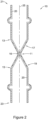
- FIG. 2 shows stent 10 including a coating layer 20 disposed along the inner surface of tubular scaffold 22.
- coating layer 20 may be an elastomeric or non-elastomeric material.
- coating layer 20 may be a polymeric material, such as silicone, polyurethane, or the like. Further, the coating layer 20 may span the spaces (e.g., openings, cells, interstices) in the wall of tubular scaffold 22 defined between adjacent filaments 14.
- the coating layer 20 may extend along and cover the inner surface and/or outer surface of tubular scaffold 22 such that the coating layer 20 spans one or more of spaces (e.g., openings, cells, interstices) between filaments 14 in the wall of tubular scaffold 22.
- spaces e.g., openings, cells, interstices
- stent 10 may have a first end 21 and a second end 23.
- first end 21 may be defined as the proximal end of stent 10 and oriented as the end of stent 10 closest to a patient's mouth and second end 23 may be defined as the distal end of stent 10 and oriented as the end of stent 10 closest to a patient's stomach.
- a first end region of stent 10 extending proximal of a proximal most flange 12 may be longer than a second end region of stent 10 extending distal of a distal most flange 12. The additional length of first end region may extend into and cover the lower esophagus in the event a small amount of stomach acid were to leak through the valve 16 (shown in FIG. 2 ).
- coating layer 20 may extend along the length of tubular scaffold 22 from first end 21 to second end 23.
- coating layer 20 may be defined as a continuous layer that extends from first end 21 to second end 23 of stent 10 and fully extends across and fills cells or interstices defined between filaments 14 of tubular scaffold 22.
- coating layer 20 may extend less than the entire length of stent 10, if desired, leaving a portion of cells or interstices defined between filaments 14 of tubular scaffold 22 unfilled or open.
- FIG. 2 shows a valve 16 positioned within the lumen of stent 10.
- valve 16 may be formed as a portion of coating layer 20.
- valve 16 may be a unitary or monolithic structure formed in conjunction with forming coating layer 20 on tubular scaffold 22.
- FIG. 2 illustrates that valve 16 may be an inwardly extending portion of coating layer 20 extending radially inward of tubular scaffold 22 at narrowed or necked region 11.
- valve 16 may be defined as a unitary or monolithic portion of coating layer 20 that extends radially inward from an inner surface of tubular scaffold 22 toward the central longitudinal axis 25 of stent 10.
- valve 16 may be defined as a monolithic portion of coating layer 20 that extends circumferentially within the lumen of stent member 10.
- valve 16 may be defined as an annular member that extends continuously around the lumen of stent 10 positioned radially inward of tubular scaffold 22 in the narrowed or necked region 11.
- valve 16 may be defined as an uninterrupted extension of coating layer 20 projecting toward central longitudinal axis 25, forming an annular rim of polymeric material radially inward of tubular scaffold 22 in the narrowed or necked region 11.
- stent 10 may include a first tapered (e.g., conical) region 17 and a second tapered (e.g., conical) region 19 with the narrowed or necked region 11 positioned therebetween.
- Both first conical region 17 and second conical region 19 may generally be shaped to taper radially inwardly in opposite directions toward the longitudinal axis 25 providing the stent 10 with an hourglass shape.
- first conical region 17 may taper radially inward from a first transition point 13 along stent 10 to valve 16 while second conical region 19 may taper radially outward from valve 16 to a second transition point 15 along stent 10.
- first conical region 17 may bear some resemblance to a cone-shaped funnel tapering from a wide portion nearest a patient's mouth to valve 16.
- second conical region 19 may bear some resemblance to a cone-shaped funnel tapering from valve 16 to a wide portion closer to a patient's stomach.
- valve 16 in a closed configuration, may taper inwardly toward central longitudinal axis 25 and close (e.g., contact, seal, etc.) onto itself such that it stops flow of material (e.g., stomach acid) from flowing through the lumen of stent 10.
- valve 16 may be desirable for valve 16 to prevent stomach acids from flowing from a patient's stomach toward the patient's mouth.
- FIG. 2 shows valve 16 in a closed configuration.
- the stent 10 may be configured to bias valve 16 to the closed configuration in a nominally deployed state.
- valve 16 it may be desirable for valve 16 to expand radially outward to permit nutritional material (e.g., food, water, etc.) to pass through the lumen of stent 10.
- nutritional material e.g., food, water, etc.
- valve 16 it is desirable for valve 16 to radially expand to permit a bolus of food or liquid to pass from a patient's mouth, through the valve 16, to the stomach.
- stent and valve examples disclosed herein may include stent filaments of tubular scaffold 22 which impart a radially compressive force inward on valve 16 to maintain the valve 16 in a closed configured while in a "nominally-deployed" state (e.g., a state in which no outside forces are acting on the stent 10 to move the valve 16 to an open configuration).
- a "nominally-deployed" state e.g., a state in which no outside forces are acting on the stent 10 to move the valve 16 to an open configuration.
- valve 16 the compressive force exerted by filaments 14 of tubular scaffold 22 on valve 16 must be low enough such that normal, peristaltic contractions associated with normal digestive processing (e.g., normal eating and digesting of food) will open valve 16, thereby permitting the bolus of nutritional material to pass through valve 16 and into the stomach (while also permit vomiting contractions to expel food back through valve 16).
- this compressive force must also be large enough to ensure the valve 16 reverts to the closed configuration when in the nominally deployed state such that stomach acids will not leak through the valve 16 from the stomach, causing symptoms of acid reflux.
- a threshold radially inward compressive force may be imparted by the filaments 14 onto the valve 16 in the nominally deployed state to hold the valve 16 in the closed configuration.
- stent 10 (including the radial compression of filaments 14) must be designed such that valve 16 remains closed in a nominally deployed state, yet opens when peristatic forces greater than the threshold inward compressive force are imparted onto the valve 16 (e.g., when peristaltic forces push a bolus of food or liquid through the valve aperture 124, thereby causing radially outward expansion forces of greater than the threshold inward compressive force to be imparted to the scaffold 22) to overcome the radially inwardly compressive forces biasing the valve 16 to the closed configuration.
- the threshold inward compressive force may be less than 0.900 N/cm 2 , less than 0.800 N/cm 2 , less than 0.700 N/cm 2 , less than 0.600 N/cm 2 , less than 0.500 N/cm 2 , or less than 0.400 N/cm 2 . Furthermore, forces less than the threshold inward compressive force (such as those imparted onto the valve 16 via acid reflux) will not cause valve 16 to open, thereby preventing stomach acids from flowing from the stomach into the esophagus.
- the threshold inward compressive force may be at least 0.200 N/cm 2 , at least 0.300 N/cm 2 , at least 0.400 N/cm 2 , at least 0.500 N/cm 2 , at least 0.600 N/cm 2 , at least 0.700 N/cm 2 , or at least 0.800 N/cm 2 .
- the threshold inward compressive force may be in the range of between 0.200 N/cm 2 to 0.900 N/cm 2 , in the range of between 0.200 N/cm 2 to 0.800 N/cm 2 , in the range of between 0.300 N/cm 2 to 0.900 N/cm 2 , in the range of between 0.300 N/cm 2 to 0.800 N/cm 2 , in the range of between 0.400 N/cm 2 to 0.800 N/cm 2 , in the range of 0.400 N/cm 2 to 0.700 N/cm 2 , for example.
- FIG. 3 and FIG. 4 illustrate valve 16 expanding radially outward to allow a bolus of nutritional material (e.g., food) 18 to pass through the lumen of stent 10 and through valve 16.
- bolus of nutritional material 18 may flow through stent 10 from a first end 21 (e.g., the end closest to a patient's mouth) to a second end 23 (e.g., the end closest to a patient's stomach).
- FIG. 4 illustrates that valve 16 may permit the material 18 to pass through the lumen of the stent 10 by expanding radially outward as the material 18 passes through valve 16. While not shown in FIG. 4 , it is contemplated that in some examples valve 16 may conform to the shape of material 18 as it passes through valve 16.
- FIG. 5 illustrates an enlarged and detailed view of example stent 10 including tubular scaffold 22 and valve 16.
- stent 10 may include a coating layer 20 covering tubular scaffold 22 and forming valve 16.
- coating layer 20 may include a thickness depicted as "X" extending along a substantial portion and covering filaments 14, such as covering an inner surface and/or outer surface of filaments 14.
- coating layer 20 is shown extending along inner surface of tubular scaffold 22, however, it is noted that additionally or alternatively coating layer 20 may extend along outer surface of tubular scaffold in some embodiments.
- the coating layer 20 may be formed from a silicone material or a polyurethane material, for instance.
- valve 16 may have an annular shape and include a circumferential, curvilinear surface extending around the longitudinal axis 25 of stent 10 whereby the coating layer 20 extends away from the inner surface of the wall of the tubular scaffold 22 (e.g., radially inward toward the longitudinal axis 25) to form valve 16.
- valve 16 may include a thickness depicted as "Y" in FIG. 5 .
- FIG. 5 illustrates that in some instances the thickness "Y" of valve 16 may be substantially equal to the thickness "X" of coating layer 20.
- coating layer 20 may maintain a substantially uniform thickness "X” along the length of scaffold 22 which extends uniformly to form the thickness "Y” of valve 16.
- the wall thickness "X" of coating layer 20 and/or the thickness "Y” defining valve 16 may be different.
- some portions of coating layer 20 and/or the thickness defining valve 16 may be thinner or thicker than other portions along stent 10.
- FIG. 5 illustrates the first tapered region 17 and the second tapered region 19, both of which may bear some resemblance to a cone-shaped funnel and together form an hourglass shape.
- stent 10 including tubular scaffold 22 and coating layer 20
- Valve 16 may taper radially inward from a first transition point 13 toward valve 16.
- Valve 16 includes a valve aperture 24.
- Valve aperture 24 may be defined as the "opening" of valve 16 (e.g., the opening of valve 16 through which nutritional material may flow). As illustrated in FIG. 5 , valve aperture 24 may be aligned with the central longitudinal axis 25.
- FIG. 5 further illustrates stent 10 (including scaffold 22 and coating layer 20) tapering radially inward from a second transition point 15 toward valve 16.
- both the first tapered region 17 and the second tapered region 19 may include a wide portion having an inner diameter (depicted in FIG. 5 as dimension "W") tapering to a narrower portion having an inner diameter (depicted in FIG. 5 as dimension "Z") less than the inner diameter of the wide portion.
- W inner diameter
- Z dimension
- the wide portion of each of the first tapered region 17 and the second tapered region 19 may be positioned adjacent to first transition point 13 and second transition point 15, respectively. Further, the narrower portion may be positioned closer to valve 16.
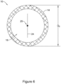
- FIG. 6 shows a cross-sectional view of stent 10 through narrowed region 11 and valve 16 taken along line 6-6 of FIG. 5 .
- line 6-6 of FIG. 5 intersects valve aperture 24 of valve 16 described above.
- valve aperture 24 may intersect the longitudinal axis 25 of stent 10.
- FIG. 6 depicts valve 16 in a closed configuration whereby filaments 14 (defining scaffold 22 described above) are imparting a radial inward compressive force onto valve 16, thereby maintaining valve aperture 24 in a closed configuration.
- FIG. 6 illustrates that narrowed region 11 of stent 10 may include an outer diameter which is depicted as "Dc" in FIG. 6 in the closed configuration.
- valve 16 may be defined as a configuration which the valve aperture 24 is closed and prevents material from flowing through the valve aperture 24.
- FIG. 6 shows the shape of valve 16 as substantially circular and extending circumferentially around the longitudinal axis 25 of the stent 10.
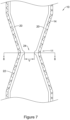
- FIG. 7 shows an enlarged view of stent 10 described above with valve 16 in an open configuration.
- FIG. 7 shows valve aperture 24 opened to a width depicted as dimension "V" in FIG. 7 .
- valve aperture 24 may open via a force being imparted radially outward (e.g., a force generated via nutritional material being driven through the valve 16 via peristalsis) which is large enough to overcome the radially inward compressive force (described above) imparted by filaments 14 of tubular scaffold 22 described above.
- FIG. 8 shows a cross-sectional view of the stent 10 through narrowed region 11 and valve 16 taken along line 8-8 of FIG. 7 .
- FIG. 8 further illustrates the valve 16 in an open configuration.
- FIG. 8 shows narrowed region 11 of stent 10 being expanded to an outer diameter depicted as "Do" in FIG. 8 .
- Diameter Do may be greater than diameter Dc described above with respect to FIG. 6 . It can be appreciated that as narrowed region 11 of stent 10 expands due to peristaltic forces acting thereupon, the outer diameter of narrowed region of stent 10 may increase from diameter Dc depicted in FIG. 6 to diameter Do depicted in FIG. 8 .
- valve 16 may shift from a closed configuration to an open configuration.
- tubular scaffold 22 radially expands in narrowed region 11 between the closed configuration to the opened configuration.
- valve aperture 24 may be an opening centered about the central longitudinal axis 25 of the lumen of stent 10.
- valves and related elements may be designed such that the structural elements defining any portion of stent 10 and/or valve 16 may be off-center.
- valve 16 may be asymmetrical about the central longitudinal axis 25 in one or more examples described herein.
- valve aperture 24 may be substantially ovular (e.g., elliptically) shaped in the open configuration.
- the ovular shape of the valve aperture 24 may reduce the force required to maintain valve 16 in closed configuration while also permitting valve 16 to open via peristaltic forces acting upon valve 16 as described above.
- FIG. 8 illustrates an ovular-shaped valve aperture 24
- the shape of valve aperture 24 may be circular, triangular, star-shaped, square, rectangular, etc.
- the valve aperture 24 may include one or more structures including flaps, leaflets, channels, slits, cuts, grooves, etc. Further, valve aperture 24 designs which combine the various geometric shapes, orientations and structures are contemplated.
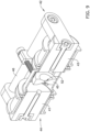
- FIGS. 9-11 illustrates an example device and method for forming (e.g., heat setting) the stent structure including stent scaffold 22 formed from filaments 14 as shown and described above.
- FIG. 9 illustrates an example stent shaping mandrel 44 which is mounted on (e.g., engaged with) an external stent fixture device 42.
- stent shaping mandrel 44 may include a first mandrel segment 41 and a second mandrel segment 43.
- External stent fixture 42 may hold first mandrel segment 41 in a fixed position relative to second mandrel segment 43 with a gap between first mandrel segment 41 and second mandrel segment 43 such that first mandrel segment 41 is spaced away from second mandrel segment 43 and not directly contacting one another.
- shaping mandrel 44 may further include a compressive member 45.
- Compressive member 45 may be positioned in the gap between the first mandrel segment 41 and the second mandrel segment 43.
- Compressive member 45 may include a narrowed aperture (e.g., opening, pinch point, etc.) 52.
- compressive member 45 may comprise a plurality of circumferentially arranged dies circumferentially arranged about a central longitudinal axis extending through first and second mandrel segments 41, 43.
- the plurality of dies may be radially movable toward and away from central longitudinal axis to adjust the size of the narrowed aperture 52.
- stent shaping mandrel 44 may be utilized to change the shape (e.g., form) of a straight, cylindrical tubular, braided stent scaffold into a more complex-shaped stent scaffold such as stent scaffold 22 shown in FIG. 1 (which includes enlarged portions 12, tapered portions 17/19 and narrowed region 11).
- a stent fixture device 42 may be utilized to manipulate the various components of the shaping mandrel 44 shown in FIG. 9 .
- the fixture device 42 may include a frame 46 attached between first mandrel segment 41 and second mandrel segment 43 and maintain first and second mandrel segments 41, 43 a fixed distance apart.
- frame 46 may include an adjustment mechanism (e.g., an adjustment screw) which may allow a user to adjust the distance between the first mandrel segment 41 and the second mandrel segment 43 to a desired fixed distance. Additionally, adjusting the distance between the first mandrel segment 41 and the second mandrel segment 43 may also alter their distance from the compressive member 45. The distance between the first mandrel segment 41 and the second mandrel segment 43 may control the shape of the first tapered region 17 and the second tapered region 19 described above with respect to FIG. 2 .
- an adjustment mechanism e.g., an adjustment screw
- FIG. 10 illustrates a cross-sectional view of the shaping mandrel 44 shown in FIG. 9 .
- FIG. 10 shows shaping mandrel 44 removed from the fixture device 42 described above.
- FIG. 10 shows shaping mandrel 44 including first mandrel segment 41, second mandrel segment 43 and compressive member 45 (positioned between first mandrel segment 41 and second mandrel segment 43).
- the compressive member 45 may include a narrowed aperture 52 (e.g., opening, pinch point, etc.). It can be appreciated that the narrowed aperture 52 of compressive member 45 may be utilized to form the narrowed region 11 of the tubular scaffold 22 shown in FIG. 1 .
- shaping mandrel 44 may include a first raised annular rim 48 and a second raised annular rim 48.
- First annular rim 48 may be provided with first mandrel segment 41 and second annular rim 48 may be provided with second mandrel segment 43.
- first and second raised annular rims 48 may be utilized to form the enlarged portions 12 or flanges of the tubular scaffold 22 shown in FIG. 1 .
- fixture device may include a first saddle 47 and a second saddle 49 configured to be placed around the first mandrel segment 41 and the second mandrel segment 43, respectively, to clamp a braided tubular scaffold to the shaping mandrel 44.
- a first end region of the braided tubular scaffold can be clamped between the first saddle 47 and the first mandrel segment 41 and a second end region of the braided tubular scaffold can be clamped between the second saddle 49 and the second mandrel segment 43.
- An example method to form tubular scaffold 22 may include positioning a straight, cylindrical tubular braided scaffold around shaping mandrel 44 (shown in FIG. 11 ) followed by the application of a heat treatment to anneal the stent filaments 14 (shown in FIG. 11 ) in a preferred shape (e.g., the shape dictated by the shaping mandrel 44).
- FIG. 11 illustrates an example cylindrical tubular braided scaffold 56 which has been positioned (e.g., disposed) around first mandrel segment 41 and second mandrel segment 43, having first and second end regions clamped to the first and second mandrel segments 41, 43 with first and second saddles 47 and 49, respectively.
- Braided tubular scaffold 56 may be formed from one or more interwoven filaments 14 formed into a cylindrical structure.
- FIG. 11 further illustrates braided scaffold 56 disposed along first mandrel segment 41 and second mandrel segment 43, with raised annular rims 48 positioned in the lumen of the braided scaffold 56 such that filaments 14 of braided scaffold 56 conform to the curvature/shape of the raised annular rims 48.
- first saddle or clamp 47 and second saddle or clamp 49 may be designed to grasp and hold the braided scaffold 56 along the outer surface of both first mandrel segment 41 and second mandrel segment 43, respectively.
- first saddle or clamp 47 may be positioned proximate the first raised annular rim 48 to instill a first ridge portion 57 in the braided scaffold 56 and second saddle or clamp 49 may be positioned proximate the second raised annular rim 48 to instill a second ridge portion 59 in the braided scaffold 56.
- Both first ridge portion 57 and second ridge portion 59 may extend radially away from other portions of braided scaffold 56.
- both first ridge portion 57 and second ridge portion 59 may extend circumferentially around the outer surface of braided segment 56.
- first ridge portion 57 and second ridge portion 59 may define a particular shape of the tubular scaffold 22 after a heat treatment is applied to the braided cylindrical scaffold 56.
- first ridge portion 57 and second ridge portion 59 may correspond to the enlarged portions or flanges 12 of the tubular scaffold 22 shown in FIGS. 1 and 2 .
- outer diameter of first end portion 21 and second end portion 23 of the tubular scaffold 22 shown in FIGS. 1 and 2 may correspond to the outer diameter of first mandrel segment 41 and second mandrel segment 43 shown in FIG. 11 .
- FIG. 11 further illustrates that shaping mandrel 44 may form a narrowed (e.g., necked) region in braided scaffold 56 by passing stent filaments 14 through the narrowed aperture 52 of the compressive member 45.
- FIG. 11 illustrates filaments 14 tapering radially inward from first mandrel segment 41 to the narrowed aperture 52 and tapering radially inward from second mandrel segment 43 to the narrowed aperture 52, with filaments of braided scaffold 56 extending through narrowed aperture 52.
- one or more dies of compressive member 45 may be actuated radially inward to radially constrain filaments 14 of braided scaffold 56 at narrowed aperture 52 to a reduced diameter, with tapered portions 60 and 62 on either side of compressive member 45.
- the compressive member 45 may restrain the diameter of the braided scaffold 56 at the necked region to a diameter of D c or less of the finished stent 10, as described above.
- first tapered portion 60 of braided scaffold 56 and second tapered portion 62 of the braided scaffold 56 may correspond to first tapered region 17 and second tapered region 19 of the tubular scaffold 22 of stent 10 shown in FIG. 1 .
- the tubular braid scaffold 56 With the filaments 14 of the tubular braid scaffold 56 held in a desired configuration with the shaping mandrel 44, the tubular braid scaffold 56 can be subjected to a heat treatment process to anneal the stent filaments 14 in a preferred formed shape. Thereafter, the braided scaffold 56 may be removed from the shaping mandrel 44, while retaining its formed shape to be used as the tubular scaffold 22 of the stent 10.
- the configuration that braided scaffold 22 embodies after being removed from the shaping mandrel 44 may be considered its "nominally deployed" configuration.
- the heat treatment process applied to the braided scaffold 56 during the forming process described above may impart a shape-memory configuration in which the scaffold 22 will revert to when unconstrained by an external force.
- This shaped memory configuration may be referred to as the stent's "nominally deployed" configuration. For example, if scaffold 22 is radially expanded to a diameter greater than its "nominally deployed" diameter, it will return to its "nominally deployed” diameter once the force which is maintaining the scaffold in the radially expanded configuration is removed.
- the nominally deployed configuration is important because it may define the threshold radial force imparted by the stent filaments 14 to maintain valve 16 in a closed configuration.
- this threshold force is the force for which the peristaltic contractions must overcome in order to open the valve 16.
- it provides the force imparted onto the valve 16 to bias the valve in the closed configuration to ensure stomach acids cannot leak back through the valve from the stomach (while a patient is lying down at rest, for example).
- FIG. 12 shows method further process for constructing coating layer 20 and valve 16 within braided scaffold 22 (after braided scaffold 56 has been removed from shaping mandrel 44 as described above).
- braided scaffold 22 may be positioned on a coating mandrel 61.
- the coating mandrel 61 may be constructed of multiple components to facilitate inserting the coating mandrel 61 into the lumen of the tubular scaffold 22 and through the narrowed region.
- a first member of the mandrel 61 may be inserted into the lumen of the tubular scaffold 22 from a first end of the tubular scaffold 22 and a second member of the mandrel 61 may be inserted into the lumen of the tubular scaffold 22 from a second end of the tubular scaffold 22.
- coating mandrel 61 may include a female member 66 coupled to a male member 64.
- the male member 64 may include a screw member 74 that may be threaded into a female threaded recess 75 located in female member 66, for example. It can be appreciated that this male-female connection may allow coating mandrel 61 to be easily separated and removed after coating material 65 is applied to braided scaffold 22.
- the outer diameter of coating mandrel 61 may be larger than the inner diameter of braided scaffold 22 being positioned thereon. It can be appreciated that designing coating mandrel 61 to have a larger outer diameter versus inner diameter of scaffold 22 may result in the scaffold 22 being positioned snug against the outer surface of coating mandrel 61 ( FIG. 12 shows scaffold 22 being positioning snug on the outer surface of coating mandrel 61). Further, the larger outer diameter of coating mandrel 61 (as compared to the inner diameter of scaffold 22) may "radially expand" the scaffold 22 as compared to its "nominally deployed" configuration (e.g., nominally deployed diameter) as discussed above.
- nominally deployed diameter e.g., nominally deployed diameter
- the coating mandrel 61 extending through the narrowed region 11, radially expands the tubular scaffold 22 at the narrowed region to a diameter greater than its diameter Dc in the nominally deployed configuration in which the valve 16 is in the closed configuration.
- scaffold 22 may radially compress to its "nominally deployed" configuration (determined via the heat treatment process described above with respect to FIG. 11 ) to bias the valve 16 to the closed configuration.
- coating mandrel 61 may be a variety of shapes and/or configurations.
- coating mandrel 61 may have a profile which substantially matches the profile of the tubular scaffold 22 being positioned thereon.
- FIG. 12 shows coating mandrel 61 including a profile which substantially matches the profile of the scaffold 22.
- FIG. 12 shows spraying element 63 applying a spray coating 65 to scaffold 22 with coating mandrel 61 extending within lumen of scaffold 22.
- the layer of material applied to scaffold 22 may correspond to coating layer 20 described in the examples above. Further, as shown in FIG. 12 , spraying element 63 may translate the full length of scaffold 22 while rotating tubular scaffold 22 and coating mandrel 61 together, depositing material corresponding to coating layer 20 accordingly.
- coating mandrel 61 may define the shape of valve 16.
- spray 65 may pass through the cells of scaffold22, forming a layer of material on the inner surface of scaffold22 at locations where scaffold 22 is spaced away from coating mandrel 61.
- FIG. 12 shows coating mandrel 61 including a recessed portion 67 spacing the surface of coating mandrel 61 away from tubular scaffold 22 at narrowed region 11.
- Recessed portion 67 may also be referred to as a "reservoir.” Further, recessed portion 67 may extend circumferentially around the entire circumference of coating mandrel 61.
- Recessed portion 67 may facilitate the formation of a portion of coating layer 20 that extends radially inward from the inner surface of tubular scaffold 22. Accordingly, the shape/contour of coating layer 20 forming the valve 16 may be determined by the profile of recessed portion 67.
- the cross-sectional shape of recessed portion 67 may be substantially ovular. It can be appreciated that the ovular shape created by recessed portion 67 may correspond to the ovular valve aperture 24 described above.
- valve 16 may be formed in the open configuration during the coating process.
- FIG. 12 shows that in some instances, the outer surface of coating mandrel 61 will be positioned and/or aligned substantially "flush" with the inner surface of scaffold 22.
- Depositing coating layer 65 along portions of coating mandrel 61 which are substantially flush with the interior surface of scaffold 56 may cause coating layer 20 to adhere to and/or form an integral interface with the inner surface of tubular scaffold 22 with the coating layer 20 filling open cells or interstices of tubular scaffold 22.
- applying spray 65 along portions of coating mandrel 61 which are not substantially flush with the interior surface of scaffold 22 may result in spray 65 passing through the cell openings of scaffold22 and being deposited along the surfaces coating mandrel 61.
- the recessed portions 67 of coating mandrel 61 may allow space for spray 65 to extend radially inward beyond the inner surface of scaffold22 such that the coating layer 20 is molded according to the shape of the recessed portion 67. It can be further appreciated from FIG. 12 that coating layer 20 applied along surface of recessed portion 67 may, therefore, form the radially inward extending portions of valve 16 (including ovular aperture 24) described above.
- FIG. 13 shows scaffold 22 after coating mandrel 61 (e.g., coating mandrel 61 described with respect to FIG. 12 ) has been removed.
- mandrel 61 e.g., coating mandrel 61 described with respect to FIG. 12
- components of mandrel 61 i.e., first and second members 64, 66
- first and second members 64, 66 may be separated to remove coating mandrel 61 from lumen of tubular scaffold 22 to provide stent 10 including scaffold 22 and coating layer 20.
- male member 64 may be unscrewed from the female member 66 and separated therefrom.
- tubular scaffold 22 may radially compress and return to its "nominally deployed" configuration.
- filaments 14 may radially compress narrowed region 11 inward to return the scaffold 22 to its nominally deployed configuration described above and collapse the valve 16 to its closed configuration.
- Valve 16 may be formed from a deflectable and/or compressible material which would deform as coating mandrel 61 is removed from scaffold 22.
- its flexibility may permit the valve aperture 24 (described above but not shown in FIG. 12 ) to close in response to scaffold 22 radially compressing and returning to its nominally deployed configuration.
- FIG. 14 illustrates an example stent delivery system 80.
- Stent delivery system may be utilized to advance and position the stent 10 described above.
- stent delivery system may include a handle member 81 coupled to an outer tubular member 82 and/or an inner member 83.
- the inner member 83 may extend through the lumen of outer tubular member 82 and is depicted as a dotted line extending through a lumen of outer tubular member 82).
- the inner member 83 may be coupled to a tip member 84.
- FIG. 15 illustrates stent 10 positioned over (e.g., surrounding) the inner member 83 (it is noted that the outer tubular member 82 may surround a portion of stent 10 and is shown in a partially retracted configuration for simplicity). As will be described in greater detail below, the inner member 83 may extend through the lumen of stent 10 (including the valve aperture 24 described above). It can further be appreciated that the handle member 81 may be utilized to retract the outer tubular member 82 relative to stent 10, inner member 83 and tip member 84 to deploy the stent 10.
- the tip member 84 may include one or more tapered portions 85 designed to allow the tip to be easily retracted back through the lumen of stent 10 after stent 10 has been deployed at a target site.
- This feature is important because valve 16 of stent 10 may be radially compressed on inner member 83 when loaded on the inner member 83 with the inner member 83 extending through valve 16. Therefore, tapered portions 85 are designed to minimize chance that tip member 84 may engage and interfere with the positioning of stent 10 as tip member 84 is retracted through the lumen of stent 10, and through valve 16.
- FIG. 16 is a cross-sectional view taken along line 16-16 of FIG. 15 .
- FIG. 16 shows stent 10 including filaments 14 encircling valve 16.
- Valve 16 may extend radially inward from the inner surface of the filaments 14 and includes an ovular valve aperture 24 through which the inner member 83 extends.
- valve 16 of stent 10 may be radially compressed on the inner member 83 in its "nominally deployed" configuration. In this configuration, the valve 16 (via the filaments 14) may exert a radially compressive force onto the surface of the inner member 83.
- valve 16 may expand radially outward to allow a bolus of nutritional material (e.g., food) 18 to pass through the lumen of stent 10 and through valve 16. Further, as discussed with respect to FIG. 2 , in some instances it may be desirable for the valve 16 to expand radially outward to permit nutritional material (e.g., food, water, etc.) to pass through the lumen of stent 10.
- nutritional material e.g., food, water, etc.
- the stent filaments of tubular scaffold 22 which impart a radially compressive force inward on valve 16 may maintain the valve 16 in a closed configured while in a "nominally-deployed" state (e.g., a state in which no outside forces are acting on the stent 10 to move the valve 16 to an open configuration).
- a "nominally-deployed" state e.g., a state in which no outside forces are acting on the stent 10 to move the valve 16 to an open configuration.
- the compressive force exerted by filaments 14 of tubular scaffold 22 on valve 16 must be low enough such that normal, peristaltic contractions associated with normal digestive processing (e.g., normal eating and digesting of food) will open valve 16, thereby permitting the bolus of nutritional material to pass through valve 16 and into the stomach (while also permit vomiting contractions to expel food back through valve 16.
- stent 10 when designing stent 10 (shown in FIG. 1 ), it may be beneficial to understand the radially outward forces generated by a bolus of nutritional material passing through portions of stent 10. For example, it may be beneficial to understand the minimum radially outward forces generated by a bolus of nutritional material passing through the narrowed region 11 of the stent 10. It can be appreciated from the above discussion that the minimum radially outward forces generated by the bolus of material passing through the narrowed region 11 of the stent 10 may correspond to the maximum compressive forces exerted by filaments 14 of the tubular scaffold 22 on the valve 16.
- stent 10 may be designed such that the maximum compressive forces exerted by filaments 14 of tubular scaffold 22 on valve 16 must be low enough to permit the minimum radially outward force generated by bolus of material to pass through the stent 10.
- the stent 10 may be designed such that the maximum radially compressive force exerted by the filaments 14 of tubular scaffold 22 on valve 16 to close the valve 16 in a nominally-deployed state are less than the minimum radially outward force generated by a bolus of material passing through the stent 10, in order to ensure the valve 16 opens sufficiently to allow the bolus of material to pass through the stent 10.
- FIG. 17 illustrates an example bolus force test fixture 90.
- the test fixture 90 may be utilized to determine the radially outward forces generated by a representative bolus of material passing through the stent 10.
- the test fixture 90 may include a first stent engagement member 94a and a second stent engagement member 94b, each of which are secured to a base 92.
- the first stent engagement member 94a and the second stent engagement member 94b may be aligned with one another along a longitudinal axis 93. As illustrated in FIG.
- each of the first stent engagement member 94a and the second stent engagement member 94b may be secured to the base 92 via a first engagement mount or strap 97a (utilized to secure the first stent engagement member 94a to the base 92) and a second engagement mount or strap 97b (utilized to secure the second stent engagement member 94b to the base 92).
- Each of the first and the second stent engagement members 94a, 94b may be shaped such that they are designed to engage the first end 21 and the second end 23 of the stent 10 (not shown in FIG. 17 , but shown in FIG. 1 ).
- each of the first and the second stent engagement members 94a, 94b may include a first protrusion 95a (extending radially outward from the outer surface of the stent engagement member 94a) and a second protrusion 95b (extending radially outward from the outer surface of the stent engagement member 94a).
- each of the first engagement member 94a and the second engagement member 94b may be designed to mate with the first end 21 and the second end 23 of the stent 10 (not shown in FIG. 17 , but shown in FIG. 1 ).
- the first protrusion 95a and the second protrusion 95b may each be designed to mate with the enlarged portions 12 of the stent 10.
- each of the first stent engagement member 94a and the second stent engagement member 94b may include a first lumen 92a and a second lumen 92b, respectively. It can be appreciated that each of the first lumen 92a and the second lumen 92b may be designed (e.g., sized) such that a bolus member 96 may pass therethrough.
- the bolus member 96 may resemble a spherically shaped ball designed to mimic (e.g., resemble, etc.) a bolus of nutritional material which may pass through the stent 10 (shown in FIG. 1 ). While FIG. 17 illustrates that bolus member 96 spherically-shaped, other shapes are contemplated to mimic various types of nutritional material passing through the stent 10.
- FIG. 17 illustrates that the bolus member 96 may be attached to a pull member 98 which may be designed to pass through the first lumen 92a and the second lumen 92b of the first stent engagement member 94a and the second stent engagement member 94b, respectively.
- the pull member 98 may be utilized to pull the bolus member 96 along the axis 93 through each of the first stent engagement member 94a and the second stent engagement member 94b, and thus through the valve 16 of a stent 10 mounted to the fixture 90.
- FIG. 18 and FIG. 19 illustrate the example bolus member 96 being pulled through the stent 10 described above.
- FIG. 18 illustrates the first end 21 of the stent 10 mounted to the first engagement member 94a and the second end 23 of the stent 10 mounted to the second engagement member 94b.
- FIG. 18 illustrates each of the first engagement strap 97a and a second engagement strap 97b securing the first engagement member 94a and the second engagement member 94b to the base 92.
- FIG. 18 illustrates the bolus member 96 aligned with the first lumen 94a along the axis 93. Further, the pull member 98 is attached to the bolus member 96 while also extending through the first lumen 92a of the first engagement member 94a, the stent 10 (including the narrowed region 11) and through the second lumen 92b of the second engagement member 94b.
- FIG. 19 illustrates the bolus member 96 being pulled through the stent 10.
- FIG. 19 illustrates bolus member 96 being pulled through the narrowed region 11 of stent 10.
- a force measurement machine e.g., a tensile testing machine, Instron ® machine, etc.
- the force testing machine is not shown in FIG. 18 or FIG. 19 ).
- the base 92 may be secured to one portion of the force testing machine while the pull member 98 may be attached to another portion of the force testing machine.
- the force testing machine may be designed to "pull" the pull member 98 (which is attached to the bolus member 96) through the stent 10, as indicated by the arrow 99 in FIG. 19 .
- the force testing machine may continuously record the radially outward forces generated by the bolus member 96 as it advances through the stent 10, as a function of the axial force measured.
- the speed with which the bolus member 96 is pulled through the stent 10 may be varied to better understand how the stent reacts (e.g., the force variations placed upon the stent 10) as the bolus member 96 passes through the stent 10 at varying speeds.
- the test methodology described above has shown that the radially outward forces generated by the bolus member 96 having a diameter of 15 mm may be in the range of between 2.40 N to 4.70 N as the bolus member 96 is pulled through the stent 10 at a speed of 5 mm/s, in the range of between 2.20 N to 3.40 N as the bolus member 96 is pulled through the stent 10 at a speed of 7 mm/s, in the range of between 2.20 N to 3.30 N as the bolus member 96 is pulled through the stent 10 at a speed of 10 mm/s, in the range of between 2.00 N to 3.30 N as the bolus member 96 is pulled through the stent 10 at a speed of 12 mm/s, and in the range of between 2.0 N to 3.30 N as the bolus member 96 is pulled through the stent 10 at a speed of 15 mm/s, for example.
- the filaments 14 should exert a radially inward compressive force of less than 2.0 N, less than 1.5 N, or less than 1.0 N in a nominally deployed state to ensure that the valve 16 will open sufficiently to permit a bolus of material to pass through the valve 16.
Landscapes
- Health & Medical Sciences (AREA)
- Engineering & Computer Science (AREA)
- Biomedical Technology (AREA)
- Cardiology (AREA)
- Oral & Maxillofacial Surgery (AREA)
- Transplantation (AREA)
- Heart & Thoracic Surgery (AREA)
- Vascular Medicine (AREA)
- Life Sciences & Earth Sciences (AREA)
- Animal Behavior & Ethology (AREA)
- General Health & Medical Sciences (AREA)
- Public Health (AREA)
- Veterinary Medicine (AREA)
- Gastroenterology & Hepatology (AREA)
- Pulmonology (AREA)
- Mechanical Engineering (AREA)
- Prostheses (AREA)
- Media Introduction/Drainage Providing Device (AREA)
Claims (14)
- Endoprothèse expansible (10) comprenant :un échafaudage tubulaire (22) formé avec un ou plusieurs filaments entrelacés (14), l'échafaudage tubulaire (22) comprenant une surface interne ; etune valve flexible (16) s'étendant radialement vers l'intérieur à partir de la surface interne de l'échafaudage (22) ;dans laquelle la valve (16) est configurée pour se déplacer entre une configuration fermée et une configuration ouverte ;dans laquelle les un ou plusieurs filaments (14) de l'échafaudage (22) sollicitent la valve (16) dans la configuration fermée, tout en étant dans un état nominalement déployé,dans laquelle l'échafaudage tubulaire (22) comprend une première région progressivement rétrécie (17) et une deuxième région progressivement rétrécie (19), et dans laquelle la valve (16) est positionnée entre la première région progressivement rétrécie (17) et la deuxième région progressivement rétrécie (19).
- Endoprothèse selon la revendication 1, dans laquelle la valve (16) se déplace de la configuration fermée à la configuration ouverte en raison d'une force péristaltique appliquée sur l'échafaudage tubulaire (22).
- Endoprothèse selon l'une quelconque des revendications 1 à 2, dans laquelle la valve (16) comprend une ouverture de valve s'étendant à travers cette dernière et dans laquelle l'ouverture de valve est de forme ovale dans la configuration ouverte.
- Endoprothèse selon l'une quelconque des revendications 1 à 3, dans laquelle la première région progressivement rétrécie (17) est configurée pour acheminer le matériau vers la valve (16).
- Endoprothèse selon l'une quelconque des revendications 1 à 4, dans laquelle les un ou plusieurs filaments (14) de l'échafaudage (22) sont configurés pour se dilater radialement afin de déplacer la valve (16) de la configuration fermée à la configuration ouverte, lorsqu'ils sont soumis à une force de dilatation radiale de 0,800 N/cm2 ou plus.
- Endoprothèse selon l'une quelconque des revendications 1 à 5, comprenant en outre un revêtement (20) disposé le long des un ou plusieurs filaments (14), et dans laquelle la valve (16) est formée à partir d'une partie du revêtement (20).
- Endoprothèse selon l'une quelconque des revendications 1 à 6, dans laquelle la valve (16) est une valve à deux voies configurée pour permettre le passage du matériau à travers la valve (16) dans une première direction et dans une deuxième direction, et dans laquelle la première direction est opposée à la deuxième direction.
- Procédé pour fabriquer une endoprothèse (10), le procédé comprenant les faits de :former un échafaudage tubulaire (22), dans lequel l'échafaudage tubulaire (22) comprend une première extrémité (21), une deuxième extrémité (23) et une région rétrécie (11) positionnée entre la première extrémité (21) et la deuxième extrémité (23) ;positionner l'échafaudage tubulaire (22) sur un mandrin de revêtement (61), de sorte que le mandrin de revêtement (61) dilate radialement la région rétrécie (11), dans lequel l'échafaudage tubulaire (22) est espacé du mandrin de revêtement (61) au niveau de la région rétrécie (11) ;appliquer un revêtement (65) sur l'échafaudage tubulaire (22) alors que l'échafaudage tubulaire (22) est positionné sur le mandrin de revêtement (61), dans lequel l'application du revêtement (65) sur l'échafaudage tubulaire (22) comprend la formation d'une valve (16) dans la région rétrécie (11) de l'échafaudage tubulaire (22) ;après quoi, retirer l'échafaudage tubulaire (22) du mandrin de revêtement (61), dans lequel l'échafaudage tubulaire (22) se replie radialement au niveau de la région rétrécie (11) afin de solliciter la valve (16) dans une configuration fermée après avoir été retiré du mandrin de revêtement (61).
- Procédé selon la revendication 9, dans lequel la formation de l'échafaudage tubulaire (22) comprend le tressage d'au moins deux filaments d'endoprothèse ou plus (14) ensemble.
- Procédé selon l'une quelconque des revendications 8 à 9, dans lequel la formation de l'échafaudage tubulaire (22) comprend en outre le positionnement de l'échafaudage tubulaire (22) sur un mandrin de formage (44) et dans lequel le mandrin de formage (44) est configuré pour pincer radialement les un ou plusieurs filaments (14) afin de créer la région rétrécie (11).
- Procédé selon la revendication 10, dans lequel la formation de l'échafaudage tubulaire (22) comprend en outre le traitement thermique de l'échafaudage tubulaire (22) alors que l'échafaudage tubulaire (22) est positionné sur le mandrin de formage (44).
- Procédé selon l'une quelconque des revendications 8 à 11, dans lequel l'application du revêtement (65) sur l'échafaudage tubulaire (22) comprend en outre la pulvérisation du revêtement (65) sur l'échafaudage tubulaire (22).
- Procédé selon l'une quelconque des revendications 8 à 12, dans lequel la valve (16) a une ouverture de forme ovale dans une configuration ouverte.
- Endoprothèse expansible (10) comprenant :un échafaudage tubulaire (22) tressé formé avec une pluralité de filaments (14) entrelacés, l'échafaudage tubulaire (22) comprend une première extrémité (21), une deuxième extrémité (23) et une lumière s'étendant à travers, l'échafaudage tubulaire (22) comprenant en outre une région rétrécie (11) positionnée entre la première extrémité (21) et la deuxième extrémité (23) ; etune valve flexible (16) positionnée à l'intérieur de la lumière au niveau de la région rétrécie (11) ;dans laquelle l'échafaudage tubulaire (22) comprend une première région progressivement rétrécie (17) et une deuxième région progressivement rétrécie (19), et dans laquelle la valve (16) est positionnée entre la première région progressivement rétrécie (17) et la deuxième région progressivement rétrécie (19) ;dans laquelle la pluralité de filaments (14) entrelacés applique une force radialement compressive sur la valve (16) afin de solliciter la valve (16) dans une configuration fermée, alors que l'endoprothèse (10) est dans un état nominalement déployé.
Applications Claiming Priority (2)
| Application Number | Priority Date | Filing Date | Title |
|---|---|---|---|
| US201762579990P | 2017-11-01 | 2017-11-01 | |
| PCT/US2018/058431 WO2019089741A1 (fr) | 2017-11-01 | 2018-10-31 | Endoprothèse œsophagienne comprenant un élément de vanne |
Publications (2)
| Publication Number | Publication Date |
|---|---|
| EP3681436A1 EP3681436A1 (fr) | 2020-07-22 |
| EP3681436B1 true EP3681436B1 (fr) | 2024-10-16 |
Family
ID=64607293
Family Applications (1)
| Application Number | Title | Priority Date | Filing Date |
|---|---|---|---|
| EP18815058.5A Active EP3681436B1 (fr) | 2017-11-01 | 2018-10-31 | Endoprothèse sophagienne comprenant un élément de vanne |
Country Status (4)
| Country | Link |
|---|---|
| US (2) | US10888444B2 (fr) |
| EP (1) | EP3681436B1 (fr) |
| CN (1) | CN111315319B (fr) |
| WO (1) | WO2019089741A1 (fr) |
Families Citing this family (8)
| Publication number | Priority date | Publication date | Assignee | Title |
|---|---|---|---|---|
| EP3681436B1 (fr) * | 2017-11-01 | 2024-10-16 | Boston Scientific Scimed Inc. | Endoprothèse sophagienne comprenant un élément de vanne |
| CN113727658A (zh) * | 2018-12-04 | 2021-11-30 | 脑部保护私人有限公司 | 包括用于治疗病症的可植入阻尼装置和治疗剂的组合疗法及相关系统和使用方法 |
| CN110726086A (zh) * | 2019-09-19 | 2020-01-24 | 花诗影 | 一种沙漏灯 |
| CN113143555B (zh) * | 2020-06-30 | 2025-09-12 | 微创神通医疗科技(上海)有限公司 | 一种血管支架 |
| EP4210640A1 (fr) * | 2020-09-14 | 2023-07-19 | Boston Scientific Scimed Inc. | Endoprothèses et procédés d'utilisation et de fabrication d'endoprothèses avec des éléments de rétention améliorés |
| EP4475797A1 (fr) * | 2022-01-24 | 2024-12-18 | Vactronix Scientific, LLC | Valvules cardiaques à alvéoles sollicitées et procédés de fabrication de telles valvules cardiaques |
| CN118973523A (zh) * | 2022-02-08 | 2024-11-15 | 波士顿科学国际有限公司 | 用于闭塞解剖通道的装置、系统及方法 |
| CN115227445B (zh) * | 2022-06-28 | 2023-09-19 | 柏为(武汉)医疗科技股份有限公司 | 一种咽鼓管支架及其组件 |
Family Cites Families (78)
| Publication number | Priority date | Publication date | Assignee | Title |
|---|---|---|---|---|
| US5064435A (en) | 1990-06-28 | 1991-11-12 | Schneider (Usa) Inc. | Self-expanding prosthesis having stable axial length |
| US5989280A (en) | 1993-10-22 | 1999-11-23 | Scimed Lifesystems, Inc | Stent delivery apparatus and method |
| RU2089131C1 (ru) | 1993-12-28 | 1997-09-10 | Сергей Апполонович Пульнев | Стент |
| US5575816A (en) | 1994-08-12 | 1996-11-19 | Meadox Medicals, Inc. | High strength and high density intraluminal wire stent |
| BE1009278A3 (fr) | 1995-04-12 | 1997-01-07 | Corvita Europ | Tuteur auto-expansible pour dispositif medical a introduire dans une cavite d'un corps, et dispositif medical muni d'un tel tuteur. |
| BE1009277A3 (fr) | 1995-04-12 | 1997-01-07 | Corvita Europ | Tuteur auto-expansible pour dispositif medical a introduire dans une cavite d'un corps, et son procede de preparation. |
| JPH09215753A (ja) | 1996-02-08 | 1997-08-19 | Schneider Usa Inc | チタン合金製自己拡張型ステント |
| WO1998046168A1 (fr) | 1997-04-15 | 1998-10-22 | Schneider (Usa) Inc | Protheses avec brins croises selectivement soudes |
| US5836966A (en) | 1997-05-22 | 1998-11-17 | Scimed Life Systems, Inc. | Variable expansion force stent |
| DE69732229T2 (de) | 1997-07-17 | 2005-12-29 | Schneider (Europe) Gmbh | Stent sowie Herstellungsverfahren dafür |
| US6254642B1 (en) | 1997-12-09 | 2001-07-03 | Thomas V. Taylor | Perorally insertable gastroesophageal anti-reflux valve prosthesis and tool for implantation thereof |
| US6626939B1 (en) | 1997-12-18 | 2003-09-30 | Boston Scientific Scimed, Inc. | Stent-graft with bioabsorbable structural support |
| US6264689B1 (en) | 1998-03-31 | 2001-07-24 | Scimed Life Systems, Incorporated | Low profile medical stent |
| US6520983B1 (en) | 1998-03-31 | 2003-02-18 | Scimed Life Systems, Inc. | Stent delivery system |
| US5980533A (en) | 1998-06-09 | 1999-11-09 | Scimed Life Systems, Inc. | Stent delivery system |
| US6120522A (en) | 1998-08-27 | 2000-09-19 | Scimed Life Systems, Inc. | Self-expanding stent delivery catheter |
| DE69913163T2 (de) | 1998-08-31 | 2004-09-09 | Wilson-Cook Medical Inc. | Antirückflussspeiseröhrenprothese |
| US7018401B1 (en) | 1999-02-01 | 2006-03-28 | Board Of Regents, The University Of Texas System | Woven intravascular devices and methods for making the same and apparatus for delivery of the same |
| AU6000200A (en) | 1999-07-16 | 2001-02-05 | Biocompatibles Limited | Braided stent |
| US20030055492A1 (en) * | 1999-08-20 | 2003-03-20 | Shaolian Samuel M. | Transluminally implantable venous valve |
| US6409753B1 (en) | 1999-10-26 | 2002-06-25 | Scimed Life Systems, Inc. | Flexible stent |
| US6585758B1 (en) | 1999-11-16 | 2003-07-01 | Scimed Life Systems, Inc. | Multi-section filamentary endoluminal stent |
| US6468303B1 (en) | 2000-03-27 | 2002-10-22 | Aga Medical Corporation | Retrievable self expanding shunt |
| US6494909B2 (en) * | 2000-12-01 | 2002-12-17 | Prodesco, Inc. | Endovascular valve |
| US6620122B2 (en) | 2001-04-26 | 2003-09-16 | Scimed Life Systems, Inc. | Gastric pseudocyst drainage and stent delivery system for use therein |
| WO2003000142A2 (fr) | 2001-06-20 | 2003-01-03 | Park Medical, Llc. | Dispositif anastomotique |
| US7175655B1 (en) | 2001-09-17 | 2007-02-13 | Endovascular Technologies, Inc. | Avoiding stress-induced martensitic transformation in nickel titanium alloys used in medical devices |
| US6790237B2 (en) * | 2001-10-09 | 2004-09-14 | Scimed Life Systems, Inc. | Medical stent with a valve and related methods of manufacturing |
| US20030083734A1 (en) | 2001-10-25 | 2003-05-01 | Curative Ag | Stent |
| US8221482B2 (en) | 2002-01-28 | 2012-07-17 | Orbusneich Medical, Inc. | Flared ostial endoprosthesis and delivery system |
| US7001425B2 (en) | 2002-11-15 | 2006-02-21 | Scimed Life Systems, Inc. | Braided stent method for its manufacture |
| US20040102855A1 (en) | 2002-11-21 | 2004-05-27 | Scimed Life Systems, Inc. | Anti-reflux stent |
| US7608114B2 (en) | 2002-12-02 | 2009-10-27 | Gi Dynamics, Inc. | Bariatric sleeve |
| US20050075725A1 (en) * | 2003-10-02 | 2005-04-07 | Rowe Stanton J. | Implantable prosthetic valve with non-laminar flow |
| EP1708655A1 (fr) | 2003-12-09 | 2006-10-11 | GI Dynamics, Inc. | Dispositif s'ancrant dans le tube digestif et son procede d'ancrage |
| US7763011B2 (en) | 2003-12-22 | 2010-07-27 | Boston Scientific Scimed, Inc. | Variable density braid stent |
| US20050228413A1 (en) | 2004-04-12 | 2005-10-13 | Binmoeller Kenneth F | Automated transluminal tissue targeting and anchoring devices and methods |
| US8425539B2 (en) | 2004-04-12 | 2013-04-23 | Xlumena, Inc. | Luminal structure anchoring devices and methods |
| EP1799145B1 (fr) | 2004-09-17 | 2016-12-21 | GI Dynamics, Inc. | Ancrages gastro-intestinaux |
| WO2006053270A2 (fr) | 2004-11-10 | 2006-05-18 | Boston Scientific Limited | Endoprothese vasculaire atraumatique a force de deploiement reduite, procede de fabrication de cette derniere et procede et appareil de deploiement et de positionnement de l'endoprothese vasculaire |
| US7670369B2 (en) | 2005-10-13 | 2010-03-02 | Cook Incorporated | Endoluminal prosthesis |
| CN100362971C (zh) | 2005-11-16 | 2008-01-23 | 程英升 | 贲门支架 |
| US20070179590A1 (en) | 2005-12-29 | 2007-08-02 | Wenfeng Lu | Hybrid intraluminal device with varying expansion force |
| US8105392B2 (en) | 2006-11-08 | 2012-01-31 | Boston Scientific Scimed, Inc. | Pyloric obesity valve |
| US8221505B2 (en) | 2007-02-22 | 2012-07-17 | Cook Medical Technologies Llc | Prosthesis having a sleeve valve |
| US20080228256A1 (en) | 2007-03-13 | 2008-09-18 | Medtronic Vascular, Inc. | Braided Flange Branch Graft for Branch Vessel |
| BRPI0819217B8 (pt) | 2007-10-25 | 2021-06-22 | Symetis Sa | válvula de substituição para uso dentro de um corpo humano, sistema para substituir uma válvula dentro de um corpo humano e sistema de liberação da válvula cardíaca com stent |
| US8623071B2 (en) | 2008-01-07 | 2014-01-07 | DePuy Synthes Products, LLC | Radiopaque super-elastic intravascular stent |
| US7972378B2 (en) * | 2008-01-24 | 2011-07-05 | Medtronic, Inc. | Stents for prosthetic heart valves |
| CA2715448C (fr) | 2008-02-25 | 2017-06-13 | Medtronic Vascular Inc. | Dispositifs de reduction infundibulaires |
| US20090248142A1 (en) * | 2008-03-25 | 2009-10-01 | Medtronic Vascular, Inc. | Methods, Devices and Systems for Treating Venous Insufficiency |
| US20090276040A1 (en) | 2008-05-01 | 2009-11-05 | Edwards Lifesciences Corporation | Device and method for replacing mitral valve |
| US8454632B2 (en) | 2008-05-12 | 2013-06-04 | Xlumena, Inc. | Tissue anchor for securing tissue layers |
| US20090281379A1 (en) | 2008-05-12 | 2009-11-12 | Xlumena, Inc. | System and method for transluminal access |
| US8114147B2 (en) | 2008-06-16 | 2012-02-14 | Boston Scientific Scimed, Inc. | Continuous double layered stent for migration resistance |
| US20100114327A1 (en) | 2008-06-20 | 2010-05-06 | Vysera Biomedical Limited | Valve |
| US8151682B2 (en) | 2009-01-26 | 2012-04-10 | Boston Scientific Scimed, Inc. | Atraumatic stent and method and apparatus for making the same |
| CA2756991A1 (fr) | 2009-04-03 | 2010-10-07 | Metamodix, Inc. | Protheses gastro-intestinales modulaires |
| US9173760B2 (en) | 2009-04-03 | 2015-11-03 | Metamodix, Inc. | Delivery devices and methods for gastrointestinal implants |
| WO2010138277A1 (fr) | 2009-05-29 | 2010-12-02 | Xlumena, Inc. | Appareil et méthode de déploiement d'une endoprothèse à travers des couches de tissu adjacent |
| US20100305590A1 (en) | 2009-05-29 | 2010-12-02 | Gi Dynamics, Inc. | Transpyloric Anchoring |
| US9211182B2 (en) | 2009-11-20 | 2015-12-15 | E2, Llc | Anti-reflux devices and methods for treating gastro-esophageal reflux disease (GERD) |
| US8696698B2 (en) * | 2009-12-02 | 2014-04-15 | Surefire Medical, Inc. | Microvalve protection device and method of use for protection against embolization agent reflux |
| US20110190905A1 (en) | 2009-12-18 | 2011-08-04 | Vysera Biomedical Limited | Gastrointestinal implant |
| WO2011136963A1 (fr) | 2010-04-30 | 2011-11-03 | Boston Scientific Scimed, Inc. | Endoprothèse métabolique duodénale |
| US9526648B2 (en) | 2010-06-13 | 2016-12-27 | Synerz Medical, Inc. | Intragastric device for treating obesity |
| RU2626885C2 (ru) | 2011-12-19 | 2017-08-02 | Колопласт А/С | Внутрипросветный протез и желудочно-кишечный имплантат |
| FR2984724B1 (fr) | 2011-12-23 | 2014-01-24 | Assist Publ Hopitaux De Paris | Prothese expansive destinee a etre implantee dans le tube digestif d'un patient. |
| EP3156006B1 (fr) | 2012-03-16 | 2022-05-18 | Terumo Corporation | Endoprothèse vasculaire et dispositif de mise en place d'une endoprothèse vasculaire |
| US9427303B2 (en) * | 2012-04-27 | 2016-08-30 | Cook Medical Technologies Llc | Anti-aspiration valve |
| CN202637199U (zh) * | 2012-05-07 | 2013-01-02 | 同济大学 | 一种螺旋形可降解食管支架 |
| CN103908362A (zh) * | 2013-01-08 | 2014-07-09 | 杨廷旭 | 覆膜双瓣抗返流镍钛记忆合金食管支架 |
| EP3193780A1 (fr) | 2014-09-18 | 2017-07-26 | Boston Scientific Scimed Inc. | Dispositif permettant au sphincter pylorique de fonctionner normalement pour des endoprothèses bariatriques |
| US9693860B2 (en) * | 2014-12-01 | 2017-07-04 | Medtronic, Inc. | Segmented transcatheter valve prosthesis having an unsupported valve segment |
| WO2017155885A1 (fr) * | 2016-03-07 | 2017-09-14 | Boston Scientific Scimed, Inc. | Endoprothèse œsophagienne comprenant un élément de vanne |
| WO2018089560A1 (fr) * | 2016-11-09 | 2018-05-17 | Boston Scientific Scimed, Inc. | Système d'ancrage d'endoprothèse vasculaire |
| EP3681436B1 (fr) * | 2017-11-01 | 2024-10-16 | Boston Scientific Scimed Inc. | Endoprothèse sophagienne comprenant un élément de vanne |
| US11517430B1 (en) * | 2022-01-24 | 2022-12-06 | Vactronix Scientific, Llc | Biased cell, devices using same, and methods of making and using same |
-
2018
- 2018-10-31 EP EP18815058.5A patent/EP3681436B1/fr active Active
- 2018-10-31 CN CN201880071405.0A patent/CN111315319B/zh active Active
- 2018-10-31 WO PCT/US2018/058431 patent/WO2019089741A1/fr not_active Ceased
- 2018-10-31 US US16/176,451 patent/US10888444B2/en active Active
-
2020
- 2020-12-16 US US17/123,449 patent/US11771574B2/en active Active
Also Published As
| Publication number | Publication date |
|---|---|
| US10888444B2 (en) | 2021-01-12 |
| US20210186723A1 (en) | 2021-06-24 |
| US20190125558A1 (en) | 2019-05-02 |
| US11771574B2 (en) | 2023-10-03 |
| WO2019089741A1 (fr) | 2019-05-09 |
| CN111315319A (zh) | 2020-06-19 |
| EP3681436A1 (fr) | 2020-07-22 |
| CN111315319B (zh) | 2022-10-18 |
Similar Documents
| Publication | Publication Date | Title |
|---|---|---|
| EP3681436B1 (fr) | Endoprothèse sophagienne comprenant un élément de vanne | |
| US20250152325A1 (en) | Esophageal stent including an inner liner | |
| EP3600149B1 (fr) | Système de stent récupérable | |
| US20230363885A1 (en) | Esophageal stent including a valve member | |
| KR102688148B1 (ko) | 이동-방지 능력을 포함하는 스텐트 | |
| US20250082456A1 (en) | Stent with dynamic anti-migration properties |
Legal Events
| Date | Code | Title | Description |
|---|---|---|---|
| STAA | Information on the status of an ep patent application or granted ep patent |
Free format text: STATUS: UNKNOWN |
|
| STAA | Information on the status of an ep patent application or granted ep patent |
Free format text: STATUS: THE INTERNATIONAL PUBLICATION HAS BEEN MADE |
|
| PUAI | Public reference made under article 153(3) epc to a published international application that has entered the european phase |
Free format text: ORIGINAL CODE: 0009012 |
|
| STAA | Information on the status of an ep patent application or granted ep patent |
Free format text: STATUS: REQUEST FOR EXAMINATION WAS MADE |
|
| 17P | Request for examination filed |
Effective date: 20200416 |
|
| AK | Designated contracting states |
Kind code of ref document: A1 Designated state(s): AL AT BE BG CH CY CZ DE DK EE ES FI FR GB GR HR HU IE IS IT LI LT LU LV MC MK MT NL NO PL PT RO RS SE SI SK SM TR |
|
| AX | Request for extension of the european patent |
Extension state: BA ME |
|
| DAV | Request for validation of the european patent (deleted) | ||
| DAX | Request for extension of the european patent (deleted) | ||
| GRAP | Despatch of communication of intention to grant a patent |
Free format text: ORIGINAL CODE: EPIDOSNIGR1 |
|
| STAA | Information on the status of an ep patent application or granted ep patent |
Free format text: STATUS: GRANT OF PATENT IS INTENDED |
|
| INTG | Intention to grant announced |
Effective date: 20240507 |
|
| GRAS | Grant fee paid |
Free format text: ORIGINAL CODE: EPIDOSNIGR3 |
|
| GRAA | (expected) grant |
Free format text: ORIGINAL CODE: 0009210 |
|
| STAA | Information on the status of an ep patent application or granted ep patent |
Free format text: STATUS: THE PATENT HAS BEEN GRANTED |
|
| P01 | Opt-out of the competence of the unified patent court (upc) registered |
Free format text: CASE NUMBER: APP_50110/2024 Effective date: 20240904 |
|
| AK | Designated contracting states |
Kind code of ref document: B1 Designated state(s): AL AT BE BG CH CY CZ DE DK EE ES FI FR GB GR HR HU IE IS IT LI LT LU LV MC MK MT NL NO PL PT RO RS SE SI SK SM TR |
|
| REG | Reference to a national code |
Ref country code: GB Ref legal event code: FG4D |
|
| REG | Reference to a national code |
Ref country code: CH Ref legal event code: EP |
|
| REG | Reference to a national code |
Ref country code: IE Ref legal event code: FG4D |
|
| REG | Reference to a national code |
Ref country code: DE Ref legal event code: R096 Ref document number: 602018075569 Country of ref document: DE |
|
| REG | Reference to a national code |
Ref country code: NL Ref legal event code: FP |
|
| REG | Reference to a national code |
Ref country code: LT Ref legal event code: MG9D |
|
| REG | Reference to a national code |
Ref country code: AT Ref legal event code: MK05 Ref document number: 1732321 Country of ref document: AT Kind code of ref document: T Effective date: 20241016 |
|
| PG25 | Lapsed in a contracting state [announced via postgrant information from national office to epo] |
Ref country code: HR Free format text: LAPSE BECAUSE OF FAILURE TO SUBMIT A TRANSLATION OF THE DESCRIPTION OR TO PAY THE FEE WITHIN THE PRESCRIBED TIME-LIMIT Effective date: 20241016 Ref country code: PT Free format text: LAPSE BECAUSE OF FAILURE TO SUBMIT A TRANSLATION OF THE DESCRIPTION OR TO PAY THE FEE WITHIN THE PRESCRIBED TIME-LIMIT Effective date: 20250217 Ref country code: IS Free format text: LAPSE BECAUSE OF FAILURE TO SUBMIT A TRANSLATION OF THE DESCRIPTION OR TO PAY THE FEE WITHIN THE PRESCRIBED TIME-LIMIT Effective date: 20250216 |
|
| PG25 | Lapsed in a contracting state [announced via postgrant information from national office to epo] |
Ref country code: FI Free format text: LAPSE BECAUSE OF FAILURE TO SUBMIT A TRANSLATION OF THE DESCRIPTION OR TO PAY THE FEE WITHIN THE PRESCRIBED TIME-LIMIT Effective date: 20241016 |
|
| PG25 | Lapsed in a contracting state [announced via postgrant information from national office to epo] |
Ref country code: BG Free format text: LAPSE BECAUSE OF FAILURE TO SUBMIT A TRANSLATION OF THE DESCRIPTION OR TO PAY THE FEE WITHIN THE PRESCRIBED TIME-LIMIT Effective date: 20241016 |
|
| PG25 | Lapsed in a contracting state [announced via postgrant information from national office to epo] |
Ref country code: ES Free format text: LAPSE BECAUSE OF FAILURE TO SUBMIT A TRANSLATION OF THE DESCRIPTION OR TO PAY THE FEE WITHIN THE PRESCRIBED TIME-LIMIT Effective date: 20241016 |
|
| PG25 | Lapsed in a contracting state [announced via postgrant information from national office to epo] |
Ref country code: NO Free format text: LAPSE BECAUSE OF FAILURE TO SUBMIT A TRANSLATION OF THE DESCRIPTION OR TO PAY THE FEE WITHIN THE PRESCRIBED TIME-LIMIT Effective date: 20250116 |
|
| PG25 | Lapsed in a contracting state [announced via postgrant information from national office to epo] |
Ref country code: LV Free format text: LAPSE BECAUSE OF FAILURE TO SUBMIT A TRANSLATION OF THE DESCRIPTION OR TO PAY THE FEE WITHIN THE PRESCRIBED TIME-LIMIT Effective date: 20241016 Ref country code: AT Free format text: LAPSE BECAUSE OF FAILURE TO SUBMIT A TRANSLATION OF THE DESCRIPTION OR TO PAY THE FEE WITHIN THE PRESCRIBED TIME-LIMIT Effective date: 20241016 Ref country code: GR Free format text: LAPSE BECAUSE OF FAILURE TO SUBMIT A TRANSLATION OF THE DESCRIPTION OR TO PAY THE FEE WITHIN THE PRESCRIBED TIME-LIMIT Effective date: 20250117 |
|
| PG25 | Lapsed in a contracting state [announced via postgrant information from national office to epo] |
Ref country code: PL Free format text: LAPSE BECAUSE OF FAILURE TO SUBMIT A TRANSLATION OF THE DESCRIPTION OR TO PAY THE FEE WITHIN THE PRESCRIBED TIME-LIMIT Effective date: 20241016 |
|
| PG25 | Lapsed in a contracting state [announced via postgrant information from national office to epo] |
Ref country code: RS Free format text: LAPSE BECAUSE OF FAILURE TO SUBMIT A TRANSLATION OF THE DESCRIPTION OR TO PAY THE FEE WITHIN THE PRESCRIBED TIME-LIMIT Effective date: 20250116 |
|
| REG | Reference to a national code |
Ref country code: CH Ref legal event code: PL |
|
| PG25 | Lapsed in a contracting state [announced via postgrant information from national office to epo] |
Ref country code: SM Free format text: LAPSE BECAUSE OF FAILURE TO SUBMIT A TRANSLATION OF THE DESCRIPTION OR TO PAY THE FEE WITHIN THE PRESCRIBED TIME-LIMIT Effective date: 20241016 |
|
| PG25 | Lapsed in a contracting state [announced via postgrant information from national office to epo] |
Ref country code: MC Free format text: LAPSE BECAUSE OF FAILURE TO SUBMIT A TRANSLATION OF THE DESCRIPTION OR TO PAY THE FEE WITHIN THE PRESCRIBED TIME-LIMIT Effective date: 20241016 |
|
| PG25 | Lapsed in a contracting state [announced via postgrant information from national office to epo] |
Ref country code: DK Free format text: LAPSE BECAUSE OF FAILURE TO SUBMIT A TRANSLATION OF THE DESCRIPTION OR TO PAY THE FEE WITHIN THE PRESCRIBED TIME-LIMIT Effective date: 20241016 |
|
| PG25 | Lapsed in a contracting state [announced via postgrant information from national office to epo] |
Ref country code: LU Free format text: LAPSE BECAUSE OF NON-PAYMENT OF DUE FEES Effective date: 20241031 Ref country code: BE Free format text: LAPSE BECAUSE OF NON-PAYMENT OF DUE FEES Effective date: 20241031 |
|
| REG | Reference to a national code |
Ref country code: DE Ref legal event code: R097 Ref document number: 602018075569 Country of ref document: DE |
|
| PG25 | Lapsed in a contracting state [announced via postgrant information from national office to epo] |
Ref country code: EE Free format text: LAPSE BECAUSE OF FAILURE TO SUBMIT A TRANSLATION OF THE DESCRIPTION OR TO PAY THE FEE WITHIN THE PRESCRIBED TIME-LIMIT Effective date: 20241016 |
|
| PG25 | Lapsed in a contracting state [announced via postgrant information from national office to epo] |
Ref country code: CH Free format text: LAPSE BECAUSE OF NON-PAYMENT OF DUE FEES Effective date: 20241031 |
|
| PG25 | Lapsed in a contracting state [announced via postgrant information from national office to epo] |
Ref country code: RO Free format text: LAPSE BECAUSE OF FAILURE TO SUBMIT A TRANSLATION OF THE DESCRIPTION OR TO PAY THE FEE WITHIN THE PRESCRIBED TIME-LIMIT Effective date: 20241016 |
|
| PG25 | Lapsed in a contracting state [announced via postgrant information from national office to epo] |
Ref country code: SK Free format text: LAPSE BECAUSE OF FAILURE TO SUBMIT A TRANSLATION OF THE DESCRIPTION OR TO PAY THE FEE WITHIN THE PRESCRIBED TIME-LIMIT Effective date: 20241016 |
|
| PG25 | Lapsed in a contracting state [announced via postgrant information from national office to epo] |
Ref country code: CZ Free format text: LAPSE BECAUSE OF FAILURE TO SUBMIT A TRANSLATION OF THE DESCRIPTION OR TO PAY THE FEE WITHIN THE PRESCRIBED TIME-LIMIT Effective date: 20241016 |
|
| PG25 | Lapsed in a contracting state [announced via postgrant information from national office to epo] |
Ref country code: IT Free format text: LAPSE BECAUSE OF FAILURE TO SUBMIT A TRANSLATION OF THE DESCRIPTION OR TO PAY THE FEE WITHIN THE PRESCRIBED TIME-LIMIT Effective date: 20241016 |
|
| REG | Reference to a national code |
Ref country code: BE Ref legal event code: MM Effective date: 20241031 |
|
| PLBE | No opposition filed within time limit |
Free format text: ORIGINAL CODE: 0009261 |
|
| STAA | Information on the status of an ep patent application or granted ep patent |
Free format text: STATUS: NO OPPOSITION FILED WITHIN TIME LIMIT |
|
| PG25 | Lapsed in a contracting state [announced via postgrant information from national office to epo] |
Ref country code: SE Free format text: LAPSE BECAUSE OF FAILURE TO SUBMIT A TRANSLATION OF THE DESCRIPTION OR TO PAY THE FEE WITHIN THE PRESCRIBED TIME-LIMIT Effective date: 20241016 |
|
| 26N | No opposition filed |
Effective date: 20250717 |
|
| PGFP | Annual fee paid to national office [announced via postgrant information from national office to epo] |
Ref country code: NL Payment date: 20250923 Year of fee payment: 8 |
|
| PGFP | Annual fee paid to national office [announced via postgrant information from national office to epo] |
Ref country code: GB Payment date: 20250923 Year of fee payment: 8 |
|
| PG25 | Lapsed in a contracting state [announced via postgrant information from national office to epo] |
Ref country code: FR Free format text: LAPSE BECAUSE OF NON-PAYMENT OF DUE FEES Effective date: 20241216 |
|
| PGFP | Annual fee paid to national office [announced via postgrant information from national office to epo] |
Ref country code: IE Payment date: 20250925 Year of fee payment: 8 |
|
| PGFP | Annual fee paid to national office [announced via postgrant information from national office to epo] |
Ref country code: DE Payment date: 20250923 Year of fee payment: 8 |
|
| PG25 | Lapsed in a contracting state [announced via postgrant information from national office to epo] |
Ref country code: HU Free format text: LAPSE BECAUSE OF FAILURE TO SUBMIT A TRANSLATION OF THE DESCRIPTION OR TO PAY THE FEE WITHIN THE PRESCRIBED TIME-LIMIT; INVALID AB INITIO Effective date: 20181031 |
|
| PG25 | Lapsed in a contracting state [announced via postgrant information from national office to epo] |
Ref country code: CY Free format text: LAPSE BECAUSE OF FAILURE TO SUBMIT A TRANSLATION OF THE DESCRIPTION OR TO PAY THE FEE WITHIN THE PRESCRIBED TIME-LIMIT; INVALID AB INITIO Effective date: 20181031 |