EP3681833B1 - Statusüberprüfung von feldgeräten einer gebäudegebundenen personenbeförderungsanlage - Google Patents
Statusüberprüfung von feldgeräten einer gebäudegebundenen personenbeförderungsanlage Download PDFInfo
- Publication number
- EP3681833B1 EP3681833B1 EP18762877.1A EP18762877A EP3681833B1 EP 3681833 B1 EP3681833 B1 EP 3681833B1 EP 18762877 A EP18762877 A EP 18762877A EP 3681833 B1 EP3681833 B1 EP 3681833B1
- Authority
- EP
- European Patent Office
- Prior art keywords
- status
- telegram
- field devices
- monitoring unit
- command
- Prior art date
- Legal status (The legal status is an assumption and is not a legal conclusion. Google has not performed a legal analysis and makes no representation as to the accuracy of the status listed.)
- Active
Links
Images


Classifications
-
- B—PERFORMING OPERATIONS; TRANSPORTING
- B66—HOISTING; LIFTING; HAULING
- B66B—ELEVATORS; ESCALATORS OR MOVING WALKWAYS
- B66B1/00—Control systems of elevators in general
- B66B1/34—Details, e.g. call counting devices, data transmission from car to control system, devices giving information to the control system
- B66B1/3415—Control system configuration and the data transmission or communication within the control system
- B66B1/3446—Data transmission or communication within the control system
- B66B1/3461—Data transmission or communication within the control system between the elevator control system and remote or mobile stations
-
- B—PERFORMING OPERATIONS; TRANSPORTING
- B66—HOISTING; LIFTING; HAULING
- B66B—ELEVATORS; ESCALATORS OR MOVING WALKWAYS
- B66B1/00—Control systems of elevators in general
- B66B1/24—Control systems with regulation, i.e. with retroactive action, for influencing travelling speed, acceleration, or deceleration
-
- B—PERFORMING OPERATIONS; TRANSPORTING
- B66—HOISTING; LIFTING; HAULING
- B66B—ELEVATORS; ESCALATORS OR MOVING WALKWAYS
- B66B3/00—Applications of devices for indicating or signalling operating conditions of elevators
- B66B3/002—Indicators
-
- B—PERFORMING OPERATIONS; TRANSPORTING
- B66—HOISTING; LIFTING; HAULING
- B66B—ELEVATORS; ESCALATORS OR MOVING WALKWAYS
- B66B5/00—Applications of checking, fault-correcting, or safety devices in elevators
- B66B5/0006—Monitoring devices or performance analysers
- B66B5/0018—Devices monitoring the operating condition of the elevator system
- B66B5/0031—Devices monitoring the operating condition of the elevator system for safety reasons
-
- H—ELECTRICITY
- H04—ELECTRIC COMMUNICATION TECHNIQUE
- H04L—TRANSMISSION OF DIGITAL INFORMATION, e.g. TELEGRAPHIC COMMUNICATION
- H04L12/00—Data switching networks
- H04L12/28—Data switching networks characterised by path configuration, e.g. LAN [Local Area Networks] or WAN [Wide Area Networks]
- H04L12/40—Bus networks
- H04L12/403—Bus networks with centralised control, e.g. polling
-
- G—PHYSICS
- G05—CONTROLLING; REGULATING
- G05B—CONTROL OR REGULATING SYSTEMS IN GENERAL; FUNCTIONAL ELEMENTS OF SUCH SYSTEMS; MONITORING OR TESTING ARRANGEMENTS FOR SUCH SYSTEMS OR ELEMENTS
- G05B19/00—Program-control systems
- G05B19/02—Program-control systems electric
- G05B19/04—Program control other than numerical control, i.e. in sequence controllers or logic controllers
- G05B19/045—Program control other than numerical control, i.e. in sequence controllers or logic controllers using logic state machines, consisting only of a memory or a programmable logic device containing the logic for the controlled machine and in which the state of its outputs is dependent on the state of its inputs or part of its own output states, e.g. binary decision controllers, finite state controllers
-
- G—PHYSICS
- G05—CONTROLLING; REGULATING
- G05B—CONTROL OR REGULATING SYSTEMS IN GENERAL; FUNCTIONAL ELEMENTS OF SUCH SYSTEMS; MONITORING OR TESTING ARRANGEMENTS FOR SUCH SYSTEMS OR ELEMENTS
- G05B2219/00—Program-control systems
- G05B2219/20—Pc systems
- G05B2219/25—Pc structure of the system
- G05B2219/25268—PLD programmable logic device
-
- G—PHYSICS
- G05—CONTROLLING; REGULATING
- G05B—CONTROL OR REGULATING SYSTEMS IN GENERAL; FUNCTIONAL ELEMENTS OF SUCH SYSTEMS; MONITORING OR TESTING ARRANGEMENTS FOR SUCH SYSTEMS OR ELEMENTS
- G05B2219/00—Program-control systems
- G05B2219/20—Pc systems
- G05B2219/26—Pc applications
- G05B2219/2659—Elevator
Definitions
- the present invention relates to a method for checking the status of field devices of a building-bound passenger transport system, as well as a communication system which carries out this method.
- Elevator systems are used, for example, to be able to move people within a building between different floors.
- an elevator car can usually be relocated within a mostly vertical elevator shaft.
- an elevator door and, if necessary, an associated floor door with it can be opened in order to enable people to access the elevator car or to leave the elevator car.
- the central control unit can, for example, take into account information that it can receive by processing sensor signals.
- the sensor signals can originate in particular from devices, such as door switches or other safety switches, which are arranged in a distributed manner in the building accommodating the elevator system. Such devices are hereinafter referred to as field devices.
- the control unit can, in particular, carry out safety functions which, if one of the sensors issues a safety-relevant status message, generate an alarm which, for example, blocks other functions of the control unit. For example, the drive of the control unit can no longer be activated when a door sensor reports that an elevator door is not closed.
- the corresponding components of the control unit can be understood as a monitoring module or the control unit as a monitoring unit.
- the field devices and the central control unit are usually connected via a data bus via which these status messages can be exchanged.
- the EP 2 251 293 A1 describes, for example, a conventional elevator control device with a fieldbus interface.
- Coding of data values with the special Hamming coding (7.4) is described, for example, in "https://en.wikipedia.org/wiki/Hamming(7,4)".
- One aspect of the invention relates to a method for checking the status of field devices in a building-bound passenger transport system.
- the field devices are mostly connected to safety sensors.
- the status of a field device should be understood to mean the status of the field device itself, that is to say whether the field device is ready for operation or not.
- safety sensors connected to the field device, that is to say, for example, whether a safety switch is open or closed.
- a building-bound passenger transport system can be an elevator system, an escalator system or a moving walkway system.
- Safety sensors can generally be all types of sensors that detect safety-relevant information about components of the building-bound passenger transport system. Examples of such sensors are door closing sensors that detect whether an elevator door is properly closed.
- the method can be carried out automatically, for example, by a monitoring unit of the building-bound passenger transport system together with various field devices that are connected to one another with a data bus.
- the method comprises: sending a command block of a status telegram from a monitoring unit via a serial bus to a plurality of field devices; Supplementing a data block of said status telegram by field devices, which are addressed by the command block, with status values; Receiving the supplemented data block by the monitoring unit; and evaluating the status values by the monitoring unit.
- the field devices mentioned here supplement the data block of the single status telegram that is sent by the monitoring unit during a single status check, that is to say at a specific point in time.
- a telegram can be viewed as a bit sequence with a defined structure that is sent via the serial bus within a closed time window. The same time unit can be provided for each bit.
- the command block can be a predetermined number of bits at the beginning of the status telegram.
- the data block can be the remaining bits.
- Each of the field devices arranged serially can generate a status value, for example a number, by querying sensors connected to it and evaluating their measurement results.
- a sensor-specific status value such as "OK" or "Alarm” is generated.
- sensors can be door switches and / or safety switches, for example.
- the sensor-specific status values can be combined to form the field device-specific status value.
- the status value can be generated by the field device and / or stored in it independently of the arrival of the status telegram.
- a status value can comprise 4 bits, each of which is set to 1 when the corresponding safety sensor reports a hazard (such as door open).
- the status value can only indicate whether the respective field device is still functional. In this case it can send a fixed status value, for example. It is also possible that the status value indicating the functionality changes according to a predefined rule, for example the status value is increased by 1 for each query.
- the monitoring unit now begins to send the status telegram and the field devices connected to the serial bus have evaluated the command block, they can determine whether they are requested to determine their status value for the monitoring unit. Which field devices are addressed can be coded in the command block. However, it can also be the case, for example with a correspondingly small number of field devices, that each field device is addressed when the command block of a status telegram is received.
- Each of the addressed field devices is assigned a position in the data block and at the point in time when this position in the data block is to be modulated on the serial bus, this is carried out by the corresponding field device.
- the field devices modulate the same status telegram one after the other.
- the monitoring unit and the individual field devices thus transmit quasi simultaneously.
- the data block generated by the addressed field devices can then be read and evaluated immediately by the monitoring unit.
- the field devices do not wait for the status telegram to be completely sent as a pure command telegram and then do not send their status values in further response telegrams, the querying of the status values can be considerably accelerated. Only a single status telegram, which is initiated by the monitoring unit, has to be completed by the addressed field devices. The data block of the status telegram can be evaluated promptly by the monitoring unit without the field devices having to initiate new telegrams.
- the status information from the field devices can be integrated bit-synchronously into a single status telegram that can be read and received by all bus users, ie field devices and monitoring unit, at the same time.
- each field device connected to the serial bus carries out the following steps: receiving the command block by a field device; Determination of a status transmission position in a data block of the status telegram following the command block by an addressed field device; and sending a status value of the addressed field device via the serial bus to the monitoring unit when the status transmission position is reached in the data block, the status value encoding the status of one or more safety sensors connected to the field device.
- Each field device addressed by the command block is assigned an individual status transmission position and status transmission position, which define an area in the data block of the status telegram that is assigned to the respective field device.
- the status transmission position and status transmission position are defined in such a way that the individual areas of the field devices do not overlap.
- Data packets or telegrams can be sent over the serial bus in that individual bits of the telegram are sent over the bus in chronological order.
- the bus can be connected to the ground, which leads to a voltage of 0 V on the conductor of the bus.
- a bit value of 1 can be sent via an open (not set) bus with, for example, 24 V.
- the monitoring unit always sends the bit value 1 in the data block, which is modulated by an addressed field device at the positions provided for it, i.e. can be changed to bit value 0.
- the time unit during which a bit is sent can be constant.
- the bits can be sent in so-called frames with a start and stop bit. This can be used to calculate when a certain bit of a telegram is sent via the bus, namely the start time of the telegram plus the number of the bit in the telegram multiplied by the length of the time unit.
- the position in the data block at which a field device begins to send its status value can be specified or can be determined on the basis of the command block.
- the data block comprises a plurality of status words of the same length, in each of which a status value is coded.
- the status send position can through Multiply the number of the field device in the data block by the length of a status word.
- the command block encodes a command value which identifies the start of a status telegram.
- the command value can be a bit sequence of a fixed length at the beginning of each telegram.
- other command values can identify other types of telegrams, such as control commands for the field devices that can control not only sensors but also actuators.
- status telegrams are characterized by two different command values. It is possible that there are different types of status telegrams that can be coded differently, for example.
- the remaining bits of a status telegram with a first command value and / or its data block are inverted compared to the bits of a corresponding status telegram with a second command value or its data block with the same content.
- a command value can, for example, comprise 4 bits.
- the two types of status telegrams can, for example, have the command values which are coded by the bit sequences that represent the numbers 3 (i.e. the bit sequence 0011) and 12 (i.e. the bit sequence 1100).
- the bit sequence of one command value can also be inverted compared to the other command value.
- the command block encodes target addresses for field devices which determine which field devices are addressed by the status telegram.
- Each field device can have an address that is unique with respect to the bus, for example a number that can be coded by four bits or by one byte.
- the destination addresses of a status telegram can be coded by two numbers, which represent the beginning and the end of an interval of field device addresses represent. It is also possible that only the beginning of an interval of target addresses is present in the command block and the interval is determined on the basis of a predetermined length of the interval and / or the status telegram.
- the command block encodes a telegram length.
- the telegram length can encode the length of the telegram in bits, bytes or a number of data values in the data block.
- an interval of target addresses can be determined by the address of a first field device and a number of field devices following this field device in the address space. This number can be determined from the telegram length. It is possible that status telegrams can have different lengths.
- the data block is subdivided into status words of the same bit length, which are assigned to the addressed field devices and in which the status value of the assigned field device is coded.
- the status transmission position can be the start of the status word assigned to the field device.
- the status values are coded in the status words, either directly as numbers in binary format and / or by means of a coding that can detect and / or eliminate a faulty transmission via the serial bus.
- a status word can also contain one or more parity bits.
- Each status word can, for example, be a byte of the data block.
- the method further comprises: generating an alarm if the status values received by the monitoring unit indicate a danger that is detected by safety sensors connected to the field devices. For example, any status value other than 0 can indicate a security problem (such as "door open").
- the monitoring unit can use other building-related components Stop the passenger conveyor system or prevent it from starting operation.
- the status values are coded with an error-indicating and / or error-correcting coding.
- the monitoring unit can recognize whether the status values have been correctly transmitted via the serial bus. There is no need to exchange confirmation telegrams. Furthermore, a number of incorrectly transmitted values can be reduced by means of an error correction.
- the status values can be coded with a Hamming coding.
- the status value can contain four bits of information, which in turn are mapped to seven bits via the (7,4) hammering code generator matrix.
- the seven bit code words can be extended by an additional parity bit in order to achieve a minimum Hamming distance of 4.
- 7.,4 hammering code see, for example, https://en.wikipedia.org/wiki/Hamming(7,4).
- the method further comprises: generating an alarm if the status values received and decoded by the monitoring unit indicate an incorrect coding by the sending field device.
- an alarm can also be generated due to a possibly faulty security system.
- the monitoring unit can stop further components of the building-bound passenger transport system or prevent them from starting operation.
- all field devices connected to the bus are addressed with a plurality of status telegrams, which are sent regularly in one cycle.
- the status values can be queried regularly by the monitoring unit. If, for example, due to the number of field devices, it is necessary that more than one status telegram has to be used for the query, the queries can be made cyclically.
- the field devices can be divided into groups that are each addressed by a status telegram from the cycle. All groups of field devices can be queried in each cycle. Each of these groups can contain the same number of field devices.
- a status telegram can address around 15 field devices at the same time. The number of field devices can be limited by the length of the data block of the status telegram.
- status telegrams are generated regularly or are generated at the same time intervals. In this way, the same status information can be queried again and again. If there are several status telegrams that have been supplemented by the same field devices, the monitoring unit can determine the bits of the data block of a status telegram by forming the majority of bit values from several status telegrams addressing the same field devices.
- Majority formation means that a bit is set to the value that occurs most frequently in the same position in the status telegrams to be considered. For example, the actual bit value can be the bit that occurs at least twice in three cycles at the relevant position.
- the majority formation of bits of the data block and / or of a status word only takes place if at least one status word that was coded with an error-indicating coding indicates an incorrect coding.
- An error-free data block or status word can be processed further directly without forming a majority.
- status telegrams occupy the bus with a time interval and waiting periods are provided between the status telegrams.
- the bus does not have to be completely occupied with status telegrams, rather there may be periods in which other bus users than the monitoring unit can send telegrams.
- a cycle of status telegrams which queries several groups of field devices, can be formed from status telegrams between which waiting periods exist.
- a field device begins when it detects a status change of a connected safety sensor within a Waiting period to send a spontaneous telegram to the monitoring unit that encodes the status change.
- An example of telegrams that can be sent independently by the field devices are spontaneous telegrams that are sent to the monitoring unit independently of a request. In this way, a field device can report a security problem even though it would not be queried until later in the cycle.
- Telegrams sent by other bus participants, and in particular spontaneous telegrams, can be longer than the waiting periods.
- the monitoring unit can interrupt or postpone the query cycle until the telegram has been completely sent.
- Another aspect of the invention relates to a communication system for a building-bound passenger transport system, which has a plurality of field devices; a monitoring unit; and a serial bus to which the monitoring unit and the plurality of field devices are connected.
- the monitoring unit can be, for example, a central control or a module of a central control of the building-bound passenger transport system.
- the communication system is further designed to carry out the method as described above and below.
- each of the field devices comprises a synchronization module.
- the synchronization module is designed to receive the command block and to send the corresponding status word of a status telegram.
- the field device can furthermore comprise further components which, for example, can communicate with sensors, process sensor data and / or generate and / or process other telegrams.
- the synchronization module can be implemented, for example, in the form of a CPLD (complex programmable logic device), while further functions of the field device can be carried out by a microcontroller.
- the synchronization module can have a transmitting / receiving module for transmitting and receiving bit sequences via the bus, the transmitting / receiving module is designed to recognize command blocks of a status telegram and to send status values within a status telegram.
- the synchronization module can have a transmission position determination module which is designed to determine the status transmission position from a command block of a status telegram received with the transmission / reception module and, when the status transmission position is reached, to trigger the transmission / reception module to send the status value.
- the status value can already be stored in the synchronization module and / or does not have to be queried first by other components of the field device.
- the synchronization module can have a collision detection module which is designed to recognize when another field device and / or the monitoring unit is already sending on the bus and to cancel sending of the synchronization module in this case.
- the synchronization module can be designed to send a spontaneous telegram generated by the field device into the bus or to generate this on the basis of a command from the field device itself. It can also be possible that the synchronization module suppresses or delays the sending of spontaneous telegrams during a status telegram.
- Fig. 1 shows a building-bound passenger transport system 10 in the form of an elevator system 10.
- An elevator system is described below by way of example. It is to be understood, however, that other passenger transportation systems 10, such as escalator systems or moving walks, can also have such communication systems, monitoring units, field devices and sensors as are described below.
- the elevator installation 10 comprises an elevator shaft 12 in which an elevator car 14 and a counterweight 16 can be moved.
- the elevator car 14 and the counterweight 16 are held on a rope-like or belt-like suspension element 18, which can be displaced by a drive machine 20.
- the operation of the elevator system 10 and in particular the drive machine 20 can be controlled with the aid of a central control unit 22.
- a number of field devices 26 are accommodated in a structure 24 that accommodates the elevator system 10.
- the field devices 26 are arranged distributed over the structure 24.
- the field devices 26 can, for example, be a door switch 28 include or be connected to a door switch 28, which can monitor a closed state of doors 30, in particular of landing doors, of the elevator system 10.
- the door switches 28 can be viewed as safety sensors. For example, near a floor or a pit of the elevator shaft 12, a ladder 32 can also be mounted, the correctly tidy positioning of which on a side wall of the elevator shaft 12 is monitored, for example with the aid of a switch 33 connected to a field device 26.
- the switch 33 can also be viewed as a safety sensor.
- the field devices 26 can be part of a communication system 34 of the elevator installation 10 and can be connected, for example, via a serial bus 36 to the central control unit 22 or, in particular, to a monitoring unit 38 provided integrated there, for example.
- the field devices 26 are arranged in series one behind the other, two field devices 26 arranged one behind the other being connected to the serial bus 36.
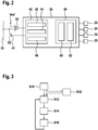
- Fig. 2 shows a field device 26.
- the field device 26 is set up to output sensor signals generated by one or more sensors 28 and / or to receive control signals to be implemented by one or more actuators.
- the field device 26 itself can have one or more sensors 28 and / or one or more actuators, for example.
- the field device 26 can output the sensor signals generated by the sensor via the serial bus 36 to other field devices 26 and in particular to the central control unit 22 or the monitoring unit 38 or control signals received via this bus 36 from other devices, in particular the central control unit 22 to an actuator so that it can implement the control instructions contained therein.
- a field device 26 can serve as a node that can receive sensor signals from an external sensor and / or from another field device 26, for example, and can then output them to other devices or that can receive control signals from other devices and then send them to one external actuator so that it converts the control signals.
- the field device 26 can include a synchronization module 40, which in turn can be subdivided into a transmission / reception module 42, a transmission position determination module 44 and a collision detection module 46.
- the functions of modules 42, 44, 46 are related to the following Fig. 3 described in more detail.
- the synchronization module 40 can be implemented as a CPLD (complex programmable logic device) in order to implement the functions at high speed.
- the field device can further comprise a microcontroller 48, which can comprise its own transmitting / receiving module 50 and a CPU 52 (central processing unit).
- the transmitting / receiving module 50 and / or the transmitting / receiving module 42 can be designed as a UART (universal asynchronous receiver transmitter).
- the serial bus 36 from the transceiver module 42 can be connected to ground (0 V) by means of a transistor 51 in order to send the bit “0” on the bus 36. If the bus 36 is not grounded by one of the bus users, then the bit "1" is sent.
- the current value of the bus is also supplied to the transmitting / receiving module 42 in the form of a signal which originates from a comparator 53 which compares the voltage on the bus 36 with a reference signal Vref.
- sending on the serial bus 36 means that the respective bus subscriber (such as the monitoring unit 38 or a field device 26) sets bits “0” and “1” on the bus 36, as just described. Conversely, “receiving” means that the respective bus participant evaluates these bits with the comparator.
- the monitoring unit 38 can be connected analogously to the serial bus 36 and / or also have a transmission / reception module 50 (for example a UART).
- a transmission / reception module 50 for example a UART
- FIG. 8 shows a flowchart for a method for checking the status of the field devices 26 of the building-bound passenger transport system 10, which can be carried out by the communication system 34 and in particular by the monitoring unit 38 and the field devices 26.
- the monitoring unit 38 determines the safety-relevant field devices 26 connected to the bus 36.
- the field devices and their bus addresses can be stored in the monitoring unit 38 in a table of bus nodes, for example. It is also possible for field devices 26 to log on to the bus 36 or to the monitoring unit 38 via the bus 36.
- the monitoring unit 38 also forms groups of field devices 26 which are each to be addressed simultaneously with a status telegram 54, as is the case, for example, in FIG Fig. 4 is shown. In the following steps S12 to S16, a status telegram 54 is then generated and evaluated for each of the groups in one cycle.
- step S12 the monitoring unit 38 sends a command block 56 of the status telegram 54 via the serial bus 36 to the field devices 26 connected to the serial bus 36, which command block relates to a group of field devices 26 according to the cycle.
- the status telegram 54 shown is divided into a command block 56 and a data block 66.
- the command block 56 is in turn divided in this order into a command value 58, a length value 60 and two address values 62, 64.
- Other telegrams that are sent via the bus 36 can also have this structure.
- these telegrams can also have a checksum.
- the beginning of the command block 56 encodes a command value 58 which identifies the beginning of a status telegram 54.
- the command value 58 can be 4 bits long.
- a status telegram 54 is identified by two different command values 58, such as the binary numbers 0011 and 1100.
- the different command values can indicate that the remaining bits of the status telegram 54 for the second command value 58 (such as 1100) and / or whose data block 66 are inverted with respect to the bits of a corresponding status telegram 54 with the first command value 58 (such as 0011) or whose data block 66 has the same content.
- the monitoring unit 38 can alternately send status telegrams with the first command value 58 and the second command value 58.
- the status telegram 54 can encode a length value 60 or a telegram length 60.
- This length value can, for example, be the next 4 bits of the status telegram 54 and / or indicate how long the status telegram 54 is (in bytes).
- the remainder of the command block 56 can be formed by two address values 62, 64.
- the address values can each have the length of one byte, i.e. 8 bits.
- the address values 62, 64 can encode a source address of the telegram and a destination address, as can be the case with all telegrams, for example.
- the address values 62, 64 can also encode the groups of field devices 26 that are to be addressed by the status telegram 54.
- the address value 62 can indicate a first addressed field device 26 and the address value 64 a last addressed field device 26 of an address interval.
- the target address 64 specifies the first addressed field device 26.
- the number of field devices 26 addressed by this status message 54 then results from the length value 60.
- the data block 66 can contain a maximum of 12 useful bytes.
- step S14 all field devices 26 receive the command block 56 of the status telegram 54 and evaluate it with the synchronization module 40.
- the command block 56 is received and decoded by the transceiver module 42.
- the elements 60, 62, 64 are forwarded to the transmission position determination module 44.
- Telegrams with a different content are forwarded from the send / receive module 42 to the send / receive module 50.
- the transmission position determination module 44 of a field device 26 determines that the field device is being addressed by the status telegram 54, it determines a status transmission position in the data block 66.
- the data block 66 can be divided into status words 68 of the same bit length (such as 8 bits, ie one byte), which are assigned to the addressed field devices 26.
- a status word can also contain start and stop bits.
- the status transmission position can then be determined, for example, by subtracting the address of the field device 26, which can be stored in the synchronization module 40, from the first target address (which can be stored in the address value 64). is the result is greater than or equal to 0 and less than the length of the data block 66, the result is the status transmission position.
- the transmission position determination module 44 then waits until the transmission position in the telegram has been reached.
- the time difference to the end of the command block 56 can be determined by multiplying the time unit for a bit by the bit length of a status word 68 and by the send position.
- the transmission position determination module 44 instructs the transmission / reception module 42 to send a status value of the field device 26 to the monitoring unit 38 via the serial bus 36.
- the status value can encode the status of the field device 26 itself or the status of one or more of the safety sensors 28 that are connected to the corresponding field device 26.
- the status value can be stored in the synchronization module 40 and / or can be updated regularly by the microcontroller 48.
- An extended 8.4 Hamming code can be used for each status word 68.
- 4 useful bits can be mapped to 7-bit code words using the 7.4 Hamming code generator matrix and an additional parity bit can be added to achieve a minimum Hamming distance of 4 (see, for example, https: //en.wikipedia. org / wiki / Hamming7,4).
- the status value can then be XORed with the address of the field device 26 that sends the status value.
- the monitoring unit 38 can thus check whether the status value comes from the expected field device 26, in which the expected address is applied to the status value by means of an XOR operation and a valid Hamming code is produced.
- the coding of the status value which is sent in the status word 68 can be carried out by the synchronization module 40 or already by the microcontroller 48.
- step S16 the monitoring unit 38 receives the data block 66 supplemented by the addressed field devices 26 and evaluates the status values.
- the monitoring unit 38 can determine the bits of the data block 66 of a status telegram 54 by forming the majority of bit values from several status telegrams 54 addressing the same field devices 26.
- the data blocks 66 of successive status telegrams 54 which relate to the same group of field devices 26 can be combined by forming a majority.
- the majority formation is field device-specific, i.e. that the last received status words that are assigned to a field device 26 are combined in this way.
- the majority formation of bits of the data block 66 and / or a status word 68 can only take place if at least one status word 68, which was coded with an error-indicating coding, indicates an incorrect coding.
- the time window of observation can be three cycles long, for example.
- the validity of the information can be evaluated for each status word 68, that is, for each field device 26. First, the error correction of the 8.4 Hamming code can be applied to each of the most recently received status words 68. The most recent valid status word 68 can then be trusted. If none of the considered status words 68 from a field device 26 is valid, a substitute status word is formed from the last three status words 68 via a bit-wise majority. If this is also invalid, a faulty state of the field device 26 or of the communication connection can be assumed.
- the status value is determined and a check is carried out to determine whether the corresponding field device 26 is reporting a safety-relevant problem.
- an alarm is generated by the monitoring unit 38.
- the alarm can be reported to the central controller 22, which then stops the operation of the system 10, for example.
- step S16 the monitoring unit 38 can send the next status telegram 54 of a cycle. It should be understood that steps S12 and S16 can also be carried out at least partially in parallel with the appropriate hardware.
- Fig. 5 shows a scheme for an interrogation cycle 70 with which all field devices 26 connected to the bus 36 can be interrogated once by means of a plurality of status telegrams 54.
- the field devices 26 are divided into groups, each of which is addressed by a status telegram 54 from cycle 70.
- the query cycles 70 can be sent regularly.
- An interrogation cycle 70 is shown, with which approximately 200 field devices 26 can be addressed in a cycle time of approximately 180 ms.
- 17 status telegrams are sent in the query cycle 70, each of which can address 12 field devices 26.
- Each of the status telegrams 54 can have a length of approximately 9 ms.
- a waiting period 72 is provided between the status telegrams 54, which can be approximately 1.5 ms.
- the waiting periods can be used by the field devices 26 or other bus users to send their own telegrams.
- a spontaneous telegram 74 is shown as an example.
- the monitoring unit can only wait for spontaneous telegrams 74 between the status telegrams. At the end of an interrogation cycle 70, a longer waiting period 74 can be provided for normally prioritized telegrams.
- step S18 a field device 26, when it detects a change in status of a connected safety sensor 28, can begin to send a spontaneous telegram 74 to the monitoring unit 38 within a waiting period 72 which encodes the change in status.
- a spontaneous telegram 74 can then be decoded immediately by the monitoring unit 38. If a spontaneous telegram 74 is sent, the monitoring unit 38 can interrupt the execution of the query cycle 70.
- the monitoring unit 38 confirms the receipt of the spontaneous telegram 74 with a further telegram to the sender of the spontaneous telegram 74. Incorrect reception can also be reported by sending a corresponding telegram to the sender of the spontaneous telegram 74. If the sender of the spontaneous telegram 74 does not receive a confirmation telegram or a telegram about an incorrect reception, the sender can repeat the sending of the spontaneous telegram 74 in the next waiting period 72.
- the collision detection module 46 of each field device 26 monitors the bus 36.
- the collision detection module 46 can monitor the bus at a sample rate that is significantly greater than the frequency of the bit values. For example, this sample rate can be at least a factor of 10 greater than the bit frequency.
- the collision detection module 46 If the collision detection module 46 sees that the bus 36 is already occupied before an intended transmission begins, it can prevent transmission. In this case, collisions can be completely avoided.
- a collision can be detected by the field device 26, which sets the bus signal to "1", but sees "0" instead on the receiving side, i.e. after the comparator 53.
- the field device 26 that has recognized the collision breaks off its transmission and the bit of the other field device 26 is correctly transmitted.
Landscapes
- Engineering & Computer Science (AREA)
- Automation & Control Theory (AREA)
- Computer Networks & Wireless Communication (AREA)
- Signal Processing (AREA)
- Indicating And Signalling Devices For Elevators (AREA)
- Arrangements For Transmission Of Measured Signals (AREA)
Description
- Die vorliegende Erfindung betrifft ein Verfahren zur Statusüberprüfung von Feldgeräten einer gebäudegebundenen Personenbeförderungsanlage, sowie ein Kommunikationssystem, das dieses Verfahren durchführt.
- Gebäudegebundene Personenbeförderungsanlagen, wie etwa Aufzüge, Fahrtreppen und Fahrsteige, dienen zum Befördern von Personen innerhalb von Gebäuden. Aufzuganlagen dienen beispielsweise dazu, Personen innerhalb eines Gebäudes zwischen verschiedenen Stockwerken befördern zu können. Hierzu kann im Regelfall eine Aufzugskabine innerhalb eines meist vertikalen Aufzugschachts verlagert werden. Wenn die Aufzugskabine ein gewünschtes Stockwerk erreicht hat, kann eine Aufzugtür und gegebenenfalls mit ihr eine zugehörige Stockwerktür geöffnet werden, um Personen einen Zutritt zu der Aufzugskabine bzw. ein Verlassen der Aufzugskabine zu ermöglichen.
- Funktionen der Aufzuganlage, wie beispielsweise ein Betätigen ihres die Aufzugskabine verlagernden Antriebs, werden meist von einer zentralen Steuereinheit gesteuert. Die zentrale Steuereinheit kann dabei beispielsweise Informationen berücksichtigen, die sie durch Verarbeiten von Sensorsignalen erhalten kann. Die Sensorsignale können insbesondere von Geräten, wie zum Beispiel Türschaltern oder anderen Sicherheitsschaltern, stammen, welche in dem die Aufzuganlage aufnehmenden Gebäude verteilt angeordnet sind. Solche Geräte werden hierin nachfolgend als Feldgeräte bezeichnet.
- Die Steuereinheit kann insbesondere Sicherheitsfunktionen ausführen, die, wenn einer der Sensoren eine sicherheitsrelevante Statusmeldung abgibt, einen Alarm erzeugen, der beispielsweise andere Funktionen der Steuereinheit blockiert. Beispielsweise kann der Antrieb der Steuereinheit nicht mehr aktiviert werden, wenn ein Türsensor meldet, dass eine Aufzugtür nicht geschlossen ist. Die entsprechenden Komponenten der Steuereinheit können als Überwachungsmodul bzw. die Steuereinheit als Überwachungseinheit aufgefasst werden.
- Die Feldgeräte und die zentrale Steuereinheit sind in der Regel über einen Datenbus verbunden, über den diese Statusmeldungen ausgetauscht werden können.
- Die
EP 2 251 293 A1 beschreibt beispielsweise eine herkömmliche Aufzugsteuervorrichtung mit einer Feldbus-Schnittstelle. - Auch die
US 2003/111300 A1 offenbart ein Verfahren und ein Kommunikationssystem nach dem Stand der Technik. - Eine Kodierung von Datenwerten mit der speziellen Hamming-Kodierung (7,4) ist beispielsweise in "https://en.wikipedia.org/wiki/Hamming(7,4)" beschrieben.
- Da Statusmeldungen der Feldgeräte beispielsweise über sicherheitsrelevante Sensordaten möglichst zeitnah von einer Überwachungseinheit ausgewertet werden sollten, kann der Bedarf bestehen, diese Statusmeldungen möglichst schnell und fehlerfrei von den Feldgeräten zu der Überwachungseinheit zu übertragen.
- Einem solchen Bedarf kann mit einer Aufzuganlage gemäss den unabhängigen Patentansprüchen entsprochen werden. Vorteilhafte Ausführungsformen sind in den abhängigen Patentansprüchen sowie der nachfolgenden Beschreibung dargelegt.
- Ein Aspekt der Erfindung betrifft ein Verfahren zur Statusüberprüfung von Feldgeräten einer gebäudegebundenen Personenbeförderungsanlage. Die Feldgeräte sind meist mit Sicherheitssensoren verbunden. Unter dem Status eines Feldgeräts soll zum einen verstanden der Status des Feldgeräts selbst verstanden werden, also ob das Feldgerät funktionsbereit ist oder nicht. Zum anderen soll darunter aber auch der Status von an dem Feldgerät angeschlossenen Sicherheitssensoren verstanden werden, also beispielsweise ob ein Sicherheitsschalter offen oder geschlossen ist. Wie bereits gesagt, kann eine gebäudegebundene Personenbeförderungsanlage eine Aufzuganlage, eine Fahrtreppenanlage oder eine Fahrsteiganlage sein. Sicherheitssensoren können im Allgemeinen alle Arten von Sensoren sein, die sicherheitsrelevante Informationen über Komponenten der gebäudegebundenen Personenbeförderungsanlage detektieren. Beispiele für derartige Sensoren sind Türschliesssensoren, die detektieren, ob eine Aufzugtür ordnungsgemäss geschlossen ist.
- Das Verfahren kann beispielsweise von einer Überwachungseinheit der gebäudegebundenen Personenbeförderungsanlage zusammen mit verschiedenen Feldgeräten automatisch durchgeführt werden, die miteinander mit einem Datenbus verbunden sind.
- Gemäss einer Ausführungsform der Erfindung umfasst das Verfahren: Senden eines Befehlsblocks eines Statustelegramms von einer Überwachungseinheit über einen seriellen Bus an eine Mehrzahl von Feldgeräten; Ergänzen eines Datenblocks des genannten Statustelegramms durch Feldgeräte, die von dem Befehlsblock angesprochen werden, mit Statuswerten; Empfangen des ergänzten Datenblocks durch die Überwachungseinheit; und Auswerten der Statuswerte durch die Überwachungseinheit. Die genannten Feldgeräte ergänzen dabei den Datenblock des einen einzigen Statustelegramms, das von der Überwachungseinheit bei einer einzelnen Statusprüfung, also zu einem bestimmten Zeitpunkt gesendet wird.
- Ein Telegramm kann als eine Bitfolge definierter Struktur angesehen werden, die über den seriellen Bus innerhalb eines geschlossenen Zeitfensters versendet wird. Für jedes Bit kann dabei die gleiche Zeiteinheit vorgesehen sein. Der Befehlsblock kann eine vorbestimmte Anzahl an Bits am Anfang des Statustelegramms sein. Der Datenblock können die verbleibenden Bits sein.
- Jedes der seriell, also hintereinander in einer Reihe angeordneten Feldgeräte kann einen Statuswert, beispielsweise eine Zahl, dadurch erzeugen, dass es an es angeschlossene Sensoren abfragt und deren Messergebnisse bewertet. Beispielsweise können an ein Feldgerät mehrere Sensoren angeschlossen sein, für die jeweils ein sensorspezifischer Statuswert, wie etwa "OK" oder "Alarm", generiert wird. Derartige Sensoren können beispielsweise Türschalter und/oder Sicherheitsschalter sein. Die sensorspezifischen Statuswerte können zu dem feldgerätspezifischen Statuswert zusammengefasst werden. Der Statuswert kann unabhängig vom Eintreffen des Statustelegrams vom Feldgerät erzeugt werden und/oder darin gespeichert werden. Beispielsweise kann ein Statuswert 4 Bits umfassen, die jeweils auf 1 gesetzt werden, wenn der entsprechende Sicherheitssensor eine Gefahr meldet (wie etwa Tür offen).
- Im einfachsten Fall kann der Statuswert auch nur anzeigen, ob das jeweilige Feldgerät noch funktionstüchtig ist. In diesem Fall kann es beispielsweise einen festen Statuswert senden. Es ist auch möglich, dass sich der die Funktionstüchtigkeit anzeigende Statuswert nach einer vorgegebenen Regel ändert, beispielsweise der Statuswert bei jeder Abfrage um 1 erhöht.
- Wenn nun die Überwachungseinheit beginnt, das Statustelegramm zu versenden, und die an den seriellen Bus angeschlossenen Feldgeräte den Befehlsblock ausgewertet haben, können diese bestimmen, ob sie dazu aufgefordert werden, ihren Statuswert an die Überwachungseinheit zu ermitteln. Welche Feldgeräte angesprochen sind, kann in dem Befehlsblock kodiert sein. Es kann aber auch sein, dass, beispielsweise bei einer entsprechend geringen Anzahl von Feldgeräten, jedes Feldgerät angesprochen ist, wenn der Befehlsblock eines Statustelegramms empfangen wird.
- Jedem der angesprochenen Feldgeräte ist eine Position im Datenblock zugewiesen und zu dem Zeitpunkt, wenn diese Position im Datenblock auf dem seriellen Bus moduliert werden soll, wird dies durch das entsprechende Feldgerät durchgeführt. Die Feldgeräte modulieren bei einer einzelnen Statusprüfung also alle nacheinander dasselbe Statustelegramm. Die Überwachungseinheit und die einzelnen Feldgeräte senden damit quasi gleichzeitig. Der von den angesprochenen Feldgeräten erzeugte Datenblock kann dann sofort von der Überwachungseinheit gelesen und ausgewertet werden.
- Da die Feldgeräte nicht abwarten, dass das Statustelegramm als reines Befehlstelegramm komplett versendet wird und anschliessend ihre Statuswerte nicht in weiteren Antworttelegrammen versenden, kann das Abfragen der Statuswerte erheblich beschleunigt werden. Es muss lediglich ein einziges Statustelegramm, das von der Überwachungseinheit initiiert wird, von den angesprochenen Feldgeräten komplettiert werden. Der Datenblock des Statustelegramms kann zeitnah von der Überwachungseinheit ausgewertet werden, ohne dass von den Feldgeräten neue Telegramme initiiert werden müssen. Die Statusinformationen von den Feldgeräten können bitsynchron in ein einziges Statustelegramm eingebunden werden, das von allen Busteilnehmern, d.h. Feldgeräte und Überwachungseinheit, gleichzeitig gelesen und empfangen werden kann.
- Der Datenblock kann nun von den Feldgeräten dadurch ergänzt werden, dass jedes an den seriellen Bus angeschlossene Feldgerät (falls es überhaupt dazu ausgeführt ist, einen sicherheitsrelevanten Statuswert zu erzeugen) die folgenden Schritte durchführt: Empfangen des Befehlsblocks durch ein Feldgerät; Bestimmen einer Statussendeposition in einem an den Befehlsblock anschliessenden Datenblock des Statustelegramms durch ein angesprochenes Feldgerät; und Senden eines Statuswerts des angesprochenen Feldgeräts über den seriellen Bus an die Überwachungseinheit, wenn die Statussendeposition in dem Datenblock erreicht ist, wobei der Statuswert den Status eines oder mehrerer Sicherheitssensoren kodiert, die an das Feldgerät angeschlossen sind. Jedem vom Befehlsblock angesprochenen Feldgerät sind dabei eine individuelle Statussendeposition und Statussendeposition zugeordnet, welche einen dem jeweiligen Feldgerät zugeordneten Bereich im Datenblock des Statustelegramms definieren. Die Statussendeposition und Statussendeposition sind dabei so festgelegt, dass sich die einzelnen Bereiche der Feldgeräte nicht überlappen.
- Datenpakete bzw. Telegramme können über den seriellen Bus dadurch versendet werden, dass in zeitlicher Abfolge einzelne Bits des Telegramms über den Bus versendet werden. Für den Bitwert 0 kann der Bus beispielsweise mit dem Grund verbunden werden, was zu einer Spannung von 0 V auf dem Leiter des Busses führt. Ein Bitwert von 1 kann durch einen offenen (nicht auf Grund gesetzten) Bus mit beispielsweise 24 V versendet werden. Die Überwachungseinheit sendet im Datenblock immer den Bitwert 1, der von einem angesprochenen Feldgerät an der ihm vorgesehenen Positionen moduliert, also in den Bitwert 0 geändert werden kann. Die Zeiteinheit, während der ein Bit versendet wird, kann konstant sein. Die Bits können insbesondere in so genannten Rahmen mit einem Start- und Stopbit versendet werden. Damit kann berechnet werden, wann ein bestimmtes Bit eines Telegramms über den Bus versendet wird, nämlich der Startzeitpunkt des Telegramms plus der Nummer des Bits im Telegramm multipliziert mit der Länge der Zeiteinheit.
- Die Position im Datenblock, an der ein Feldgerät seinen Statuswert zu senden beginnt, kann festgelegt sein, oder kann aufgrund des Befehlsblocks ermittelt werden. Beispielsweise umfasst der Datenblock eine Mehrzahl von gleich langen Statusworten, in die jeweils ein Statuswert kodiert wird. Die Statussendeposition kann durch Multiplizieren der Nummer des Feldgeräts im Datenblock mit der Länge eines Statusworts ermittelt werden.
- Gemäss einer Ausführungsform der Erfindung kodiert der Befehlsblock einen Befehlswert, der den Beginn eines Statustelegramms kennzeichnet. Der Befehlswert kann eine Bitfolge festgelegter Länge am Anfang jedes Telegrams sein. Beispielsweise können andere Befehlswerte andere Typen von Telegrammen kennzeichnen, wie etwa Steuerungsbefehle für die Feldgeräte, die nicht nur Sensoren, sondern auch Aktoren ansteuern können.
- Gemäss einer Ausführungsform der Erfindung sind Statustelegramme durch zwei verschiedene Befehlswerte gekennzeichnet. Es ist möglich, dass verschiedene Typen von Statustelegrammen vorhanden sind, die beispielsweise unterschiedlich kodiert sein können.
- Gemäss einer Ausführungsform der Erfindung sind die verbleibenden Bits eines Statustelegramms mit einem ersten Befehlswert und/oder dessen Datenblock gegenüber den Bits eines entsprechenden Statustelegramms mit einem zweiten Befehlswert bzw. dessen Datenblock gleichen Inhalts invertiert. Es können zwei Typen Statustelegramme vorhanden sein, bei denen die Datenbits bzw. bestimmte Teile des Statustelegramms gegenüber einander invertiert sind.
- Ein Befehlswert kann beispielsweise 4 Bit umfassen. Die beiden Typen von Statustelegrammen können beispielsweise die Befehlswerte aufweisen, die durch die Bitfolgen, die die Zahlen 3 (d.h. die Bitfolge 0011) und 12 (d.h. die Bitfolge 1100) repräsentieren, kodiert werden. Auch die Bitfolge des einen Befehlswerts kann gegenüber dem anderen Befehlswert invertiert sein.
- Gemäss einer Ausführungsform der Erfindung kodiert der Befehlsblock Zieladressen für Feldgeräte, die bestimmen, welche Feldgeräte durch das Statustelegramm angesprochen sind. Jedes Feldgerät kann eine bezüglich des Busses eindeutige Adresse aufweisen, beispielsweise eine Zahl, die durch vier Bit oder durch ein Byte kodiert werden kann. Beispielsweise können die Zieladressen eines Statustelegramms durch zwei Zahlen kodiert werden, die den Beginn und das Ende eines Intervalls von Feldgerätadressen darstellen. Es ist auch möglich, dass lediglich der Beginn eines Intervalls von Zieladressen in dem Befehlsblock vorhanden ist und das Intervall aufgrund einer vorgegebenen Länge des Intervalls und/oder des Statustelegramms bestimmt wird.
- Es ist aber auch möglich, dass alle an den Bus angeschlossenen Feldgeräte durch das Statustelegramm angesprochen werden, beispielsweise alleine über den Befehlswert. Zieladressen sind dann nicht notwendig und/oder der Befehlsblock muss keine Zieladressen kodieren.
- Gemäss einer Ausführungsform der Erfindung kodiert der Befehlsblock eine Telegrammlänge. Die Telegrammlänge kann die Länge des Telegramms in Bit, Byte oder eine Anzahl von Datenwerten im Datenblock kodieren. Alternativ kann ein Intervall von Zieladressen durch die Adresse eines ersten Feldgeräts und eine Anzahl auf dieses Feldgerät im Adressraum nachfolgender Feldgeräte bestimmt werden. Diese Anzahl kann aus der Telegrammlänge bestimmt werden. Es ist möglich, dass Statustelegramme unterschiedliche Längen aufweisen können.
- Gemäss einer Ausführungsform der Erfindung ist der Datenblock in Statusworte gleicher Bitlänge unterteilt, die den angesprochenen Feldgeräten zugeordnet sind und in die der Statuswert des zugeordneten Feldgeräts kodiert wird. Die Statussendeposition kann der Beginn des dem Feldgerät zugeordneten Statusworts sein. In den Statusworten sind die Statuswerte kodiert, entweder direkt als Zahlen im Binärformat und/oder auch mittels einer Kodierung, die eine fehlerhafte Übertragung über den seriellen Bus erkennen und/oder beseitigen kann. Beispielsweise kann ein Statuswort auch ein oder mehrere Paritätsbits enthalten. Jedes Statuswort kann beispielsweise ein Byte des Datenblocks sein.
- Gemäss einer Ausführungsform der Erfindung umfasst das Verfahren weiter: Erzeugen eines Alarms, wenn die durch die Überwachungseinheit empfangenen Statuswerte auf eine Gefahr hindeuten, die durch mit den Feldgeräten verbundene Sicherheitssensoren detektiert wird. Beispielsweise kann ein beliebiger Statuswert ungleich 0 auf ein Sicherheitsproblem hinweisen (wie etwa "Tür offen"). In diesem Fall kann die Überwachungseinheit weitere Komponenten der gebäudegebundenen Personenbeförderungsanlage stoppen bzw. diese davon abhalten, den Betrieb aufzunehmen.
- Gemäss einer Ausführungsform der Erfindung werden die Statuswerte mit einer fehleranzeigenden und/oder fehlerkorrigierenden Kodierung kodiert. Auf diese Weise kann die Überwachungseinheit erkennen, ob die Statuswerte korrekt über den seriellen Bus übertragen wurden. Auf einen Austausch von Bestätigungstelegrammen kann verzichtet werden. Weiter kann eine Anzahl fehlerhaft übertragener Werte durch eine Fehlerkorrektur vermindert werden.
- Beispielsweise können die Statuswerte mit einer Hamming-Kodierung kodiert werden. Beispielsweise kann der Statuswert vier Bits an Information enthalten, die wiederum über die (7,4)-Hamming-Code-Generatormatrix auf sieben Bit abgebildet werden. Die sieben Bit Codeworte können noch um ein zusätzliches Paritätsbit erweitert werden, um eine minimale Hammingdistanz von 4 zu erreichen. Für eine detaillierte Beschreibung des (7,4)-Hamming-Codes siehe beispielsweise https://en.wikipedia.org/wiki/Hamming(7,4).
- Gemäss einer Ausführungsform der Erfindung umfasst das Verfahren weiter: Erzeugen eines Alarms, wenn die durch die Überwachungseinheit empfangenen und dekodierten Statuswerte auf eine fehlerhafte Kodierung durch das sendende Feldgerät hindeuten. Neben einem Alarm aufgrund eines detektierten Sicherheitsproblems kann auch ein Alarm aufgrund eines möglicherweise fehlerhaften Sicherheitssystems erzeugt werden. Auch im Falle solch eines Alarms kann die Überwachungseinheit weitere Komponenten der gebäudegebundenen Personenbeförderungsanlage stoppen bzw. diese davon abhalten, den Betrieb aufzunehmen.
- Gemäss einer Ausführungsform der Erfindung werden alle mit dem Bus verbundenen Feldgeräte mit einer Mehrzahl von Statustelegrammen angesprochen, die regelmässig in einem Zyklus versendet werden. In der Regel können die Statuswerte von der Überwachungseinheit regelmässig abgefragt werden. Wenn beispielsweise aufgrund der Anzahl der Feldgeräte nötig ist, dass mehr als ein Statustelegramm zur Abfrage verwendet werden muss, können die Abfragen zyklisch erfolgen.
- Beispielsweise können die Feldgeräte in Gruppen eingeteilt sein, die von jeweils einem Statustelegramm aus dem Zyklus angesprochen werden. In jedem Zyklus können alle Gruppen von Feldgeräten abgefragt werden. Jede dieser Gruppen kann die gleiche Anzahl an Feldgeräten umfassen. Ein Statustelegramm kann in etwa 15 Feldgeräte gleichzeitig ansprechen. Die Anzahl der Feldgeräte kann durch die Länge des Datenblocks des Statustelegramms beschränkt sein.
- Gemäss einer Ausführungsform der Erfindung werden Statustelegramme regelmässig erzeugt bzw. nach gleichen Zeitintervallen erzeugt. Auf diese Weise kann die gleiche Statusinformation immer wieder abgefragt werden. Wenn mehrere Statustelegramme vorhanden sind, die von den gleichen Feldgeräten ergänzt wurden, kann die Überwachungseinheit die Bits des Datenblocks eines Statustelegramms mittels einer Majoritätsbildung von Bitwerten von mehreren, die gleichen Feldgeräte ansprechenden Statustelegrammen ermitteln. Majoritätsbildung bedeutet, dass ein Bit auf den Wert gesetzt wird, der an der gleichen Position in den zu betrachtenden Statustelegrammen am häufigsten vorkommt. Beispielsweise kann der eigentliche Bitwert das Bit sein, das bei drei Zyklen an der betreffenden Position mindestens zweimal vorkommt.
- Gemäss einer Ausführungsform der Erfindung erfolgt die Majoritätsbildung von Bits des Datenblocks und/oder eines Statusworts nur, wenn wenigstens ein Statuswort, das mit einer fehleranzeigenden Kodierung kodiert wurde, eine fehlerhafte Kodierung anzeigt. Ein fehlerfreier Datenblock bzw. Statuswort kann direkt ohne Majoritätsbildung weiterverarbeitet werden.
- Gemäss einer Ausführungsform der Erfindung belegen Statustelegramme den Bus mit zeitlichem Abstand und sind zwischen den Statustelegrammen Karenzzeiten vorgesehen. Der Bus muss nicht vollständig mit Statustelegrammen belegt sein, sondern es können Zeiträume vorhanden sein, in denen andere Busteilnehmer als die Überwachungseinheit Telegramme versenden können. Beispielsweise kann ein Zyklus von Statustelegrammen, der mehrere Gruppen von Feldgeräten abfragt, aus Statustelegrammen gebildet sein, zwischen denen Karenzzeiten vorhanden sind.
- Gemäss einer Ausführungsform der Erfindung beginnt ein Feldgerät, wenn es eine Statusänderung eines angeschlossenen Sicherheitssensors erfasst, innerhalb einer Karenzzeit ein Spontantelegramm an die Überwachungseinheit zu senden, das die Statusänderung kodiert. Ein Beispiel für Telegramme, die von den Feldgeräten selbstständig gesendet werden können, sind Spontantelegramme, die unabhängig von einer Aufforderung durch die Überwachungseinheit an diese gesendet werden. Auf diese Weise kann ein Feldgerät ein Sicherheitsproblem melden, obwohl es im Zyklus erst später abgefragt werden würde.
- Von anderen Busteilnehmern versendete Telegramme und insbesondere Spontantelegramme können länger sein als die Karenzzeiten. In diesem Fall kann die Überwachungseinheit den Abfragezyklus so lange unterbrechen bzw. aufschieben, bis das Telegramm vollständig versendet wurde.
- Ein weiterer Aspekt der Erfindung betrifft ein Kommunikationssystem für eine gebäudegebundene Personenbeförderungsanlage, das eine Mehrzahl von Feldgeräten aufweist; eine Überwachungseinheit; und einen seriellen Bus, mit dem die Überwachungseinheit und die Mehrzahl von Feldgeräten verbunden sind. Die Überwachungseinheit kann beispielsweise eine zentrale Steuerung oder ein Modul einer zentralen Steuerung der gebäudegebundenen Personenbeförderungsanlage sein. Das Kommunikationssystem ist weiter dazu ausgeführt, das Verfahren, so wie es obenstehend und unterstehend beschrieben ist, durchzuführen.
- Gemäss einer Ausführungsform der Erfindung umfasst jedes der Feldgeräte ein Synchronisationsmodul. Das Synchronisationsmodul ist zum Empfangen des Befehlsblocks und zum Senden des entsprechenden Statusworts eines Statustelegramms ausgeführt. Weiter kann das Feldgerät weitere Komponenten umfassen, die beispielsweise mit Sensoren kommunizieren, Sensordaten verarbeiten und/oder andere Telegramme erzeugen und/oder verarbeiten können. Das Synchronisationsmodul kann beispielsweise in der Form eines CPLDs (complex programmable logic device) implementiert sein, während weitere Funktionen des Feldgeräts von einem Mikrocontroller ausgeführt werden können.
- Das Synchronisationsmodul kann ein Sende-/Empfangsmodul zum Senden und Empfangen von Bitfolgen über den Bus aufweisen, wobei das Sende-/Empfangsmodul dazu ausgeführt ist, Befehlsblöcke eines Statustelegramms zu erkennen und Statuswerte innerhalb eines Statustelegramms zu versenden.
- Weiter kann das Synchronisationsmodul ein Sendepositionsbestimmungsmodul aufweisen, das dazu ausgeführt ist, die Statussendeposition aus einem mit dem Sende-/Empfangsmodul empfangenen Befehlsblock eines Statustelegramms zu bestimmen und, wenn die Statussendeposition erreicht ist, das Sende-/Empfangsmodul zum Versenden des Statuswerts anzustossen. Der Statuswert kann dazu schon im Synchronisationsmodul gespeichert sein und/oder muss nicht erst von anderen Komponenten des Feldgeräts abgefragt werden.
- Weiter kann das Synchronisationsmodul ein Kollisionserfassungsmodul aufweisen, das dazu ausgeführt ist, zu erkennen, wenn ein anderes Feldgerät und/oder die Überwachungseinheit bereits auf dem Bus sendet und ein Senden des Synchronisationsmoduls in diesem Fall abzubrechen.
- Weiter kann das Synchronisationsmodul dazu ausgeführt sein, ein vom Feldgerät erzeugtes Spontantelegramm in den Bus zu senden bzw. dieses aufgrund eines Befehls vom Feldgerät selbst zu erzeugen. Es kann auch möglich sein, dass das Synchronisationsmodul während einem Statustelegramm das Versenden von Spontantelegrammen unterdrückt oder verzögert.
- Es wird darauf hingewiesen, dass einige der möglichen Merkmale und Vorteile der Erfindung hierin mit Bezug auf unterschiedliche Ausführungsformen beschrieben sind. Ein Fachmann erkennt, dass die Merkmale in geeigneter Weise kombiniert, angepasst oder ausgetauscht werden können, um zu weiteren Ausführungsformen der Erfindung zu gelangen.
- Nachfolgend werden Ausführungsformen der Erfindung unter Bezugnahme auf die beigefügten Zeichnungen beschrieben, wobei weder die Zeichnungen noch die Beschreibung als die Erfindung einschränkend auszulegen sind.
-
Fig. 1 zeigt schematisch eine gebäudegebundene Personenbeförderungsanlage in der Form einer Aufzuganlage gemäss einer Ausführungsform der Erfindung. -
Fig. 2 zeigt schematisch ein Feldgerät für eine gebäudegebundene Personenbeförderungsanlage gemäss einer Ausführungsform der Erfindung. -
Fig. 3 zeigt ein Flussdiagramm für ein Verfahren zur Statusüberprüfung von Feldgeräten einer gebäudegebundenen Personenbeförderungsanlage gemäss einer Ausführungsform der Erfindung. -
Fig. 4 zeigt das Schema eines Statustelegramms für das Verfahren aus derFig. 3 . -
Fig. 5 zeigt das Schema eines Telegrammzyklus für das Verfahren aus derFig. 3 . - Die Figuren sind lediglich schematisch und nicht massstabsgetreu. Gleiche Bezugszeichen bezeichnen in den verschiedenen Figuren gleiche oder gleichwirkende Merkmale.
-
Fig. 1 zeigt eine gebäudegebundene Personenbeförderungsanlage 10 in der Form einer Aufzuganlage 10. Im Folgenden wird beispielhaft eine Aufzuganlage beschrieben. Es ist aber zu verstehen, dass auch andere Personenbeförderungsanlagen 10, wie etwa Fahrtreppenanlagen oder Fahrsteige, solche Kommunikationssysteme, Überwachungseinheiten, Feldgeräte und Sensoren aufweisen können, wie sie im Folgenden beschrieben werden. - Die Aufzuganlage 10 umfasst einen Aufzugschacht 12, in dem eine Aufzugskabine 14 und ein Gegengewicht 16 verfahren werden können. Die Aufzugskabine 14 und das Gegengewicht 16 sind hierzu an einem seil- oder riemenartigen Tragmittel 18 gehalten, welches von einer Antriebsmaschine 20 verlagert werden kann. Der Betrieb der Aufzuganlage 10 und insbesondere die Antriebsmaschine 20 kann mithilfe einer zentralen Steuereinheit 22 gesteuert werden.
- Um eine korrekte Funktion und insbesondere eine Sicherheit der Aufzuganlage 10 gewährleisten zu können, sind in einem die Aufzuganlage 10 aufnehmenden Bauwerk 24 mehrere Feldgeräte 26 aufgenommen. Die Feldgeräte 26 sind dabei über das Bauwerk 24 hin verteilt angeordnet. Die Feldgeräte 26 können beispielsweise einen Türschalter 28 umfassen bzw. mit einem Türschalter 28 verbunden sein, welche einen Schliesszustand von Türen 30, insbesondere von Stockwerktüren, der Aufzuganlage 10 überwachen können. Die Türschalter 28 können als Sicherheitssensoren angesehen werden. Beispielsweise nahe einem Boden oder einer Grube des Aufzugschachts 12 kann ferner eine Leiter 32 gelagert sein, deren korrekt aufgeräumte Positionierung an einer Seitenwand des Aufzugschachts 12 beispielsweise mithilfe eines mit einem Feldgerät 26 verbundenen Schalter 33 überwacht wird. Der Schalter 33 kann ebenfalls als ein Sicherheitssensor angesehen werden. Die Feldgeräte 26 können Teil eines Kommunikationssystems 34 der Aufzuganlage 10 sein und beispielsweise über einen seriellen Bus 36 mit der zentralen Steuereinheit 22 bzw. insbesondere mit einer zum Beispiel dort integriert vorgesehenen Überwachungseinheit 38 verbunden sein. Die Feldgeräte 26 sind seriell hintereinander angeordnet, wobei jeweils zwei hintereinander angeordnete Feldgeräte 26 mit dem seriellen Bus 36 verbunden sind.
-
Fig. 2 zeigt ein Feldgerät 26. Das Feldgerät 26 ist dazu eingerichtet, von einem oder mehreren Sensoren 28 erzeugte Sensorsignale auszugeben und/oder von einem oder mehreren Aktoren umzusetzende Steuersignale zu empfangen. Dabei kann das Feldgerät 26 beispielsweise selbst einen oder mehrere Sensoren 28 und/oder einen oder mehrere Aktoren aufweisen. Das Feldgerät 26 kann die von dem Sensor erzeugten Sensorsignale über den seriellen Bus 36 an andere Feldgeräte 26 und insbesondere an die zentrale Steuereinheit 22 bzw. die Überwachungseinheit 38 ausgeben bzw. über diesen Bus 36 von anderen Geräten, insbesondere der zentralen Steuereinheit 22, empfangene Steuersignale an einen Aktor leiten, damit dieser die darin enthaltenen Steueranweisungen umsetzen kann. Alternativ oder zusätzlich kann ein Feldgerät 26 als Knotenpunkt dienen, der beispielsweise Sensorsignale von einem externen Sensor und/oder von einem anderen Feldgerät 26 empfangen kann und diese dann an weitere Geräte ausgeben kann bzw. der von weiteren Geräten Steuersignale empfangen kann und diese dann an einen externen Aktor weitergeben kann, damit dieser die Steuersignale umsetzt. - Die
Fig. 2 zeigt, dass das Feldgerät 26 ein Synchronisationsmodul 40 umfassen kann, das wiederum in ein Sende-/Empfangsmodul 42, ein Sendepositionsbestimmungsmodul 44 und ein Kollisionserfassungsmodul 46 unterteilt sein kann. Die Funktionen der Module 42, 44, 46 werden in Bezug auf die folgendeFig. 3 genauer beschrieben. Beispielsweise kann das Synchronisationsmodul 40 als CPLD (complex programmable logic device) implementiert sein, um die Funktionen in hoher Geschwindigkeit umzusetzen. - Das Feldgerät kann weiter einen Mikrocontroller 48 umfassen, der ein eigenes Sende-/Empfangsmodul 50 und eine CPU 52 (central processing unit) umfassen kann. Das Sende-/Empfangsmodul 50 und/oder das Sende-/Empfangsmodul 42 können als UART (universal asynchronous receiver transmitter) ausgeführt sein.
- Weiter ist in der
Fig. 2 gezeigt, dass der serielle Bus 36 von dem Sende-/Empfangsmodul 42 mittels eines Transistors 51 mit Grund (0 V) verbunden werden kann, um auf dem Bus 36 das Bit "0" zu versenden. Ist der Bus 36 nicht von einem der Busteilnehmer auf Grund gesetzt, dann wird das Bit "1" gesendet. Weiter wird dem Sende-/Empfangsmodul 42 der aktuelle Wert des Busses in der Form eines Signals zugeführt, das aus einem Komparator 53 stammt, der die Spannung auf dem Bus 36 mit einem Referenzsignal Vref vergleicht. - Es ist zu verstehen, dass ein "Senden" auf dem seriellen Bus 36 bedeutet, dass der jeweilige Busteilnehmer (wie etwa die Überwachungseinheit 38 oder ein Feldgerät 26) Bits "0" und "1" auf dem Bus 36 setzt, wie eben beschrieben. Umgekehrt bedeutet ein "Empfangen", dass der jeweilige Busteilnehmer diese Bits mit dem Komparator auswertet.
- Die Überwachungseinheit 38 kann analog an den seriellen Bus 36 angeschlossen sein und/oder auch ein Sende-/Empfangsmodul 50 (beispielsweise ein UART) aufweisen.
-
Fig. 3 zeigt ein Flussdiagramm für ein Verfahren zur Statusüberprüfung der Feldgeräte 26 der gebäudegebundenen Personenbeförderungsanlage 10, das von dem Kommunikationssystem 34 und insbesondere der Überwachungseinheit 38 und den Feldgeräten 26 durchgeführt werden kann. - Im Schritt S10 bestimmt die Überwachungseinheit 38 die an den Bus 36 angeschlossenen sicherheitsrelevanten Feldgeräte 26. Die Feldgeräte und deren Busadressen können beispielsweise in einer Tabelle von Busknoten in der Überwachungseinheit 38 gespeichert sein. Es ist auch möglich, dass sich Feldgeräte 26 am Bus 36 bzw. bei der Überwachungseinheit 38 über den Bus 36 anmelden.
- Weiter bildet die Überwachungseinheit 38 Gruppen von Feldgeräten 26, die jeweils gleichzeitig mit einem Statustelegramm 54 angesprochen werden sollen, so wie es beispielsweise in der
Fig. 4 dargestellt ist. In den folgenden Schritten S12 bis S16 wird in einem Zyklus dann für jede der Gruppen ein Statustelegramm 54 erzeugt und ausgewertet. - Im Schritt S12 sendet die Überwachungseinheit 38 über den seriellen Bus 36 einen Befehlsblock 56 des Statustelegramms 54 an die an den seriellen Bus 36 angeschlossenen Feldgeräte 26, das eine Gruppe von Feldgeräten 26 entsprechend dem Zyklus betrifft.
- Im Allgemeinen ist das in der
Fig. 4 gezeigte Statustelegramm 54 in einen Befehlsblock 56 und einen Datenblock 66 unterteilt. Der Befehlsblock 56 wiederum ist in dieser Reihenfolge wiederum in einen Befehlswert 58, einen Längenwert 60 und zwei Adresswerte 62, 64 aufgeteilt. Auch andere Telegramme, die über den Bus 36 versendet werden, können diese Struktur aufweisen. Im Gegensatz zum Statustelegramm 54 können diese Telegramme weiter eine Prüfsumme aufweisen. - Der Beginn des Befehlsblocks 56 kodiert einen Befehlswert 58, der den Beginn eines Statustelegramms 54 kennzeichnet. Beispielsweise kann der Befehlswert 58 4 Bit lang sein.
- Es ist möglich, dass ein Statustelegramm 54 durch zwei verschiedene Befehlswerte 58 gekennzeichnet wird, wie etwa die Binärzahlen 0011 und 1100. Die unterschiedlichen Befehlswerte können anzeigen, dass die verbleibenden Bits des Statustelegramms 54 für den zweiten Befehlswert 58 (wie etwa 1100) und/oder dessen Datenblock 66 gegenüber den Bits eines entsprechenden Statustelegramms 54 mit dem ersten Befehlswert 58 (wie etwa 0011) bzw. dessen Datenblock 66 gleichen Inhalts invertiert sind. Beispielsweise kann die Überwachungseinheit 38 abwechselnd Statustelegramme mit dem ersten Befehlswert 58 und dem zweiten Befehlswert 58 versenden.
- Nach dem Befehlswert 58 kann das Statustelegramm 54 ein Längenwert 60 bzw. eine Telegrammlänge 60 kodieren. Dieser Längenwert kann beispielsweise die nächsten 4 Bit des Statustelegramms 54 darstellen und/oder anzeigen, wie lang das Statustelegramm 54 (in Bytes) ist.
- Der Rest des Befehlsblocks 56 kann durch zwei Adresswerte 62, 64 gebildet sein. Die Adresswerte können jeweils die Länge eines Bytes, d.h. 8 Bit, aufweisen. Beispielsweise können die Adresswerte 62, 64 eine Quelladresse des Telegramms und eine Zieladresse kodieren, wie es etwa bei allen Telegrammen der Fall sein kann. Bei einem Statustelegramm 54 können die Adresswerte 62, 64 auch die Gruppen von Feldgeräten 26 kodieren, die durch das Statustelegramm 54 angesprochen werden sollen.
- Beispielsweise können der Adresswert 62 ein erstes angesprochenes Feldgerät 26 und der Adresswert 64 ein letztes angesprochenes Feldgerät 26 eines Adressintervalls angeben. Es ist aber auch möglich, dass die Zieladresse 64 das erste angesprochene Feldgerät 26 angibt. Aus dem Längenwert 60 ergibt sich dann die Zahl der durch dieses Statustelegramm 54 angesprochenen Feldgeräte 26. Bei einer maximalen Länge des Statustelegramms von 15 Byte kann der Datenblock 66 maximal 12 Nutzbytes enthalten.
- Im Schritt S14 empfangen alle Feldgeräte 26 den Befehlsblock 56 des Statustelegramms 54 und werten diesen mit dem Synchronisationsmodul 40 aus. Insbesondere wird der Befehlsblock 56 von dem Sende-/Empfangsmodul 42 empfangen und dekodiert. Wenn ein Befehlswert 58 für ein Statustelegramm 54 empfangen wurde, werden die Elemente 60, 62, 64 an das Sendepositionsbestimmungsmodul 44 weitergeleitet. Telegramme mit anderem Inhalt werden von dem Sende-/Empfangsmodul 42 an das Sende-/Empfangsmodul 50 weitergeleitet.
- Wenn das Sendepositionsbestimmungsmodul 44 eines Feldgeräts 26 feststellt, dass das Feldgerät durch das Statustelegramm 54 adressiert wird, bestimmt es eine Statussendeposition in dem Datenblock 66. Der Datenblock 66 kann in Statusworte 68 gleicher Bitlänge unterteilt sein (wie etwa 8 Bit, d.h. ein Byte), die den angesprochenen Feldgeräten 26 zugeordnet sind. Ein Statuswort kann zusätzlich Start- und Stopbits enthalten. Die Statussendeposition kann dann beispielsweise durch Subtrahieren der Adresse des Feldgeräts 26, die im Synchronisationsmodul 40 gespeichert sein kann, von der ersten Zieladresse (die im Adresswert 64 gespeichert sein kann) ermittelt werden. Ist das Ergebnis grösser gleich 0 und kleiner als die Länge des Datenblocks 66, ist das Ergebnis die Statussendeposition.
- Das Sendepositionsbestimmungsmodul 44 wartet anschliessend, bis die Sendeposition im Telegramm erreicht ist. Die zeitliche Differenz zum Ende des Befehlsblocks 56 kann durch Multiplizieren der Zeiteinheit für ein Bit mit der Bitlänge eines Statusworts 68 und mit der Sendeposition bestimmt werden.
- Ist die Sendeposition erreicht, weist das Sendepositionsbestimmungsmodul 44 das Sende-/Empfangsmodul 42 an, einen Statuswert des Feldgeräts 26 über den seriellen Bus 36 an die Überwachungseinheit 38 zu senden.
- Der Statuswert kann den Status des Feldgerät 26 selbst oder den Status einer oder mehrerer der Sicherheitssensoren 28 kodieren, die an das entsprechende Feldgerät 26 angeschlossen sind. Der Statuswert kann in dem Synchronisationsmodul 40 gespeichert sein und/oder kann vom Mikrocontroller 48 regelmässig aktualisiert werden.
- Für jedes Statuswort 68 kann ein erweiterter 8,4-Hamming-Code verwendet werden. Dabei können 4 Nutzbits über die 7,4-Hamming-Code-Generatormatrix auf 7-Bit-Codeworte abgebildet und noch um ein zusätzliches Paritätsbit erweitert werden, um eine minimale Hammingdistanz von 4 zu erreichen (siehe beispielsweise https://en.wikipedia.org/wiki/Hamming7,4).
- Anschliessend kann eine XOR-Operation des Statuswerts mit der Adresse des Feldgeräts 26, das den Statuswert versendet, erfolgen. Damit kann die Überwachungseinheit 38 überprüfen, ob der Statuswert vom erwarteten Feldgerät 26 stammt, in dem die erwartete Adresse mittels einer XOR-Operation auf den Statuswert angewendet wird und ein gültiger Hamming-Code entsteht.
- Das Kodieren des Statuswerts, der in dem Statuswort 68 versendet wird, kann durch das Synchronisationsmodul 40 oder bereits durch den Mikrocontroller 48 erfolgen.
- Im Schritt S16 empfängt die Überwachungseinheit 38 den durch die angesprochenen Feldgeräte 26 ergänzten Datenblock 66 und wertet die Statuswerte aus.
- Wenn die Statustelegramme 54 für eine Gruppe von Feldgeräten regelmässig erzeugt werden, kann die Überwachungseinheit 38 die Bits des Datenblocks 66 eines Statustelegramms 54 mittels einer Majoritätsbildung von Bitwerten von mehreren, die gleichen Feldgeräte 26 ansprechenden Statustelegrammen 54 ermitteln.
- Beispielsweise können die Datenblöcke 66 von aufeinanderfolgenden Statustelegrammen 54, die die gleiche Gruppe von Feldgeräten 26 betreffen, mittels Majoritätsbildung zusammengefasst werden.
- Es kann auch sein, dass die Majoritätsbildung Feldgerät-spezifisch erfolgt, d.h., dass die letzten empfangenen Statusworte, die einem Feldgerät 26 zugeordnet sind, auf diese Weise zusammengefasst werden.
- Die Majoritätsbildung von Bits des Datenblocks 66 und/oder eines Statusworts 68 kann nur dann erfolgen, wenn wenigstens ein Statuswort 68, das mit einer fehleranzeigenden Kodierung kodiert wurde, eine fehlerhafte Kodierung anzeigt.
- Das Zeitfenster der Betrachtung kann beispielsweise drei Zyklen lang sein. Die Gültigkeit der Information kann pro Statuswort 68, also pro Feldgerät 26, ausgewertet werden. Zuerst kann die Fehlerkorrektur des 8,4-Hamming-Codes auf jedes der zuletzt empfangenen Statusworte 68 angewandt werden. Dem jüngsten gültigen Statuswort 68 kann dann vertraut werden. Wenn keins der betrachteten Statusworte 68 von einem Feldgerät 26 gültig ist, wird über bitweise Majorität aus den drei letzten Statusworten 68 ein Ersatzstatuswort gebildet. Ist auch dieses ungültig, kann ein fehlerhafter Zustand des Feldgeräts 26 oder der Kommunikationsverbindung angenommen werden.
- Im Falle eines korrekten 8,4-Hamming-Codes wird der Statuswert ermittelt und überprüft, ob das entsprechende Feldgerät 26 ein sicherheitsrelevantes Problem meldet.
- In beiden Fällen, d.h., wenn die durch die Überwachungseinheit 38 empfangenen Statuswerte auf eine Gefahr hindeuten, die durch mit den Feldgeräten 26 verbundene Sicherheitssensoren 28 detektiert wird, oder wenn die durch die Überwachungseinheit 38 empfangenen und dekodierten Statuswerte auf eine fehlerhafte Kodierung hindeuten, wird durch die Überwachungseinheit 38 ein Alarm erzeugt. Der Alarm kann an die zentrale Steuerung 22 weitergemeldet werden, die dann beispielsweise den Betrieb der Anlage 10 stoppt.
- Nach dem Schritt S16 kann die Überwachungseinheit 38 das nächste Statustelegramm 54 eines Zyklus versenden. Es ist zu verstehen, dass die Schritte S12 und S16 mit entsprechender Hardware auch zumindest teilweise parallel ausgeführt werden können.
-
Fig. 5 zeigt ein Schema für einen Abfragezyklus 70, mit dem alle an den Bus 36 angeschlossenen Feldgeräte 26 einmal mittels einer Mehrzahl von Statustelegrammen 54 abgefragt werden können. Die Feldgeräte 26 sind in Gruppen eingeteilt, die von jeweils einem Statustelegramm 54 aus dem Zyklus 70 angesprochen werden. Die Abfragezyklen 70 können regelmässig versendet werden. - Gezeigt ist ein Abfragezyklus 70, mit dem etwa 200 Feldgeräte 26 in einer Zykluszeit von etwa 180 ms angesprochen werden können. Um die 200 Feldgeräte 26 ansprechen zu können, werden in dem Abfragezyklus 70 17 Statustelegramme versendet, die jeweils 12 Feldgeräte 26 ansprechen können.
- Jedes der Statustelegramme 54 kann eine Länge von etwa 9 ms aufweisen. Zwischen den Statustelegrammen 54 ist eine Karenzzeit 72 vorgesehen, die etwa 1,5 ms betragen kann. Die Karenzzeiten können von den Feldgeräten 26 oder anderen Busteilnehmern dazu verwendet werden, eigene Telegramme zu versenden. In der
Fig. 5 ist dazu beispielhaft ein Spontantelegramm 74 gezeigt. - Zwischen den Statustelegrammen kann die Überwachungseinheit lediglich auf Spontantelegramme 74 warten. Am Ende eines Abfragezyklus 70 kann eine längere Karenzzeit 74 für normal priorisierte Telegramme vorgesehen sein.
- Im Schritt S18 (siehe
Fig. 3 ) kann ein Feldgerät 26, wenn es eine Statusänderung eines angeschlossenen Sicherheitssensors 28 erfasst, innerhalb einer Karenzzeit 72 ein Spontantelegramm 74 an die Überwachungseinheit 38 zu senden beginnen, das die Statusänderung kodiert. - Ein Spontantelegramm 74 kann dann von der Überwachungseinheit 38 sofort dekodiert werden. Wird ein Spontantelegramm 74 gesendet, kann die Überwachungseinheit 38 das Durchführen des Abfragezyklus 70 unterbrechen.
- Es ist möglich, dass die Überwachungseinheit 38 mit einem weiteren Telegramm an den Versender des Spontantelegramms 74 den Empfang des Spontantelegramms 74 bestätigt. Auch ein fehlerhafter Empfang kann durch ein entsprechendes Telegramm an den Versender des Spontantelegramms 74 mitgeteilt werden. Empfängt der Versender des Spontantelegramms 74 kein Bestätigungstelegramm oder ein Telegramm über einen fehlerhaften Empfang, kann der Versender in der nächsten Karenzzeit 72 das Versenden des Spontantelegramms 74 wiederholen.
- Beispielsweise um zu verhindern, dass zwei Feldgeräte 26 gleichzeitig ein Spontantelegramm 74 versenden, überwacht das Kollisionserfassungsmodul 46 jedes Feldgeräts 26 den Bus 36. Dazu kann das Kollisionserfassungsmodul 46 den Bus mit einer Samplerate überwachen, die wesentlich grösser als die Frequenz der Bitwerte ist. Beispielsweise kann diese Samplerate um mindestens den Faktor 10 grösser sein als die Bit-Frequenz.
- Sieht das Kollisionserfassungsmodul 46, dass vor Beginn einer beabsichtigten Sendung der Bus 36 bereits belegt ist, kann es das Senden unterbinden. In diesem Fall können Kollisionen vollständig vermieden werden.
- Wurde mit dem Senden bereits begonnen, kann eine Kollision von dem Feldgerät 26 entdeckt werden, das das Bussignal auf "1" setzt, aber stattdessen "0" auf der Empfangsseite, d.h. nach dem Komparator 53, sieht. In diesem Fall bricht das Feldgerät 26, das die Kollision erkannt hat, seine Sendung ab und das Bit des anderen Feldgeräts 26 wird korrekt übertragen.
- Abschliessend ist daraufhinzuweisen, dass Begriffe wie "aufweisend", "umfassend" etc. keine anderen Elemente oder Schritte ausschliessen und Begriffe wie "eine" oder "ein" keine Vielzahl ausschliessen. Ferner sei daraufhingewiesen, dass Merkmale oder Schritte, die mit Verweis auf eines der obigen Ausführungsbeispiele beschrieben worden sind, auch in Kombination mit anderen Merkmalen oder Schritten anderer oben beschriebener Ausführungsbeispiele verwendet werden können. Bezugszeichen in den Ansprüchen sind nicht als Einschränkung anzusehen.
Claims (15)
- Verfahren zur Statusüberprüfung von Feldgeräten (26) einer gebäudegebundenen Personenbeförderungsanlage (10), das Verfahren umfassend:Senden (S10) eines Befehlsblocks (56) eines Statustelegramms (54) von einer Überwachungseinheit (38) über einen seriellen Bus (36) an eine Mehrzahl von Feldgeräten (26);Ergänzen (S12) des genannten Statustelegramms (54) durch Feldgeräte (26), die von dem genannten Befehlsblock (56) angesprochen werden, auf folgende Weise:Empfangen (S14) des genannten Befehlsblocks (56) durch ein Feldgerät (26);Bestimmen (S14) einer Statussendeposition in einem an den genannten Befehlsblock (56) anschliessenden Datenblock (66) des genannten Statustelegramms (54) durch ein angesprochenes Feldgerät (26);Senden (S14) eines Statuswerts des angesprochenen Feldgeräts (26) über den seriellen Bus (36) an die Überwachungseinheit (38), wenn die Statussendeposition in dem genannten Datenblock (66) erreicht ist, wobei der Statuswert den Status des Feldgeräts (26) kodiert;Empfangen des durch die angesprochenen Feldgeräte (26) ergänzten Datenblocks (66) durch die Überwachungseinheit (38);Auswerten (S16) der Statuswerte durch die Überwachungseinheit (38).
- Verfahren nach Anspruch 1,
wobei der Befehlsblock (56) einen Befehlswert (58) kodiert, der den Beginn eines Statustelegramms (54) kennzeichnet. - Verfahren nach Anspruch 2,wobei Statustelegramme (54) durch zwei verschiedene Befehlswerte (58) gekennzeichnet sind;wobei die verbleibenden Bits eines Statustelegramms (54) mit einem ersten Befehlswert (58) und/oder dessen Datenblock (66) gegenüber den Bits eines entsprechenden Statustelegramms (54) mit einem zweiten Befehlswert (58) bzw. dessen Datenblock (66) gleichen Inhalts invertiert sind.
- Verfahren nach einem der vorangehenden Ansprüche,
wobei der Befehlsblock (56) Zieladressen (64) für Feldgeräte (26) kodiert, die bestimmen, welche Feldgeräte (26) durch das Statustelegramm (54) angesprochen sind. - Verfahren nach einem der vorhergehenden Ansprüche,
wobei der Befehlsblock (56) eine Telegrammlänge (60) kodiert. - Verfahren nach einem der vorhergehenden Ansprüche,wobei der Datenblock (66) in Statusworte (68) gleicher Bitlänge unterteilt ist, die den angesprochenen Feldgeräten (26) zugeordnet sind und in die der Statuswert des zugeordneten Feldgeräts (26) kodiert wird;wobei die Statussendeposition der Beginn des dem Feldgerät (26) zugeordneten Statusworts (68) ist.
- Verfahren nach einem der vorangehenden Ansprüche, weiter umfassend:
Erzeugen eines Alarms, wenn die durch die Überwachungseinheit (68) empfangenen Statuswerte auf eine Gefahr hindeuten, die durch mit den Feldgeräten (26) verbundene Sicherheitssensoren (28, 33) detektiert wird. - Verfahren nach einem der vorangehenden Ansprüche,wobei die Statuswerte mit einer fehleranzeigenden und/oder fehlerkorrigierenden Kodierung kodiert werden; und/oderwobei die Statuswerte mit einer Hamming-Kodierung kodiert werden.
- Verfahren nach einem der vorangehenden Ansprüche, weiter umfassend:
Erzeugen eines Alarms, wenn die durch die Überwachungseinheit (38) empfangenen und dekodierten Statuswerte auf eine fehlerhafte Kodierung hindeuten. - Verfahren nach einem der vorangehenden Ansprüche,wobei alle mit dem Bus (36) verbundenen Feldgeräte (26) mit einer Mehrzahl von Statustelegrammen (54) angesprochen werden, die regelmässig in einem Zyklus (70) versendet werden;wobei die Feldgeräte (26) in Gruppen eingeteilt sind, die von jeweils einem Statustelegramm (54) aus dem Zyklus (70) angesprochen werden.
- Verfahren nach einem der vorhergehenden Ansprüche,wobei Statustelegramme (54) regelmässig erzeugt werden;wobei die Überwachungseinheit (38) die Bits des Datenblocks (66) eines Statustelegramms (54) mittels einer Majoritätsbildung von Bitwerten von mehreren, die gleichen Feldgeräte (26) ansprechenden Statustelegramme (54) ermittelt.
- Verfahren nach Anspruch 11,
wobei die Majoritätsbildung von Bits des Datenblocks (66) und/oder eines Statusworts (68) nur erfolgt, wenn wenigstens ein Statuswort (68), das mit einer fehleranzeigenden Kodierung kodiert wurde, eine fehlerhafte Kodierung anzeigt. - Verfahren nach einem der vorangehenden Ansprüche,wobei Statustelegramme (54) den Bus (36) mit zeitlichem Abstand belegen und zwischen den Statustelegrammen (54) Karenzzeiten (72) vorgesehen sind;wobei ein Feldgerät (26), wenn es eine Statusänderung eines angeschlossenen Sicherheitssensors (28, 33) erfasst, innerhalb einer Karenzzeit (72) ein Spontantelegramm (74) an die Überwachungseinheit (38) zu senden beginnt, das die Statusänderung kodiert.
- Kommunikationssystem (34) für eine gebäudegebundene Personenbeförderungsanlage (10), wobei das Kommunikationssystem (34) umfasst:eine Mehrzahl von Feldgeräten (26);eine Überwachungseinheit (38);einen seriellen Bus (36), mit dem die Überwachungseinheit (38) und die Mehrzahl von Feldgeräten (26) verbunden sind;wobei das Kommunikationssystem (34) dazu ausgeführt ist, das Verfahren nach einem der vorhergehenden Ansprüche durchzuführen.
- Kommunikationssystem (34) nach Anspruch 14,
wobei jedes der Feldgeräte (26) ein Synchronisationsmodul (40) umfasst, das aufweist:ein Sende-/Empfangsmodul (42) zum Senden und Empfangen von Bitfolgen über den Bus (36), wobei das Sende-/Empfangsmodul (42) dazu ausgeführt ist, Befehlsblöcke (56) eines Statustelegramms (54) zu erkennen und Statuswerte innerhalb eines Statustelegramms (54) zu versenden;ein Sendepositionsbestimmungsmodul (44), das dazu ausgeführt ist, die Statussendeposition aus einem mit dem Sende-/Empfangsmodul (42) empfangenen Befehlsblock (56) eines Statustelegramms (54) zu bestimmen und damit das Sende-/Empfangsmodul (42) zum Versenden des Statuswerts anzustossen.
Applications Claiming Priority (2)
| Application Number | Priority Date | Filing Date | Title |
|---|---|---|---|
| EP17190951 | 2017-09-13 | ||
| PCT/EP2018/074355 WO2019052969A1 (de) | 2017-09-13 | 2018-09-11 | Statusüberprüfung von feldgeräten einer gebäudegebundenen personenbeförderungsanlage |
Publications (2)
| Publication Number | Publication Date |
|---|---|
| EP3681833A1 EP3681833A1 (de) | 2020-07-22 |
| EP3681833B1 true EP3681833B1 (de) | 2021-11-03 |
Family
ID=59858941
Family Applications (1)
| Application Number | Title | Priority Date | Filing Date |
|---|---|---|---|
| EP18762877.1A Active EP3681833B1 (de) | 2017-09-13 | 2018-09-11 | Statusüberprüfung von feldgeräten einer gebäudegebundenen personenbeförderungsanlage |
Country Status (4)
| Country | Link |
|---|---|
| US (1) | US20200207574A1 (de) |
| EP (1) | EP3681833B1 (de) |
| CN (1) | CN111094164B (de) |
| WO (1) | WO2019052969A1 (de) |
Families Citing this family (4)
| Publication number | Priority date | Publication date | Assignee | Title |
|---|---|---|---|---|
| ES2875314T3 (es) * | 2016-05-17 | 2021-11-10 | Inventio Ag | Procedimiento y dispositivo para detectar daños en un medio soporte para una instalación de elevador |
| WO2018010991A1 (en) * | 2016-07-14 | 2018-01-18 | Inventio Ag | Elevator with safety chain overlay control unit comprising a safety plc separately monitoring various safety switches for increasing a safety integrity level |
| CN111094164B (zh) * | 2017-09-13 | 2021-05-04 | 因温特奥股份公司 | 与建筑物相关的人员运送系统的现场设备的状态检查 |
| US20220048731A1 (en) * | 2020-08-13 | 2022-02-17 | Elevator Industry Work Preservation Fund | Safety lockout on paths to regions of heightened risk |
Family Cites Families (18)
| Publication number | Priority date | Publication date | Assignee | Title |
|---|---|---|---|---|
| US5117430A (en) * | 1991-02-08 | 1992-05-26 | International Business Machines Corporation | Apparatus and method for communicating between nodes in a network |
| US6173814B1 (en) * | 1999-03-04 | 2001-01-16 | Otis Elevator Company | Electronic safety system for elevators having a dual redundant safety bus |
| AU2001279531B2 (en) * | 2000-08-07 | 2006-09-07 | Inventio Ag | Monitoring device for an elevator |
| DE10108772A1 (de) * | 2001-02-23 | 2002-11-21 | Otis Elevator Co | Aufzugssicherheitseinrichtung |
| CN1286706C (zh) * | 2001-06-04 | 2006-11-29 | 瑞德控股有限公司 | 用于电梯系统的控制系统及电梯系统 |
| EP1792864B1 (de) * | 2004-09-24 | 2017-10-25 | Mitsubishi Denki Kabushiki Kaisha | Aufzugsvorrichtung |
| JP5312571B2 (ja) * | 2009-03-04 | 2013-10-09 | 三菱電機株式会社 | エレベータ装置 |
| EP2243738A1 (de) * | 2009-04-24 | 2010-10-27 | Inventio AG | Verfahren zur Kommunikation mit einer Aufzugsanlage |
| ATE529366T1 (de) | 2009-05-15 | 2011-11-15 | Thyssenkrupp Aufzugswerke Gmbh | Aufzugsteuervorrichtung |
| CN102471022B (zh) * | 2009-07-02 | 2015-07-15 | 奥的斯电梯公司 | 电梯救援系统 |
| FI121465B (fi) * | 2009-08-25 | 2010-11-30 | Kone Corp | Kuljetusjärjestelmä |
| CN102085990A (zh) * | 2011-02-10 | 2011-06-08 | 重庆和航科技有限公司 | 电梯厅门异常开启智能报警系统及其安全检测方法 |
| JP2013180857A (ja) * | 2012-03-01 | 2013-09-12 | Mitsubishi Electric Corp | エレベータシステム |
| WO2016203513A1 (ja) * | 2015-06-15 | 2016-12-22 | 三菱電機株式会社 | エレベータ安全システム |
| WO2018087803A1 (ja) * | 2016-11-08 | 2018-05-17 | 株式会社日立製作所 | エレベーター制御装置、制御方法及びエレベーター |
| CN106672724B (zh) * | 2016-12-21 | 2019-02-12 | 浙江大学 | 基于can总线的便携式电梯安全性能监测系统 |
| CN111094164B (zh) * | 2017-09-13 | 2021-05-04 | 因温特奥股份公司 | 与建筑物相关的人员运送系统的现场设备的状态检查 |
| CN114007972B (zh) * | 2019-06-27 | 2023-05-16 | 三菱电机株式会社 | 电梯系统 |
-
2018
- 2018-09-11 CN CN201880059380.2A patent/CN111094164B/zh not_active Expired - Fee Related
- 2018-09-11 US US16/639,773 patent/US20200207574A1/en not_active Abandoned
- 2018-09-11 WO PCT/EP2018/074355 patent/WO2019052969A1/de not_active Ceased
- 2018-09-11 EP EP18762877.1A patent/EP3681833B1/de active Active
Also Published As
| Publication number | Publication date |
|---|---|
| EP3681833A1 (de) | 2020-07-22 |
| CN111094164B (zh) | 2021-05-04 |
| WO2019052969A1 (de) | 2019-03-21 |
| US20200207574A1 (en) | 2020-07-02 |
| CN111094164A (zh) | 2020-05-01 |
Similar Documents
| Publication | Publication Date | Title |
|---|---|---|
| EP1205052B1 (de) | Verfahren zur einstellung einer datenübertragungsrate in einem feldbussystem | |
| EP3681833B1 (de) | Statusüberprüfung von feldgeräten einer gebäudegebundenen personenbeförderungsanlage | |
| EP3452397B1 (de) | Personentransportanlage mit zentraler steuereinheit und mehreren feldgeräten mit optimiertem fehlfunktionserkennungsverfahren | |
| WO2001014940A1 (de) | Vorrichtung zum steuern von sicherheitskritischen prozessen | |
| EP3177973B1 (de) | Verfahren zum betreiben einer sicherheitssteuerung und automatisierungsnetzwerk mit einer solchen sicherheitssteuerung | |
| DE19814102C2 (de) | Datenübertragungsverfahren | |
| EP3468905B1 (de) | Personentransportanlage mit zentraler steuereinheit und mehreren feldgeräten, welche mit durch karenzzeiten priorisierte datentelegramme kommunizieren | |
| EP3042472B1 (de) | Verfahren zum überwachen eines ersten teilnehmers in einem kommunikationsnetzwerk und überwachungssystem | |
| EP2145430A1 (de) | Verfahren sowie system zur sicheren übertragung von zyklischen zu übertragenden prozessdaten | |
| EP2613463B1 (de) | Verfahren zur überwachung eines transmitters und entsprechender transmitter | |
| DE102006054124B4 (de) | Verfahren und System zur sicheren Datenübertragung | |
| DE102010035771A1 (de) | Verfahren zur Vergabe von Teilnehmeradressen an Busteilnehmer eines busbasierten Steuerungssystems | |
| WO1998009845A1 (de) | Datenbus für mehrere teilnehmer | |
| EP3573290B1 (de) | Verfahren zum betreiben einer sensoranordnung in einem kraftfahrzeug auf basis eines dsi-protokolls | |
| EP2742642A1 (de) | Messwert-übertragungsvorrichtung | |
| EP1548986B1 (de) | Bussystem für ein Flugzeug | |
| DE10211279A1 (de) | Verfahren zum Betreiben eines verteilten sicherheitsrelevanten Systems | |
| EP1686732B1 (de) | Verfahren und System zur Übertragung von Telegrammen | |
| EP3997580B1 (de) | Verfahren und datennetzwerk zum kommunizieren von dateninhalten, insbesondere in einer aufzuganlage | |
| EP1170645A2 (de) | Verfahren und Einrichtung zum Überwachen und Steuern von Maschinen bzw. maschinellen Anlagen | |
| DE102018114218B4 (de) | Verfahren zum Betreiben einer Sensoranordnung in einem Kraftfahrzeug auf Basis eines DSI-Protokolls | |
| EP2549687B1 (de) | Steuerungsverfahren für einen Torantrieb und Torantrieb | |
| DE102023122852A1 (de) | Systeme mit mehreren Sicherheitsschaltern sowie Sicherheitsschalter | |
| EP4369117A1 (de) | Sicherheitsanordnung | |
| EP2299616A1 (de) | Verfahren und System zum Übertragen von Telegrammen |
Legal Events
| Date | Code | Title | Description |
|---|---|---|---|
| STAA | Information on the status of an ep patent application or granted ep patent |
Free format text: STATUS: UNKNOWN |
|
| STAA | Information on the status of an ep patent application or granted ep patent |
Free format text: STATUS: THE INTERNATIONAL PUBLICATION HAS BEEN MADE |
|
| PUAI | Public reference made under article 153(3) epc to a published international application that has entered the european phase |
Free format text: ORIGINAL CODE: 0009012 |
|
| STAA | Information on the status of an ep patent application or granted ep patent |
Free format text: STATUS: REQUEST FOR EXAMINATION WAS MADE |
|
| 17P | Request for examination filed |
Effective date: 20200129 |
|
| AK | Designated contracting states |
Kind code of ref document: A1 Designated state(s): AL AT BE BG CH CY CZ DE DK EE ES FI FR GB GR HR HU IE IS IT LI LT LU LV MC MK MT NL NO PL PT RO RS SE SI SK SM TR |
|
| AX | Request for extension of the european patent |
Extension state: BA ME |
|
| DAV | Request for validation of the european patent (deleted) | ||
| DAX | Request for extension of the european patent (deleted) | ||
| GRAP | Despatch of communication of intention to grant a patent |
Free format text: ORIGINAL CODE: EPIDOSNIGR1 |
|
| STAA | Information on the status of an ep patent application or granted ep patent |
Free format text: STATUS: GRANT OF PATENT IS INTENDED |
|
| INTG | Intention to grant announced |
Effective date: 20210611 |
|
| GRAS | Grant fee paid |
Free format text: ORIGINAL CODE: EPIDOSNIGR3 |
|
| GRAA | (expected) grant |
Free format text: ORIGINAL CODE: 0009210 |
|
| STAA | Information on the status of an ep patent application or granted ep patent |
Free format text: STATUS: THE PATENT HAS BEEN GRANTED |
|
| AK | Designated contracting states |
Kind code of ref document: B1 Designated state(s): AL AT BE BG CH CY CZ DE DK EE ES FI FR GB GR HR HU IE IS IT LI LT LU LV MC MK MT NL NO PL PT RO RS SE SI SK SM TR |
|
| REG | Reference to a national code |
Ref country code: GB Ref legal event code: FG4D Free format text: NOT ENGLISH |
|
| REG | Reference to a national code |
Ref country code: AT Ref legal event code: REF Ref document number: 1443802 Country of ref document: AT Kind code of ref document: T Effective date: 20211115 Ref country code: CH Ref legal event code: EP |
|
| REG | Reference to a national code |
Ref country code: IE Ref legal event code: FG4D Free format text: LANGUAGE OF EP DOCUMENT: GERMAN |
|
| REG | Reference to a national code |
Ref country code: DE Ref legal event code: R096 Ref document number: 502018007699 Country of ref document: DE |
|
| REG | Reference to a national code |
Ref country code: LT Ref legal event code: MG9D |
|
| REG | Reference to a national code |
Ref country code: NL Ref legal event code: MP Effective date: 20211103 |
|
| PG25 | Lapsed in a contracting state [announced via postgrant information from national office to epo] |
Ref country code: RS Free format text: LAPSE BECAUSE OF FAILURE TO SUBMIT A TRANSLATION OF THE DESCRIPTION OR TO PAY THE FEE WITHIN THE PRESCRIBED TIME-LIMIT Effective date: 20211103 Ref country code: LT Free format text: LAPSE BECAUSE OF FAILURE TO SUBMIT A TRANSLATION OF THE DESCRIPTION OR TO PAY THE FEE WITHIN THE PRESCRIBED TIME-LIMIT Effective date: 20211103 Ref country code: FI Free format text: LAPSE BECAUSE OF FAILURE TO SUBMIT A TRANSLATION OF THE DESCRIPTION OR TO PAY THE FEE WITHIN THE PRESCRIBED TIME-LIMIT Effective date: 20211103 Ref country code: BG Free format text: LAPSE BECAUSE OF FAILURE TO SUBMIT A TRANSLATION OF THE DESCRIPTION OR TO PAY THE FEE WITHIN THE PRESCRIBED TIME-LIMIT Effective date: 20220203 |
|
| PG25 | Lapsed in a contracting state [announced via postgrant information from national office to epo] |
Ref country code: IS Free format text: LAPSE BECAUSE OF FAILURE TO SUBMIT A TRANSLATION OF THE DESCRIPTION OR TO PAY THE FEE WITHIN THE PRESCRIBED TIME-LIMIT Effective date: 20220303 Ref country code: SE Free format text: LAPSE BECAUSE OF FAILURE TO SUBMIT A TRANSLATION OF THE DESCRIPTION OR TO PAY THE FEE WITHIN THE PRESCRIBED TIME-LIMIT Effective date: 20211103 Ref country code: PT Free format text: LAPSE BECAUSE OF FAILURE TO SUBMIT A TRANSLATION OF THE DESCRIPTION OR TO PAY THE FEE WITHIN THE PRESCRIBED TIME-LIMIT Effective date: 20220303 Ref country code: PL Free format text: LAPSE BECAUSE OF FAILURE TO SUBMIT A TRANSLATION OF THE DESCRIPTION OR TO PAY THE FEE WITHIN THE PRESCRIBED TIME-LIMIT Effective date: 20211103 Ref country code: NO Free format text: LAPSE BECAUSE OF FAILURE TO SUBMIT A TRANSLATION OF THE DESCRIPTION OR TO PAY THE FEE WITHIN THE PRESCRIBED TIME-LIMIT Effective date: 20220203 Ref country code: NL Free format text: LAPSE BECAUSE OF FAILURE TO SUBMIT A TRANSLATION OF THE DESCRIPTION OR TO PAY THE FEE WITHIN THE PRESCRIBED TIME-LIMIT Effective date: 20211103 Ref country code: LV Free format text: LAPSE BECAUSE OF FAILURE TO SUBMIT A TRANSLATION OF THE DESCRIPTION OR TO PAY THE FEE WITHIN THE PRESCRIBED TIME-LIMIT Effective date: 20211103 Ref country code: HR Free format text: LAPSE BECAUSE OF FAILURE TO SUBMIT A TRANSLATION OF THE DESCRIPTION OR TO PAY THE FEE WITHIN THE PRESCRIBED TIME-LIMIT Effective date: 20211103 Ref country code: GR Free format text: LAPSE BECAUSE OF FAILURE TO SUBMIT A TRANSLATION OF THE DESCRIPTION OR TO PAY THE FEE WITHIN THE PRESCRIBED TIME-LIMIT Effective date: 20220204 Ref country code: ES Free format text: LAPSE BECAUSE OF FAILURE TO SUBMIT A TRANSLATION OF THE DESCRIPTION OR TO PAY THE FEE WITHIN THE PRESCRIBED TIME-LIMIT Effective date: 20211103 |
|
| PG25 | Lapsed in a contracting state [announced via postgrant information from national office to epo] |
Ref country code: SM Free format text: LAPSE BECAUSE OF FAILURE TO SUBMIT A TRANSLATION OF THE DESCRIPTION OR TO PAY THE FEE WITHIN THE PRESCRIBED TIME-LIMIT Effective date: 20211103 Ref country code: SK Free format text: LAPSE BECAUSE OF FAILURE TO SUBMIT A TRANSLATION OF THE DESCRIPTION OR TO PAY THE FEE WITHIN THE PRESCRIBED TIME-LIMIT Effective date: 20211103 Ref country code: RO Free format text: LAPSE BECAUSE OF FAILURE TO SUBMIT A TRANSLATION OF THE DESCRIPTION OR TO PAY THE FEE WITHIN THE PRESCRIBED TIME-LIMIT Effective date: 20211103 Ref country code: EE Free format text: LAPSE BECAUSE OF FAILURE TO SUBMIT A TRANSLATION OF THE DESCRIPTION OR TO PAY THE FEE WITHIN THE PRESCRIBED TIME-LIMIT Effective date: 20211103 Ref country code: DK Free format text: LAPSE BECAUSE OF FAILURE TO SUBMIT A TRANSLATION OF THE DESCRIPTION OR TO PAY THE FEE WITHIN THE PRESCRIBED TIME-LIMIT Effective date: 20211103 Ref country code: CZ Free format text: LAPSE BECAUSE OF FAILURE TO SUBMIT A TRANSLATION OF THE DESCRIPTION OR TO PAY THE FEE WITHIN THE PRESCRIBED TIME-LIMIT Effective date: 20211103 |
|
| REG | Reference to a national code |
Ref country code: DE Ref legal event code: R097 Ref document number: 502018007699 Country of ref document: DE |
|
| PLBE | No opposition filed within time limit |
Free format text: ORIGINAL CODE: 0009261 |
|
| STAA | Information on the status of an ep patent application or granted ep patent |
Free format text: STATUS: NO OPPOSITION FILED WITHIN TIME LIMIT |
|
| RAP4 | Party data changed (patent owner data changed or rights of a patent transferred) |
Owner name: INVENTIO AG |
|
| 26N | No opposition filed |
Effective date: 20220804 |
|
| PG25 | Lapsed in a contracting state [announced via postgrant information from national office to epo] |
Ref country code: AL Free format text: LAPSE BECAUSE OF FAILURE TO SUBMIT A TRANSLATION OF THE DESCRIPTION OR TO PAY THE FEE WITHIN THE PRESCRIBED TIME-LIMIT Effective date: 20211103 |
|
| PG25 | Lapsed in a contracting state [announced via postgrant information from national office to epo] |
Ref country code: SI Free format text: LAPSE BECAUSE OF FAILURE TO SUBMIT A TRANSLATION OF THE DESCRIPTION OR TO PAY THE FEE WITHIN THE PRESCRIBED TIME-LIMIT Effective date: 20211103 |
|
| PG25 | Lapsed in a contracting state [announced via postgrant information from national office to epo] |
Ref country code: MC Free format text: LAPSE BECAUSE OF FAILURE TO SUBMIT A TRANSLATION OF THE DESCRIPTION OR TO PAY THE FEE WITHIN THE PRESCRIBED TIME-LIMIT Effective date: 20211103 |
|
| REG | Reference to a national code |
Ref country code: BE Ref legal event code: MM Effective date: 20220930 |
|
| PG25 | Lapsed in a contracting state [announced via postgrant information from national office to epo] |
Ref country code: IT Free format text: LAPSE BECAUSE OF FAILURE TO SUBMIT A TRANSLATION OF THE DESCRIPTION OR TO PAY THE FEE WITHIN THE PRESCRIBED TIME-LIMIT Effective date: 20211103 |
|
| PG25 | Lapsed in a contracting state [announced via postgrant information from national office to epo] |
Ref country code: LU Free format text: LAPSE BECAUSE OF NON-PAYMENT OF DUE FEES Effective date: 20220911 |
|
| PG25 | Lapsed in a contracting state [announced via postgrant information from national office to epo] |
Ref country code: IE Free format text: LAPSE BECAUSE OF NON-PAYMENT OF DUE FEES Effective date: 20220911 |
|
| PG25 | Lapsed in a contracting state [announced via postgrant information from national office to epo] |
Ref country code: BE Free format text: LAPSE BECAUSE OF NON-PAYMENT OF DUE FEES Effective date: 20220930 |
|
| PGFP | Annual fee paid to national office [announced via postgrant information from national office to epo] |
Ref country code: GB Payment date: 20230926 Year of fee payment: 6 |
|
| PGFP | Annual fee paid to national office [announced via postgrant information from national office to epo] |
Ref country code: FR Payment date: 20230926 Year of fee payment: 6 Ref country code: DE Payment date: 20230928 Year of fee payment: 6 |
|
| PGFP | Annual fee paid to national office [announced via postgrant information from national office to epo] |
Ref country code: CH Payment date: 20231001 Year of fee payment: 6 |
|
| PG25 | Lapsed in a contracting state [announced via postgrant information from national office to epo] |
Ref country code: CY Free format text: LAPSE BECAUSE OF FAILURE TO SUBMIT A TRANSLATION OF THE DESCRIPTION OR TO PAY THE FEE WITHIN THE PRESCRIBED TIME-LIMIT Effective date: 20211103 |
|
| PG25 | Lapsed in a contracting state [announced via postgrant information from national office to epo] |
Ref country code: MK Free format text: LAPSE BECAUSE OF FAILURE TO SUBMIT A TRANSLATION OF THE DESCRIPTION OR TO PAY THE FEE WITHIN THE PRESCRIBED TIME-LIMIT Effective date: 20211103 Ref country code: HU Free format text: LAPSE BECAUSE OF FAILURE TO SUBMIT A TRANSLATION OF THE DESCRIPTION OR TO PAY THE FEE WITHIN THE PRESCRIBED TIME-LIMIT; INVALID AB INITIO Effective date: 20180911 |
|
| PG25 | Lapsed in a contracting state [announced via postgrant information from national office to epo] |
Ref country code: MT Free format text: LAPSE BECAUSE OF FAILURE TO SUBMIT A TRANSLATION OF THE DESCRIPTION OR TO PAY THE FEE WITHIN THE PRESCRIBED TIME-LIMIT Effective date: 20211103 |
|
| REG | Reference to a national code |
Ref country code: AT Ref legal event code: MM01 Ref document number: 1443802 Country of ref document: AT Kind code of ref document: T Effective date: 20230911 |
|
| PG25 | Lapsed in a contracting state [announced via postgrant information from national office to epo] |
Ref country code: AT Free format text: LAPSE BECAUSE OF NON-PAYMENT OF DUE FEES Effective date: 20230911 |
|
| PG25 | Lapsed in a contracting state [announced via postgrant information from national office to epo] |
Ref country code: AT Free format text: LAPSE BECAUSE OF NON-PAYMENT OF DUE FEES Effective date: 20230911 |
|
| REG | Reference to a national code |
Ref country code: DE Ref legal event code: R119 Ref document number: 502018007699 Country of ref document: DE |
|
| REG | Reference to a national code |
Ref country code: CH Ref legal event code: PL |
|
| GBPC | Gb: european patent ceased through non-payment of renewal fee |
Effective date: 20240911 |
|
| PG25 | Lapsed in a contracting state [announced via postgrant information from national office to epo] |
Ref country code: DE Free format text: LAPSE BECAUSE OF NON-PAYMENT OF DUE FEES Effective date: 20250401 |
|
| PG25 | Lapsed in a contracting state [announced via postgrant information from national office to epo] |
Ref country code: GB Free format text: LAPSE BECAUSE OF NON-PAYMENT OF DUE FEES Effective date: 20240911 |
|
| PG25 | Lapsed in a contracting state [announced via postgrant information from national office to epo] |
Ref country code: FR Free format text: LAPSE BECAUSE OF NON-PAYMENT OF DUE FEES Effective date: 20240930 |
|
| PG25 | Lapsed in a contracting state [announced via postgrant information from national office to epo] |
Ref country code: CH Free format text: LAPSE BECAUSE OF NON-PAYMENT OF DUE FEES Effective date: 20240930 |
|
| PG25 | Lapsed in a contracting state [announced via postgrant information from national office to epo] |
Ref country code: TR Free format text: LAPSE BECAUSE OF FAILURE TO SUBMIT A TRANSLATION OF THE DESCRIPTION OR TO PAY THE FEE WITHIN THE PRESCRIBED TIME-LIMIT Effective date: 20211103 |
|
| PGFP | Annual fee paid to national office [announced via postgrant information from national office to epo] |
Ref country code: AT Payment date: 20260410 Year of fee payment: 5 |