EP3681978B1 - Dispositif de four à coke présentant une recirculation centrale pour la fabrication de coke et procédé de fonctionnement du dispositif de four à coke ainsi qu'installation de commande et utilisation - Google Patents
Dispositif de four à coke présentant une recirculation centrale pour la fabrication de coke et procédé de fonctionnement du dispositif de four à coke ainsi qu'installation de commande et utilisation Download PDFInfo
- Publication number
- EP3681978B1 EP3681978B1 EP18769664.6A EP18769664A EP3681978B1 EP 3681978 B1 EP3681978 B1 EP 3681978B1 EP 18769664 A EP18769664 A EP 18769664A EP 3681978 B1 EP3681978 B1 EP 3681978B1
- Authority
- EP
- European Patent Office
- Prior art keywords
- heating
- gas
- coke oven
- exhaust gas
- inlets
- Prior art date
- Legal status (The legal status is an assumption and is not a legal conclusion. Google has not performed a legal analysis and makes no representation as to the accuracy of the status listed.)
- Active
Links
Images





Classifications
-
- C—CHEMISTRY; METALLURGY
- C10—PETROLEUM, GAS OR COKE INDUSTRIES; TECHNICAL GASES CONTAINING CARBON MONOXIDE; FUELS; LUBRICANTS; PEAT
- C10B—DESTRUCTIVE DISTILLATION OF CARBONACEOUS MATERIALS FOR PRODUCTION OF GAS, COKE, TAR, OR SIMILAR MATERIALS
- C10B21/00—Heating of coke ovens with combustible gases
- C10B21/20—Methods of heating ovens of the chamber oven type
-
- C—CHEMISTRY; METALLURGY
- C10—PETROLEUM, GAS OR COKE INDUSTRIES; TECHNICAL GASES CONTAINING CARBON MONOXIDE; FUELS; LUBRICANTS; PEAT
- C10B—DESTRUCTIVE DISTILLATION OF CARBONACEOUS MATERIALS FOR PRODUCTION OF GAS, COKE, TAR, OR SIMILAR MATERIALS
- C10B21/00—Heating of coke ovens with combustible gases
- C10B21/10—Regulating and controlling the combustion
- C10B21/18—Recirculating the flue gases
-
- C—CHEMISTRY; METALLURGY
- C10—PETROLEUM, GAS OR COKE INDUSTRIES; TECHNICAL GASES CONTAINING CARBON MONOXIDE; FUELS; LUBRICANTS; PEAT
- C10B—DESTRUCTIVE DISTILLATION OF CARBONACEOUS MATERIALS FOR PRODUCTION OF GAS, COKE, TAR, OR SIMILAR MATERIALS
- C10B21/00—Heating of coke ovens with combustible gases
- C10B21/20—Methods of heating ovens of the chamber oven type
- C10B21/22—Methods of heating ovens of the chamber oven type by introducing the heating gas and air at various levels
-
- C—CHEMISTRY; METALLURGY
- C10—PETROLEUM, GAS OR COKE INDUSTRIES; TECHNICAL GASES CONTAINING CARBON MONOXIDE; FUELS; LUBRICANTS; PEAT
- C10B—DESTRUCTIVE DISTILLATION OF CARBONACEOUS MATERIALS FOR PRODUCTION OF GAS, COKE, TAR, OR SIMILAR MATERIALS
- C10B5/00—Coke ovens with horizontal chambers
- C10B5/02—Coke ovens with horizontal chambers with vertical heating flues
Definitions
- the invention relates to a device and a method for producing coke as well as a control device and corresponding uses.
- the invention relates to a device and a method according to the respective independent claim.
- Nitrogen oxides are released in particular by the flue gas generated by coke oven gas combustion or are formed during combustion, especially from a nozzle stone temperature (in the exhaust gas-carrying heating duct on the floor) of approx. 1,250 ° C (so-called thermal NOx formation).
- thermal NOx formation is exponentially further promoted or fanned with higher temperatures, so that the emission of nitrogen oxides is largely determined by the thermal conditions in the coke oven. It is known that NOx emissions can be influenced by setting a specific temperature regime, particularly in the vertical, flue gas-carrying heating flues of the coke oven. The rule of thumb applies: the higher the temperature, the greater the NOx emissions.
- a furnace operator therefore tries or is forced by environmental regulations to keep the temperature as low as possible, in particular not to allow it to rise above the limit of 1,250°C.
- the furnace operator is also interested in an efficient coking process and would like an operating mode with nozzle stone temperatures of up to 1,325°C;
- the efficiency of coking increases with temperature, and the higher the operating temperature, the more compact a furnace battery can be designed with the same output.
- Furnace chambers usually have a height in the range of 4 to 8.5m, with the height of the furnace chambers or heating channels also being dictated by the mode of operation. The height influences the pressure difference that occurs in the heating duct. If a large pressure difference is required, a large altitude must be selected. It can be assumed that the temperature should be kept as constant as possible over the altitude, because only then will it be possible to set an efficient operating state without a too strong increase in NOx emissions.
- the temperature gradient should be as significantly smaller as possible than 40K or 40°C, especially at a temperature in the oven chamber in the range of 1,000 to 1,100°C. A temperature maximum significantly above the average temperature would promote thermal NOx formation. A coke oven can therefore be operated with an optimal compromise between high output and low NOx emissions if the temperature remains homogeneously just below the temperature at which thermal NOx formation occurs.
- the simulation of operating states is a useful tool to better assess the effects of individual optimization measures.
- a coke oven is a comparatively complex system, requiring a corresponding amount of simulation effort.
- a new design with a new way of routing gas can require several weeks of calculations per calculation, so that simulations can also require several years of work (e.g. with over 100 variations required).
- a simple design measure must first be checked from numerous aspects for cost reasons alone before this measure can be examined in more detail through simulations. This means that constructive variations on existing furnace designs are only carried out in a very moderate, conservative manner.
- Measures that have so far been tried and tested directly on the coke oven or on its structural design, which should also work in performance-optimized operating mode, are usually the internal pressure difference-driven or temperature and density differences-driven flue gas recirculation from the heating flue flowing downwards into the upward flow (internal circulation of a partial volume flow of the flue gas , so-called circulating flow), and/or the grading of the combustion air, i.e. the introduction of combustion gas from partition walls or truss walls at different height positions into the heating flues.
- Circular current routing (partially at one end of the heating duct or completely in a circle) is usually implemented in so-called twin heating flues.
- Heating cables or heating channels arranged next to one another in pairs, in particular in a vertical orientation, are coupled to one another by returning the gas from the flamed heating channel into the non-flamed heating channel, be it only at an upper/lower reversal point, or be it both above and below .
- approximately 24 to 40 heating channels can be provided in the direction of expression, i.e. approximately 12 to 20 pairs of twins.
- An optionally realizable circulating flow can form autonomously due to the pressure differences, i.e. without additional active flow control or support.
- the heating channels can be coupled to one another at the upper and lower ends by means of an exhaust gas recirculation opening or a passage, in particular in the area of the bottom of the furnace chamber at least approximately at the same height as the inlets.
- the average nozzle stone temperature in the heating train can be controlled and, in particular, by lowering the local flame temperature (for strong gas heating above 2000°C, for mixed gas heating below 2000°C) it can be kept at a moderate level (e.g. at a nozzle stone temperature of 1240 to 1300 °C), with the effect that NOx emissions can be reduced.
- the following arrangement (height position) of the lower passage can be mentioned: between 0mm (i.e. directly at the level of the burner level) to 300mm above the burner level.
- the cross-sectional area is usually specified by a layer height of approx. 120mm. If necessary, the lower passage can be closed in the arrangement on the floor by means of a roller, which can be rolled on the burner level in front of the passage.
- the passage is advantageously realized by means of a recess in a wall layer (gap or missing stone).
- Such heating channels or twin heating flues make it possible to influence the temperature profile with comparatively little effort, especially when specifically adapting the circulation of flue gas.
- the paired heating channels are connected to one another in the upper area via a free opening cross section, i.e. a passage through which the heating channels are fluidly coupled to one another.
- a partial volume flow of the flue gas that is usually led back into the flamed heating channel is, for example, 30 to 45% of the total flue gas volume generated in the heating channel flowing upwards.
- Combiflame heating system An example of this arrangement of twin heating flues with circulating current is the so-called Combiflame heating system, which has been established since the late 1980s. This involved a combination of air staging and circulating flow. Before that, until the mid-1980s, there was either air staging (Otto system) or circular flow (Koppers system).
- the combustion can also be staggered by passing gas or air into the respective heating flue via at least one stepped air duct in at least one height position above the burner level (floor), or by expelling the corresponding exhaust gas. Staged combustion can be combined with circulating current.
- the structural structure of the coke oven and the associated stability of the coke oven are of great relevance, in particular the structural structure of the individual walls a respective oven chamber and the respective heating flue (rotor walls, partitions). Small structural changes can have major effects on the temperature balance and the coking process. However, each measure may also have very disadvantageous side effects that should be avoided, for example on the statics of the heating walls, on the flow resistance, or on the flow velocities and temperature profiles that ultimately arise. It is therefore to be expected that changes to the structure described in more detail below can only be carried out within a narrow tolerance range.
- the expert is faced with the task of not risking any weakening of the heating wall composite through new measures.
- high lateral forces can act on every wall.
- a high lateral internal pressure driving pressure of the coal charge
- driving pressure can even cause joints to widen and thereby create unwanted bypass flows (in Connection with coke oven gas overflows and the associated CO formation) arise between individual heating flues and (adjacent) oven chambers.
- the balance of the gas mixture is thereby disturbed: In particular, there is only an insufficiently large amount of air available for additional quantities of gas to be burned in the heating duct.
- the furnace chambers are delimited from gas-carrying heating channels by runner walls, in particular on a relatively narrow end face of the respective channel, in particular by two opposite runner walls extending along the entire respective furnace chamber.
- the individual heating channels are sealed off from one another by so-called binder walls (partition walls), which extend in particular orthogonally to the two rotor walls between the rotor walls, in particular on the relatively wider side of the furnace chambers.
- binder walls partition walls
- Three truss walls separate two channels from each other or a twin heating flue from another twin heating flue.
- a respective heating channel is delimited by two runner wall sections and two truss walls.
- each heating channel is approx. 450 to 550mm long or deep (middle to middle).
- a runner wall thickness is, for example, in the range of 80 to 120mm.
- a truss wall thickness is, for example, in the range of 120 to 150mm.
- runner wall has become established in common usage. In the present description, this term is used synonymously with the term "partition wall”, in particular to clarify that a runner wall and a truss wall/partition wall can be made in the same construction, namely by stones lined up together on their narrow side.
- the "runner wall” of a horizontal chamber furnace can also be described as a longitudinal wall arranged lengthwise in the ejection direction, and the "truss wall” can also be described as a transverse (dividing) wall arranged transversely to the ejection direction.
- Combustion air openings and mixed gas openings are provided on the underside of each heating channel, the function of which can be selected or adjusted depending on the type of heating (mixed gas or coconut oven gas heating).
- a coke oven gas opening opens into the heating channel.
- a pair of heating channels is coupled to one another via exhaust gas recirculation openings arranged on the underside of the furnace chambers, so that a twin heating flue with circular flow system is formed.
- the volume flow through the exhaust gas recirculation openings can be optionally regulated, in particular by means of an adjusting roller arranged on the floor in the burner level and displaceable there.
- Step gas channels are provided in the truss walls, which introduce combustion air (step gas) into the furnace chamber at one or more height positions (air step or truss wall opening).
- a common ratio of the volume flows introduced into the furnace chamber can be mentioned: 30% through the bottom-side combustion air inlet, 30% through the bottom-side mixed gas inlet, and 40% through the at least one step gas inlet (binder wall opening). This ratio can also be set analogously for the exhaust of the gases from the furnace chamber, depending on the performance requirements.
- a bypass flow in the manner of a heating differential can be formed to adjust coking parameters.
- the bypass flow can be isolated from the heating flues via a particularly horizontal wall or ceiling, in which passages are provided in the ceiling, which can be covered, for example, by means of slide blocks or adjusted with regard to the cross section.
- DE 735 312 C discloses a composite coke oven with twin heating flues and circulating current heating.
- AT 147 818 B reveals a coke oven system with twin heating.
- Heating rooms are provided with installations in the form of permeable honeycomb bodies or honeycomb grids or spherical fills, whereby certain types of flue gas routing are also said to be advantageous in some sections. This is about improving the flow conditions in the Heating rooms, and it is also proposed to supply combustion air at different height positions.
- the present invention is aimed at optimizing coke ovens through measures directly on the coke oven or on its structural design, in particular through measures on the established heating system with heating flues at least one recirculation opening, in particular with circulating current, in particular in order to obtain the option to be able to operate the coke oven in a performance-optimized operating mode without any downstream system components.
- heating flues at least one recirculation opening, in particular with circulating current, in particular in order to obtain the option to be able to operate the coke oven in a performance-optimized operating mode without any downstream system components.
- the object of the invention is to provide a coke oven device and a method for operating the coke oven device, with which NOx emissions can be kept low or, in existing or new systems, can be minimized even when operating under full load, the coke oven device having an advantageously low NOx -Emission level should preferably be possible without downstream system components.
- it is the task to provide a coke oven device and a method for operating the coke oven device, with which the NOx emissions can be reduced by measures internally in the heating flues.
- a coke oven device for producing coke by coking coal or coal mixtures, the coke oven device being set up for minimized NOx emissions through internal thermal energy or temperature compensation using the coke oven's own gases or gas streams through primary measures internally on the coke oven device , with a large number of twin heating flues, each with a heating channel that is flamed with gas or combustion air (and therefore flows upwards) and an exhaust gas-carrying heating channel that flows downwards, which heating channels are each delimited from one another in pairs by a partition or binder wall and by two opposite rotor walls from a respective one Oven chamber of the coke oven device are sealed off, the paired heating channels, in particular at both the upper and lower ends, being fluidly coupled to one another by means of an upper coupling passage and optionally also by means of a lower coupling passage, each for internal exhaust gas recirculation on an external circuit current path, in the lower one At least one inlet from the following group is provided in the area at the bottom of the respective twin heating
- This exhaust gas recirculation flow path is arranged more centrally than the corresponding flow paths or inflow paths of the admitted gases.
- the recirculation takes place more centrally than the inflow via the inlets.
- the heat distribution in the heating channel can primarily be optimized, in particular evened out, in a mirror-symmetrical manner or simultaneously in both the upward and downward flow heating channel.
- the respective coke oven gas inlet can be arranged in terms of flow technology and thermal energy technology in relation to at least one passage or inlet. Effect: Influencing the heat distribution and gas mixing, especially in the floor area, by means of internal gas flows, i.e. by means of internal flow technology measures. External measures are not required.
- the internal measures can be purely passive measures, in particular purely constructive measures.
- the flow conditions can adjust autonomously thanks to design measures. Last but not least, this also makes the operation of the device easier.
- the oven can be controlled/regulated in a similar way to the previous way.
- the y position of the respective inlet between opposite partition walls can preferably be at least approximately centric. It has been shown that the y position is to be chosen secondary to the x position and can be chosen largely independently of the x position, in particular according to the respective design advantages or depending on a desired inflow angle.
- the respective upper passage is arranged below an optionally present heating differential, in particular in one extending in the xz plane Partition wall. Openings of a heating differential, on the other hand, are arranged in a separating bulkhead extending in the xy plane.
- a lower passage is not necessarily provided.
- an internal, circulating current can be provided on an additional internal, circulating current path, which is flowed around on the outside (eccentrically) by at least one admitted gas or also by an external circulating current an external circuit current path.
- circular flow or “circular current path” can also refer to a flow that is not completely closed but, for example, only circular over 180° or 270° .
- a level of less than 100ppm NOx (at 5% O2) can be realized.
- the amount of refractory material can also be reduced by up to 5%, with the same output.
- This technical solution is therefore also very interesting from an economic point of view.
- a furnace operator can operate the furnace with high output, or at high nozzle stone temperatures, with comparatively low NOx emissions.
- the measures described in the present description can be applied in particular to coke ovens with chamber operating times between filling and Expressing process between 15h and 28h, or on coke ovens with a heating flue temperature or nozzle stone temperature in the range of approx. 1200 to 1350 °C.
- the heating channel can also be described as a heating shaft.
- the respective heating channel is delimited at the bottom by the floor, which floor is also referred to as the burner level, even if no burners are used there (self-ignition, especially at over 800 ° C).
- a heating channel is a term for a very specific vertical heating flue of the two vertical heating flues of a twin heating flue.
- a heating flue is to be understood as any of the two vertical heating flues of a twin heating flue.
- a heating channel In a respective operating state of the coke oven, a heating channel is either flamed upwards or flows downwards. If it is not relevant in the corresponding context of the explanations in which direction the gas flows, the term heating flue is used here instead of the term heating channel.
- the term heating flue can therefore refer to the heating channel that flows upwards or downwards.
- a coal mixture is to be understood as a mixture mainly of different types of coal, whereby the mixture can also include, for example, at least one additive from the following group: petroleum coke, oil, types of bitumen, for example in the form of old tires, coal and coke dust, binding or coking aids such as Molasses, oil residues, cellulose-like additives, sulfite or sulfate compounds or alkalis, whereby the mixture can also contain biomass.
- at least one additive from the following group: petroleum coke, oil, types of bitumen, for example in the form of old tires, coal and coke dust, binding or coking aids such as Molasses, oil residues, cellulose-like additives, sulfite or sulfate compounds or alkalis, whereby the mixture can also contain biomass.
- the air or gas routing according to the invention can be implemented not only in twin heating flues, but also in so-called four-pass furnaces or alternative arrangements in which the concept of fluidically coupled heating flues is taken up and multiplied in particular when the heating flues are coupled in pairs .
- the introduced combustion air or heating gas is used to generate the required process heat, be it in the floor area or in specific stepped height positions.
- the arrangement according to the invention also makes it possible to dispense with multiple staged air inlets (in particular by only providing a single gas stage), particularly for furnace chamber heights below 8m.
- a modification according to the invention of the position of the lower, bottom inlets makes it possible to reduce the design effort or complexity of the furnace elsewhere.
- the respective partition preferably has a width (wall thickness) of 80 to 200mm, more preferably 120 to 150mm.
- the respective runner wall preferably has a width (wall thickness) of 80 to 120mm. This provides sufficiently strong insulation and stability.
- At least one combustion air or staged air inlet for introducing combustion air from a staged air duct running in the partition into the heating channel in at least one combustion stage height position can be provided in the partition wall.
- the lower area at the bottom of the heating flue can correspond to the burner level, or also a height range over a maximum of 2 to 3 layers of bricks of a brick oven (2 to 3 wall layers), with a height of each layer in the range of approx. 120mm.
- the floor area according to the definition of the present description can also extend, for example, to a height of 1200mm.
- the floor area is preferably defined as an area from the burner level to a height of 100 to max. 800mm above the burner level. Height information in this description refers to the burner level, i.e. to the lowest point of a respective heating channel.
- a lower passage is a passage that defines a lower turning point of a circulating stream or flow, particularly below an upper passage. The respective lower passage does not necessarily have to be arranged in the floor area.
- all exhaust gas recirculation passages are arranged more centrally with respect to the width (x) of the heating channel than at least one of the inlets, in particular than all of the inlets. This provides a consistent, clear separation according to the type of gas flows, namely centrally guided recirculation gas and eccentrically guided newly admitted gas.
- all exhaust gas recirculation passages are arranged more centrally than at least one of the inlets. This enables particularly effective decoupling from the runner walls.
- at least one exhaust gas recirculation passage is arranged more centrally than all of the inlets. This makes it possible to seal off the rotor walls from recirculated exhaust gas by means of a gas carpet of admitted new gas.
- all exhaust gas recirculation passages are arranged more centrally than all inlets. This provides a particularly effective arrangement.
- At least two of the inlets comprising the coke oven gas inlet are arranged on both sides of the coupling passage(s) closer to the rotor walls in such a way that the circulating current flowing from the passage(s) is arranged on a circular current path further inside, closer to the central longitudinal axis of the heating channel than an inflow path of the gases introduced via the corresponding inlets. This can in particular prevent excessive mixing of coke oven gas and combustion air or mixed gas.
- At least two of the inlets are arranged on both sides of the coupling passages closer to the rotor walls in such a way that the respective exhaust gas recirculation passage between the inlets is laterally enclosed or separated from the inlets and there are at least three or four upward-flowing ones in the corresponding heating channel Partial flows form on flow paths that are at least over a certain height section in the height range from 0 to 1000mm at least run approximately parallel to each other or at least next to each other and lead to delayed mixing in this height section, so that more complete mixing only occurs above this height section.
- the respective coke oven gas inlet is arranged adjacent to the corresponding rotor wall, and/or the respective combustion air inlet is arranged opposite the coke oven gas inlet adjacent to the corresponding rotor wall.
- This arrangement as close as possible relative to the runner wall enables centric recirculation even in a floor area, which provides advantages in terms of homogeneous heat distribution.
- the mixing of the individual gas streams can be delayed or further shifted to a higher height position.
- the respective combustion air and/or mixed gas inlet is arranged adjacent to the corresponding rotor wall and the respective exhaust gas recirculation passage is arranged centrally, in particular mirror-symmetrically with respect to a central longitudinal axis in the respective heating channel. This combination of optimization measures delivers a particularly strong effect.
- the respective partition wall has at least one further coupling lower and/or upper passage, which is arranged in a more central height position (more central in the z direction) closer to the height center of the heating channels than the external circulating current path and is set up to form an internal inert one Intermediate layer on a/the centric flow path between the gas and air volume flows.
- This allows the temperature distribution to be evened out, especially in the floor area.
- it has been shown that temperature peaks in specific height positions can be effectively avoided by means of additional recirculation passages, in particular without risking a weakening of the heating wall assembly.
- a heat-insulating intermediate layer can be formed using gas, through which a partial volume flow of exhaust gas/flue gas can be conducted from the descending heating channel and back into the ascending heating channel, with a combustion-inert intermediate flow being created by means of the intermediate layer can be generated with a combustion-retarding effect.
- a noticeable NOx reduction effect can be achieved using just a single additional passage.
- Exhaust gas or a larger exhaust gas volume flow can in such a way that the local temperature is reduced and the temperature profile is evened out in width and/or height.
- the respective partition wall can have at least one further coupling passage further up, which is arranged further inside closer to the height center of the heating channels than the external circulating current path and is set up to form an inner inert intermediate layer (acting in terms of combustion or mixing technology) between the gas and air volume flows. This enables a homogeneous temperature profile even at higher altitudes.
- an inert separating layer can be formed by internally introducing internally reused inert exhaust gas, with a heat-insulating function, with the effect of delayed, later mixing.
- a separating laminar layer can be formed, which prevents cross-mixing or at least shifts it slightly further up to a higher height position.
- the invention is also based on the knowledge that the exhaust gas can also be guided into a middle height position of the respective heating channel, with a smaller pressure difference than at the upper and lower ends, in the sense of an exhaust gas recirculation passages further out in relation to the furthest outer internal bypass.
- the bypass or circulating flow located further inside and surrounded by the outer circulating flow does not affect the outer circulating flow or does not affect it noticeably, in particular due to the lower pressure difference. Nevertheless, the heat transfer or the local temperature can be influenced effectively.
- the respective partition wall has at least one further coupling lower and/or upper exhaust gas recirculation passage, which is arranged in a central height position closer to the height center of the heating channels than the external circulating flow and is set up for an additional internal bypass circulating flow (additional recirculation ) upwards or downwards to form an inner inert intermediate layer (acting in terms of combustion or mixing technology) between the gas and air volume flows on an additional inner bypass circular flow path, the inner inert intermediate layer preferably being delimited by the outer circular current path.
- the respective partition has a plurality of further coupling exhaust gas recirculation passages, which are arranged above and below at least one air stage in the partition and are set up for at least two additional bypass circuit flows further inside, closer to the height center of the heating flues than the one on the outside Circulating flow around one or more of the air stages, for forming one or more inner inert intermediate layers (acting in terms of combustion or mixing technology) between the gas and air volume flows on an additional inner bypass circuit flow path, the respective inner inert intermediate layer preferably being delimited by the outer circuit flow path .
- This enables a graduated influence on the flow and temperature profile in different height positions, independent of stepped air ducts.
- cross-mixing of recirculated exhaust gases with newly introduced gases can be prevented or at least delayed, in particular thanks to primarily laminar flow conditions in at least one inert intermediate layer. Delaying the cross-mixing can be done more or less effectively depending on the flow conditions, but in particular at least in such a way that cross-mixing occurs at the earliest above that of a NOx formation zone.
- the energetically and economically advantageous concept of circulating current can then advantageously continue to be used be used when a very high flame temperature prevails, i.e. with strong gas heating.
- the lower and optionally also the upper exhaust gas recirculation passages are formed in the height direction over at least 2 to 5, in particular over at least 3 to 4 wall layers, and / or over a maximum of 8 to 10 wall layers.
- This provides a good compromise between sufficient structural stability and adequate flow resistance or flow velocity of the recirculated gas.
- the respective lower/lowest exhaust gas recirculation passage extends over several wall layers or fireproof layers in the height direction, in particular over at least 2 to 5 wall layers. This also enables an adequate flow profile. It can also be easily integrated into an existing construction.
- the inner inert intermediate layer is arranged further inside or more centrally in the x direction than the flow paths of the inflowing gases and further centrally or in a more central height position than the outer circular current path. This promotes graduated influence in the relevant height position.
- the exhaust gas recirculation passages are arranged in the area of the central width (x) of the heating channel, in particular at an x distance from the central longitudinal axis of less than 30 or 20 or 10% of the width of the heating channel.
- the respective lower exhaust gas recirculation passage is arranged between the respective coke oven gas inlet and the respective combustion air and/or mixed gas inlet. This enables the previously explained influence on the temperature and flow profile, particularly in the bottom area, in particular a separation of the individual gas streams.
- the respective coke oven gas inlet is arranged closer than the third of the width of the heating train (x distance between opposite rotor walls) to the rotor wall, in particular at an x distance of 10 to 350 mm, in particular less than 300 mm, to an inner surface of the rotor wall, whereby the respective lower exhaust gas recirculation passage is closer than the third of the width of the heating flue to the center or to
- the central longitudinal axis of the heating cable is arranged, in particular at an x-distance of 30 to 300mm. This provides effective separation of the gas streams.
- the flow paths can run parallel without or before cross-mixing occurs.
- the respective combustion air inlet and/or mixed gas inlet is arranged closer than the third of the width of the heating flue (x-distance between opposing rotor walls) to the rotor wall, and the respective lower exhaust gas recirculation passage is closer than the third of the width of the heating flue arranged towards the center of the heating cable, in particular at an x-distance of 30 to 300mm.
- This provides effective separation of the gas streams.
- the flow paths can run parallel without or before cross-mixing occurs.
- the respective coke oven gas inlet is arranged closer to the corresponding rotor wall than the respective lower exhaust gas recirculation passage, in particular with its central longitudinal axis at a distance of 10 to 350 mm, in particular less than 300 mm, from an inner surface of the rotor wall. This can also provide constructive advantages.
- At least one further lower exhaust gas recirculation passage or at least one further pair of lower exhaust gas recirculation passages is provided for each twin heating flue, in particular in at least one further height position above the (first) lower coupling passage, in particular below at least one stepped air inlet. This enables targeted influence on the temperature and flow profile in selected altitude positions.
- At least two further pairs of lower exhaust gas recirculation passages are provided in at least two further height positions above a lowest pair of passages for each twin heating flue, in particular three to seven pairs of lower exhaust gas recirculation passages in three to seven further height positions. This provides great variability with up to seven internal circuit currents.
- up to ten additional lower exhaust gas recirculation passages or up to ten pairs of lower exhaust gas recirculation passages are arranged in further height positions below the stepped air inlets for each twin heating flue. This enables the recirculated gas to be distributed in such a way that the circulating flow can form homogeneously and the gases can gradually mix with one another in the respective height position.
- a higher number of passages also opens up the option of geometrically adapting the passages to the desired flow condition without restricting the boundary conditions.
- staged air is used here synonymously with the term staged gas.
- a stepped air duct can also carry gas unlike air.
- At least one further lower exhaust gas recirculation passage or at least one further pair of lower exhaust gas recirculation passages is arranged in at least one further height position between at least two stepped air inlets for each twin heating flue. This enables optimization by combining circulating flow paths of recirculated gas and inflow paths of staged gas.
- At least one further lower exhaust gas recirculation passage or at least one further pair of lower exhaust gas recirculation passages is arranged both below and above the or all staged air inlets for each twin heating flue. This provides particularly high variability.
- each twin heating flue there is at least one further lower exhaust gas recirculation passage or at least one further pair of lower exhaust gas recirculation passages in at least one further height position above or arranged by all staged air inlets. This also enables an internal circuit flow (path) that is decoupled from the gas introduced in stages.
- up to five further upper exhaust gas recirculation passages or up to five further pairs of upper exhaust gas recirculation passages are arranged above the or all staged air inlets for each twin heating flue. This provides particularly high variability.
- the exhaust gas recirculation passages are arranged above all step gas inlets, part of the hot exhaust gas can be guided into the downward flow heating channel before the reversal point, which has a positive influence on the temperature control, especially in the gas collection space above the charge.
- temperatures usually do not exceed 800 to 820°C (soot formation, chemical quality of the raw gas).
- the temperature of the respective furnace chamber can also be reduced by exhaust gas being recirculated further down.
- the exhaust gas recirculation passages can each be provided in pairs or individually, i.e. even if there are an odd number, for example three or five additional exhaust gas recirculation passages.
- At least two intermediate layers are provided between the individual passages.
- This also provides good stability.
- Such stabilization of the heating wall composite consisting of the runner and binder wall is advantageous in terms of stability against coal driving pressures (maximum at around 75% of the cooking cycle).
- Coke ovens are usually constructed in layers, with layer heights including a joint between 100 and 160mm, especially approx. 120 to 130mm.
- the construction theory for coke ovens teaches that as many stones as possible in a heating wall should be connected using a tongue-and-groove connection, or by means of tongue-and-groove curvature.
- the heating wall composite is weakened and there is a risk of deformation and raw gas leaking out of the furnace chamber through widening joints. This can disadvantageously lead to CO formation due to insufficient quantities of combustion air in the heating duct. Therefore, high stability in the lateral (horizontal) direction is very important.
- Prestressing of the heating wall in the vertical direction is also desirable in order to protect the heating wall composite from vertical bending.
- a tongue and groove connection is therefore preferred on the top and bottom sides of the stones.
- the vertical prestressing of the heating wall takes place in particular via a sufficiently large ceiling weight.
- the recirculation passages are arranged as follows: each a wall layer with a recirculation passage and above it a composite-stabilizing refractory material layer without a passage, always alternating up to, for example, a maximum of ten passages; or one wall layer with a recirculation passage and above it two bond-stabilizing refractory material layers without a passage and then a wall layer with a recirculation passage and above it one or two bond-stabilizing refractory material layers without a passage.
- This provides good stability.
- the passages are comparatively small, but can be easily integrated into the design of the oven.
- step air duct with at least one step air inlet is formed in the partition, in particular with at least one step air inlet above at least one recirculation passage.
- At least two staged air channels are formed in the (respective) partition, which unite above the upper/topmost exhaust gas recirculation passage and open into the flamed heating channel in a topmost staged air inlet above all the exhaust gas recirculation passages.
- This also enables, for example, an optimization of the temperature and flow profiles by means of gas introduced in stages at different width positions or (x) positions.
- the combined passage can be easily adjusted from above on the ceiling using an adjusting element or slider.
- At least two step air channels are formed in at least one of the partition walls, which open into the flamed heating channel above the upper/top exhaust gas recirculation passage in two top step air inlets above all exhaust gas recirculation passages.
- the gas introduced in stages can be introduced into the heating channel homogeneously across the width (x-direction).
- the redundant design of the staged air ducts provides the advantage that the circulating flow, particularly in the lower area of the heating duct, can be moved to the center as desired and can therefore be very effectively decoupled from the admitted gases. This can also result in design advantages, including cost advantages in the construction of the device, or advantages for operation.
- the stepped air ducts can also be relocated to the outside, so that an inert exhaust gas flow can be formed as centrally as possible (at least more centrally than the other gases) using recirculated gases. An advantageous secondary heat distribution can also be achieved. Last but not least, there are constructive advantages.
- the respective lower/lowest exhaust gas recirculation passage is arranged at a distance of at least 50 mm above the lower region or above the bottom of the heating channel.
- a good fluidic effect can be achieved, particularly in coordination with the arrangement of the inlets.
- a lower edge of the lowest recirculation passage is arranged in the range 0 to 150 mm above the burner levels, above this is a stabilizing separating layer with a height of approximately 120 to 130 mm, and above this is another passage with a minimum height of, for example, approximately 120 mm, with this alternation between Passage and separation layer can extend up to a height of 800mm.
- the coke oven gas inlet or the corresponding gas flue is arranged at a distance from the central longitudinal axis of at least 50% of the width of the heating channel. This spacing provides effective decoupling from the more centrally arranged flow paths of the recirculation gases.
- the grading is only provided in the ascending heating channel.
- At least three additional coupling exhaust gas recirculation passages are provided, with at least two inner additional circular flows being formed, with one exhaust gas recirculation passage being provided above and below a gas stage (outlet of a staged air duct).
- the combustion air inlet and/or mixed gas inlet and/or coke oven gas inlet are at an angle of 0° with respect to the central longitudinal axis of the heating duct (or with respect to a normal to the floor or with respect to the vertical) or aligned at an angle of less than 30°, in particular less than 20° or less than 10° with respect to the vertical (z), in particular all inlets inclined or aligned in the same direction.
- This orientation which is as vertically upward as possible, enables a centrally arranged flame, which provides advantages in terms of temperature distribution.
- the exhaust gas volume flows can flow centrally and almost vertically upwards, i.e.
- the new, admitted gases can form a gas carpet for isolation.
- the volume flows do not collide with the walls. This allows the combustion to be directed towards the center of the heating channel, not the outer surfaces, which means that moderate temperatures can be set. Local temperature peaks can be effectively avoided.
- the respective inflow pulse can be used particularly advantageously for additional suction of flue gas from the unflamed heating channel or for more targeted mixing of the gases.
- the respective inflow pulse can be delivered to the other gases, so it does not dissipate on the walls.
- the inlets in previous ovens are usually oriented obliquely at a large angle of inclination of over 30°. It has been shown that the inflow momentum of the respective gas is not used particularly effectively with this orientation, especially not for Sucking in flue gas from the unflamed heating duct.
- the orientation according to the invention enables particularly high recirculation rates.
- the respective combustion air inlet and/or the respective mixed gas inlet and/or the respective coke oven gas inlet have a cross-sectional area of a maximum of 0.06m 2 , in particular even with oven chamber heights over 6m.
- a cross-sectional area of a maximum of 0.06m 2 , in particular even with oven chamber heights over 6m.
- the inlet impulse of the media can also be increased in such a way that the rate of recirculated exhaust gas can be increased, in particular from approximately 30 to 45% to approximately 50 to 80% with coke oven gas heating.
- a high flow velocity can be set, with the effect that the volume flow of exhaust gas sucked in or entrained increases.
- high inflow velocities into the heating flue of greater than 2m/s can be achieved.
- a stable flame contour can also be ensured, which promotes delayed burnout characteristics.
- the cross-sectional area of the respective lower and/or upper exhaust gas recirculation passage is greater than 0.005m 2 , in particular greater than 0.01m 2 . This enables a comparatively weak flow impulse of the recirculated exhaust gas, with the effect that the flow impulse of the newly admitted gas has a stronger effect. With a comparatively small newly admitted volume flow, a large effect can be achieved and a high circulating flow rate can be selected.
- the cross-sectional area of the respective lower exhaust gas recirculation passage has a rectangular, elongated geometry, in particular in the width direction (x), transverse to the ejection direction. This allows for easy integration into the walls, with the option of size adjustment with minimal design effort.
- the cross-sectional area of the respective upper exhaust gas recirculation passage can have a rectangular geometry, in particular in the width direction (x), transverse to the expression direction, an elongated geometry, or a square geometry.
- the respective inlets and/or the respective passages can be of the same size or can be specifically adapted to each height position.
- the respective exhaust gas recirculation passage has at least one rounded flow edge and/or convex curvature, in particular with a radius of at least a quarter wall layer (corresponding in degrees or millimeters) or at least 30°, in particular one on the inside with respect to the respective circular current path lying rounded flow edge or convex curvature.
- the respective exhaust gas recirculation passage has at least one sharp flow edge and/or concave curvature, in particular with a radius of a maximum of one or two wall layers (corresponding in degrees or millimeters), in particular a sharp flow edge lying on the outside in relation to the respective circular current path or concave curvature. This can ensure that the flow flows on an optimal flow path.
- Gas guiding contours can be provided by means of the passages or in the passages.
- the respective exhaust gas recirculation passage has at least one flow around contour with at least one radius and at least one sharp flow edge (or tear-off edge).
- This combined contour provides a particularly good fluidic effect and has the advantage that an additional internal circulating flow can form even at very low differential pressures.
- the respective radius can in particular be formed over an angle of 30 to 60°.
- Such flow optimization can make the arrangement of the passages more flexible, especially since even in comparatively high heating channels there can only be very small pressure differences in the range of a few Pascals (Pa).
- Pa Pascals
- the lower exhaust gas recirculation passages are arranged offset one above the other on both sides of a stepped air duct running in the partition, in particular in connection with a stabilizing web in the partition.
- This allows The flow profile can also be influenced over a larger width range (x). With regard to the horizontal, an offset between 10 and 200mm can be advantageous, especially for improved cooling effect.
- At least one transfer passage is set up below the exhaust gas recirculation passage(s), in particular in a central structure above a regenerator of the coke oven device, for introducing recirculated exhaust gas on the underside of the respective heating channel at a position between the mixed gas inlet and the combustion air inlet arranged.
- These transfer passages have a larger flow path and are designed like a channel (round or rectangular) and can be provided in combination with the bypass openings (heating differential) described above.
- At least one of the inlets in the lower region comprises an inlet nozzle and opens into the heating channel at a height position of 0.0 to 0.45m, in particular 0.05 to 0.25m above the bottom of the heating channel. It has been shown that such a distance from the ground has a positive effect on the flow profile in the ground area.
- This design of the nozzle can be referred to as gas staging and can be advantageously combined with the other measures described here.
- a nozzle pipe arranged at the bottom of the heating channel preferably ends approximately 0.25m high above the channel base (burner level) and is preferably made of refractory material. The coke oven gas flows in from this pipe at a height of approx. 0.25m and mixes with the air flowing in from the ground.
- a height position of the nozzle tube of less than 500 mm or preferably less than 350 or 300 mm can also protect the nozzle arranged therein from carbon or soot caking, which reduces the flow cross section, and from high temperatures, and a loss of performance can be prevented.
- the nozzle is located below the burner level in the battery cellar, which is operated under atmospheric conditions (no risk from high temperatures).
- the nozzle tube protrudes 0.05 to 0.5m, preferably 0.25m, into the heating channel, so that the gas is admitted at the same height position in bottom burner ovens as in side burners.
- the inlet nozzle is aligned orthogonally to the bottom of the heating channel, in particular vertically.
- the further inlets are also preferably aligned at least approximately orthogonally or vertically.
- the aforementioned object is also achieved according to the invention by a method for operating a coke oven device for producing coke by coking coal or coal mixtures with optimized minimized NOx emissions through internal thermal energy compensation using the coke oven's own gases through primary measures internally on the coke oven device, in particular for operating a previously described coke oven device, wherein in a respective twin heating flue with a flamed heating channel and a heating channel carrying flue gas or exhaust gas, in particular at both the upper and lower end of the heating channel, around a partition by means of at least one coupling passage, in particular by means of upper and lower coupling Passages through which an internal exhaust gas recirculation is set on an external circuit current path around the partition, with coke oven gas and/or combustion air and/or mixed gas being admitted in the lower area at the bottom of the respective twin heating flue, i.e.
- coke oven gas i.e. closer to the central longitudinal axis in the
- a decoupling from the exhaust gas recirculation can be achieved in terms of flow technology and thermal energy technology using at least one of the admitted gases.
- the recirculated partial gas volume flow can be forwarded and used as an inert intermediate layer in such a way that the inert intermediate layer contains the reactances gas and Air is initially separated in the lower area of the heating duct (combustion technology decoupling) and as the flow progresses in the vertical direction further up it causes a delayed burnout characteristic. This can produce a NOx reducing effect.
- At least one heat-insulating intermediate layer is formed from a partial volume flow of exhaust gas/flue gas from the descending heating channel in a partition between the heating channels.
- At least one additional inner circuit flow is set more centrally than the admitted gases and further inside than the outer circuit flow path and bordered by the outer circuit flow path, in particular via at least one pair of additional passages at the top and bottom. It has been shown that a further internal circuit flow provided further inside can be formed when there is a pressure difference in the range of a few Pascals. The pressure difference can be well below 1 mbar, in particular in the range of less than 10 or 5 Pascals (Pa), for example 2 to 4 Pa, and the additional circulating current can still be formed.
- the proportion of the exhaust gas internally recirculated on the circulating current path or paths is set to over 50%, in particular over 70%, in particular to 80%, in the case of strong gas heating or mixed gas heating.
- the proportion of recirculated exhaust gas was previously a maximum of 25 to 45% for heavy gas heating or a maximum of 10 to 20% for mixed gas heating.
- the high recirculation rate can be achieved through optimized gas routing and enables an energy-efficient process with minimized emissions.
- the strong gas heating method is carried out by essentially using coke oven gas; or wherein the method for mixed gas heating is carried out by essentially using a mixture of blast furnace gas, coke oven gas and optionally also converter gas; or wherein the process is carried out using natural gas as at least a partial replacement for coke oven gas. It has been shown that the flow concept according to the invention can be implemented in any of these operating modes.
- Mixed gas is usually composed of two or three gases or gas mixtures: blast furnace gas (too large a proportion), coke oven gas (too small a proportion), and optionally also converter gas.
- a coke oven particularly a composite oven
- a coke oven is only heated with strong gas for around 5% of its operating time per year, with a significantly higher flame temperature of over 2,000°C (high calorific value of the strong gas or coke oven gas).
- Blast furnace gas on the other hand, the flame temperature is only in the range of approx. 1,700°C.
- Purified coke oven gas with lower calorific values between 17,000 and 19,000 kJ/Nm3 is used as strong gas, particularly in downstream system components.
- Strong gas usually consists of CO, H2, CH4, O2, N2, CO2 and higher hydrocarbons.
- the circulating flow rate of the recirculated exhaust gas can be increased from the previous approx. 30 to 45% to over 50% with strong gas heating, and with mixed gas heating from the previous approx. 15 to 25% also to over 50%.
- This enables very effective cooling of the flame temperature in the upward-flowing heating channel with comparatively cold exhaust gas.
- a cooling effect in the range of at least 5 to 60 ° C can be achieved, whereby thermally formed nitrogen oxides can be minimized.
- a uniform coke quality can also be achieved, particularly thanks to a very homogeneous heat flow, and thanks to lower temperature gradients, thermal stress on the chamber walls can be minimized.
- the furnace can be operated at lower heating temperatures, with at least approximately the same coking rate as in furnaces previously operated at higher temperatures with higher NOx emissions.
- Natural gas can also be fed in via the inlet for coke oven gas, in particular provided as LNG (liquefied natural gas).
- LNG liquefied natural gas
- natural gas consists of 90 to 100% methane (CH4) and marginally other, higher hydrocarbons.
- Methane's low flame temperature makes methane a preferred replacement for coke oven gas (less thermal NOx is formed).
- methane/natural gas is more expensive.
- the purified coke oven gas produced in the factory would not find a buyer.
- coke oven gas can be at least partially replaced by natural gas. The effects of the present invention can also be achieved using natural gas.
- a substoichiometric combustion ratio of ⁇ 0.9 is set, in particular a combustion ratio in the range from 0.5 to 0.8, in particular 0.7, in particular in the bottom area in the burner plane at the bottom of the respective heating channel.
- the air ratio can be set independently in the range from 1.2 to 1.3.
- the combustion ratio can be regulated by supplying the total amount of air from a heating wall consisting of, for example, 10 to 25 twin heating flues into the air valves in front of the entire battery.
- a heating wall consisting of, for example, 10 to 25 twin heating flues into the air valves in front of the entire battery.
- metal sheets are placed as resistance in the inlet cross section of the respective valve in order to reduce the amount of air sucked in and thus the so-called air ratio of the entire heating wall.
- regulating flaps can be provided in the air valves to further influence the total quantity or the direction of partial quantities, which partial quantities flow into individual regenerator segments. For example, a first regenerator preheats the respective gas and air of the subsets flowing in at the bottom, and a second regenerator preheats subsets for staged air.
- a preferably laminar intermediate layer is formed between the admitted gas and a staged air channel or gas from the staged air channel by means of the recirculated exhaust gas, in particular in a height range of 5 to 75%, preferably 15 to 50% of the height of the heating channel, in particular over a height section of 0.25 to 4m. This can make it easier to separate the gas streams.
- an insulating and mixing-retarding gas carpet is formed between the respective rotor wall and the circulating current path(s) by means of the admitted gas.
- the laminar flow or intermediate layer can be characterized in particular by Reynolds numbers less than 2320.
- the proportion of the quantities of gas introduced between a first stage, in particular at the bottom through the combustion air and mixed gas inlet, (bottom stage) and a second stage (one or more binder wall stages) is 50:50 or with an even smaller proportion of the first Level set.
- a higher proportion of recirculated gas can optionally lower the proportion of gas introduced at the bottom in the first stage. This enables further variations in influencing the flow profile, especially in the bottom area.
- the ratio of the volume flows introduced into the heating channels is set as follows: ⁇ 30% through the combustion air inlet, ⁇ 30% through the mixed gas inlet, and >40% through the recirculation passages and optionally at least one staged air inlet .
- the volume flow introduced into the furnace chamber at the combustion air inlet and at the mixed gas inlet is set or regulated to between 45 and 55% of the volume flow introduced through the recirculation passages and optionally the at least one staged air inlet. This also enables more effective influence at different height positions. The process is carried out in particular with strong gas heating.
- the method with strong gas heating is preferably carried out with lean strong gas with a reduced lower calorific value in strong gas heating mode by providing a gas with a lower calorific value in the range from 14,000 to max. 17,000 kJ/Nm3 as the strong gas. This allows the flame temperature to be reduced considerably in conjunction with the measures described above, in particular by a difference of 50 to 300K.
- the aforementioned object is also achieved according to the invention by a logic unit or control device set up to carry out a method described above, the volume flows introduced into the heating channels being adjusted in accordance with the conditions explained above, and/or the direction of flow in the heating flues being changed cyclically, especially every 15 to 25 minutes.
- the switching time is, for example, in the range of 1 to 2 minutes.
- the aforementioned object is also achieved by using at least one partition with at least one positioned further inside in the width direction (x) more centrally than at least one gas inlet, in particular more centrally than all gas inlets Exhaust gas recirculation passage in a twin heating flue of a coke oven device, in particular in a previously described coke oven device.
- the aforementioned object is also achieved by using at least one partition with at least one exhaust gas recirculation passage positioned further inside in the width direction (x) more centrally than gas inlets exclusively in the half of the twin heating flues of the coke oven device facing the coke side of a coke oven device, in particular in a previously described coke oven device.
- the aforementioned object is also achieved by using at least one partition with at least two step air channels, in particular arranged in parallel, which combine above one/the uppermost exhaust gas recirculation passage and open into a flamed heating channel in a top step air inlet above all exhaust gas recirculation passages ; and/or by using at least one partition with at least two step air channels arranged in particular in parallel, which open into the flamed heating channel above one/of the upper/topmost exhaust gas recirculation passage in two top step air inlets above all exhaust gas recirculation passages, in particular in each case in a previously described one Coke oven device.
- This provides high variability with regard to individual optimization measures.
- the coke-side half becomes hotter than the coal-side half, so that it may be sufficient to implement the measures described here in the coke-side half, for example 6 to 25, in particular in a maximum of 20 pairs of twins arranged further back in the ejection direction, i.e. each Oven chamber in approximately 6 to 25, especially in a maximum of 20 partitions.
- the aforementioned object is also achieved by using a previously described coke oven device for coking coal or a coal mixture comprising at least one additive from the following group: petroleum coke, oil, types of bitumen, for example in the form of old tires, coal and coke dust, binding or coking aids such as e.g. molasses, oil residues, cellulose-like additives, sulfite or sulfate compounds or alkalis, whereby the mixture can also contain biomass.
- additives from the following group: petroleum coke, oil, types of bitumen, for example in the form of old tires, coal and coke dust, binding or coking aids such as e.g. molasses, oil residues, cellulose-like additives, sulfite or sulfate compounds or alkalis, whereby the mixture can also contain biomass.
- the aforementioned object is also achieved according to the invention by using lean strong gas with a reduced lower calorific value when operating a previously described coke oven device.
- the lean strong gas is provided in particular by mixing blast furnace gas and strong gas.
- the percentages add up to 100% for the respective gas mixture, depending on the expert's selection.
- the components of the respective gas mixture add up to 100 percent.
- a tolerance of +-15% can be mentioned as a range of fluctuations for the individual components.
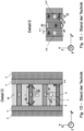
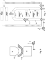
- the Figures 1A, 1B , 1C , 1D, 1E , 1F, 1G , 1H show a coke oven 1 in the manner of a horizontal chamber oven, with several oven chambers 2, each with a coal charge.
- the Furnace chambers 2 have a height z2 of, for example, 6 to 8m.
- the furnace chambers 2 are sealed off by runner walls 3, each of which extends in a yz plane.
- pairs of heating channels 5.1, 5.2 each form a twin heating flue 5, the inner wall 5.3 of which separates the heating space through which gases flow (free of coal) from the respective furnace chamber.
- the heating channels 5.1, 5.2 are operated alternately as a flamed or exhaust gas-carrying heating channel, which requires switching the flow direction and in a cycle of, for example, 20 minutes. he follows.
- the paired heating channels are each separated from one another by a coupling partition (binder wall) 4, in which a coupling passage 4.4 is provided at the top and bottom, via which a circulating flow 9 of recirculated exhaust gas can be realized.
- Adjacent twin heating flues are completely sealed off from each other by a partition wall 4a without any passages.
- a staged air duct 4.1 is arranged in the partition walls 4, 4a, which is coupled to the heating duct via at least one combustion stage 4.2 or the corresponding inlet or outlet.
- the respective combustion stage 4.2 is arranged in a characterizing height position z4. For example, two or three height positions z4 are defined, into which stepped air is admitted.
- the respective walls are made of stones, each of which defines a wall layer 3.1.
- the x-direction indicates the width of the furnace 1
- the y-direction indicates the depth (or the horizontal expression direction in a horizontal chamber furnace)
- the z-direction indicates the vertical (vertical axis).
- the central longitudinal axis M of the respective heating channel runs through the center of the respective heating channel, which is arranged centrally in the x and y directions with respect to the inner surfaces/inner walls.
- the center of each twin heating flue is not marked. It lies approximately in the center of the respective partition wall with a circular flow, in particular in the center of a centrally arranged stepped air duct.
- the term “centric” or “center” here refers to a center in the xy plane, and the term “center” or “center” here refers to the height direction (z).
- inlets are arranged, namely a (first) combustion air inlet 6, in particular for coke oven gas heating, and a further combustion air inlet 7, in particular for mixed gas heating, and a coke oven gas inlet 8 Gas introduced via the inlets flows upwards on the wall surfaces 4.3 of the partition walls and on the inner walls of the runner walls.
- the following temperatures at the coke oven 1 can be mentioned: nozzle stone temperature T1, (gas temperature T2 in the respective heating channel, and temperature T3 in the oven chamber.
- the present invention particularly relates to a distribution of the temperature T2 that is as homogeneous as possible.
- the gas stream G1 indicates newly admitted or supplied heating gas or combustion air.
- the gas stream G1 can comprise a gas stream G1a (coke oven gas) and/or a gas stream G1b (mixed gas).
- the gas stream G4 characterizes recirculation exhaust gases, which are returned or circulated.
- the gas flow G5 indicates gas or air from a respective combustion stage 4.2, 14.11, and the gas flow G6 indicates exhaust gases that are discharged from the respective heating duct or heating flue.
- the distance d4 between previously known passages 4.4 in the x direction is comparatively large.
- the distance d5 of the coke oven gas inlet 8 to the further inlets 6, 7 in the x direction in particular a distance between the coke oven gas inlet 8; G1a and the other admitted gas streams G1 are comparatively small.
- the distance d5 is smaller than the distance d4.
- the distance x4 of the respective passage 4.4 to the inner wall of the runner wall 3 is comparatively small (in particular, a distance of 120 to 140 mm was previously maintained between the runner wall and the outer edge of the passage).
- the distance x6, x8 of the inlet 6, 8 to the rotor wall 3 is comparatively large.
- the distance x8 is smaller than the distance x6.
- the distance x4 is significantly smaller than the distance x6, x8.
- Fig. 1G shows schematically a heating differential 5.6 with individual openings 5.61, through which the gas can be redirected in a head area of the heating channel.
- the heating differential 5.6 is separated from the respective twin heating flue by an (intermediate) ceiling 5.7.
- the heating differential 5.6 is independent of the circuit current 9.
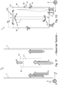
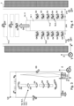
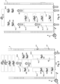
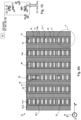
- FIG. 2 , 3 , 4 , 5 , 6 , 7 show the individual measures according to the invention for optimizing the temperature profile in the respective heating channel.
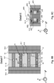
- FIG. 8A , 8B , 8C , 8D, 8E Individual measures are further illustrated in detail.
- a coke oven device 10 with oven chambers 10.2, in particular with horizontal chamber oven chambers, has a plurality of twin heating flues 13, each with a flamed heating channel 11 and a heating channel 12 carrying exhaust gas.
- the heating channels define with their inner wall 11.1 a heating cable for passing gases through.
- the individual heating channels are separated from one another by partition walls (binder wall) 14 with coupling passages 14.2 and isolating partition walls 14a without passages.
- At least one staged air channel 14.1 with one or more combustion stages 14.11 or inlets or outlets from/to the heating channel is provided in the partition walls 14, 14a.
- Runner walls 15 limit the furnace chambers and heating channels in the y direction.
- Gas can flow into the respective heating channel via several inlets 16, 17, 18, in particular via a first combustion air inlet 16, in particular for coke oven gas heating, via a further combustion air inlet 17, in particular for mixed gas heating, and via a coke oven gas inlet 18 or a coke oven gas nozzle.
- the admitted and recirculated gas flows downwards or upwards through the respective heating channel both centrally and on the inner surfaces 14.3, 15.1 of the respective partition or rotor wall.
- FIG. 2 one of the measures according to the invention is primarily illustrated.
- a circular current 19 is formed by several circular currents that flow around each other on several paths.
- an outer circular current path 19.1 is shown, which delimits and flows around two further inner circular current paths 19.2, 19.3, the inner circular current paths 19.2, 19.3 being defined via the corresponding additional exhaust gas recirculation passages 14.2.
- Fig. 2 shows an arrangement with three circular current paths 19.1, 19.2, 19.3, which run around a stepped air outlet 14.11 arranged at least approximately at half the height position in the heating duct.
- Staged gas G5 flows from the staged air outlet 14.11.
- staged air outlets can also be provided, in particular above the innermost circular current path 19.3.
- the optimization of the flow and heat profile can be carried out primarily by means of the recirculated gas G4, both in the floor area and in several height positions above.
- Fig. 3 shows an arrangement with more than three circuit current paths, the number of lower passages being greater than the number of upper passages.
- the optimization can be carried out, particularly in the floor area, primarily by means of recirculated gas G4, without the need for a stepped inlet of stepped gas.
- a heating differential 5.6 is provided in the head area of the heating channel, which can be switched on, for example using slide blocks, independently of the respective circulating currents.
- Fig. 4 shows an arrangement with more than three circuit current paths, with the number of lower passages being significantly larger than the number of upper passages.
- six lower passages (or pairs of passages) are provided in six different height positions.
- the lower passages are all arranged under a stepped air outlet 14.11 of a central stepped air duct.
- the six lower passages are provided in pairs adjacent to the stepped air duct, and the upper passages are individually provided and centrally arranged.
- a single central lower passage is arranged above the stepped air outlet. This arrangement results in a particularly wide central two-stream flow path from bottom to top, which is supplemented further above by staged gas and the centrally introduced recirculation gas.
- the cross-sectional area Q14 of the respective coupling passage 14.2 on the inner surface to the heating channel is described.
- the cross-sectional area Q14 is arranged above a stepped air duct 14.1
- Passages 14.2 is wider or more elongated than the cross-sectional area Q14 of passages 14.2 arranged laterally next to the stepped air duct 14.1.
- Fig. 5 shows an arrangement with compared to Fig. 4 several central step air outlets 14.11 and with passages with different cross sections: the lower passages are at least partially elongated in the z direction, and the upper passages are elongated in the x direction.
- the stepped air duct is surrounded on both sides by several lower passages, but not in pairs.
- the number of lower passages on one side is unequal to the number of passages on the other side.
- the passages stretched in the z-direction enable an advantageous relative arrangement, in particular very centrally (comparatively small distance d2), and in particular with an optimized flow profile.
- the comparatively large cross section Q14 of the passage shown on the right allows a strong flow effect of the admitted gas G1, especially over a large height section.
- a distance d2 between an inner wall/edge of the corresponding passage 14.2 and an outer wall/edge of a stepped air duct 14.1 arranged centrally in the heating flue is shown in the x direction to one another.
- this distance d2 is very small, in particular 30 to 100mm, preferably 50 to 70mm.
- the passages 14.2 can, according to the invention, be positioned as close as possible next to it in the x direction.
- Fig. 6 shows an arrangement with two staged air ducts, which open separately into the heating duct at several height positions. All lower passages 14.2 below the top step air outlet are arranged centrally, in particular symmetrically with respect to the central longitudinal axis. Above the staged air inlets 14.11, two further pairs of lower passages (four passages) are arranged in a width position (x) at least approximately corresponding to the width position of the staged gas outlets 14.11. The paired passages can also be arranged at several height positions, including directly next to each other on the side.
- the lower passages can also be designed to be narrower than the upper passage(s) and/or narrower than the uppermost lower passages.
- the uppermost lower passages can also be provided as single passages (not pairs) and be arranged in such a width position that step gas can flow past/along the respective passage and can mix with the recirculated gas.
- Fig. 7 shows an arrangement with two staged air ducts, which, combined together, open centrally into the heating channel in a height position between individual lower passages 14.2, with additional separate staged air outlets optionally being provided in the respective staged air duct.
- the central stepped air inlet 14.11 extends in particular over a width which completely overlaps the lower passage above.
- the lower passages are arranged offset from one another in the x direction by the offset x2.
- the offset x2 also provides the advantage of a particularly wide, homogeneous flow (without a stronger flowing core), especially with passages 14.2 that are comparatively wide in the x direction. The circulating current can thereby be made even more homogeneous.
- several upper passages can be provided. Such an offset can also occur in the in Fig. 6 shown arrangement can be provided.
- Fig. 7 an offset x2 in the x direction is illustrated.
- This offset between adjacent passages 14.2 is in particular 50 to 100 mm and provides the advantage of good heat distribution.
- the Fig. 2 , 3 , 4 , 5 , 6 , 7 all show recirculation with full circulating current in the circuit.
- the lower passage(s) can be dispensed with, especially if the measures described here are to or must be implemented independently of a full circuit flow, be it in individual twin heating flues or in the entire furnace device.
- Fig. 8A is shown schematically (in some heating channels) the arrangement of the inlets 16, 17, 18 opposite one another and spaced in the x direction from the central longitudinal axis as close as possible to the rotor walls 15. This arrangement can be selected for each of the heating channels or modified.
- Fig. 8B it is shown that the inlets 16, 17, 18 are arranged further outwards in the x direction than the passages 14.2.
- the passages are arranged at a distance d14 from one another that is smaller than the distance d15 of the inlets.
- Fig. 8C it is shown that the step gas G5 flowing in most centrally in the center is flowed around on both sides by recirculated gas G4, which is flowed around by admitted gas G1, G1a, G1b further out.
- the in Fig. 8C Angle ⁇ shown, in particular relating to the coke oven gas inlet 18, is set excessively large for better understanding. According to the invention, the angle ⁇ can be particularly small, in particular converge to zero or be 0°. Depending on the design of the central structure, an angle in the range of 5 to 10° can also be a rational compromise between additional constructive, technical effort and the achieved flow effect.
- the passages 14.2 shown or the stepped gas inlet 14.11 can be arranged in the arrangement, number and geometry according to the in Fig. 2 to 7 The variants discussed can be varied.
- the individual gas streams G1, G1a, G4, G5 shown show how, according to the invention, a separation of the gas streams or a parallel flow can be achieved at least over a certain height section.
- the distance d14 between the passages 14.2 in the x direction is comparatively small, in particular less than 50, 45, 40, 35 or 30 percent of the width (x) of the heating channel.
- the distance d15 of the coke oven gas inlet 18 to the further inlets 16, 17 in the x direction is comparatively large, in particular greater than 70, 75, 80 or 85 percent of the width (x) of the heating channel.
- the distance d15 is significantly larger than the distance d14, in particular at least 35, 40, 45, 50 or 55 percent larger.
- the distance x14 of the respective passage 14.2 to the inner wall of the rotor wall 3 is comparatively large, in particular greater than 35, 40 or 45 percent of the width (x) of the heating channel (for paired passages).
- the distance x14 is at least greater than 40 percent of the width (x) of the heating channel, especially in the floor area.
- the distance x16, x18 of the inlet 6, 8 to the rotor wall 15 is comparatively small, in particular less than 20, 15 or 10 percent of the width (x) of the heating channel.
- the distance x16, x18 is each smaller than the distance x14.
- the distance x14 is at least twice or at least three times as large as the distance x16, x18.
- the respective gas flow path GP1 characterizes inflow paths according to the invention or flow paths for at least one of the gases G1 introduced via the inlets.
- the respective gas flow path GP4 indicates flow paths according to the invention of recirculated exhaust gas/flue gas G4, and the respective gas flow path GP5 indicates flow paths according to the invention of gas G5 introduced in stages.
- the in Fig. 8C , 8E illustrated inflow angle ⁇ is preferably smaller than 30°, in particular smaller than 10° in each case with respect to the z-axis.
- the inflow angle ⁇ can also be implemented analogously for the other inlets 17, 18.
- the respective y position of the individual inlets can in particular be central.
- the distances and relative positions mentioned in relation to the respective inlets and passages can also relate reciprocally to the distances and relative positions of the respective gas flow paths/circular flow paths, at least in a section upstream of a subsequent mixing with neighboring gas flows.
- a passage cross-section is shown in the yz plane.
- the recirculated gas G4 flows through the respective lower passage 14.2 coming from above and also flows upwards again.
- the gas G4 flows around two rounded flow edges 14.21 and flows past two sharp flow edges 14.22.
- the partition 14 limits the passage at the top with a convex curvature downwards. This promotes low flow resistance.
- the partition 14 also limits the passage at the bottom.
- the circular flow which here has a very narrow radius, can therefore flow through the passage and be redirected upwards without strong turbulence.
- One or more sharp edges 14.22 can limit a flow downwards.
- This type of flow optimization also makes it possible to achieve a major effect through the way the new gases are admitted.
- the recirculated gases G4 generate little or no turbulence, so that the flow profile can be effectively optimized using the inlets.
- the coke oven device 10 can have a control unit 20, set up to control/regulate one of the previously described volume flows V (t), in particular at least the volume flows G1, G1a, G1b, G4, G5, G6. Controlling and adjusting the volume flows makes it possible to influence the flow and temperature profile in the respective heating channel 11, 12. The NOx emissions can therefore also be adjusted indirectly via the volume flows.
- Fig. 11, 12 show variants of the in Fig. 5 shown embodiment.
- Fig. 11 some of the lower passages arranged above the top step air outlet are formed in pairs, with a single larger, wider lower passage being provided.
- the ones in the Fig. 2 to 12 The positions of the passages shown are shown as examples. Each inlet can be arranged and oriented independently of the other inlets. The exemplary embodiments shown can in particular also be varied by varying the arrangement of the lower passages, or by omitting individual or all lower passages.
- the arrangement and size of the passages in particular the passages arranged above the top step air outlet and/or the passages arranged in a height position between individual step air outlets, can be varied by changing to pairs of passages. Some or all of the passages arranged in the floor area can also be dispensed with, especially if these passages are moved further upwards to a height range above 500mm.
- the number of stepped air outlets or height positions with steps is not limited to the variants shown.
Landscapes
- Chemical & Material Sciences (AREA)
- Engineering & Computer Science (AREA)
- Combustion & Propulsion (AREA)
- Materials Engineering (AREA)
- Oil, Petroleum & Natural Gas (AREA)
- Organic Chemistry (AREA)
- Coke Industry (AREA)
Claims (15)
- Dispositif de four à coke (10) pour la production de coke par cokéfaction de charbon ou de mélanges de charbon, le dispositif de four à coke étant conçu pour minimiser l'émission d'oxyde d'azote par compensation interne de l'énergie thermique au moyen de gaz propres au four à coke (G1, G4, G5) par des mesures internes au dispositif de four à coke, avec une pluralité de carneaux de chauffage jumelés (13), chacun avec un canal de chauffage (11) parcouru par des flammes de gaz et un canal de chauffage (12) parcouru vers le bas par les gaz d'échappement, lesquels canaux de chauffage sont délimités les uns des autres par paires par une paroi de séparation (14) et sont séparés d'une chambre de four respective (10, 11, 12) par deux parois de rotor (15) opposées l'une à l'autre.2), les canaux de chauffage par paires étant isolés du point de vue de la technique d'écoulement au moyen d'un passage supérieur de couplage (14.2) et, au choix, également au moyen d'un passage inférieur de couplage, sont couplés l'un à l'autre respectivement pour la recirculation interne des gaz d'échappement (19) sur une voie de courant circulaire extérieure (19.1), au moins une entrée du groupe suivant étant prévue dans la zone inférieure au fond (5.4) du double parcours de chauffage respectif : entrée de gaz de four à coke (18), entrée d'air de combustion (16), entrée de gaz mixte (17) ; au moins un passage de recirculation des gaz d'échappement (14.2) est disposée de manière plus centrée par rapport à la largeur (x) du conduit de chauffage qu'au moins l'une des entrées (16, 17, 18) comprenant l'entrée de gaz mixte (17), et définit un trajet d'écoulement plus centré (GP4) entouré par au moins l'un des gaz admis (G1, G5),
en ce qu'au moins deux des entrées (16, 17, 18) sont disposées de part et d'autre des passages de couplage (14.2) plus près des parois du rotor (15) de telle sorte que le passage de recirculation des gaz d'échappement (14.2) respectif entre les entrées (16, 17, 18) entoure latéralement ou est entouré par les parois du rotor (15). est disposé de manière délimitée par rapport aux entrées (16, 17, 18) et qu'au moins trois ou quatre courants partiels s'écoulant vers le haut se forment dans le canal de chauffage correspondant sur des chemins d'écoulement qui s'étendent au moins approximativement parallèlement les uns aux autres ou au moins les uns à côté des autres au moins sur une section de hauteur dans la plage de hauteur de 0 à 1000 mm et conduisent à un mélange retardé dans cette section de hauteur, de sorte qu'un mélange complet ne se produit qu'au-dessus de cette section de hauteur. - Dispositif de four à coke selon la revendication précédente, dans lequel tous les passages de recirculation des gaz d'échappement (14.2) sont disposés de manière plus centrée par rapport à la largeur (x) du canal de chauffage que toutes les entrées (16, 17, 18).
- Dispositif de four à coke selon l'une des revendications précédentes, dans lequel l'entrée d'air de combustion (16) respective et/ou l'entrée de gaz mixte (17) respective et/ou l'entrée de gaz de four à coke (18) respective présentent une surface de section transversale de 0,06m2 maximum ; et/ou dans lequel la surface de section transversale du passage de recirculation des gaz d'échappement (14.2) est supérieure à 0,005m2, en particulier supérieure à 0,01m2 ; et/ou dans lequel l'entrée d'air de combustion (16) et/ou l'entrée de gaz mélangés (17) et/ou l'entrée de gaz de four à coke (18) sont orientées selon un angle (α) de 0° par rapport à l'axe longitudinal médian du canal de chauffage ou selon un angle inférieur à 30°, en particulier inférieur à 20° ou inférieur à 10°.
- Dispositif de four à coke selon l'une des revendications précédentes, dans lequel la paroi de séparation respective (14) présente au moins un autre passage de couplage inférieur et/ou supérieur (14.2) qui, dans une position en hauteur plus centrale, est disposé plus près du milieu en hauteur des canaux de chauffage que le trajet de courant circulaire extérieur (19.1) et est aménagé pour former une couche intermédiaire inerte intérieure sur le trajet d'écoulement central (GP4) ; et/ou dans lequel la paroi de séparation respective (14) présente au moins un autre passage de couplage inférieur et/ou supérieur (14.2), qui est disposé dans une position en hauteur plus centrale, plus près du centre en hauteur des canaux de chauffage que le trajet de courant circulaire extérieur (19.1) et qui est aménagé pour un courant circulaire intérieur supplémentaire pour former une couche intermédiaire inerte intérieure sur un trajet de courant circulaire intérieur (19.2, 19.3).
- Dispositif de four à coke selon l'une des revendications précédentes, dans lequel au moins un canal d'air étagé (14.1) disposé en particulier au centre avec au moins une entrée d'air étagé (14.11) est formé dans la paroi de séparation (14) ; ou dans lequel au moins deux canaux d'air étagé (14.1) disposés en particulier parallèlement sont formés dans la paroi de séparation (14), lesquels se réunissent au-dessus du passage de recirculation des gaz d'échappement supérieur/supérieur (14.2) et débouchent dans une entrée d'air étagé supérieure (14.11) au-dessus de tous les passages de recirculation des gaz d'échappement (14.2) dans le canal de chauffage exposé aux flammes (11) ; et/ou dans lequel au moins deux canaux d'air étagés (14.1) disposés en particulier parallèlement sont formés dans au moins l'une des parois de séparation (14), lesquels débouchent au-dessus du passage de recirculation des gaz d'échappement supérieur/supérieur (14.2) dans deux entrées d'air étagées supérieures (14.11) au-dessus de tous les passages de recirculation des gaz d'échappement dans le canal de chauffage exposé aux flammes (11).
- Dispositif de four à coke selon l'une des revendications précédentes, dans lequel le passage de recirculation des gaz d'échappement respectif (14.2) présente au moins une arête d'écoulement arrondie (14.21) et/ou une courbure convexe, en particulier avec un rayon d'au moins un quart de couche de paroi ou d'au moins 30°, en particulier une arête d'écoulement arrondie ou une courbure convexe située à l'intérieur par rapport au trajet de courant circulaire respectif ; et/ou dans lequel le passage de recirculation des gaz d'échappement respectif présente au moins une arête d'écoulement vive (14.22) et/ou une courbure concave, en particulier avec un rayon d'au maximum une ou deux couches de paroi ou 120 mm, en particulier une arête d'écoulement vive ou une courbure concave située à l'extérieur par rapport au trajet de courant circulaire respectif ; et/ou dans lequel le passage de recirculation des gaz d'échappement respectif (14.2) présente au moins un contour d'écoulement avec au moins un rayon et au moins une arête d'écoulement vive.
- Dispositif de four à coke selon l'une des revendications précédentes, dans lequel au moins l'une des entrées, en particulier l'entrée de gaz de four à coke (18), comprend une buse d'entrée et débouche dans le canal de chauffage (11, 12) à une position en hauteur de 0,0 à 0,45m, en particulier de 0,05 à 0,25m au-dessus du fond du canal de chauffage.
- Procédé d'exploitation d'un dispositif de four à coke (10) pour la production de coke par cokéfaction de charbon ou de mélanges de charbon avec une émission minimisée optimisée d'oxydes d'azote par compensation interne d'énergie thermique au moyen de gaz propres au four à coke (G1, G4, G5) par des mesures internes au dispositif de four à coke, en particulier pour l'exploitation d'un dispositif de four à coke selon l'une des revendications précédentes, dans lequel, dans un double parcours de chauffage (13) respectif du dispositif de four à coke avec un canal de chauffage (11) exposé aux flammes et un canal de chauffage (12) conduisant les gaz d'échappement, au moyen d'au moins un passage de couplage (14.2) à travers une paroi de séparation (14), on règle une recirculation interne des gaz d'échappement (19) sur un trajet de courant circulaire extérieur (19.1) autour de la paroi de séparation, au moins un gaz du groupe suivant étant admis dans la zone inférieure au fond (5.4) du carneau de chauffage jumelé respectif : Gaz de four à coke (G1a), air de combustion (G1), gaz mixte (G1b), la recirculation des gaz d'échappement (19) étant guidée sur un/un chemin de courant circulaire (19.1, 19.2, 19.3) ou au moins un chemin d'écoulement centré (GP4) respectivement plus centré que les gaz introduits (G1a, G1, G1b) comprenant le gaz mixte (G1b), en particulier délimité des deux côtés par les gaz introduits,
en ce qu'au moins deux des entrées (16, 17, 18) sont disposées de part et d'autre des passages de couplage (14.2) plus près des parois du rotor (15), de telle sorte que le passage de recirculation des gaz d'échappement (14.2) respectif entre les entrées (16, 17, 18) est entouré latéralement ou est situé à une distance de plus en plus grande des parois du rotor (15). au moins trois ou quatre courants partiels s'écoulant vers le haut se forment dans le canal de chauffage correspondant sur des chemins d'écoulement qui s'étendent au moins approximativement parallèlement les uns aux autres ou au moins les uns à côté des autres au moins sur une section de hauteur dans la plage de hauteur de 0 à 1000 mm et conduisent à un mélange retardé dans cette section de hauteur, de telle sorte qu'un mélange complet ne se produit qu'au-dessus de cette section de hauteur. - Procédé selon la revendication de procédé précédente, dans lequel au moins un courant circulaire interne supplémentaire (19.2, 19.3) est réglé plus centré que les gaz admis (G1) et plus à l'intérieur que le trajet de courant circulaire externe (19.1) et délimité par le trajet de courant circulaire externe, en particulier via au moins une paire de passages supplémentaires (14.2) en haut et en bas.
- Procédé selon l'une des revendications précédentes, dans lequel la proportion de gaz de combustion circulant sur le ou les trajets de courant de circulation (19.1, 19.2, 19.3) est réglée
à plus de 50%, en particulier à plus de 70%, en particulier à 80%, dans le cas d'un chauffage au gaz riche ou d'un chauffage au gaz mixte ; et/ou dans lequel le procédé est mis en oeuvre pour un chauffage au gaz riche en utilisant essentiellement du gaz de four à coke ou en utilisant un gaz riche appauvri avec un pouvoir calorifique inférieur réduit, en particulier inférieur à 17000kJ/Nm3 ; ou le procédé est réalisé pour un chauffage au gaz mixte, en utilisant essentiellement un mélange de gaz de haut fourneau, de gaz de cokerie et, en option, de gaz de convertisseur ; ou le procédé est réalisé avec du gaz naturel en remplacement au moins partiel du gaz de cokerie. - Procédé selon l'une des revendications de procédé précédentes, dans lequel un rapport de combustion sous-stoechiométrique de <0,9 est réglé, en particulier un rapport de combustion dans la plage de 0,5 à 0,8, en particulier 0,7, en particulier dans le plan du brûleur (5.4) au fond du canal de chauffage respectif (11, 12).
- Procédé selon l'une des revendications précédentes, dans lequel une couche intermédiaire est formée au moyen du gaz d'échappement recirculé (G4) entre le gaz admis (G1) et un canal d'air étagé (14.1) ou du gaz (G5) provenant du canal d'air étagé, en particulier dans une plage de hauteur de 5 à 75 % ou de 15 à 50 % de la hauteur du canal de chauffage ou sur une section de hauteur de 0,25 à 4 m ; et/ou dans lequel un tapis de gaz est formé entre la paroi de rotor respective (15) et le ou les trajets de courant circulaire (19.1, 19.2, 19.3) au moyen du gaz introduit (G1).
- Procédé selon l'une des revendications de procédé précédentes, dans lequel la proportion des quantités de gaz introduites entre un premier étage, en particulier au sol (5.4) par l'entrée d'air de combustion et de gaz mixte (16, 17), et un deuxième étage (z4) est réglée à 50:50 ou avec une proportion encore plus faible du premier étage, en particulier avec un chauffage à gaz fort ; et/ou dans lequel le rapport des débits volumiques introduits dans les canaux de chauffage (11, 12) est réglé comme suit : <30% par l'entrée d'air de combustion (16), <30% par l'entrée de gaz mélangés (17), et >40% par les passages de recirculation et éventuellement au moins une entrée d'air étagée (14.11), en particulier avec un chauffage au gaz fort ; et/ou dans lequel le débit volumique introduit dans la chambre de four à l'entrée d'air de combustion et à l'entrée de gaz mixte est réglé entre 45 et 55 % du débit volumique introduit par les passages de recirculation et, en option, par la au moins une entrée d'air étagée, en particulier avec un chauffage au gaz fort.
- Dispositif de commande (20) aménagé pour exécuter un procédé selon l'une des revendications de procédé précédentes, dans lequel les débits volumiques (G1, G4, G5) introduits dans les canaux de chauffage (11, 12) sont réglés selon les rapports selon la revendication 13.
- Utilisation de gaz riche appauvri ayant un pouvoir calorifique inférieur abaissé pour faire fonctionner un dispositif de four à coke selon un procédé selon l'une des revendications de procédé précédentes, en particulier dans un dispositif de four à coke selon l'une des revendications de dispositif précédentes.
Applications Claiming Priority (4)
| Application Number | Priority Date | Filing Date | Title |
|---|---|---|---|
| DE102017216437.9A DE102017216437A1 (de) | 2017-09-15 | 2017-09-15 | Koksofenvorrichtung mit exzentrischen Einlässen zum Herstellen von Koks und Verfahren zum Betreiben der Koksofenvorrichtung sowie Steuerungseinrichtung und Verwendung |
| DE102017216436.0A DE102017216436A1 (de) | 2017-09-15 | 2017-09-15 | Koksofenvorrichtung mit zentrischer Rezirkulation zum Herstellen von Koks und Verfahren zum Betreiben der Koksofenvorrichtung sowie Steuerungseinrichtung und Verwendung |
| DE102017216439.5A DE102017216439A1 (de) | 2017-09-15 | 2017-09-15 | Koksofenvorrichtung mit umströmtem Kreisstrompfad zum Herstellen von Koks und Verfahren zum Betreiben der Koksofenvorrichtung sowie Steuerungseinrichtung und Verwendung |
| PCT/EP2018/074700 WO2019053105A1 (fr) | 2017-09-15 | 2018-09-13 | Dispositif de four à coke présentant une recirculation centrale pour la fabrication de coke et procédé de fonctionnement du dispositif de four à coke ainsi qu'installation de commande et utilisation |
Publications (2)
| Publication Number | Publication Date |
|---|---|
| EP3681978A1 EP3681978A1 (fr) | 2020-07-22 |
| EP3681978B1 true EP3681978B1 (fr) | 2023-12-27 |
Family
ID=63586706
Family Applications (3)
| Application Number | Title | Priority Date | Filing Date |
|---|---|---|---|
| EP18769665.3A Active EP3681979B1 (fr) | 2017-09-15 | 2018-09-13 | Dispositif de four à coke muni d'admissions excentriques pour la fabrication de coke et procédé pour faire fonctionner le dispositif de four à coke ainsi que dispositif de commande et utilisation |
| EP18769663.8A Active EP3681977B1 (fr) | 2017-09-15 | 2018-09-13 | Dispositif de four à coke à chemin d'écoulement circulaire contourné par un flux, destiné à fabriquer du coke et procédé de fonctionnement du dispositif de four à coke et équipement de commande et utilisation |
| EP18769664.6A Active EP3681978B1 (fr) | 2017-09-15 | 2018-09-13 | Dispositif de four à coke présentant une recirculation centrale pour la fabrication de coke et procédé de fonctionnement du dispositif de four à coke ainsi qu'installation de commande et utilisation |
Family Applications Before (2)
| Application Number | Title | Priority Date | Filing Date |
|---|---|---|---|
| EP18769665.3A Active EP3681979B1 (fr) | 2017-09-15 | 2018-09-13 | Dispositif de four à coke muni d'admissions excentriques pour la fabrication de coke et procédé pour faire fonctionner le dispositif de four à coke ainsi que dispositif de commande et utilisation |
| EP18769663.8A Active EP3681977B1 (fr) | 2017-09-15 | 2018-09-13 | Dispositif de four à coke à chemin d'écoulement circulaire contourné par un flux, destiné à fabriquer du coke et procédé de fonctionnement du dispositif de four à coke et équipement de commande et utilisation |
Country Status (5)
| Country | Link |
|---|---|
| EP (3) | EP3681979B1 (fr) |
| CN (3) | CN111492038B (fr) |
| PL (3) | PL3681977T3 (fr) |
| TW (3) | TWI681048B (fr) |
| WO (3) | WO2019053103A1 (fr) |
Families Citing this family (3)
| Publication number | Priority date | Publication date | Assignee | Title |
|---|---|---|---|---|
| DE102019206628B4 (de) * | 2019-05-08 | 2024-04-18 | Thyssenkrupp Ag | Koksofenvorrichtung zum Herstellen von Koks und Verfahren zum Betreiben der Koksofenvorrichtung sowie Verwendung |
| CN112724994A (zh) * | 2020-12-29 | 2021-04-30 | 黑龙江建龙化工有限公司 | 一种新型判断配用煤影响冶金焦质量方法 |
| CN113025349B (zh) * | 2021-03-09 | 2024-07-09 | 中冶焦耐(大连)工程技术有限公司 | 一种分段加热分段废气循环的焦炉立火道结构 |
Citations (26)
| Publication number | Priority date | Publication date | Assignee | Title |
|---|---|---|---|---|
| DE613606C (de) | 1930-06-06 | 1935-05-22 | Didier Werke Akt Ges | Ofen zum Erzeugen von Gas und Koks mit Zugumkehr in den paarweise zusammenwirkenden senkrechten Heizzuegen |
| DE618969C (de) | 1932-03-02 | 1935-09-19 | Mueller Wilhelm | Regenerativ-Verbund-Koksofen |
| AT147818B (de) | 1934-12-21 | 1936-11-25 | Didier Werke Ag | Koks- und Gaserzeugungsofen. |
| DE735312C (de) | 1938-09-09 | 1943-05-12 | Koppers Gmbh Heinrich | Verbundkoksofen mit Zwillingsheizzuegen und Kreisstrombeheizung |
| US3170851A (en) | 1961-08-16 | 1965-02-23 | Koppers Co Inc | Downflow horizontal coking retort oven |
| US3996109A (en) | 1974-06-05 | 1976-12-07 | Dr. C. Otto & Comp. G.M.B.H. | Coke oven battery having twin heating flues |
| EP0068304B1 (fr) | 1981-07-01 | 1987-09-23 | Krupp Koppers GmbH | Procédé pour le chauffage de fours à coke et installation pour la mise en oeuvre du procédé |
| DE3911295A1 (de) | 1988-04-24 | 1989-11-09 | Still Otto Gmbh | Verfahren und vorrichtung zur minderung des stickoxidgehaltes von rauchgasen aus verkokungsofenbatterien |
| DE4006217A1 (de) | 1989-05-26 | 1990-11-29 | Didier Ofu Eng | Beheizungssystem fuer regenerativverkokungsoefen |
| US5017270A (en) | 1988-04-15 | 1991-05-21 | Krupp Koppers Gmbh | Method of reducing nox-content in flue gas during heating of coking oven |
| US5062925A (en) | 1988-12-10 | 1991-11-05 | Krupp Koppers Gmbh | Method of reducing the nitrogen dioxide content of flue gas from a coke oven with dual heating flues by a combination of external flue gas feed back and internal flue gas recirculation |
| JPH07118641A (ja) | 1993-10-27 | 1995-05-09 | Sumitomo Metal Ind Ltd | コークス炉の炉高方向均一加熱方法および装置 |
| JPH10265778A (ja) | 1997-03-26 | 1998-10-06 | Nkk Corp | コークス炉の燃焼室 |
| JPH11323344A (ja) | 1998-05-08 | 1999-11-26 | Sumitomo Metal Ind Ltd | コークス炉燃焼排ガス中のNOx低減方法 |
| JP2000008043A (ja) | 1998-06-19 | 2000-01-11 | Nippon Steel Corp | コークス炉の燃焼室構造及び燃焼方法、燃焼装置 |
| JP2001003055A (ja) | 1999-06-17 | 2001-01-09 | Sumitomo Metal Ind Ltd | 複式コークス炉燃焼排ガス中の窒素酸化物低減方法 |
| US6797122B1 (en) | 1999-03-04 | 2004-09-28 | The Japan Iron And Steel Federation | Coke oven and method of operating the same |
| CN102268266A (zh) | 2011-06-21 | 2011-12-07 | 中冶焦耐(大连)工程技术有限公司 | 一种可控多段燃烧加热型焦炉 |
| CN202116492U (zh) | 2011-06-21 | 2012-01-18 | 中冶焦耐(大连)工程技术有限公司 | 一种可控多段燃烧加热型焦炉 |
| JP2012052021A (ja) | 2010-09-01 | 2012-03-15 | Sumitomo Metal Ind Ltd | コークス炉 |
| US20120261244A1 (en) | 2009-11-18 | 2012-10-18 | Joerg Brix | Method of reducing nitrogen oxides from coke-oven flue gas |
| CN202953979U (zh) | 2012-11-13 | 2013-05-29 | 中冶焦耐工程技术有限公司 | 一种焦炉 |
| CN104449768A (zh) | 2014-11-21 | 2015-03-25 | 中冶焦耐工程技术有限公司 | 一种下调式焦炉燃烧室立火道燃烧调节方法及其加热系统 |
| CN204265686U (zh) | 2014-11-21 | 2015-04-15 | 中冶焦耐工程技术有限公司 | 一种下调式焦炉的加热系统 |
| CN105349158A (zh) | 2015-12-02 | 2016-02-24 | 中冶焦耐工程技术有限公司 | 一种降低焦炉氮氧化物生成的方法及立火道底部结构 |
| CN107033926A (zh) | 2017-06-20 | 2017-08-11 | 中冶焦耐(大连)工程技术有限公司 | 实现低氮氧化物燃烧的焦炉燃烧室立火道结构 |
Family Cites Families (17)
| Publication number | Priority date | Publication date | Assignee | Title |
|---|---|---|---|---|
| GB641221A (en) * | 1945-08-31 | 1950-08-09 | Cie Gen De Constr De Fours | Improvements in ovens, in particular, coke ovens |
| GB821496A (en) | 1957-08-16 | 1959-10-07 | Koppers Gmbh Heinrich | Improvements relating to gas-heated ovens |
| JPS5145103A (en) * | 1974-10-16 | 1976-04-17 | Osaka Gas Co Ltd | Kookusuronenshohaigasuno shorihoho |
| DE3443976A1 (de) * | 1984-12-01 | 1986-06-12 | Krupp Koppers GmbH, 4300 Essen | Verfahren zur verringerung des no(pfeil abwaerts)x(pfeil abwaerts)-gehaltes im rauchgas bei der beheizung von verkokungsoefen und verkokungsofen zur durchfuehrung des verfahrens |
| CN85103685B (zh) * | 1985-05-14 | 1987-07-29 | 武汉钢铁公司技术部 | 焦炉火道四联循环方法 |
| DE3916728C1 (fr) | 1989-05-23 | 1990-12-20 | Ruhrkohle Ag, 4300 Essen, De | |
| DE4317070A1 (de) * | 1993-05-21 | 1994-11-24 | Alwin Dipl Ing Merz | Verfahren zum Einbau von Betonplatten |
| AU2013206820B2 (en) * | 2006-04-11 | 2015-12-17 | Thermo Technologies, Llc | Methods and apparatus for solid carbonaceous materials synthesis gas generation |
| DE102009015270A1 (de) | 2009-04-01 | 2010-10-14 | Uhde Gmbh | Verkokungsanlage mit Abgasrückführung |
| CN102250629B (zh) * | 2011-06-13 | 2013-09-04 | 山西利华新科技开发有限公司 | 一种热能循环利用的焦化炉及炼焦方法 |
| CN102517042B (zh) * | 2011-06-21 | 2014-05-21 | 中冶焦耐(大连)工程技术有限公司 | 一种可控制多段燃烧的焦炉加热方法 |
| CN102925164A (zh) * | 2012-11-13 | 2013-02-13 | 中冶焦耐工程技术有限公司 | 一种焦炉加热方法 |
| DE102013101912A1 (de) * | 2013-02-26 | 2014-08-28 | Thyssenkrupp Industrial Solutions Gmbh | Vorrichtung zum Ausdrücken von Koks aus einer Ofenkammer eines Koksofens |
| PL3186340T3 (pl) * | 2014-08-28 | 2021-04-19 | Suncoke Technology And Development Llc | Sposób i system do optymalizacji i wydajności instalacji koksowniczej |
| CN105385462A (zh) * | 2015-12-02 | 2016-03-09 | 中冶焦耐工程技术有限公司 | 一种有效降低焦炉氮氧化物生成的方法 |
| CN106190184A (zh) * | 2016-08-12 | 2016-12-07 | 湖南千盟智能信息技术有限公司 | 一种降低NOx生成的焦炉加热方法及装置 |
| CN107057720B (zh) * | 2017-06-20 | 2019-10-18 | 中冶焦耐(大连)工程技术有限公司 | 一种焦炉燃烧室立火道结构 |
-
2018
- 2018-06-25 TW TW107121686A patent/TWI681048B/zh active
- 2018-08-02 TW TW107126843A patent/TWI681049B/zh active
- 2018-08-02 TW TW107126844A patent/TWI682027B/zh active
- 2018-09-13 EP EP18769665.3A patent/EP3681979B1/fr active Active
- 2018-09-13 PL PL18769663.8T patent/PL3681977T3/pl unknown
- 2018-09-13 WO PCT/EP2018/074698 patent/WO2019053103A1/fr not_active Ceased
- 2018-09-13 WO PCT/EP2018/074702 patent/WO2019053107A1/fr not_active Ceased
- 2018-09-13 WO PCT/EP2018/074700 patent/WO2019053105A1/fr not_active Ceased
- 2018-09-13 EP EP18769663.8A patent/EP3681977B1/fr active Active
- 2018-09-13 CN CN201880059882.5A patent/CN111492038B/zh active Active
- 2018-09-13 PL PL18769665.3T patent/PL3681979T3/pl unknown
- 2018-09-13 PL PL18769664.6T patent/PL3681978T3/pl unknown
- 2018-09-13 CN CN201880059962.0A patent/CN111479902B/zh active Active
- 2018-09-13 EP EP18769664.6A patent/EP3681978B1/fr active Active
- 2018-09-13 CN CN201880059927.9A patent/CN111436202B/zh active Active
Patent Citations (26)
| Publication number | Priority date | Publication date | Assignee | Title |
|---|---|---|---|---|
| DE613606C (de) | 1930-06-06 | 1935-05-22 | Didier Werke Akt Ges | Ofen zum Erzeugen von Gas und Koks mit Zugumkehr in den paarweise zusammenwirkenden senkrechten Heizzuegen |
| DE618969C (de) | 1932-03-02 | 1935-09-19 | Mueller Wilhelm | Regenerativ-Verbund-Koksofen |
| AT147818B (de) | 1934-12-21 | 1936-11-25 | Didier Werke Ag | Koks- und Gaserzeugungsofen. |
| DE735312C (de) | 1938-09-09 | 1943-05-12 | Koppers Gmbh Heinrich | Verbundkoksofen mit Zwillingsheizzuegen und Kreisstrombeheizung |
| US3170851A (en) | 1961-08-16 | 1965-02-23 | Koppers Co Inc | Downflow horizontal coking retort oven |
| US3996109A (en) | 1974-06-05 | 1976-12-07 | Dr. C. Otto & Comp. G.M.B.H. | Coke oven battery having twin heating flues |
| EP0068304B1 (fr) | 1981-07-01 | 1987-09-23 | Krupp Koppers GmbH | Procédé pour le chauffage de fours à coke et installation pour la mise en oeuvre du procédé |
| US5017270A (en) | 1988-04-15 | 1991-05-21 | Krupp Koppers Gmbh | Method of reducing nox-content in flue gas during heating of coking oven |
| DE3911295A1 (de) | 1988-04-24 | 1989-11-09 | Still Otto Gmbh | Verfahren und vorrichtung zur minderung des stickoxidgehaltes von rauchgasen aus verkokungsofenbatterien |
| US5062925A (en) | 1988-12-10 | 1991-11-05 | Krupp Koppers Gmbh | Method of reducing the nitrogen dioxide content of flue gas from a coke oven with dual heating flues by a combination of external flue gas feed back and internal flue gas recirculation |
| DE4006217A1 (de) | 1989-05-26 | 1990-11-29 | Didier Ofu Eng | Beheizungssystem fuer regenerativverkokungsoefen |
| JPH07118641A (ja) | 1993-10-27 | 1995-05-09 | Sumitomo Metal Ind Ltd | コークス炉の炉高方向均一加熱方法および装置 |
| JPH10265778A (ja) | 1997-03-26 | 1998-10-06 | Nkk Corp | コークス炉の燃焼室 |
| JPH11323344A (ja) | 1998-05-08 | 1999-11-26 | Sumitomo Metal Ind Ltd | コークス炉燃焼排ガス中のNOx低減方法 |
| JP2000008043A (ja) | 1998-06-19 | 2000-01-11 | Nippon Steel Corp | コークス炉の燃焼室構造及び燃焼方法、燃焼装置 |
| US6797122B1 (en) | 1999-03-04 | 2004-09-28 | The Japan Iron And Steel Federation | Coke oven and method of operating the same |
| JP2001003055A (ja) | 1999-06-17 | 2001-01-09 | Sumitomo Metal Ind Ltd | 複式コークス炉燃焼排ガス中の窒素酸化物低減方法 |
| US20120261244A1 (en) | 2009-11-18 | 2012-10-18 | Joerg Brix | Method of reducing nitrogen oxides from coke-oven flue gas |
| JP2012052021A (ja) | 2010-09-01 | 2012-03-15 | Sumitomo Metal Ind Ltd | コークス炉 |
| CN202116492U (zh) | 2011-06-21 | 2012-01-18 | 中冶焦耐(大连)工程技术有限公司 | 一种可控多段燃烧加热型焦炉 |
| CN102268266A (zh) | 2011-06-21 | 2011-12-07 | 中冶焦耐(大连)工程技术有限公司 | 一种可控多段燃烧加热型焦炉 |
| CN202953979U (zh) | 2012-11-13 | 2013-05-29 | 中冶焦耐工程技术有限公司 | 一种焦炉 |
| CN104449768A (zh) | 2014-11-21 | 2015-03-25 | 中冶焦耐工程技术有限公司 | 一种下调式焦炉燃烧室立火道燃烧调节方法及其加热系统 |
| CN204265686U (zh) | 2014-11-21 | 2015-04-15 | 中冶焦耐工程技术有限公司 | 一种下调式焦炉的加热系统 |
| CN105349158A (zh) | 2015-12-02 | 2016-02-24 | 中冶焦耐工程技术有限公司 | 一种降低焦炉氮氧化物生成的方法及立火道底部结构 |
| CN107033926A (zh) | 2017-06-20 | 2017-08-11 | 中冶焦耐(大连)工程技术有限公司 | 实现低氮氧化物燃烧的焦炉燃烧室立火道结构 |
Non-Patent Citations (14)
Also Published As
| Publication number | Publication date |
|---|---|
| EP3681977B1 (fr) | 2023-12-27 |
| CN111479902B (zh) | 2022-03-04 |
| PL3681979T3 (pl) | 2024-03-25 |
| TWI682027B (zh) | 2020-01-11 |
| PL3681978T3 (pl) | 2024-06-24 |
| WO2019053103A1 (fr) | 2019-03-21 |
| PL3681977T3 (pl) | 2024-06-24 |
| EP3681979B1 (fr) | 2023-11-01 |
| CN111436202B (zh) | 2021-10-15 |
| EP3681978A1 (fr) | 2020-07-22 |
| EP3681979A1 (fr) | 2020-07-22 |
| CN111436202A (zh) | 2020-07-21 |
| TW201915150A (zh) | 2019-04-16 |
| TW201915152A (zh) | 2019-04-16 |
| TWI681049B (zh) | 2020-01-01 |
| WO2019053105A1 (fr) | 2019-03-21 |
| CN111492038B (zh) | 2022-02-22 |
| WO2019053107A1 (fr) | 2019-03-21 |
| CN111492038A (zh) | 2020-08-04 |
| TWI681048B (zh) | 2020-01-01 |
| CN111479902A (zh) | 2020-07-31 |
| EP3681977A1 (fr) | 2020-07-22 |
| TW201915151A (zh) | 2019-04-16 |
Similar Documents
| Publication | Publication Date | Title |
|---|---|---|
| WO2016059208A1 (fr) | Four à coke ayant un acheminement amelioré d'effluents gazeux dans les espaces de chauffage secondaires | |
| EP3681978B1 (fr) | Dispositif de four à coke présentant une recirculation centrale pour la fabrication de coke et procédé de fonctionnement du dispositif de four à coke ainsi qu'installation de commande et utilisation | |
| WO2011061042A1 (fr) | Procédé de réduction d'oxydes d'azote provenant des gaz sortant d'un four à coke | |
| DE102019206628B4 (de) | Koksofenvorrichtung zum Herstellen von Koks und Verfahren zum Betreiben der Koksofenvorrichtung sowie Verwendung | |
| DE102017216437A1 (de) | Koksofenvorrichtung mit exzentrischen Einlässen zum Herstellen von Koks und Verfahren zum Betreiben der Koksofenvorrichtung sowie Steuerungseinrichtung und Verwendung | |
| DE102017216436A1 (de) | Koksofenvorrichtung mit zentrischer Rezirkulation zum Herstellen von Koks und Verfahren zum Betreiben der Koksofenvorrichtung sowie Steuerungseinrichtung und Verwendung | |
| DE102017216439A1 (de) | Koksofenvorrichtung mit umströmtem Kreisstrompfad zum Herstellen von Koks und Verfahren zum Betreiben der Koksofenvorrichtung sowie Steuerungseinrichtung und Verwendung | |
| EP3423769B1 (fr) | Four et procédé permettant de faire fonctionner un four | |
| DE2164994B2 (de) | Rekuperativkoksofen | |
| DE102010021071A1 (de) | Verfahren und Vorrichtung zum Schmelzen von Glas | |
| DE1796304C3 (fr) | ||
| AT510408B1 (de) | Verfahren und vorrichtung zur temperaturerhöhung eines ab- oder prozessgases mit einem oxidierbaren anteil | |
| DE522388C (de) | Koksofenbatterie mit uebereinanderliegenden Heizsystemen | |
| DE69228323T2 (de) | Rohrofen und methode zum regeln dessen verbrennung | |
| DE689190C (fr) | ||
| DE1571647C (de) | Regenerativ Verbundkoksofen mit Zwülingsheizzugsystem | |
| WO2004020903A1 (fr) | Procede et dispositif de combustion a faible teneur en nox de gaz residuaires contenant du noir de carbone | |
| DE1571647B (de) | Regenerativ Verbundkoksofen mit Zwilhngsheizzugsystem | |
| WO2017167454A1 (fr) | Procédé pour faire fonctionner un système de brûleur à régénération et système de brûleur à régénération | |
| DE1546625A1 (de) | Waagerechter Kammerofen zur Erzeugung von Koks und Gas | |
| DE2605035A1 (de) | Regenerativ betriebener unterbrenner-verkokungsofen |
Legal Events
| Date | Code | Title | Description |
|---|---|---|---|
| STAA | Information on the status of an ep patent application or granted ep patent |
Free format text: STATUS: UNKNOWN |
|
| STAA | Information on the status of an ep patent application or granted ep patent |
Free format text: STATUS: THE INTERNATIONAL PUBLICATION HAS BEEN MADE |
|
| PUAI | Public reference made under article 153(3) epc to a published international application that has entered the european phase |
Free format text: ORIGINAL CODE: 0009012 |
|
| STAA | Information on the status of an ep patent application or granted ep patent |
Free format text: STATUS: REQUEST FOR EXAMINATION WAS MADE |
|
| 17P | Request for examination filed |
Effective date: 20200415 |
|
| AK | Designated contracting states |
Kind code of ref document: A1 Designated state(s): AL AT BE BG CH CY CZ DE DK EE ES FI FR GB GR HR HU IE IS IT LI LT LU LV MC MK MT NL NO PL PT RO RS SE SI SK SM TR |
|
| AX | Request for extension of the european patent |
Extension state: BA ME |
|
| DAV | Request for validation of the european patent (deleted) | ||
| DAX | Request for extension of the european patent (deleted) | ||
| RAP3 | Party data changed (applicant data changed or rights of an application transferred) |
Owner name: THYSSENKRUPP AG Owner name: THYSSENKRUPP INDUSTRIAL SOLUTIONS AG |
|
| GRAP | Despatch of communication of intention to grant a patent |
Free format text: ORIGINAL CODE: EPIDOSNIGR1 |
|
| STAA | Information on the status of an ep patent application or granted ep patent |
Free format text: STATUS: GRANT OF PATENT IS INTENDED |
|
| INTG | Intention to grant announced |
Effective date: 20230811 |
|
| GRAS | Grant fee paid |
Free format text: ORIGINAL CODE: EPIDOSNIGR3 |
|
| GRAA | (expected) grant |
Free format text: ORIGINAL CODE: 0009210 |
|
| STAA | Information on the status of an ep patent application or granted ep patent |
Free format text: STATUS: THE PATENT HAS BEEN GRANTED |
|
| AK | Designated contracting states |
Kind code of ref document: B1 Designated state(s): AL AT BE BG CH CY CZ DE DK EE ES FI FR GB GR HR HU IE IS IT LI LT LU LV MC MK MT NL NO PL PT RO RS SE SI SK SM TR |
|
| REG | Reference to a national code |
Ref country code: GB Ref legal event code: FG4D Free format text: NOT ENGLISH |
|
| REG | Reference to a national code |
Ref country code: CH Ref legal event code: EP |
|
| REG | Reference to a national code |
Ref country code: DE Ref legal event code: R096 Ref document number: 502018013879 Country of ref document: DE |
|
| REG | Reference to a national code |
Ref country code: IE Ref legal event code: FG4D Free format text: LANGUAGE OF EP DOCUMENT: GERMAN |
|
| PG25 | Lapsed in a contracting state [announced via postgrant information from national office to epo] |
Ref country code: GR Free format text: LAPSE BECAUSE OF FAILURE TO SUBMIT A TRANSLATION OF THE DESCRIPTION OR TO PAY THE FEE WITHIN THE PRESCRIBED TIME-LIMIT Effective date: 20240328 |
|
| REG | Reference to a national code |
Ref country code: LT Ref legal event code: MG9D |
|
| PG25 | Lapsed in a contracting state [announced via postgrant information from national office to epo] |
Ref country code: LT Free format text: LAPSE BECAUSE OF FAILURE TO SUBMIT A TRANSLATION OF THE DESCRIPTION OR TO PAY THE FEE WITHIN THE PRESCRIBED TIME-LIMIT Effective date: 20231227 |
|
| PG25 | Lapsed in a contracting state [announced via postgrant information from national office to epo] |
Ref country code: ES Free format text: LAPSE BECAUSE OF FAILURE TO SUBMIT A TRANSLATION OF THE DESCRIPTION OR TO PAY THE FEE WITHIN THE PRESCRIBED TIME-LIMIT Effective date: 20231227 |
|
| PG25 | Lapsed in a contracting state [announced via postgrant information from national office to epo] |
Ref country code: LT Free format text: LAPSE BECAUSE OF FAILURE TO SUBMIT A TRANSLATION OF THE DESCRIPTION OR TO PAY THE FEE WITHIN THE PRESCRIBED TIME-LIMIT Effective date: 20231227 Ref country code: GR Free format text: LAPSE BECAUSE OF FAILURE TO SUBMIT A TRANSLATION OF THE DESCRIPTION OR TO PAY THE FEE WITHIN THE PRESCRIBED TIME-LIMIT Effective date: 20240328 Ref country code: FI Free format text: LAPSE BECAUSE OF FAILURE TO SUBMIT A TRANSLATION OF THE DESCRIPTION OR TO PAY THE FEE WITHIN THE PRESCRIBED TIME-LIMIT Effective date: 20231227 Ref country code: ES Free format text: LAPSE BECAUSE OF FAILURE TO SUBMIT A TRANSLATION OF THE DESCRIPTION OR TO PAY THE FEE WITHIN THE PRESCRIBED TIME-LIMIT Effective date: 20231227 Ref country code: BG Free format text: LAPSE BECAUSE OF FAILURE TO SUBMIT A TRANSLATION OF THE DESCRIPTION OR TO PAY THE FEE WITHIN THE PRESCRIBED TIME-LIMIT Effective date: 20240327 |
|
| REG | Reference to a national code |
Ref country code: NL Ref legal event code: MP Effective date: 20231227 |
|
| PG25 | Lapsed in a contracting state [announced via postgrant information from national office to epo] |
Ref country code: NL Free format text: LAPSE BECAUSE OF FAILURE TO SUBMIT A TRANSLATION OF THE DESCRIPTION OR TO PAY THE FEE WITHIN THE PRESCRIBED TIME-LIMIT Effective date: 20231227 |
|
| PG25 | Lapsed in a contracting state [announced via postgrant information from national office to epo] |
Ref country code: SE Free format text: LAPSE BECAUSE OF FAILURE TO SUBMIT A TRANSLATION OF THE DESCRIPTION OR TO PAY THE FEE WITHIN THE PRESCRIBED TIME-LIMIT Effective date: 20231227 Ref country code: RS Free format text: LAPSE BECAUSE OF FAILURE TO SUBMIT A TRANSLATION OF THE DESCRIPTION OR TO PAY THE FEE WITHIN THE PRESCRIBED TIME-LIMIT Effective date: 20231227 Ref country code: NO Free format text: LAPSE BECAUSE OF FAILURE TO SUBMIT A TRANSLATION OF THE DESCRIPTION OR TO PAY THE FEE WITHIN THE PRESCRIBED TIME-LIMIT Effective date: 20240327 Ref country code: NL Free format text: LAPSE BECAUSE OF FAILURE TO SUBMIT A TRANSLATION OF THE DESCRIPTION OR TO PAY THE FEE WITHIN THE PRESCRIBED TIME-LIMIT Effective date: 20231227 Ref country code: LV Free format text: LAPSE BECAUSE OF FAILURE TO SUBMIT A TRANSLATION OF THE DESCRIPTION OR TO PAY THE FEE WITHIN THE PRESCRIBED TIME-LIMIT Effective date: 20231227 Ref country code: HR Free format text: LAPSE BECAUSE OF FAILURE TO SUBMIT A TRANSLATION OF THE DESCRIPTION OR TO PAY THE FEE WITHIN THE PRESCRIBED TIME-LIMIT Effective date: 20231227 |
|
| PG25 | Lapsed in a contracting state [announced via postgrant information from national office to epo] |
Ref country code: IS Free format text: LAPSE BECAUSE OF FAILURE TO SUBMIT A TRANSLATION OF THE DESCRIPTION OR TO PAY THE FEE WITHIN THE PRESCRIBED TIME-LIMIT Effective date: 20240427 |
|
| PG25 | Lapsed in a contracting state [announced via postgrant information from national office to epo] |
Ref country code: CZ Free format text: LAPSE BECAUSE OF FAILURE TO SUBMIT A TRANSLATION OF THE DESCRIPTION OR TO PAY THE FEE WITHIN THE PRESCRIBED TIME-LIMIT Effective date: 20231227 |
|
| PG25 | Lapsed in a contracting state [announced via postgrant information from national office to epo] |
Ref country code: SK Free format text: LAPSE BECAUSE OF FAILURE TO SUBMIT A TRANSLATION OF THE DESCRIPTION OR TO PAY THE FEE WITHIN THE PRESCRIBED TIME-LIMIT Effective date: 20231227 |
|
| PG25 | Lapsed in a contracting state [announced via postgrant information from national office to epo] |
Ref country code: SM Free format text: LAPSE BECAUSE OF FAILURE TO SUBMIT A TRANSLATION OF THE DESCRIPTION OR TO PAY THE FEE WITHIN THE PRESCRIBED TIME-LIMIT Effective date: 20231227 Ref country code: SK Free format text: LAPSE BECAUSE OF FAILURE TO SUBMIT A TRANSLATION OF THE DESCRIPTION OR TO PAY THE FEE WITHIN THE PRESCRIBED TIME-LIMIT Effective date: 20231227 Ref country code: RO Free format text: LAPSE BECAUSE OF FAILURE TO SUBMIT A TRANSLATION OF THE DESCRIPTION OR TO PAY THE FEE WITHIN THE PRESCRIBED TIME-LIMIT Effective date: 20231227 Ref country code: IS Free format text: LAPSE BECAUSE OF FAILURE TO SUBMIT A TRANSLATION OF THE DESCRIPTION OR TO PAY THE FEE WITHIN THE PRESCRIBED TIME-LIMIT Effective date: 20240427 Ref country code: EE Free format text: LAPSE BECAUSE OF FAILURE TO SUBMIT A TRANSLATION OF THE DESCRIPTION OR TO PAY THE FEE WITHIN THE PRESCRIBED TIME-LIMIT Effective date: 20231227 Ref country code: CZ Free format text: LAPSE BECAUSE OF FAILURE TO SUBMIT A TRANSLATION OF THE DESCRIPTION OR TO PAY THE FEE WITHIN THE PRESCRIBED TIME-LIMIT Effective date: 20231227 |
|
| PG25 | Lapsed in a contracting state [announced via postgrant information from national office to epo] |
Ref country code: PT Free format text: LAPSE BECAUSE OF FAILURE TO SUBMIT A TRANSLATION OF THE DESCRIPTION OR TO PAY THE FEE WITHIN THE PRESCRIBED TIME-LIMIT Effective date: 20240429 |
|
| PG25 | Lapsed in a contracting state [announced via postgrant information from national office to epo] |
Ref country code: PT Free format text: LAPSE BECAUSE OF FAILURE TO SUBMIT A TRANSLATION OF THE DESCRIPTION OR TO PAY THE FEE WITHIN THE PRESCRIBED TIME-LIMIT Effective date: 20240429 |
|
| REG | Reference to a national code |
Ref country code: DE Ref legal event code: R026 Ref document number: 502018013879 Country of ref document: DE |
|
| PLBI | Opposition filed |
Free format text: ORIGINAL CODE: 0009260 |
|
| PLAB | Opposition data, opponent's data or that of the opponent's representative modified |
Free format text: ORIGINAL CODE: 0009299OPPO |
|
| PG25 | Lapsed in a contracting state [announced via postgrant information from national office to epo] |
Ref country code: DK Free format text: LAPSE BECAUSE OF FAILURE TO SUBMIT A TRANSLATION OF THE DESCRIPTION OR TO PAY THE FEE WITHIN THE PRESCRIBED TIME-LIMIT Effective date: 20231227 |
|
| PLAX | Notice of opposition and request to file observation + time limit sent |
Free format text: ORIGINAL CODE: EPIDOSNOBS2 |
|
| 26 | Opposition filed |
Opponent name: PAUL WURTH S.A. Effective date: 20240926 |
|
| PG25 | Lapsed in a contracting state [announced via postgrant information from national office to epo] |
Ref country code: DK Free format text: LAPSE BECAUSE OF FAILURE TO SUBMIT A TRANSLATION OF THE DESCRIPTION OR TO PAY THE FEE WITHIN THE PRESCRIBED TIME-LIMIT Effective date: 20231227 |
|
| R26 | Opposition filed (corrected) |
Opponent name: PAUL WURTH S.A. Effective date: 20240926 |
|
| PLBB | Reply of patent proprietor to notice(s) of opposition received |
Free format text: ORIGINAL CODE: EPIDOSNOBS3 |
|
| PG25 | Lapsed in a contracting state [announced via postgrant information from national office to epo] |
Ref country code: SI Free format text: LAPSE BECAUSE OF FAILURE TO SUBMIT A TRANSLATION OF THE DESCRIPTION OR TO PAY THE FEE WITHIN THE PRESCRIBED TIME-LIMIT Effective date: 20231227 Ref country code: MC Free format text: LAPSE BECAUSE OF FAILURE TO SUBMIT A TRANSLATION OF THE DESCRIPTION OR TO PAY THE FEE WITHIN THE PRESCRIBED TIME-LIMIT Effective date: 20231227 |
|
| REG | Reference to a national code |
Ref country code: CH Ref legal event code: PL |
|
| GBPC | Gb: european patent ceased through non-payment of renewal fee |
Effective date: 20240913 |
|
| PG25 | Lapsed in a contracting state [announced via postgrant information from national office to epo] |
Ref country code: GB Free format text: LAPSE BECAUSE OF NON-PAYMENT OF DUE FEES Effective date: 20240913 |
|
| REG | Reference to a national code |
Ref country code: BE Ref legal event code: MM Effective date: 20240930 |
|
| PG25 | Lapsed in a contracting state [announced via postgrant information from national office to epo] |
Ref country code: BE Free format text: LAPSE BECAUSE OF NON-PAYMENT OF DUE FEES Effective date: 20240930 |
|
| PG25 | Lapsed in a contracting state [announced via postgrant information from national office to epo] |
Ref country code: FR Free format text: LAPSE BECAUSE OF NON-PAYMENT OF DUE FEES Effective date: 20240930 |
|
| PG25 | Lapsed in a contracting state [announced via postgrant information from national office to epo] |
Ref country code: CH Free format text: LAPSE BECAUSE OF NON-PAYMENT OF DUE FEES Effective date: 20240930 |
|
| PG25 | Lapsed in a contracting state [announced via postgrant information from national office to epo] |
Ref country code: IE Free format text: LAPSE BECAUSE OF NON-PAYMENT OF DUE FEES Effective date: 20240913 |
|
| PGFP | Annual fee paid to national office [announced via postgrant information from national office to epo] |
Ref country code: DE Payment date: 20250919 Year of fee payment: 8 |
|
| PGFP | Annual fee paid to national office [announced via postgrant information from national office to epo] |
Ref country code: LU Payment date: 20250919 Year of fee payment: 8 Ref country code: PL Payment date: 20250905 Year of fee payment: 8 Ref country code: IT Payment date: 20250923 Year of fee payment: 8 |
|
| REG | Reference to a national code |
Ref country code: AT Ref legal event code: MM01 Ref document number: 1644516 Country of ref document: AT Kind code of ref document: T Effective date: 20240913 |
|
| PG25 | Lapsed in a contracting state [announced via postgrant information from national office to epo] |
Ref country code: AT Free format text: LAPSE BECAUSE OF NON-PAYMENT OF DUE FEES Effective date: 20240913 |
|
| PG25 | Lapsed in a contracting state [announced via postgrant information from national office to epo] |
Ref country code: CY Free format text: LAPSE BECAUSE OF FAILURE TO SUBMIT A TRANSLATION OF THE DESCRIPTION OR TO PAY THE FEE WITHIN THE PRESCRIBED TIME-LIMIT; INVALID AB INITIO Effective date: 20180913 |
|
| PG25 | Lapsed in a contracting state [announced via postgrant information from national office to epo] |
Ref country code: HU Free format text: LAPSE BECAUSE OF FAILURE TO SUBMIT A TRANSLATION OF THE DESCRIPTION OR TO PAY THE FEE WITHIN THE PRESCRIBED TIME-LIMIT; INVALID AB INITIO Effective date: 20180913 |