EP3682259B1 - Verfahren und system zur kalibrierung von sender-empfängern - Google Patents
Verfahren und system zur kalibrierung von sender-empfängern Download PDFInfo
- Publication number
- EP3682259B1 EP3682259B1 EP18859147.3A EP18859147A EP3682259B1 EP 3682259 B1 EP3682259 B1 EP 3682259B1 EP 18859147 A EP18859147 A EP 18859147A EP 3682259 B1 EP3682259 B1 EP 3682259B1
- Authority
- EP
- European Patent Office
- Prior art keywords
- calibration
- time
- transceiver device
- wave signals
- time instance
- Prior art date
- Legal status (The legal status is an assumption and is not a legal conclusion. Google has not performed a legal analysis and makes no representation as to the accuracy of the status listed.)
- Active
Links
Images


Classifications
-
- G—PHYSICS
- G01—MEASURING; TESTING
- G01S—RADIO DIRECTION-FINDING; RADIO NAVIGATION; DETERMINING DISTANCE OR VELOCITY BY USE OF RADIO WAVES; LOCATING OR PRESENCE-DETECTING BY USE OF THE REFLECTION OR RERADIATION OF RADIO WAVES; ANALOGOUS ARRANGEMENTS USING OTHER WAVES
- G01S1/00—Beacons or beacon systems transmitting signals having a characteristic or characteristics capable of being detected by non-directional receivers and defining directions, positions, or position lines fixed relatively to the beacon transmitters; Receivers co-operating therewith
- G01S1/02—Beacons or beacon systems transmitting signals having a characteristic or characteristics capable of being detected by non-directional receivers and defining directions, positions, or position lines fixed relatively to the beacon transmitters; Receivers co-operating therewith using radio waves
- G01S1/08—Systems for determining direction or position line
- G01S1/20—Systems for determining direction or position line using a comparison of transit time of synchronised signals transmitted from non-directional antennas or antenna systems spaced apart, i.e. path-difference systems
-
- G—PHYSICS
- G01—MEASURING; TESTING
- G01S—RADIO DIRECTION-FINDING; RADIO NAVIGATION; DETERMINING DISTANCE OR VELOCITY BY USE OF RADIO WAVES; LOCATING OR PRESENCE-DETECTING BY USE OF THE REFLECTION OR RERADIATION OF RADIO WAVES; ANALOGOUS ARRANGEMENTS USING OTHER WAVES
- G01S5/00—Position-fixing by co-ordinating two or more direction or position line determinations; Position-fixing by co-ordinating two or more distance determinations
- G01S5/02—Position-fixing by co-ordinating two or more direction or position line determinations; Position-fixing by co-ordinating two or more distance determinations using radio waves
- G01S5/0205—Details
- G01S5/021—Calibration, monitoring or correction
-
- G—PHYSICS
- G01—MEASURING; TESTING
- G01S—RADIO DIRECTION-FINDING; RADIO NAVIGATION; DETERMINING DISTANCE OR VELOCITY BY USE OF RADIO WAVES; LOCATING OR PRESENCE-DETECTING BY USE OF THE REFLECTION OR RERADIATION OF RADIO WAVES; ANALOGOUS ARRANGEMENTS USING OTHER WAVES
- G01S1/00—Beacons or beacon systems transmitting signals having a characteristic or characteristics capable of being detected by non-directional receivers and defining directions, positions, or position lines fixed relatively to the beacon transmitters; Receivers co-operating therewith
- G01S1/02—Beacons or beacon systems transmitting signals having a characteristic or characteristics capable of being detected by non-directional receivers and defining directions, positions, or position lines fixed relatively to the beacon transmitters; Receivers co-operating therewith using radio waves
- G01S1/022—Means for monitoring or calibrating
-
- G—PHYSICS
- G01—MEASURING; TESTING
- G01S—RADIO DIRECTION-FINDING; RADIO NAVIGATION; DETERMINING DISTANCE OR VELOCITY BY USE OF RADIO WAVES; LOCATING OR PRESENCE-DETECTING BY USE OF THE REFLECTION OR RERADIATION OF RADIO WAVES; ANALOGOUS ARRANGEMENTS USING OTHER WAVES
- G01S5/00—Position-fixing by co-ordinating two or more direction or position line determinations; Position-fixing by co-ordinating two or more distance determinations
- G01S5/02—Position-fixing by co-ordinating two or more direction or position line determinations; Position-fixing by co-ordinating two or more distance determinations using radio waves
- G01S5/10—Position of receiver fixed by co-ordinating a plurality of position lines defined by path-difference measurements, e.g. omega or decca systems
-
- H—ELECTRICITY
- H04—ELECTRIC COMMUNICATION TECHNIQUE
- H04B—TRANSMISSION
- H04B17/00—Monitoring; Testing
- H04B17/10—Monitoring; Testing of transmitters
- H04B17/11—Monitoring; Testing of transmitters for calibration
-
- H—ELECTRICITY
- H04—ELECTRIC COMMUNICATION TECHNIQUE
- H04B—TRANSMISSION
- H04B17/00—Monitoring; Testing
- H04B17/20—Monitoring; Testing of receivers
- H04B17/21—Monitoring; Testing of receivers for calibration; for correcting measurements
Definitions
- the object of the invention relates to a method for the calibration of a transceiver device suitable for generating, emitting and detecting electromagnetic wave signals.
- the object of the invention also relates to a system for the calibration of a transceiver device suitable for generating, emitting and detecting electromagnetic wave signals, which system contains a first calibration device suitable for generating and emitting electromagnetic wave signals arranged at a distance D1 from the transceiver device, and a second calibration device suitable for detecting electromagnetic wave signals arranged at a distance D2 from the transceiver device and at a distance D from the first calibration device.
- a known method of signal propagation time based distance measuring with radio waves is the sending of messages there and back (two-way ranging) with the use of wave signals.
- a first and a second transceiver device are required for the distance measuring method also appearing in the IEEE 802.15.4a standard.
- the first transceiver device sends a query wave signal package to the second transceiver device, which it responds to with a response signal package.
- the time difference between the sending of the response signal package and the receipt (or detection) of the query signal package is contained optionally in the response signal package or preferably in a signal package sent after the response signal package is sent.
- the time difference between the sending of the query signal package and the arrival of the response signal package is measured by the first transceiver device.
- the first transceiver device calculates the joint propagation time of the two packages. In the knowledge of the speed of propagation of radio waves, the distance between the two transceiver devices can be calculated from the joint propagation time of the packages.
- a master transceiver apparatus which is adapted for determining a range information comprising a transmitter module for transmitting messages and a receiver module for receiving messages.
- the master transceiver apparatus further comprises a range determiner for determining the range information, the range determiner being coupled to the transmitter module and the receiver module.
- the range determiner further comprises a message generator for generating a ranging request message at a first time instant for transmitting and a transmit delay determiner for determining a request transmit delay between the first time instant when the ranging request message is generated and a transmission time instant when the ranging request message is actually transmitted by the transmitter module.
- the range determiner further comprises a message interpreter for interpreting a ranging response message associated with the ranging request message received at a receive response time instant comprising an information on a time difference indicating a delay of the ranging response message.
- the range determiner is adapted for determining the range information based on the receive response time instant, the first time instant, the request transmit delay and the time difference.
- a method for wirelessly determining a position of a mobile station includes measuring a round trip time to a plurality of wireless access points, estimating a first distance to each wireless access point based upon the round trip time delay and an initial processing time associated with each wireless access point, estimating a second distance to each wireless access point based upon supplemental information, combining the first and second distance estimates to each wireless access point, and calculating the position based upon the combined distance estimates.
- Another method includes measuring a distance to each wireless access point based upon a wireless signal model, calculating a position of the mobile station based upon the measured distance, determining a computed distance to each wireless access point based upon the calculated position of the mobile station, updating the wireless signal model, and determining whether the wireless signal model has converged.
- the error originating from the imprecision of time measurement may be reduced by not determining the distance between the transceiver devices with a single there-and-back exchange of packages, instead it is determined using several time intervals, in this way the error in measuring time causes a smaller error in the final result.
- the essence of this method is that after the first exchange of messages the first transceiver device sends a response signal package to the second transceiver device, so both devices measure two time intervals each (three-message exchange method).
- the precision of positioning can be significantly improved by determining the transmission and receipt delays belonging to the transceiver device participating in the positioning, and by correcting the time difference measured by the transceiver device with the transmission and receipt delay (by calibrating the transceiver device).
- the objective of the invention is to provide a method and system serving for the calibration of a transceiver device with which the transmission and receipt delay of the transceiver device can be determined, and so improve the precision of the time measurement of the transceiver device.
- FIG. 1 shows a schematic view of the main elements participating in a possible embodiment of the method according to the invention.
- a transceiver device T is provided that is suitable for generating and emitting wave signals, as well as for detecting electromagnetic wave signals.
- a first calibration device A suitable for generating and emitting electromagnetic wave signals arranged at a known distance D1 from the transceiver device T
- a second calibration device B suitable for detecting electromagnetic wave signals arranged at a known distance D2 from the transceiver device and at a known distance D from the first calibration device A are also provided.
- detection of wave signals is understood to mean the time when the devices T, B detect the incoming wave signal.
- the moment of detection occurs delayed as compared to the actual moment when the wave signal arrives (receipt delay).
- the moment of generation of the wave signal in other words when it is created, and the moment when the wave signal is actually emitted (broadcast) are not simultaneous.
- the wave signal is emitted after the moment in time registered by the T, A devices (transmission delay).
- the transceiver device T maybe any device capable of receiving and generating wave signals (such as a UWB transceiver, microcontroller supplied with a transceiver, or other dedicated hardware known of in itself) that is capable of measuring and processing the time passing between the detecting and generation of wave signals, and capable of forwarding the measured time data via cable or wireless technology.
- a UWB transceiver such as a UWB transceiver, microcontroller supplied with a transceiver, or other dedicated hardware known of in itself
- the first calibration device A is the entirety of hardware and software elements that is capable of generating and emitting electromagnetic wave signals.
- the second calibration device B is an entirety of hardware and software elements that is capable of detecting electromagnetic wave signals, and capable of measuring the time passing between the detection of wave signals detected one after the other, and capable of forwarding the measured time data via cable or wireless technology.
- the first and second calibration devices A, B are established so as to be capable of generating and emitting electromagnetic wave signals and of detecting electromagnetic wave signals as well.
- the first and second calibration devices A, B may even be established as devices that are the same as the transceiver device T. The advantage of this will be explained at a later stage.
- a central IT unit 10 is provided that is connected by means of a digital communication channel 20 to the transceiver device T, and to at least the second calibration device B among the calibration devices A, B.
- a digital communication channel 20 may be established, for example, within the framework of digital communication network, which may be, for example, a wired and/or wireless local area network (LAN), or global information technology network, especially the Internet, a mobile telecommunication network operating on the basis of the 3G or 4G standard, a GSM network, a satellite communication network, etc., or a combination of these.
- LAN local area network
- GSM Global System for Mobile communications
- satellite communication network etc.
- connection of the transceiver devices T and the calibration devices A, B with the central IT unit 10 naturally does not only mean a direct connection, but also include indirect connection, such as when the calibration device A, B is connected to the central IT unit 10 via another calibration device A, B or via a transceiver device T.
- the wired data transfer connection may be implemented using the RS-485 standard, for example, and the wireless connection may be implemented, for example, using Bluetooth, ZigBee protocols, etc., as is obvious for a person skilled in the art.
- the central IT unit 10 is interpreted broadly, and includes any hardware and software device suitable for the receipt, storage, processing and transmitting of data, such as a desktop computer, laptop, system on chip, microcontroller, communication controller, mobile communications devices (smartphone, tablet), dedicated hardware, etc,. as is known by a person skilled in the art.
- a first calibration wave signal k1 is generated using the calibration device A, then the wave signal k1 is emitted.
- the time of generating, emitting and detecting is understood to mean the starting moment of the generation, emitting and detecting of the wave signals.
- the wave signal k1 is preferable an electromagnetic wave, even more preferably an ultra-wideband radio signal, the central frequency and bandwidth of which is in the gigahertz range. Contrary to traditional, carrier modulated technologies short duration signals, in other words impulses are generated in the course of the use of ultra-wideband radio signals.
- the wave signal k1 emitted by the first calibration device A reaches the transceiver device T arranged at a distance D1 from the device A at time instance T1.
- the wave signal k1 is detected by means of the transceiver device T at time instance T1' following time instance T1 by the time interval ⁇ T1T1', in other words by the reception delay.
- the time of the generation or the emitting of the wave signals is understood to mean the starting moment in time of the generation or emitting
- the time of detection of the wave signal is understood to mean the starting moment of detection.
- the wave signal k1 is detected by means of the second calibration device B at time instance B1'. It should be noted that as reception delay also occurs in the case of the device B, the wave signal k1 reaches the device B at time instance B1 preceding time instance B1'.
- a response wave signal v is generated with the transceiver device T at time instance T2' following time instance T1' by the time interval ⁇ T1'T2', and the response wave signal v is emitted at time instance T2 following time instance T2' by the time interval ⁇ T2'T2, in other words by the transmission delay.
- the time interval ⁇ T1'T2' is determined with the transceiver device T. The determination of the time interval ⁇ T1'T2' is understood to mean either its direct measurement or, for example, its subsequent calculation on the basis of the separately stored moments in time instance T1' and T2'.
- the response wave signal v emitted at time instance T2 by the transceiver device T reaches the device B at time instance B2.
- the wave signal v is detected by means of the second calibration device B at time instance B2' following time instance B1' by the time interval ⁇ B1'B2'.
- the determination of the time interval ⁇ B1'B2' may take place in accordance with that described in the case of the time interval ⁇ T1'T2', for example.
- the value of the time interval ⁇ B1'B2' passing between the detections of the wave signals k1, v performed by the second calibration device B is the same as the value of the time interval passing between the actual arrival moments in time instances B1, B2 of the wave signals k1, v, except for that these time intervals are displaced in time as compared to each other by the receipt delay.
- the receipt delay of the device B plays no role in the determination of the time interval ⁇ B1'B2', in other words the device B does not need to be calibrated (it is not necessary to know the value of the receipt delay of the device B).
- the transceiver device is calibrated in such a way that the delay constant ⁇ is added to the measured time interval ⁇ T1'T2'.
- the time interval ⁇ + ⁇ T1'T2' passing between the moment in time of the arrival of the first calibration wave signal k1 at the device T and the moment in time of the actual emitting of the response wave signal v can be determined.
- An already calibrated transceiver device T may also be set up in such a way that it automatically generates and emits a response signal in the case of the detection of a wave signal. In this case the time interval passing between the actual arrival of the wave signal and the actual emitting of the response wave signal is a predetermined and known value, therefore it is not necessary to measure this value separately.
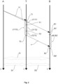
- FIG. 2 shows the flowchart of a possible embodiment of the method according to the invention.
- the vertical axes depict the passing of time.
- figure 2 is a schematic view, which only serves for illustration, the transceiver device T and the devices A, B are not necessarily in the plane of figure 2 .
- the devices A, B are arranged at a known and preferably fixed distance D from each other.
- the devices A, B are in an absolute reference system, for example they are secured to a building.
- the transceiver device T is preferably movable as compared to the devices A, B, however, during the implementation of the method its distance D1 as compared to the device A and its distance D2 as compared to the device B are known.
- a fixed calibration point can be designated at the distances D1, D2 as compared to the devices A, B, and the transceiver device T to be calibrated is maintained at this fixed point in the course of the method.
- the determination of the delay constant ⁇ takes place in the following way.
- the values of the time intervals ⁇ T1'T2' and ⁇ B1'B2' and/or the data required to determine these are sent to the central IT unit 10 by means of the transceiver device T and the second calibration device B.
- identification data is also sent to the central IT unit 10, with the help of which it may be clearly determined which device T, B the time intervals originate from.
- the delay constant ⁇ is determined by means of the central IT unit 10 on the basis of the distances D, D1, D2, the speed of propagation c of the wave signals and the time intervals ⁇ B1'B2', ⁇ T1'T2'.
- Figure 3 depicts the flowchart of another, preferable embodiment of the method according to the invention. This embodiment differs from that presented above in that in this case the first calibration device A is established to be capable of both generating and emitting electromagnetic wave signals. After the first calibration wave signal k1 has been emitted a second calibration wave signal k2 is emitted by means of the first calibration device A, which is detected by the transceiver device T. Through this the error originating from the measurement of time is reduced, thereby enabling the calibration to be more precise.
- the steps of the method presented in figure 3 are as follows.
- the response wave signal v emitted by the transceiver device T at time instance T2 is detected by means of the first calibration device A, then a second calibration wave signal k2 is emitted by means of the first calibration device A.
- the wave signal k2 emitted by the first calibration device A is detected by the transceiver device T at time instance T3'. Following this the time interval ⁇ T2'T3' passing between the time instances T2', T3' is determined, for example, in the way previously presented.
- the second calibration wave signal k2 reaches the device B at time instance B3, then the wave signal k2 is detected by means of the second calibration device B at time instance B3' following time instance B2' by the time interval ⁇ B2'B3' and the time interval ⁇ B2'B3' is determined.
- wave signals are both detected and emitted by the device A
- the transmission and receipt delays of the device A do not have to be taken into consideration during the method according to the invention, as time differences are not measured with the device A. To put it another way, device A does not have to be calibrated.
- the devices A, B similarly to the transceiver device T, are established so as to be capable of generating and emitting electromagnetic wave signals, and also capable of detecting electromagnetic wave signals.
- the devices A and B may be calibrated with the method according to the invention by the devices A, B and the transceiver device T swapping their roles.
- the method according to the invention is implemented in such a way as if the device A were the transceiver device T, and the transceiver device T were the device A.
- the method according to the invention is performed in such a way as if the device B were the transceiver device T, and the transceiver device T were the device B. Therefore, in the case of this embodiment by implementing the method according to the invention on all three of the devices T, A and B one after the other, the sums of the transmission and receipt delays may be determined for all three devices T, A, B, therefore each of the devices T, A, B may be calibrated.
- the object of the invention also relates to a system 100 for the implementation of the method according to the invention.
- the system 100 contains a transceiver device T, a first calibration device A suitable for generating and emitting electromagnetic wave signals arranged at a distance D1 from the transceiver device T, and a second calibration device B suitable for detecting electromagnetic wave signals arranged at a distance D2 from the transceiver device T and at a distance D from the first calibration device A.
- the system 100 also includes a central IT unit 10 in wired and/or wireless connection with the transceiver device T, and at least with the second calibration device B among the calibration devices A, B.
- a central IT unit 10 in wired and/or wireless connection with the transceiver device T, and at least with the second calibration device B among the calibration devices A, B.
Landscapes
- Engineering & Computer Science (AREA)
- Physics & Mathematics (AREA)
- Computer Networks & Wireless Communication (AREA)
- General Physics & Mathematics (AREA)
- Radar, Positioning & Navigation (AREA)
- Remote Sensing (AREA)
- Electromagnetism (AREA)
- Signal Processing (AREA)
- Radar Systems Or Details Thereof (AREA)
Claims (8)
- Verfahren zum Kalibrieren einer Transceivervorrichtung (T), die eingerichtet ist zum Erzeugen, Emittieren und Detektieren elektromagnetischer Wellensignale, charakterisiert durch- Bereitstellen einer ersten Kalibriervorrichtung (A), die eingerichtet ist zum Erzeugen und Emittieren elektromagnetischer Wellensignale, die in einer Distanz (D1) von der Transceivervorrichtung (T) angeordnet ist, und- Bereitstellen einer zweiten Kalibriervorrichtung (B), die eingerichtet ist zum Detektieren elektromagnetischer Wellensignale, die in einer Distanz (D2) von der Transceivervorrichtung (T) und in einer Distanz (D) von der ersten Kalibriervorrichtung (A) angeordnet ist,- Emittieren eines ersten Kalibrierwellensignals (k1) unter Verwendung der ersten Kalibriervorrichtung (A),- Detektieren des ersten Kalibrierwellensignals (k1), das die Transceivervorrichtung (T) in einer Zeitinstanz T1 erreicht, mittels der Transceivervorrichtung (T) in einer Zeitinstanz T1', die auf die Zeitinstanz T1 nach einem Zeitintervall ΔT1T1' folgt,- Detektieren des ersten Kalibrierwellensignals (k1) in einer Zeitinstanz B1' mittels der zweiten Kalibriervorrichtung (B),- Erzeugen eines Antwortwellensignals (v) mittels der Transceivervorrichtung (T) in einer Zeitinstanz T2', die auf die Zeitinstanz T1' nach einem Zeitintervall ΔT1'T2' folgt, und Emittieren des Antwortwellensignals (v) in Zeitinstanz T2, die auf die Zeitinstanz T2' nach einem Zeitintervall ΔT2'T2 folgt,- Detektieren des Antwortwellensignals (v), das von der Transceivervorrichtung (T) in der Zeitinstanz T2 emittiert wurde, in einer Zeitinstanz B2', die auf die Zeitinstanz B1' nach einem Zeitintervall ΔB1'B2' folgt, mittels der zweiten Kalibriervorrichtung (B), dann- Bestimmen einer Verzögerungskonstante τ, die als Summe der Zeitintervalle ΔT1T1' und ΔT2'T2 anhand der Distanzen D, D1, D2, der Zeitintervalle ΔB1'B2', ΔT1'T2' und der Ausbreitungsgeschwindigkeit (c) der Wellensignale (k1, v) unter Verwendung der Gleichung

- Verfahren nach Anspruch 1, charakterisiert dadurch, dass die erste Kalibriervorrichtung (A) auch zum Detektieren elektromagnetischer Wellensignale bereitgestellt wird und das Verfahren weiter umfasst:- Detektieren des Antwortsignals (v), das in der Zeitinstanz T2 von der Transceivervorrichtung (T) emittiert wurde, mittels der ersten Kalibriervorrichtung (A), dann Emittieren eines zweiten Kalibrierwellensignals (k2) mittels der ersten Kalibriervorrichtung (A),- Detektieren des zweiten Kalibrierwellensignals (k2), das von der ersten Kalibriervorrichtung (A) emittiert wurde, in der Zeitinstanz T3' mittels der Transceivervorrichtung (T),- außerdem Detektieren des zweien Kalibrierwellensignals (k2) in einer Zeitinstanz B3', die auf die Zeitinstanz B2' nach einem Zeitintervall ΔB2'B3' folgt, mittels der zweiten Kalibriervorrichtung (B), dann- Bestimmen der Verzögerungskonstante τ, die als eine Summe der Zeitintervalle ΔT1T1' und ΔT2'T2 anhand der Distanzen D, D1, D2, der Zeitintervalle ΔB1'B2', ΔT1'T2', ΔT2'T3', ΔB2'B3' und der Ausbreitungsgeschwindigkeit (c) der Wellensignale (k1, k2, v) gebildet wird unter Verwendung der Gleichung

- Verfahren nach Anspruch 1 oder 2, charakterisiert durch Bereitstellen einer zentralen IT-Einheit (10), die mit der Transceivervorrichtung (T) und wenigstens der zweiten Kalibriervorrichtung (B) aus den Kalibriervorrichtungen (A, B) mittels eines digitalen Kommunikationskanals (20) verbunden ist, Senden der Werte der Zeitintervalle ΔB1'B2', ΔT1'T2' und/oder der Daten, die zu deren Bestimmen benötigt werden, durch die Transceivervorrichtung (T) und die zweite Kalibriervorrichtung (B) an die zentrale IT-Einheit (10) über den digitalen Kommunikationskanal (20), und Bestimmen der Verzögerungskonstante τ anhand der Distanzen D, D1, D2, der Ausbreitungsgeschwindigkeit (c) der Wellensignale (k1, k2, v) und der Zeitintervalle ΔB1'B2', ΔT1'T2' mittels der zentralen IT-Einheit (10).
- Verfahren nach einem der Ansprüche 1 bis 3, charakterisiert dadurch, dass die elektromagnetischen Wellensignale (k1, k2, v) Ultrabreitbandsignale sind.
- Verfahren nach Anspruch 4, charakterisiert dadurch, dass die Zentralfrequenz und Bandbreite der Ultrabreitbandradiosignale im Gigahertzbereich liegen.
- Verfahren nach einem der Ansprüche 1 bis 5, charakterisiert dadurch, dass die zweite Kalibriervorrichtung (B) eingerichtet ist zum Erzeugen und Emittieren elektromagnetischer Wellensignale, und ferner zum Detektieren elektromagnetischer Wellensignale.
- System (100) zum Kalibrieren einer Transceivervorrichtung (T), die eingerichtet ist zum Erzeugen und Emittieren elektromagnetischer Wellensignale, und zum Detektieren elektromagnetischer Wellensignale, wobei das System (100) die Transceivervorrichtung (T), eine erste Kalibriervorrichtung (A), die eingerichtet ist zum Erzeugen und Emittieren elektromagnetischer Wellensignale, die in einer Distanz (D1) von der Transceivervorrichtung (T) angeordnet ist, und eine zweite Kalibriervorrichtung (B), die eingerichtet ist zum Detektieren elektromagnetischer Wellensignale, die in einer Distanz (D2) von der Transceivervorrichtung (T) und in einer Distanz (D) von der ersten Kalibriervorrichtung (A) angeordnet ist, umfasst, charakterisiert dadurch, dass die Transceivervorrichtung (T) und die ersten und zweiten Kalibriervorrichtungen (A, B) konfiguriert sind zum Ausführen des Verfahrens nach Ansprüchen 1 bis 6.
- System (100) nach Anspruch 7, charakterisiert dadurch, dass es eine zentrale IT-Einheit (10) in drahtgebundener und/oder drahtloser Verbindung mit der Transceivervorrichtung (T) und wenigstens mit der zweiten Kalibriervorrichtung (B) der Kalibriervorrichtungen (A, B) enthält.
Applications Claiming Priority (2)
| Application Number | Priority Date | Filing Date | Title |
|---|---|---|---|
| HUP1700379 HUP1700379A1 (hu) | 2017-09-11 | 2017-09-11 | Eljárás és rendszer adóvevõ eszköz kalibrálására |
| PCT/HU2018/050038 WO2019058150A1 (en) | 2017-09-11 | 2018-09-11 | TRANSMITTER-RECEIVER CALIBRATION METHOD AND SYSTEM |
Publications (4)
| Publication Number | Publication Date |
|---|---|
| EP3682259A1 EP3682259A1 (de) | 2020-07-22 |
| EP3682259A4 EP3682259A4 (de) | 2021-06-09 |
| EP3682259B1 true EP3682259B1 (de) | 2023-11-08 |
| EP3682259C0 EP3682259C0 (de) | 2023-11-08 |
Family
ID=89992526
Family Applications (1)
| Application Number | Title | Priority Date | Filing Date |
|---|---|---|---|
| EP18859147.3A Active EP3682259B1 (de) | 2017-09-11 | 2018-09-11 | Verfahren und system zur kalibrierung von sender-empfängern |
Country Status (4)
| Country | Link |
|---|---|
| US (1) | US11269039B2 (de) |
| EP (1) | EP3682259B1 (de) |
| HU (2) | HUP1700379A1 (de) |
| WO (1) | WO2019058150A1 (de) |
Families Citing this family (2)
| Publication number | Priority date | Publication date | Assignee | Title |
|---|---|---|---|---|
| CN114071692B (zh) | 2020-08-07 | 2023-08-01 | 大唐移动通信设备有限公司 | 发送通道时延的校正方法、装置及存储介质 |
| CN114339599B (zh) * | 2021-12-31 | 2024-06-28 | 中国电信股份有限公司 | 定位校准方法、定位方法、装置、存储介质和电子设备 |
Family Cites Families (6)
| Publication number | Priority date | Publication date | Assignee | Title |
|---|---|---|---|---|
| EP1377946A1 (de) * | 2001-03-12 | 2004-01-07 | Eureka Technologies Partners, LLc | Objektpositionsbestimmungssystem |
| US20050129139A1 (en) * | 2003-12-03 | 2005-06-16 | Jones Aled W. | Tag tracking |
| US7492316B1 (en) * | 2005-12-23 | 2009-02-17 | Multispectral Solutions, Inc. | Wireless time reference system and method |
| US20100135178A1 (en) * | 2008-11-21 | 2010-06-03 | Qualcomm Incorporated | Wireless position determination using adjusted round trip time measurements |
| EP2244098B1 (de) | 2009-04-20 | 2011-10-26 | Universität Duisburg-Essen | Master-Sende-Empfangsgerät und Slave-Sende-Empfangsgerät zur Bestimmung von Bereichsinformation |
| EP3268765B1 (de) * | 2015-03-07 | 2024-01-17 | Verity AG | Systeme und verfahren zur verteilten lokalisierung und selbstlokalisierungsvorrichtung |
-
2017
- 2017-09-11 HU HUP1700379 patent/HUP1700379A1/hu unknown
-
2018
- 2018-09-11 US US16/645,921 patent/US11269039B2/en active Active
- 2018-09-11 WO PCT/HU2018/050038 patent/WO2019058150A1/en not_active Ceased
- 2018-09-11 HU HUE18859147A patent/HUE064827T2/hu unknown
- 2018-09-11 EP EP18859147.3A patent/EP3682259B1/de active Active
Also Published As
| Publication number | Publication date |
|---|---|
| US20200278415A1 (en) | 2020-09-03 |
| WO2019058150A1 (en) | 2019-03-28 |
| US11269039B2 (en) | 2022-03-08 |
| EP3682259A4 (de) | 2021-06-09 |
| HUP1700379A1 (hu) | 2019-04-29 |
| EP3682259A1 (de) | 2020-07-22 |
| EP3682259C0 (de) | 2023-11-08 |
| HUE064827T2 (hu) | 2024-04-28 |
Similar Documents
| Publication | Publication Date | Title |
|---|---|---|
| US12000948B2 (en) | Positioning system | |
| US20250321315A1 (en) | Method and system for multipath reduction for wireless synchronization and/or locating | |
| CN113625263B (zh) | 定位系统 | |
| AU2020233659B2 (en) | Positioning system | |
| US8335173B2 (en) | Inserting time of departure information in frames to support multi-channel location techniques | |
| US11102746B2 (en) | Positioning system | |
| US20040108954A1 (en) | Object location system and method | |
| EP3544323A1 (de) | Verfahren zur bestimmung der kanalzeitverzögerung, positionierungsverfahren und zugehörige vorrichtung | |
| KR101836837B1 (ko) | 측위 시스템 내 시간 차이 보상 방법 및 그에 따른 측위 시스템 | |
| US20130241774A1 (en) | Wireless positioning server using clock offset calibration and wireless positioning method using the same | |
| US9952308B2 (en) | Access point, terminal, and wireless fidelity WiFi indoor positioning method | |
| EP3682259B1 (de) | Verfahren und system zur kalibrierung von sender-empfängern | |
| Horváth et al. | Calibration method of antenna delays for UWB-based localization systems | |
| JP6573328B2 (ja) | 無線通信システム及び無線通信装置 | |
| HU231576B1 (hu) | Eljárás és rendszer távolságmérésre hullámjelek segítségével |
Legal Events
| Date | Code | Title | Description |
|---|---|---|---|
| STAA | Information on the status of an ep patent application or granted ep patent |
Free format text: STATUS: THE INTERNATIONAL PUBLICATION HAS BEEN MADE |
|
| PUAI | Public reference made under article 153(3) epc to a published international application that has entered the european phase |
Free format text: ORIGINAL CODE: 0009012 |
|
| STAA | Information on the status of an ep patent application or granted ep patent |
Free format text: STATUS: REQUEST FOR EXAMINATION WAS MADE |
|
| 17P | Request for examination filed |
Effective date: 20200324 |
|
| AK | Designated contracting states |
Kind code of ref document: A1 Designated state(s): AL AT BE BG CH CY CZ DE DK EE ES FI FR GB GR HR HU IE IS IT LI LT LU LV MC MK MT NL NO PL PT RO RS SE SI SK SM TR |
|
| AX | Request for extension of the european patent |
Extension state: BA ME |
|
| RAV | Requested validation state of the european patent: fee paid |
Extension state: MD Effective date: 20200324 |
|
| A4 | Supplementary search report drawn up and despatched |
Effective date: 20210511 |
|
| RIC1 | Information provided on ipc code assigned before grant |
Ipc: G01S 1/20 20060101AFI20210505BHEP Ipc: G01S 5/10 20060101ALI20210505BHEP Ipc: G01S 1/02 20100101ALI20210505BHEP Ipc: G01S 5/02 20100101ALI20210505BHEP |
|
| GRAP | Despatch of communication of intention to grant a patent |
Free format text: ORIGINAL CODE: EPIDOSNIGR1 |
|
| STAA | Information on the status of an ep patent application or granted ep patent |
Free format text: STATUS: GRANT OF PATENT IS INTENDED |
|
| RIN1 | Information on inventor provided before grant (corrected) |
Inventor name: MILANKOVICH, AKOS Inventor name: ILL, GERGELY Inventor name: HORVATH, KRISTOF ATTILA Inventor name: SZABO, SANDOR Inventor name: LENDVAI, KAROLY Inventor name: BALOGH, ANDRAS |
|
| INTG | Intention to grant announced |
Effective date: 20230221 |
|
| GRAS | Grant fee paid |
Free format text: ORIGINAL CODE: EPIDOSNIGR3 |
|
| GRAJ | Information related to disapproval of communication of intention to grant by the applicant or resumption of examination proceedings by the epo deleted |
Free format text: ORIGINAL CODE: EPIDOSDIGR1 |
|
| GRAL | Information related to payment of fee for publishing/printing deleted |
Free format text: ORIGINAL CODE: EPIDOSDIGR3 |
|
| STAA | Information on the status of an ep patent application or granted ep patent |
Free format text: STATUS: REQUEST FOR EXAMINATION WAS MADE |
|
| GRAP | Despatch of communication of intention to grant a patent |
Free format text: ORIGINAL CODE: EPIDOSNIGR1 |
|
| STAA | Information on the status of an ep patent application or granted ep patent |
Free format text: STATUS: GRANT OF PATENT IS INTENDED |
|
| INTC | Intention to grant announced (deleted) | ||
| INTG | Intention to grant announced |
Effective date: 20230718 |
|
| GRAA | (expected) grant |
Free format text: ORIGINAL CODE: 0009210 |
|
| STAA | Information on the status of an ep patent application or granted ep patent |
Free format text: STATUS: THE PATENT HAS BEEN GRANTED |
|
| AK | Designated contracting states |
Kind code of ref document: B1 Designated state(s): AL AT BE BG CH CY CZ DE DK EE ES FI FR GB GR HR HU IE IS IT LI LT LU LV MC MK MT NL NO PL PT RO RS SE SI SK SM TR |
|
| REG | Reference to a national code |
Ref country code: GB Ref legal event code: FG4D |
|
| REG | Reference to a national code |
Ref country code: CH Ref legal event code: EP |
|
| REG | Reference to a national code |
Ref country code: DE Ref legal event code: R096 Ref document number: 602018060956 Country of ref document: DE |
|
| REG | Reference to a national code |
Ref country code: IE Ref legal event code: FG4D |
|
| U01 | Request for unitary effect filed |
Effective date: 20231121 |
|
| U07 | Unitary effect registered |
Designated state(s): AT BE BG DE DK EE FI FR IT LT LU LV MT NL PT SE SI Effective date: 20231127 |
|
| REG | Reference to a national code |
Ref country code: HU Ref legal event code: HC9C Owner name: POZI DEVELOPMENT KFT., HU Free format text: FORMER OWNER(S): POZI DEVELOPMENT KFT., HU |
|
| PG25 | Lapsed in a contracting state [announced via postgrant information from national office to epo] |
Ref country code: GR Free format text: LAPSE BECAUSE OF FAILURE TO SUBMIT A TRANSLATION OF THE DESCRIPTION OR TO PAY THE FEE WITHIN THE PRESCRIBED TIME-LIMIT Effective date: 20240209 |
|
| PG25 | Lapsed in a contracting state [announced via postgrant information from national office to epo] |
Ref country code: IS Free format text: LAPSE BECAUSE OF FAILURE TO SUBMIT A TRANSLATION OF THE DESCRIPTION OR TO PAY THE FEE WITHIN THE PRESCRIBED TIME-LIMIT Effective date: 20240308 |
|
| PG25 | Lapsed in a contracting state [announced via postgrant information from national office to epo] |
Ref country code: ES Free format text: LAPSE BECAUSE OF FAILURE TO SUBMIT A TRANSLATION OF THE DESCRIPTION OR TO PAY THE FEE WITHIN THE PRESCRIBED TIME-LIMIT Effective date: 20231108 |
|
| REG | Reference to a national code |
Ref country code: HU Ref legal event code: AG4A Ref document number: E064827 Country of ref document: HU |
|
| PG25 | Lapsed in a contracting state [announced via postgrant information from national office to epo] |
Ref country code: IS Free format text: LAPSE BECAUSE OF FAILURE TO SUBMIT A TRANSLATION OF THE DESCRIPTION OR TO PAY THE FEE WITHIN THE PRESCRIBED TIME-LIMIT Effective date: 20240308 Ref country code: GR Free format text: LAPSE BECAUSE OF FAILURE TO SUBMIT A TRANSLATION OF THE DESCRIPTION OR TO PAY THE FEE WITHIN THE PRESCRIBED TIME-LIMIT Effective date: 20240209 Ref country code: ES Free format text: LAPSE BECAUSE OF FAILURE TO SUBMIT A TRANSLATION OF THE DESCRIPTION OR TO PAY THE FEE WITHIN THE PRESCRIBED TIME-LIMIT Effective date: 20231108 |
|
| PG25 | Lapsed in a contracting state [announced via postgrant information from national office to epo] |
Ref country code: RS Free format text: LAPSE BECAUSE OF FAILURE TO SUBMIT A TRANSLATION OF THE DESCRIPTION OR TO PAY THE FEE WITHIN THE PRESCRIBED TIME-LIMIT Effective date: 20231108 Ref country code: PL Free format text: LAPSE BECAUSE OF FAILURE TO SUBMIT A TRANSLATION OF THE DESCRIPTION OR TO PAY THE FEE WITHIN THE PRESCRIBED TIME-LIMIT Effective date: 20231108 Ref country code: NO Free format text: LAPSE BECAUSE OF FAILURE TO SUBMIT A TRANSLATION OF THE DESCRIPTION OR TO PAY THE FEE WITHIN THE PRESCRIBED TIME-LIMIT Effective date: 20240208 Ref country code: HR Free format text: LAPSE BECAUSE OF FAILURE TO SUBMIT A TRANSLATION OF THE DESCRIPTION OR TO PAY THE FEE WITHIN THE PRESCRIBED TIME-LIMIT Effective date: 20231108 |
|
| PG25 | Lapsed in a contracting state [announced via postgrant information from national office to epo] |
Ref country code: CZ Free format text: LAPSE BECAUSE OF FAILURE TO SUBMIT A TRANSLATION OF THE DESCRIPTION OR TO PAY THE FEE WITHIN THE PRESCRIBED TIME-LIMIT Effective date: 20231108 |
|
| PG25 | Lapsed in a contracting state [announced via postgrant information from national office to epo] |
Ref country code: SK Free format text: LAPSE BECAUSE OF FAILURE TO SUBMIT A TRANSLATION OF THE DESCRIPTION OR TO PAY THE FEE WITHIN THE PRESCRIBED TIME-LIMIT Effective date: 20231108 |
|
| PG25 | Lapsed in a contracting state [announced via postgrant information from national office to epo] |
Ref country code: SM Free format text: LAPSE BECAUSE OF FAILURE TO SUBMIT A TRANSLATION OF THE DESCRIPTION OR TO PAY THE FEE WITHIN THE PRESCRIBED TIME-LIMIT Effective date: 20231108 Ref country code: SK Free format text: LAPSE BECAUSE OF FAILURE TO SUBMIT A TRANSLATION OF THE DESCRIPTION OR TO PAY THE FEE WITHIN THE PRESCRIBED TIME-LIMIT Effective date: 20231108 Ref country code: RO Free format text: LAPSE BECAUSE OF FAILURE TO SUBMIT A TRANSLATION OF THE DESCRIPTION OR TO PAY THE FEE WITHIN THE PRESCRIBED TIME-LIMIT Effective date: 20231108 Ref country code: CZ Free format text: LAPSE BECAUSE OF FAILURE TO SUBMIT A TRANSLATION OF THE DESCRIPTION OR TO PAY THE FEE WITHIN THE PRESCRIBED TIME-LIMIT Effective date: 20231108 |
|
| REG | Reference to a national code |
Ref country code: DE Ref legal event code: R097 Ref document number: 602018060956 Country of ref document: DE |
|
| PLBE | No opposition filed within time limit |
Free format text: ORIGINAL CODE: 0009261 |
|
| STAA | Information on the status of an ep patent application or granted ep patent |
Free format text: STATUS: NO OPPOSITION FILED WITHIN TIME LIMIT |
|
| VS25 | Lapsed in a validation state [announced via postgrant information from nat. office to epo] |
Ref country code: MD Free format text: LAPSE BECAUSE OF FAILURE TO SUBMIT A TRANSLATION OF THE DESCRIPTION OR TO PAY THE FEE WITHIN THE PRESCRIBED TIME-LIMIT Effective date: 20231108 |
|
| 26N | No opposition filed |
Effective date: 20240809 |
|
| U20 | Renewal fee for the european patent with unitary effect paid |
Year of fee payment: 7 Effective date: 20240912 |
|
| PG25 | Lapsed in a contracting state [announced via postgrant information from national office to epo] |
Ref country code: MC Free format text: LAPSE BECAUSE OF FAILURE TO SUBMIT A TRANSLATION OF THE DESCRIPTION OR TO PAY THE FEE WITHIN THE PRESCRIBED TIME-LIMIT Effective date: 20231108 |
|
| REG | Reference to a national code |
Ref country code: CH Ref legal event code: PL |
|
| GBPC | Gb: european patent ceased through non-payment of renewal fee |
Effective date: 20240911 |
|
| PG25 | Lapsed in a contracting state [announced via postgrant information from national office to epo] |
Ref country code: GB Free format text: LAPSE BECAUSE OF NON-PAYMENT OF DUE FEES Effective date: 20240911 |
|
| PG25 | Lapsed in a contracting state [announced via postgrant information from national office to epo] |
Ref country code: CH Free format text: LAPSE BECAUSE OF NON-PAYMENT OF DUE FEES Effective date: 20240930 |
|
| PG25 | Lapsed in a contracting state [announced via postgrant information from national office to epo] |
Ref country code: IE Free format text: LAPSE BECAUSE OF NON-PAYMENT OF DUE FEES Effective date: 20240911 |
|
| PGFP | Annual fee paid to national office [announced via postgrant information from national office to epo] |
Ref country code: HU Payment date: 20250926 Year of fee payment: 8 |
|
| U20 | Renewal fee for the european patent with unitary effect paid |
Year of fee payment: 8 Effective date: 20250919 |
|
| PG25 | Lapsed in a contracting state [announced via postgrant information from national office to epo] |
Ref country code: CY Free format text: LAPSE BECAUSE OF FAILURE TO SUBMIT A TRANSLATION OF THE DESCRIPTION OR TO PAY THE FEE WITHIN THE PRESCRIBED TIME-LIMIT; INVALID AB INITIO Effective date: 20180911 |