EP3682736A1 - Hundetoilette - Google Patents
Hundetoilette Download PDFInfo
- Publication number
- EP3682736A1 EP3682736A1 EP18892937.6A EP18892937A EP3682736A1 EP 3682736 A1 EP3682736 A1 EP 3682736A1 EP 18892937 A EP18892937 A EP 18892937A EP 3682736 A1 EP3682736 A1 EP 3682736A1
- Authority
- EP
- European Patent Office
- Prior art keywords
- dog
- wall portion
- toilet
- area
- dog toilet
- Prior art date
- Legal status (The legal status is an assumption and is not a legal conclusion. Google has not performed a legal analysis and makes no representation as to the accuracy of the status listed.)
- Granted
Links
Images




Classifications
-
- A—HUMAN NECESSITIES
- A01—AGRICULTURE; FORESTRY; ANIMAL HUSBANDRY; HUNTING; TRAPPING; FISHING
- A01K—ANIMAL HUSBANDRY; AVICULTURE; APICULTURE; PISCICULTURE; FISHING; REARING OR BREEDING ANIMALS, NOT OTHERWISE PROVIDED FOR; NEW BREEDS OF ANIMALS
- A01K1/00—Housing animals; Equipment therefor
- A01K1/01—Removal of dung or urine ; Removal of manure from stables
-
- A—HUMAN NECESSITIES
- A01—AGRICULTURE; FORESTRY; ANIMAL HUSBANDRY; HUNTING; TRAPPING; FISHING
- A01K—ANIMAL HUSBANDRY; AVICULTURE; APICULTURE; PISCICULTURE; FISHING; REARING OR BREEDING ANIMALS, NOT OTHERWISE PROVIDED FOR; NEW BREEDS OF ANIMALS
- A01K1/00—Housing animals; Equipment therefor
- A01K1/01—Removal of dung or urine ; Removal of manure from stables
- A01K1/0107—Cat trays; Dog urinals; Toilets for pets
-
- A—HUMAN NECESSITIES
- A01—AGRICULTURE; FORESTRY; ANIMAL HUSBANDRY; HUNTING; TRAPPING; FISHING
- A01K—ANIMAL HUSBANDRY; AVICULTURE; APICULTURE; PISCICULTURE; FISHING; REARING OR BREEDING ANIMALS, NOT OTHERWISE PROVIDED FOR; NEW BREEDS OF ANIMALS
- A01K29/00—Other apparatus for animal husbandry
- A01K29/005—Monitoring or measuring activity
-
- A—HUMAN NECESSITIES
- A01—AGRICULTURE; FORESTRY; ANIMAL HUSBANDRY; HUNTING; TRAPPING; FISHING
- A01K—ANIMAL HUSBANDRY; AVICULTURE; APICULTURE; PISCICULTURE; FISHING; REARING OR BREEDING ANIMALS, NOT OTHERWISE PROVIDED FOR; NEW BREEDS OF ANIMALS
- A01K5/00—Feeding devices for stock or game ; Feeding wagons; Feeding stacks
- A01K5/02—Automatic devices
Definitions
- the present invention relates to a dog toilet.
- a toilet described in Patent Literature 1 includes: a urination detection sensor provided in a bottom portion; and a feeder that operates on the basis of a detection result of the urination detection sensor. When an animal excretes in the toilet, the urination detection sensor detects urine, and food is supplied from the feeder.
- Patent Literature 1 Japanese Patent Application Publication No. 2009-45053
- the present invention was achieved in light of conventional problems such as that described above, and an aspect of the present invention is to provide a dog toilet capable of preventing an area outside a toilet from being soiled with urine.
- a main aspect of the present invention for achieving the above-described aspect is a dog toilet having a front-rear direction, a left-right direction, and an up-down direction that are perpendicular to one another, the dog toilet including:
- a dog toilet having a front-rear direction, a left-right direction, and an up-down direction that are perpendicular to one another, the dog toilet including:
- the wall portion is a continuous plate-shaped wall.
- the wall portion includes:
- a continuous convex member is arranged between an excretion area of the dog and a feeding area where the food is supplied.
- a continuous concave groove is formed between an excretion area of the dog and a feeding area where the food is supplied.
- a liquid-absorbent absorbent member that absorbs urine is arranged in the bottom portion, and an area of a portion of the absorbent member located on the other side in the front-rear direction is larger than an area of a portion of the absorbent member located on the one side in the front-rear direction.
- the bottom portion is provided with a protruding portion that surrounds the absorbent member.
- the feeding port is arranged in a corner portion, and the corner portion is constituted by a portion of the wall portion on the other side in the front-rear direction and a portion of the wall portion on either one of sides in the left-right direction.
- the feeder is provided outside the wall portion.
- the access opening is provided with a door, and the door is an automatically opening and closing door that opens after a predetermined period passes since the urination detection sensor detects urination by the dog.
- the feeding port is provided on one side in the left-right direction with respect to a left-right-direction center position, and the access opening is provided on another side in the left-right direction with respect to the left-right-direction center position.
- the feeding port and the access opening are provided on an identical side in the left-right direction with respect to a left-right-direction center position.
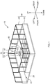
- FIG. 1 is a schematic perspective view of the dog toilet 10.
- FIG. 2 is a plan view of the dog toilet 10 viewed from above.
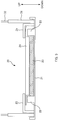
- FIG. 3 is a sectional view illustrating an example of a configuration of a bottom portion 20.
- FIG. 4A is a sectional view illustrating an arrangement of individual electrodes (a positive electrode 41 and a negative electrode 42) in the bottom portion 20.
- FIG. 4B is a plan view of a portion around a grate 24 viewed from above
- FIG. 4C is a perspective view of FIG. 4B
- FIG. 4D is a sectional view. Note that, in FIG.
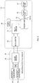
- FIG. 5 is a block diagram illustrating configurations of a urination detection sensor 40 and a feeder unit 50.
- the dog toilet 10 is a toilet capable of being used for toilet-training a dog and is placed on the floor or the like for use.
- front-rear direction "left-right direction”, and "up-down direction”, which denote three directions perpendicular to one another, are defined as illustrated in FIG. 1 .
- the up-down direction is the vertical direction.
- a placement surface (a bottom surface of a bottom-portion main body 21) side is denoted as "lower side”, and the opposite side is denoted as "upper side”.
- the front-rear direction and the left-right direction denote directions of a horizontal plane (horizontal direction).
- a central position in the front-rear direction is denoted as a center position C1.
- a side where an access opening 33 is provided relative to the center position C1 is denoted as "front side”, and the opposite side is denoted as “rear side”.
- a central position in the left-right direction is denoted as a center position C2.
- a side where the access opening 33 is provided relative to the center position C2 is denoted as "left side”, and the opposite side is denoted as "right side”.
- the dog toilet 10 includes the bottom portion 20, a wall portion 30, the urination detection sensor 40, and the feeder unit 50.
- the bottom portion 20 has a rectangular shape in plan view, and respective sides of the bottom portion 20 extend in the front-rear direction and the left-right direction.
- the bottom portion 20 includes the bottom-portion main body 21, a protruding portion 22, an absorption sheet 23 (corresponding to an absorbent member), the grate 24 (corresponding to an insulating member and a liquid-permeable layer), and a cover 25.
- the bottom-portion main body 21 is the lowest portion (base) of the bottom portion 20 and is a portion that constitutes a toilet structure.
- An area surrounded by the protruding portion 22 in the bottom-portion main body 21 is an area where a dog excretes. In the following description, this area is also referred to as an excretion area.
- the protruding portion 22 is a portion that protrudes upward from the bottom-portion main body 21 and is provided so as to surround the absorption sheet 23.
- the bottom-portion main body 21 is provided with the protruding portion 22 in this manner, and the absorption sheet 23 is arranged inside the protruding portion 22. Consequently, the absorption sheet 23 is less likely to be displaced (the absorption sheet 23 is less likely to be moved) even if the dog walks around, for example.
- the absorption sheet 23 is a liquid-absorbent sheet member that absorbs urine or the like excreted by an animal (herein, a dog), and the absorption sheet 23 includes a liquid absorbent material (corresponding to an absorbent body) such as pulp fiber or superabsorbent polymer.
- the absorption sheet 23 contains deodorant microcapsules and an antibacterial agent, masking the smell of absorbed urine and suppressing the propagation of bacteria from occurring.
- the absorption sheet 23 is arranged in the excretion area (the area surrounded by the protruding portion 22 in the bottom-portion main body 21). As a result of the absorption sheet 23 being arranged in the excretion area in this manner, urine is absorbed by the absorption sheet 23. This makes it possible to suppress erroneous operation of the urination detection sensor 40 and a feeder 52 due to dispersal of urine caused by vibration that occurs when the dog moves around wildly, for example.
- the absorption sheet 23 (as well as the grate 24) is arranged to be lopsided with respect to the center position C1 in the front-rear direction. Specifically, the absorption sheet 23 is arranged such that the area of a portion on the rear side with respect to the center position C1 is larger than the area of a portion on the front side with respect to the center position C1 (see FIG. 2 ). This is because the possibility of the dog approaching a feeding plate 51 is high because of the smell of food remaining in the feeding plate 51 when the dog enters the dog toilet 10, and therefore the possibility of the dog urinating on the rear side relative to the center position C1 is high. Thus, making the area of the rear-side (feeding-plate-51-side) portion larger than the area of the front-side (access-opening-33-side) portion relative to the center position C1 makes it possible for the absorption sheet 23 to be arranged efficiently.
- the grate 24 is arranged so as to cover the absorption sheet 23 (that is, in the excretion area).
- the grate 24 has the plurality of apertures 24a penetrating in the up-down direction and enables urine or the like excreted by the dog to pass through the apertures 24a from the upper side to the lower side (toward the absorption sheet 23) in the up-down direction. That is, the grate 24 corresponds to a liquid-permeable layer.
- the grate 24 in the present embodiment is formed into a rectangular grating shape, and the apertures 24a each have a rectangular shape in plan view. However, the configuration is not limited to this, and a grate having circular or hexagonal apertures may be used.
- the positive electrode 41 and the negative electrode 42 of the urination detection sensor 40 are arranged on the grate 24.
- an insulator particularly, a non-liquid-absorbent insulator that does not absorb liquid (for example, polypropylene, silicone, or the like) is used.
- a non-liquid-absorbent insulator that does not absorb liquid
- an absorbent insulator for example, sponge
- the insulator absorbs urine.
- the absorbed urine causes the positive electrode 41 and the negative electrode 42 to continue conducting electricity, which hinders accurate determination.
- That the grate 24 is composed of a non-liquid-absorbent insulator makes it less likely for the grate 24 to hold urine. This makes it possible to prevent the positive electrode 41 and the negative electrode 42 from continuing conducting electricity.
- a hydrophobic material having a surface that increases surface tension is preferably used.
- the cover 25 is attached above the bottom-portion main body 21 and covers the bottom-portion main body 21 and the protruding portion 22.
- the cover 25 has an opening in a portion corresponding to the position where the absorption sheet 23 is arranged (the excretion area). Consequently, the cover 25 constitutes an upper surface of the bottom portion 20 except for the excretion area.
- the grate 24 is suspended on the cover 25 in such a manner to move in the up-down direction.
- the wall portion 30 is provided so as to surround the four sides of the bottom portion 20 (in the front-rear direction and the left-right direction) .
- an inner side of the wall portion 30 is also referred to as inside the toilet.
- the wall portion 30 in the present embodiment includes a plate wall 31 (corresponding to a first wall portion), a fence 32 (corresponding to a second wall portion), and the access opening 33.
- the plate wall 31 is a plate-shaped wall that is continuous and is erected on the bottom portion 20.
- the plate wall 31 illustrated in FIG. 3 has side faces that are perpendicular to the horizontal plane and that have a constant thickness irrespective of the position in the up-down direction.
- the configuration of the plate wall 31 is not limited to this.
- the plate wall 31 may be an inclined surface having a thickness that decreases from the lower side to the upper side in the up-down direction.
- the plate wall 31 may be an inclined surface having a thickness that increases from the lower side to the upper side in the up-down direction.
- the fence 32 is a mesh-like barrier having voids and is provided above the plate wall 31.
- the wall portion 30 of the dog toilet 10 has a combined configuration of the plate wall 31 and the fence 32.
- the plate wall 31 constitutes the lower portion of the wall portion 30, and this ensures that food or urine of the dog are less likely to spill to an area outside the toilet.
- the fence 32 constitutes the upper portion of the wall portion 30, and this enables the dog to have good visibility, making it more likely for the dog to urinate in the toilet without any stress.
- a feeding tube 53 is easily drawn through the wall portion 30 to the inner side of the wall portion 30. Note that as materials of the plate wall 31 and the fence 32, any material, such as metal, plastic, or wood, may be used.
- the access opening 33 is a portion where the dog enters and exits the toilet (the inner side of the wall portion 30) and is formed at the left end of a portion (front-side portion) of the wall portion 30 that demarcates the front side of the bottom portion 20. That is, the access opening 33 is provided on the front side relative to the center position C1 in the front-rear direction and on the left side relative to the center position C2 in the left-right direction.
- the access opening 33 in the present embodiment is formed by making an opening at the above-described portion of the wall portion 30 (the plate wall 31 and the fence 32) surrounding the bottom portion 20 (making the above-described portion discontinuous).
- the urination detection sensor 40 is a sensor that detects whether there is urination by a dog (specifically, the presence of liquid) .
- the urination detection sensor 40 includes the positive electrode 41, the negative electrode 42, and a liquid sensor 43.
- the positive electrode 41 is arranged on (the upper surface of) the grate 24.
- a material of the positive electrode 41 a material having high conductivity (for example, copper or rust-resistant stainless steel) is preferable.
- the negative electrode 42 is also formed of a material having high conductivity, similarly to the positive electrode 41, and is arranged under (on the lower surface of) the grate 24.
- the positive electrode 41 and the negative electrode 42 are provided on the grate 24 that covers the absorption sheet 23. This make urine be quickly absorbed by the absorption sheet 23, making it possible to reduce the amount of urine that remains on the electrodes. Consequently, it is possible to correctly detect the urination timing.
- the grate 24 and the individual electrodes (the positive electrode 41 and the negative electrode 42), and the negative electrode 42 and the absorption sheet 23 are illustrated as spaced apart from each other. However, they are actually in contact with each other.
- urine adhered to the negative electrode 42 can be absorbed by the absorption sheet 23. This can suppress, for example, the occurrence of the smell of urine.
- the grate 24 is suspended on the cover 25 to be vertically movable as described above, the negative electrode 42 is vertically movable together with the grate 24 even if the absorption sheet 23 expands due to absorbing urine.
- the positive electrode 41 is divided into a plurality of branches on the grate 24, and the plurality of branches are linearly arranged extending along the front-rear direction with spaces therebetween in the left-right direction to be parallel to one another.
- the negative electrode 42 is also divided into a plurality of branches on the grate 24, and the plurality of branches are linearly arranged extending along the front-rear direction with spaces therebetween in the left-right direction to be parallel to one another (to form pairs with the positive electrode 41).
- a plurality of pairs of the positive electrode 41 and the negative electrode 42 are arranged side-by-side in the horizontal direction (the left-right direction).
- the electrodes can be arranged densely, making it possible to increase the accuracy of the urination detection sensor 40.
- the positive electrode 41 and the negative electrode 42 forming a pair are spaced apart in the up-down direction and superpose in terms of position in the horizontal direction (the left-right direction herein).
- the positive electrode 41 is arranged on the grate 24 and the negative electrode 42 is arranged under the grate 24 in the present embodiment, the arrangement may be reversed. That is, the negative electrode 42 may be arranged on the grate 24 and the positive electrode 41 may be arranged under the grate 24.
- each of the positive electrode 41 and the negative electrode 42 that constitute a pair is linearly arranged along the front-rear direction in the present embodiment, the arrangement is not limited to this.
- each of the positive electrode 41 and the negative electrode 42 may be arranged in the left-right direction.
- each of the positive electrode 41 and the negative electrode 42 may be arranged to be bent in a zigzag shape on the horizontal plane in accordance with the shape of the grate 24.
- a distance d between the electrodes that are adjacent to each other in the horizontal direction may be arbitrary. However, since urine needs at least to be directly in contact with the electrodes, the distance is desirably 5 cm or less. In addition, if the distance is too short, it is difficult to remove feces soiling. Therefore, the distance is desirably 1 cm or greater.
- a width W2 of the grate 24 illustrated in FIG. 4D is greater than a width W1 of the positive electrode 41 and the negative electrode 42. This is because, if the width W2 of the grate 24 is less than the width W1 of the positive electrode 41 and the negative electrode 42, there is a risk that urine remains on a side wall of the grate 24 owing to surface tension of the urine and the conducting state continues, and decreases the accuracy of the urination detection sensor 40.
- the width W2 of the grate 24 is set greater than the width W1 of the positive electrode 41 and the negative electrode 42.
- the liquid sensor 43 amplifies an electric signal (voltage) when the positive electrode 41 and the negative electrode 42 conduct electricity, and outputs the amplified signal to a microcomputer 55.
- a method for controlling the liquid sensor 43 involves analog control using an analog voltage value.
- the control method is not limited to this, and digital control using H (high)/L (low) digital signals may be used.
- the feeder unit 50 includes the feeding plate 51, the feeder 52, the feeding tube 53, a power supply 54, the microcomputer 55, and a relay circuit 56.
- the feeding plate 51 is a container in which dog food is held.
- the feeding plate 51 includes a bottom wall 51a having a circular shape in plan view, and a peripheral side wall 51b that is erected upward on the periphery of the bottom wall 51a.
- the bottom wall 51a of the feeding plate 51 corresponds to a feeding area
- the peripheral side wall 51b corresponds to a convex member.
- the feeding plate 51 (in other words, the feeding port 53a) is arranged in a corner portion (that is, a corner portion on a left rear side in the wall portion 30), and this corner portion is formed by a portion of the wall portion 30 on the rear side in the front-rear direction and a portion of the wall portion 30 on the left side in the left-right direction. This can ensure a wide space (excretion area) in the toilet.
- the feeder 52 is an electrically powered apparatus (feeder) that automatically supplies food on the basis of a detection result of the urination detection sensor 40.
- the feeding tube 53 is attached to the feeder 52. Note that the feeder 52 is arranged outside the wall portion 30, and that the feeding tube 53 attached to the feeder 52 is drawn to the inner side of the wall portion 30 through the fence 32. The configuration of the feeder 52 will be described later.
- the feeding tube 53 is a hollow tubular member (for example, a tube) for supplying food ejected from the feeder 52 to the feeding plate 51, and the feeding tube 53 has the feeding port 53a.
- the feeding port 53a is an outlet of the feeding tube 53 and is arranged above the feeding plate 51 in the toilet. That is, the feeding port 53a is arranged on the rear side relative to the center position C1 in the front-rear direction.
- the feeding plate 51 is arranged on the rear side in the front-rear direction and the access opening 33 is provided in the wall portion 30 on the front side in the front-rear direction.
- the positions of the feeding port 53a and the access opening 33 are close to each other, there is a risk that the dog discharge residual urine in an area outside the toilet while eating food.
- the positions of the feeding port 53a and the access opening 33 are apart from each other. This makes it possible for the dog which is eating food to stay in the toilet after urination, making it possible to prevent an area outside the toilet from being soiled with urine.
- the power supply 54 supplies electric power to each of the components (the feeder 52, the microcomputer 55, and the relay circuit 56) of the feeder unit 50.
- the output of the urination detection sensor 40 (the liquid sensor 43) is input to the microcomputer 55.
- the microcomputer 55 performs control described below, in accordance with a change in voltage of the urination detection sensor 40. That is, when the voltage falls below a predetermined voltage (because the positive electrode 41 and the negative electrode 42 stop conducting electricity) after the voltage rises (because the positive electrode 41 and the negative electrode 42 conduct electricity), the microcomputer 55 causes the relay circuit 56 to operate.
- the relay circuit 56 operates (is active) for a certain period according to controlling of the time in seconds, and thereby the relay circuit 56 causes the feeder 52 to operate (specifically, a motor 120 described later is driven to rotate a rotational body 111). Consequently, food is supplied from the feeder 52.
- FIG. 6A is a schematic sectional view illustrating an example of a configuration of the feeder 52
- FIG. 6B is a top view of a scale 110 illustrated in FIG. 6A .
- the feeder 52 includes the food container 100, the scale 110, and the motor 120.
- the food container 100 is a hollow cylindrical member provided in an upper portion of the feeder 52 and stores dog food therein.
- a through hole 100a is provided in a bottom portion of the food container 100, so that food drops from the through hole 100a due to its weight.
- the scale 110 is a weigh scale arranged under the food container 100 and includes the rotational body 111 and a periphery wall portion 112.
- the rotational body 111 includes a bottom portion 111a and a plurality of partition plates 111b.
- the bottom portion 111a is a plate-shaped member having a circular shape in plan view. Note that an upper surface of the bottom portion 111a is an inclined surface where the height of an outer portion is lower than the height of the center position.
- the partition plates 111b are provided on the upper surface of the bottom portion 111a.
- the plurality of partition plates 111b are provided radially at an equal interval, with respect to an axis located at the center of the bottom portion 111a. Consequently, the partition plates 111b partition a space above the bottom portion 111a into a plurality of spaces.
- the periphery wall portion 112 is provided to surround the outer side of the rotational body 111.
- An opening 112a is formed in the periphery wall portion 112 at a position corresponding to one of partitioned portions formed by the partition plates 111b.
- the feeding tube 53 is arranged outside the opening 112a. Food ejected from the opening 112a is supplied to the feeding plate 51 through the feeding tube 53.
- the motor 120 is driven in accordance with the output of the relay circuit 56, rotating the rotational body 111 of the scale 110. That is, the motor 120 rotates the rotational body 111 in a circumferential direction around the axis located at the center of the rotational body 111.
- the positive electrode 41 and the negative electrode 42 of the urination detection sensor 40 conduct electricity through the urine, which is an electrical conductor.
- the conducted voltage is amplified by the liquid sensor 43 and is sent to the microcomputer 55.
- the microcomputer 55 causes the relay circuit 56 to operate for a certain period. Consequently, the motor 120 of the feeder 52 is driven to rotate the rotational body 111 of the scale 110 by a certain amount.
- the wall portion 30 is provided to surround the bottom portion 20 in the dog toilet 10 according to the present embodiment.
- a position where the dog excretes is limited to being within the wall portion 30 (inside the toilet).
- the access opening 33 for a dog is provided on the front side relative to the center position C1 in the front-rear direction
- the feeding port 53a of food is provided on the rear side relative to the center position C1 in the front-rear direction. This can delay the time for the dog that eats the supplied food exits to the outside of the wall portion 30 (outside the toilet) and can prevent an area outside the toilet from being soiled with residual urine or the like.
- both the feeding plate 51 (in other words, the feeding port 53a) and the access opening 33 are provided on the same side (on the left side) relative to the center position C2 in the left-right direction.
- the arrangement is not limited to this.
- FIG. 7 is a diagram illustrating a modification of the dog toilet 10.
- the same components as in FIG. 2 are denoted by the same references to omit description thereof.
- an access opening 33' is provided.
- the access opening 33' is provided on a right side of the front portion of the wall portion 30 (on the right side relative to the center position C2 in the left-right direction) .
- the feeding port 53a and the access opening 33' are arranged at diagonal positions. In this case, it is possible to delay the dog from reaching the access opening after eating the food.
- the access opening 33 and the feeding port 53a are arranged on the same side relative to the center position C2 in the left-right direction as illustrated in FIG. 2 , the dog is more likely to enter the toilet.
- the wall portion 30 is constituted by the plate wall 31 and the fence 32.
- the configuration is not limited to this.
- the wall portion 30 may be constituted only by the plate wall 31 that is continuous and plate-shaped. In this case, it is possible to more reliably prevent food or urine of a dog from spilling to an area outside the toilet. For example, if the dog urinates while raising a leg, it is possible to prevent urine from spilling to an area outside the toilet. It is also possible to prevent urine from reaching the excretion area when the dog urinates toward the toilet from outside the toilet (prevent the urination detection sensor 40 from detecting urination erroneously). In this case, an access opening may be provided by removing a portion of the plate wall 31.
- the wall portion 30 may be constituted only by the fence 32. Further, the mesh-like shape of the fence 32 is not limited to the one illustrated in FIG. 1 and may be any shape. In addition, the bottom portion 20 may have a wall as the circumference thereof rises upward to have a wall shape.
- food is supplied to the feeding plate 51.
- the configuration is not limited to this.
- food may be scattered on the bottom portion 20. In this case, however, food may roll out onto the excretion area, which is hygienically unpreferable. Therefore, a configuration for preventing food from rolling out onto the excretion area is desirably made as described below.
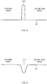
- FIG. 8 is an explanatory diagram illustrating an example of a case where the feeding plate 51 is not used.
- the bottom portion 20 is provided with a convex member 510 that protrudes upward.
- the convex member 510 is provided continuously between the feeding area and the excretion area. Also in the case where the continuous convex member 510 is provided between the feeding area and the excretion area in this manner, it is possible to prevent food from rolling out onto the excretion area. Note that the feeding area is fixed in this case. In contrast, in the case where the feeding plate 51 is used, the feeding area can be moved appropriately.
- FIG. 9 is an explanatory diagram illustrating another example of a case where the feeding plate 51 is not used.
- a groove portion 511 that is concave downward is formed in the bottom portion 20.
- the groove portion 511 is provided continuously between the feeding area and the excretion area. Also in the case where the continuous groove portion 511 is provided between the feeding area and the excretion area in this manner, it is possible to prevent food from rolling out onto the excretion area. Note also that in this case, the feeding area is fixed.
- the feeder 52 is arranged outside the wall portion 30.
- the arrangement is not limited to this and the feeder 52 may be arranged within the wall portion 30.
- the feeder 52 is arranged outside the wall portion 30, it is possible to widen an area in the toilet (excretion area). In addition, it is possible to prevent the dog from eating food stored in the feeder 52 (specifically, the food container 100).
- the feeder 52 is not limited to the one described above, and may have any size and any configuration.
- the access opening 33 is formed by making an opening at a portion of the wall portion 30.
- the configuration is not limited to this.
- a slidable door may be provided.
- an automatic door that allows a dog to enter and exit by itself is desirable.
- the urination detection sensor 40 is a sensor that detects whether there is urination on the basis of whether there is conduction of electricity between the positive electrode 41 and the negative electrode 42.
- the urination detection sensor 40 is not limited to this and may be a sensor of another type.
- a light-emitting unit and a light-receiving unit of an infrared sensor may be provided respectively on one side and the other side of the urination area in the left-right direction (or the front-rear direction). It is also possible to determine whether there is urination in this case depending on whether infrared radiation is blocked by urine.
Landscapes
- Life Sciences & Earth Sciences (AREA)
- Environmental Sciences (AREA)
- Animal Husbandry (AREA)
- Biodiversity & Conservation Biology (AREA)
- Zoology (AREA)
- Biophysics (AREA)
- Birds (AREA)
- Housing For Livestock And Birds (AREA)
- Orthopedics, Nursing, And Contraception (AREA)
- Feeding And Watering For Cattle Raising And Animal Husbandry (AREA)
Applications Claiming Priority (2)
| Application Number | Priority Date | Filing Date | Title |
|---|---|---|---|
| JP2017245892A JP7060954B2 (ja) | 2017-12-22 | 2017-12-22 | 犬用トイレ |
| PCT/JP2018/043013 WO2019123959A1 (ja) | 2017-12-22 | 2018-11-21 | 犬用トイレ |
Publications (3)
| Publication Number | Publication Date |
|---|---|
| EP3682736A1 true EP3682736A1 (de) | 2020-07-22 |
| EP3682736A4 EP3682736A4 (de) | 2020-12-02 |
| EP3682736B1 EP3682736B1 (de) | 2024-01-24 |
Family
ID=66993298
Family Applications (1)
| Application Number | Title | Priority Date | Filing Date |
|---|---|---|---|
| EP18892937.6A Active EP3682736B1 (de) | 2017-12-22 | 2018-11-21 | Hundetoilette |
Country Status (5)
| Country | Link |
|---|---|
| US (1) | US20200245586A1 (de) |
| EP (1) | EP3682736B1 (de) |
| JP (1) | JP7060954B2 (de) |
| CN (1) | CN111479461B (de) |
| WO (1) | WO2019123959A1 (de) |
Families Citing this family (3)
| Publication number | Priority date | Publication date | Assignee | Title |
|---|---|---|---|---|
| KR102572042B1 (ko) * | 2020-08-28 | 2023-08-29 | 김태현 | 애완동물의 수세식 변기의 배변훈련장치 |
| CN112243868A (zh) * | 2020-10-22 | 2021-01-22 | 珠海格力电器股份有限公司 | 一种设备控制方法、装置、电子设备及可读存储介质 |
| US12543697B2 (en) * | 2023-11-16 | 2026-02-10 | Dana Leslie | Animal waste station |
Family Cites Families (10)
| Publication number | Priority date | Publication date | Assignee | Title |
|---|---|---|---|---|
| US6983719B2 (en) * | 2000-08-30 | 2006-01-10 | Gavin Armstrong | Animal behavior training apparatus |
| JP2006238780A (ja) * | 2005-03-03 | 2006-09-14 | Ooshima Design Sekkei:Kk | ペット用トイレ |
| CN100413405C (zh) * | 2005-03-22 | 2008-08-27 | 许正琳 | 排便训练用宠物排泄物处理装置 |
| JP4945260B2 (ja) * | 2007-02-14 | 2012-06-06 | 株式会社ボンビ | ペット用ケージ |
| JP2009045053A (ja) | 2007-08-20 | 2009-03-05 | Inteimetto Kk | ペットのトイレトレーニング装置 |
| AU2013299897A1 (en) * | 2012-08-06 | 2015-02-26 | Radio Systems Corporation | Housebreaking reward system |
| US9737045B1 (en) * | 2014-03-17 | 2017-08-22 | Equipt4 LLC | Pet waste station and training device |
| CN105309319B (zh) * | 2014-06-04 | 2018-11-06 | 姜伟 | 宠物自动如厕系统及方法 |
| KR20160065568A (ko) * | 2014-12-01 | 2016-06-09 | 김재원 | 애완견용 배설 학습기구 |
| JP3204296U (ja) * | 2016-03-08 | 2016-05-26 | アイリスオーヤマ株式会社 | ペット用サークル |
-
2017
- 2017-12-22 JP JP2017245892A patent/JP7060954B2/ja active Active
-
2018
- 2018-11-21 CN CN201880074959.6A patent/CN111479461B/zh active Active
- 2018-11-21 WO PCT/JP2018/043013 patent/WO2019123959A1/ja not_active Ceased
- 2018-11-21 EP EP18892937.6A patent/EP3682736B1/de active Active
-
2020
- 2020-04-20 US US16/852,818 patent/US20200245586A1/en not_active Abandoned
Also Published As
| Publication number | Publication date |
|---|---|
| JP2019110795A (ja) | 2019-07-11 |
| EP3682736B1 (de) | 2024-01-24 |
| CN111479461B (zh) | 2022-10-11 |
| EP3682736A4 (de) | 2020-12-02 |
| JP7060954B2 (ja) | 2022-04-27 |
| WO2019123959A1 (ja) | 2019-06-27 |
| CN111479461A (zh) | 2020-07-31 |
| US20200245586A1 (en) | 2020-08-06 |
Similar Documents
| Publication | Publication Date | Title |
|---|---|---|
| US20200245586A1 (en) | Dog toilet | |
| US11523585B2 (en) | Dog toilet | |
| US9737045B1 (en) | Pet waste station and training device | |
| JP6353826B2 (ja) | 動物用トイレ | |
| JP7279124B2 (ja) | 猫の体調管理を行うシステム、及び床プレート | |
| JP2020130031A (ja) | 動物用トイレ | |
| EP1274298A1 (de) | Kleiner streubehälter für tiere | |
| CN112955005A (zh) | 动物用厕所 | |
| CN112752503A (zh) | 动物用厕所 | |
| JP6356934B1 (ja) | 動物用トイレ | |
| KR101410088B1 (ko) | 식수 및 사료 급이기의 위생 사료받침대 | |
| JP7675003B2 (ja) | ペット用採尿容器及びペット用トイレ | |
| JP6421269B1 (ja) | 動物用トイレ及びシステム | |
| JP6421275B1 (ja) | 動物用トイレ | |
| JP2957219B2 (ja) | 乳用家畜を清潔に飼育する装置 | |
| JP6719032B1 (ja) | 動物用トイレ | |
| JP6421270B1 (ja) | 動物用トイレ及びシステム | |
| KR20240063500A (ko) | 반려동물용 스마트 배변판 | |
| JP2018186824A (ja) | 動物用トイレ及びシステム | |
| KR20210004682A (ko) | 반려동물 배설물 처리 장치 | |
| JP2019022487A (ja) | 動物用トイレ | |
| WO2015178802A1 (ru) | Туалет для кошек с вертикальным входом |
Legal Events
| Date | Code | Title | Description |
|---|---|---|---|
| STAA | Information on the status of an ep patent application or granted ep patent |
Free format text: STATUS: THE INTERNATIONAL PUBLICATION HAS BEEN MADE |
|
| PUAI | Public reference made under article 153(3) epc to a published international application that has entered the european phase |
Free format text: ORIGINAL CODE: 0009012 |
|
| STAA | Information on the status of an ep patent application or granted ep patent |
Free format text: STATUS: REQUEST FOR EXAMINATION WAS MADE |
|
| 17P | Request for examination filed |
Effective date: 20200415 |
|
| AK | Designated contracting states |
Kind code of ref document: A1 Designated state(s): AL AT BE BG CH CY CZ DE DK EE ES FI FR GB GR HR HU IE IS IT LI LT LU LV MC MK MT NL NO PL PT RO RS SE SI SK SM TR |
|
| AX | Request for extension of the european patent |
Extension state: BA ME |
|
| A4 | Supplementary search report drawn up and despatched |
Effective date: 20201030 |
|
| RIC1 | Information provided on ipc code assigned before grant |
Ipc: A01K 5/02 20060101ALI20201026BHEP Ipc: A01K 23/00 20060101AFI20201026BHEP Ipc: A01K 1/015 20060101ALI20201026BHEP Ipc: A01K 15/02 20060101ALI20201026BHEP |
|
| DAV | Request for validation of the european patent (deleted) | ||
| DAX | Request for extension of the european patent (deleted) | ||
| RIN1 | Information on inventor provided before grant (corrected) |
Inventor name: HIROSHIMA, KENJI Inventor name: MATSUO, TAKAYUKI |
|
| GRAP | Despatch of communication of intention to grant a patent |
Free format text: ORIGINAL CODE: EPIDOSNIGR1 |
|
| STAA | Information on the status of an ep patent application or granted ep patent |
Free format text: STATUS: GRANT OF PATENT IS INTENDED |
|
| INTG | Intention to grant announced |
Effective date: 20231017 |
|
| GRAS | Grant fee paid |
Free format text: ORIGINAL CODE: EPIDOSNIGR3 |
|
| GRAA | (expected) grant |
Free format text: ORIGINAL CODE: 0009210 |
|
| STAA | Information on the status of an ep patent application or granted ep patent |
Free format text: STATUS: THE PATENT HAS BEEN GRANTED |
|
| AK | Designated contracting states |
Kind code of ref document: B1 Designated state(s): AL AT BE BG CH CY CZ DE DK EE ES FI FR GB GR HR HU IE IS IT LI LT LU LV MC MK MT NL NO PL PT RO RS SE SI SK SM TR |
|
| REG | Reference to a national code |
Ref country code: GB Ref legal event code: FG4D |
|
| REG | Reference to a national code |
Ref country code: CH Ref legal event code: EP |
|
| REG | Reference to a national code |
Ref country code: IE Ref legal event code: FG4D |
|
| REG | Reference to a national code |
Ref country code: DE Ref legal event code: R096 Ref document number: 602018064657 Country of ref document: DE |
|
| REG | Reference to a national code |
Ref country code: LT Ref legal event code: MG9D |
|
| REG | Reference to a national code |
Ref country code: NL Ref legal event code: MP Effective date: 20240124 |
|
| PG25 | Lapsed in a contracting state [announced via postgrant information from national office to epo] |
Ref country code: NL Free format text: LAPSE BECAUSE OF FAILURE TO SUBMIT A TRANSLATION OF THE DESCRIPTION OR TO PAY THE FEE WITHIN THE PRESCRIBED TIME-LIMIT Effective date: 20240124 |
|
| PG25 | Lapsed in a contracting state [announced via postgrant information from national office to epo] |
Ref country code: NL Free format text: LAPSE BECAUSE OF FAILURE TO SUBMIT A TRANSLATION OF THE DESCRIPTION OR TO PAY THE FEE WITHIN THE PRESCRIBED TIME-LIMIT Effective date: 20240124 |
|
| PG25 | Lapsed in a contracting state [announced via postgrant information from national office to epo] |
Ref country code: IS Free format text: LAPSE BECAUSE OF FAILURE TO SUBMIT A TRANSLATION OF THE DESCRIPTION OR TO PAY THE FEE WITHIN THE PRESCRIBED TIME-LIMIT Effective date: 20240524 |
|
| PG25 | Lapsed in a contracting state [announced via postgrant information from national office to epo] |
Ref country code: LT Free format text: LAPSE BECAUSE OF FAILURE TO SUBMIT A TRANSLATION OF THE DESCRIPTION OR TO PAY THE FEE WITHIN THE PRESCRIBED TIME-LIMIT Effective date: 20240124 |
|
| PG25 | Lapsed in a contracting state [announced via postgrant information from national office to epo] |
Ref country code: GR Free format text: LAPSE BECAUSE OF FAILURE TO SUBMIT A TRANSLATION OF THE DESCRIPTION OR TO PAY THE FEE WITHIN THE PRESCRIBED TIME-LIMIT Effective date: 20240425 |
|
| REG | Reference to a national code |
Ref country code: AT Ref legal event code: MK05 Ref document number: 1651406 Country of ref document: AT Kind code of ref document: T Effective date: 20240124 |
|
| PG25 | Lapsed in a contracting state [announced via postgrant information from national office to epo] |
Ref country code: RS Free format text: LAPSE BECAUSE OF FAILURE TO SUBMIT A TRANSLATION OF THE DESCRIPTION OR TO PAY THE FEE WITHIN THE PRESCRIBED TIME-LIMIT Effective date: 20240424 Ref country code: HR Free format text: LAPSE BECAUSE OF FAILURE TO SUBMIT A TRANSLATION OF THE DESCRIPTION OR TO PAY THE FEE WITHIN THE PRESCRIBED TIME-LIMIT Effective date: 20240124 |
|
| PG25 | Lapsed in a contracting state [announced via postgrant information from national office to epo] |
Ref country code: ES Free format text: LAPSE BECAUSE OF FAILURE TO SUBMIT A TRANSLATION OF THE DESCRIPTION OR TO PAY THE FEE WITHIN THE PRESCRIBED TIME-LIMIT Effective date: 20240124 |
|
| PG25 | Lapsed in a contracting state [announced via postgrant information from national office to epo] |
Ref country code: AT Free format text: LAPSE BECAUSE OF FAILURE TO SUBMIT A TRANSLATION OF THE DESCRIPTION OR TO PAY THE FEE WITHIN THE PRESCRIBED TIME-LIMIT Effective date: 20240124 |
|
| PG25 | Lapsed in a contracting state [announced via postgrant information from national office to epo] |
Ref country code: RS Free format text: LAPSE BECAUSE OF FAILURE TO SUBMIT A TRANSLATION OF THE DESCRIPTION OR TO PAY THE FEE WITHIN THE PRESCRIBED TIME-LIMIT Effective date: 20240424 Ref country code: NO Free format text: LAPSE BECAUSE OF FAILURE TO SUBMIT A TRANSLATION OF THE DESCRIPTION OR TO PAY THE FEE WITHIN THE PRESCRIBED TIME-LIMIT Effective date: 20240424 Ref country code: LT Free format text: LAPSE BECAUSE OF FAILURE TO SUBMIT A TRANSLATION OF THE DESCRIPTION OR TO PAY THE FEE WITHIN THE PRESCRIBED TIME-LIMIT Effective date: 20240124 Ref country code: IS Free format text: LAPSE BECAUSE OF FAILURE TO SUBMIT A TRANSLATION OF THE DESCRIPTION OR TO PAY THE FEE WITHIN THE PRESCRIBED TIME-LIMIT Effective date: 20240524 Ref country code: HR Free format text: LAPSE BECAUSE OF FAILURE TO SUBMIT A TRANSLATION OF THE DESCRIPTION OR TO PAY THE FEE WITHIN THE PRESCRIBED TIME-LIMIT Effective date: 20240124 Ref country code: GR Free format text: LAPSE BECAUSE OF FAILURE TO SUBMIT A TRANSLATION OF THE DESCRIPTION OR TO PAY THE FEE WITHIN THE PRESCRIBED TIME-LIMIT Effective date: 20240425 Ref country code: FI Free format text: LAPSE BECAUSE OF FAILURE TO SUBMIT A TRANSLATION OF THE DESCRIPTION OR TO PAY THE FEE WITHIN THE PRESCRIBED TIME-LIMIT Effective date: 20240124 Ref country code: ES Free format text: LAPSE BECAUSE OF FAILURE TO SUBMIT A TRANSLATION OF THE DESCRIPTION OR TO PAY THE FEE WITHIN THE PRESCRIBED TIME-LIMIT Effective date: 20240124 Ref country code: BG Free format text: LAPSE BECAUSE OF FAILURE TO SUBMIT A TRANSLATION OF THE DESCRIPTION OR TO PAY THE FEE WITHIN THE PRESCRIBED TIME-LIMIT Effective date: 20240124 Ref country code: AT Free format text: LAPSE BECAUSE OF FAILURE TO SUBMIT A TRANSLATION OF THE DESCRIPTION OR TO PAY THE FEE WITHIN THE PRESCRIBED TIME-LIMIT Effective date: 20240124 |
|
| PG25 | Lapsed in a contracting state [announced via postgrant information from national office to epo] |
Ref country code: PL Free format text: LAPSE BECAUSE OF FAILURE TO SUBMIT A TRANSLATION OF THE DESCRIPTION OR TO PAY THE FEE WITHIN THE PRESCRIBED TIME-LIMIT Effective date: 20240124 Ref country code: PT Free format text: LAPSE BECAUSE OF FAILURE TO SUBMIT A TRANSLATION OF THE DESCRIPTION OR TO PAY THE FEE WITHIN THE PRESCRIBED TIME-LIMIT Effective date: 20240524 |
|
| PG25 | Lapsed in a contracting state [announced via postgrant information from national office to epo] |
Ref country code: SE Free format text: LAPSE BECAUSE OF FAILURE TO SUBMIT A TRANSLATION OF THE DESCRIPTION OR TO PAY THE FEE WITHIN THE PRESCRIBED TIME-LIMIT Effective date: 20240124 Ref country code: PT Free format text: LAPSE BECAUSE OF FAILURE TO SUBMIT A TRANSLATION OF THE DESCRIPTION OR TO PAY THE FEE WITHIN THE PRESCRIBED TIME-LIMIT Effective date: 20240524 Ref country code: PL Free format text: LAPSE BECAUSE OF FAILURE TO SUBMIT A TRANSLATION OF THE DESCRIPTION OR TO PAY THE FEE WITHIN THE PRESCRIBED TIME-LIMIT Effective date: 20240124 Ref country code: LV Free format text: LAPSE BECAUSE OF FAILURE TO SUBMIT A TRANSLATION OF THE DESCRIPTION OR TO PAY THE FEE WITHIN THE PRESCRIBED TIME-LIMIT Effective date: 20240124 |
|
| PG25 | Lapsed in a contracting state [announced via postgrant information from national office to epo] |
Ref country code: DK Free format text: LAPSE BECAUSE OF FAILURE TO SUBMIT A TRANSLATION OF THE DESCRIPTION OR TO PAY THE FEE WITHIN THE PRESCRIBED TIME-LIMIT Effective date: 20240124 |
|
| PG25 | Lapsed in a contracting state [announced via postgrant information from national office to epo] |
Ref country code: SM Free format text: LAPSE BECAUSE OF FAILURE TO SUBMIT A TRANSLATION OF THE DESCRIPTION OR TO PAY THE FEE WITHIN THE PRESCRIBED TIME-LIMIT Effective date: 20240124 |
|
| PG25 | Lapsed in a contracting state [announced via postgrant information from national office to epo] |
Ref country code: EE Free format text: LAPSE BECAUSE OF FAILURE TO SUBMIT A TRANSLATION OF THE DESCRIPTION OR TO PAY THE FEE WITHIN THE PRESCRIBED TIME-LIMIT Effective date: 20240124 Ref country code: CZ Free format text: LAPSE BECAUSE OF FAILURE TO SUBMIT A TRANSLATION OF THE DESCRIPTION OR TO PAY THE FEE WITHIN THE PRESCRIBED TIME-LIMIT Effective date: 20240124 |
|
| REG | Reference to a national code |
Ref country code: DE Ref legal event code: R097 Ref document number: 602018064657 Country of ref document: DE |
|
| PG25 | Lapsed in a contracting state [announced via postgrant information from national office to epo] |
Ref country code: SK Free format text: LAPSE BECAUSE OF FAILURE TO SUBMIT A TRANSLATION OF THE DESCRIPTION OR TO PAY THE FEE WITHIN THE PRESCRIBED TIME-LIMIT Effective date: 20240124 |
|
| PG25 | Lapsed in a contracting state [announced via postgrant information from national office to epo] |
Ref country code: SM Free format text: LAPSE BECAUSE OF FAILURE TO SUBMIT A TRANSLATION OF THE DESCRIPTION OR TO PAY THE FEE WITHIN THE PRESCRIBED TIME-LIMIT Effective date: 20240124 Ref country code: SK Free format text: LAPSE BECAUSE OF FAILURE TO SUBMIT A TRANSLATION OF THE DESCRIPTION OR TO PAY THE FEE WITHIN THE PRESCRIBED TIME-LIMIT Effective date: 20240124 Ref country code: RO Free format text: LAPSE BECAUSE OF FAILURE TO SUBMIT A TRANSLATION OF THE DESCRIPTION OR TO PAY THE FEE WITHIN THE PRESCRIBED TIME-LIMIT Effective date: 20240124 Ref country code: EE Free format text: LAPSE BECAUSE OF FAILURE TO SUBMIT A TRANSLATION OF THE DESCRIPTION OR TO PAY THE FEE WITHIN THE PRESCRIBED TIME-LIMIT Effective date: 20240124 Ref country code: DK Free format text: LAPSE BECAUSE OF FAILURE TO SUBMIT A TRANSLATION OF THE DESCRIPTION OR TO PAY THE FEE WITHIN THE PRESCRIBED TIME-LIMIT Effective date: 20240124 Ref country code: CZ Free format text: LAPSE BECAUSE OF FAILURE TO SUBMIT A TRANSLATION OF THE DESCRIPTION OR TO PAY THE FEE WITHIN THE PRESCRIBED TIME-LIMIT Effective date: 20240124 |
|
| PLBE | No opposition filed within time limit |
Free format text: ORIGINAL CODE: 0009261 |
|
| STAA | Information on the status of an ep patent application or granted ep patent |
Free format text: STATUS: NO OPPOSITION FILED WITHIN TIME LIMIT |
|
| PG25 | Lapsed in a contracting state [announced via postgrant information from national office to epo] |
Ref country code: IT Free format text: LAPSE BECAUSE OF FAILURE TO SUBMIT A TRANSLATION OF THE DESCRIPTION OR TO PAY THE FEE WITHIN THE PRESCRIBED TIME-LIMIT Effective date: 20240124 |
|
| PG25 | Lapsed in a contracting state [announced via postgrant information from national office to epo] |
Ref country code: IT Free format text: LAPSE BECAUSE OF FAILURE TO SUBMIT A TRANSLATION OF THE DESCRIPTION OR TO PAY THE FEE WITHIN THE PRESCRIBED TIME-LIMIT Effective date: 20240124 |
|
| 26N | No opposition filed |
Effective date: 20241025 |
|
| PG25 | Lapsed in a contracting state [announced via postgrant information from national office to epo] |
Ref country code: SI Free format text: LAPSE BECAUSE OF FAILURE TO SUBMIT A TRANSLATION OF THE DESCRIPTION OR TO PAY THE FEE WITHIN THE PRESCRIBED TIME-LIMIT Effective date: 20240124 |
|
| REG | Reference to a national code |
Ref country code: DE Ref legal event code: R119 Ref document number: 602018064657 Country of ref document: DE |
|
| REG | Reference to a national code |
Ref country code: CH Ref legal event code: PL |
|
| PG25 | Lapsed in a contracting state [announced via postgrant information from national office to epo] |
Ref country code: MC Free format text: LAPSE BECAUSE OF FAILURE TO SUBMIT A TRANSLATION OF THE DESCRIPTION OR TO PAY THE FEE WITHIN THE PRESCRIBED TIME-LIMIT Effective date: 20240124 |
|
| PG25 | Lapsed in a contracting state [announced via postgrant information from national office to epo] |
Ref country code: LU Free format text: LAPSE BECAUSE OF NON-PAYMENT OF DUE FEES Effective date: 20241121 |
|
| REG | Reference to a national code |
Ref country code: CH Ref legal event code: PL |
|
| GBPC | Gb: european patent ceased through non-payment of renewal fee |
Effective date: 20241121 |
|
| PG25 | Lapsed in a contracting state [announced via postgrant information from national office to epo] |
Ref country code: CH Free format text: LAPSE BECAUSE OF NON-PAYMENT OF DUE FEES Effective date: 20241130 |
|
| REG | Reference to a national code |
Ref country code: BE Ref legal event code: MM Effective date: 20241130 |
|
| PG25 | Lapsed in a contracting state [announced via postgrant information from national office to epo] |
Ref country code: DE Free format text: LAPSE BECAUSE OF NON-PAYMENT OF DUE FEES Effective date: 20250603 |
|
| PG25 | Lapsed in a contracting state [announced via postgrant information from national office to epo] |
Ref country code: GB Free format text: LAPSE BECAUSE OF NON-PAYMENT OF DUE FEES Effective date: 20241121 Ref country code: BE Free format text: LAPSE BECAUSE OF NON-PAYMENT OF DUE FEES Effective date: 20241130 |
|
| PG25 | Lapsed in a contracting state [announced via postgrant information from national office to epo] |
Ref country code: FR Free format text: LAPSE BECAUSE OF NON-PAYMENT OF DUE FEES Effective date: 20241130 |
|
| PG25 | Lapsed in a contracting state [announced via postgrant information from national office to epo] |
Ref country code: IE Free format text: LAPSE BECAUSE OF NON-PAYMENT OF DUE FEES Effective date: 20241121 |
|
| PG25 | Lapsed in a contracting state [announced via postgrant information from national office to epo] |
Ref country code: HU Free format text: LAPSE BECAUSE OF FAILURE TO SUBMIT A TRANSLATION OF THE DESCRIPTION OR TO PAY THE FEE WITHIN THE PRESCRIBED TIME-LIMIT; INVALID AB INITIO Effective date: 20181121 |
|
| PG25 | Lapsed in a contracting state [announced via postgrant information from national office to epo] |
Ref country code: CY Free format text: LAPSE BECAUSE OF FAILURE TO SUBMIT A TRANSLATION OF THE DESCRIPTION OR TO PAY THE FEE WITHIN THE PRESCRIBED TIME-LIMIT; INVALID AB INITIO Effective date: 20181121 |