EP3683017B1 - Revêtement abrasif pour systèmes mécaniques à haute température et systèmes mécaniques à haute température avec un revêtement abrasif - Google Patents
Revêtement abrasif pour systèmes mécaniques à haute température et systèmes mécaniques à haute température avec un revêtement abrasif Download PDFInfo
- Publication number
- EP3683017B1 EP3683017B1 EP19215750.1A EP19215750A EP3683017B1 EP 3683017 B1 EP3683017 B1 EP 3683017B1 EP 19215750 A EP19215750 A EP 19215750A EP 3683017 B1 EP3683017 B1 EP 3683017B1
- Authority
- EP
- European Patent Office
- Prior art keywords
- abrasive
- coating
- abrasive coating
- blade
- particles
- Prior art date
- Legal status (The legal status is an assumption and is not a legal conclusion. Google has not performed a legal analysis and makes no representation as to the accuracy of the status listed.)
- Active
Links
Images


Classifications
-
- F—MECHANICAL ENGINEERING; LIGHTING; HEATING; WEAPONS; BLASTING
- F01—MACHINES OR ENGINES IN GENERAL; ENGINE PLANTS IN GENERAL; STEAM ENGINES
- F01D—NON-POSITIVE DISPLACEMENT MACHINES OR ENGINES, e.g. STEAM TURBINES
- F01D5/00—Blades; Blade-carrying members; Heating, heat-insulating, cooling or antivibration means on the blades or the members
- F01D5/12—Blades
- F01D5/28—Selecting particular materials; Particular measures relating thereto; Measures against erosion or corrosion
- F01D5/288—Protective coatings for blades
-
- B—PERFORMING OPERATIONS; TRANSPORTING
- B24—GRINDING; POLISHING
- B24D—TOOLS FOR GRINDING, BUFFING OR SHARPENING
- B24D3/00—Physical features of abrasive bodies, or sheets, e.g. abrasive surfaces of special nature; Abrasive bodies or sheets characterised by their constituents
- B24D3/02—Physical features of abrasive bodies, or sheets, e.g. abrasive surfaces of special nature; Abrasive bodies or sheets characterised by their constituents the constituent being used as bonding agent
- B24D3/04—Physical features of abrasive bodies, or sheets, e.g. abrasive surfaces of special nature; Abrasive bodies or sheets characterised by their constituents the constituent being used as bonding agent and being essentially inorganic
- B24D3/06—Physical features of abrasive bodies, or sheets, e.g. abrasive surfaces of special nature; Abrasive bodies or sheets characterised by their constituents the constituent being used as bonding agent and being essentially inorganic metallic or mixture of metals with ceramic materials, e.g. hard metals, "cermets", cements
-
- B—PERFORMING OPERATIONS; TRANSPORTING
- B24—GRINDING; POLISHING
- B24D—TOOLS FOR GRINDING, BUFFING OR SHARPENING
- B24D18/00—Manufacture of grinding tools or other grinding devices, e.g. wheels, not otherwise provided for
-
- B—PERFORMING OPERATIONS; TRANSPORTING
- B33—ADDITIVE MANUFACTURING TECHNOLOGY
- B33Y—ADDITIVE MANUFACTURING, i.e. MANUFACTURING OF THREE-DIMENSIONAL [3D] OBJECTS BY ADDITIVE DEPOSITION, ADDITIVE AGGLOMERATION OR ADDITIVE LAYERING, e.g. BY 3D PRINTING, STEREOLITHOGRAPHY OR SELECTIVE LASER SINTERING
- B33Y80/00—Products made by additive manufacturing
-
- C—CHEMISTRY; METALLURGY
- C09—DYES; PAINTS; POLISHES; NATURAL RESINS; ADHESIVES; COMPOSITIONS NOT OTHERWISE PROVIDED FOR; APPLICATIONS OF MATERIALS NOT OTHERWISE PROVIDED FOR
- C09K—MATERIALS FOR MISCELLANEOUS APPLICATIONS, NOT PROVIDED FOR ELSEWHERE
- C09K3/00—Materials not provided for elsewhere
- C09K3/14—Anti-slip materials; Abrasives
- C09K3/1409—Abrasive particles per se
-
- C—CHEMISTRY; METALLURGY
- C22—METALLURGY; FERROUS OR NON-FERROUS ALLOYS; TREATMENT OF ALLOYS OR NON-FERROUS METALS
- C22C—ALLOYS
- C22C19/00—Alloys based on nickel or cobalt
- C22C19/03—Alloys based on nickel or cobalt based on nickel
- C22C19/05—Alloys based on nickel or cobalt based on nickel with chromium
-
- F—MECHANICAL ENGINEERING; LIGHTING; HEATING; WEAPONS; BLASTING
- F01—MACHINES OR ENGINES IN GENERAL; ENGINE PLANTS IN GENERAL; STEAM ENGINES
- F01D—NON-POSITIVE DISPLACEMENT MACHINES OR ENGINES, e.g. STEAM TURBINES
- F01D11/00—Preventing or minimising internal leakage of working-fluid, e.g. between stages
- F01D11/08—Preventing or minimising internal leakage of working-fluid, e.g. between stages for sealing space between rotor blade tips and stator
- F01D11/12—Preventing or minimising internal leakage of working-fluid, e.g. between stages for sealing space between rotor blade tips and stator using a rubstrip, e.g. erodible. deformable or resiliently-biased part
- F01D11/122—Preventing or minimising internal leakage of working-fluid, e.g. between stages for sealing space between rotor blade tips and stator using a rubstrip, e.g. erodible. deformable or resiliently-biased part with erodable or abradable material
-
- F—MECHANICAL ENGINEERING; LIGHTING; HEATING; WEAPONS; BLASTING
- F01—MACHINES OR ENGINES IN GENERAL; ENGINE PLANTS IN GENERAL; STEAM ENGINES
- F01D—NON-POSITIVE DISPLACEMENT MACHINES OR ENGINES, e.g. STEAM TURBINES
- F01D5/00—Blades; Blade-carrying members; Heating, heat-insulating, cooling or antivibration means on the blades or the members
- F01D5/12—Blades
- F01D5/28—Selecting particular materials; Particular measures relating thereto; Measures against erosion or corrosion
- F01D5/282—Selecting composite materials, e.g. blades with reinforcing filaments
-
- F—MECHANICAL ENGINEERING; LIGHTING; HEATING; WEAPONS; BLASTING
- F01—MACHINES OR ENGINES IN GENERAL; ENGINE PLANTS IN GENERAL; STEAM ENGINES
- F01D—NON-POSITIVE DISPLACEMENT MACHINES OR ENGINES, e.g. STEAM TURBINES
- F01D5/00—Blades; Blade-carrying members; Heating, heat-insulating, cooling or antivibration means on the blades or the members
- F01D5/12—Blades
- F01D5/28—Selecting particular materials; Particular measures relating thereto; Measures against erosion or corrosion
- F01D5/284—Selection of ceramic materials
-
- F—MECHANICAL ENGINEERING; LIGHTING; HEATING; WEAPONS; BLASTING
- F01—MACHINES OR ENGINES IN GENERAL; ENGINE PLANTS IN GENERAL; STEAM ENGINES
- F01D—NON-POSITIVE DISPLACEMENT MACHINES OR ENGINES, e.g. STEAM TURBINES
- F01D5/00—Blades; Blade-carrying members; Heating, heat-insulating, cooling or antivibration means on the blades or the members
- F01D5/12—Blades
- F01D5/28—Selecting particular materials; Particular measures relating thereto; Measures against erosion or corrosion
- F01D5/286—Particular treatment of blades, e.g. to increase durability or resistance against corrosion or erosion
-
- F—MECHANICAL ENGINEERING; LIGHTING; HEATING; WEAPONS; BLASTING
- F01—MACHINES OR ENGINES IN GENERAL; ENGINE PLANTS IN GENERAL; STEAM ENGINES
- F01D—NON-POSITIVE DISPLACEMENT MACHINES OR ENGINES, e.g. STEAM TURBINES
- F01D11/00—Preventing or minimising internal leakage of working-fluid, e.g. between stages
- F01D11/001—Preventing or minimising internal leakage of working-fluid, e.g. between stages for sealing space between stator blade and rotor
-
- F—MECHANICAL ENGINEERING; LIGHTING; HEATING; WEAPONS; BLASTING
- F05—INDEXING SCHEMES RELATING TO ENGINES OR PUMPS IN VARIOUS SUBCLASSES OF CLASSES F01-F04
- F05D—INDEXING SCHEME FOR ASPECTS RELATING TO NON-POSITIVE-DISPLACEMENT MACHINES OR ENGINES, GAS-TURBINES OR JET-PROPULSION PLANTS
- F05D2230/00—Manufacture
- F05D2230/10—Manufacture by removing material
- F05D2230/11—Manufacture by removing material by electrochemical methods
-
- F—MECHANICAL ENGINEERING; LIGHTING; HEATING; WEAPONS; BLASTING
- F05—INDEXING SCHEMES RELATING TO ENGINES OR PUMPS IN VARIOUS SUBCLASSES OF CLASSES F01-F04
- F05D—INDEXING SCHEME FOR ASPECTS RELATING TO NON-POSITIVE-DISPLACEMENT MACHINES OR ENGINES, GAS-TURBINES OR JET-PROPULSION PLANTS
- F05D2300/00—Materials; Properties thereof
- F05D2300/20—Oxide or non-oxide ceramics
- F05D2300/21—Oxide ceramics
-
- F—MECHANICAL ENGINEERING; LIGHTING; HEATING; WEAPONS; BLASTING
- F05—INDEXING SCHEMES RELATING TO ENGINES OR PUMPS IN VARIOUS SUBCLASSES OF CLASSES F01-F04
- F05D—INDEXING SCHEME FOR ASPECTS RELATING TO NON-POSITIVE-DISPLACEMENT MACHINES OR ENGINES, GAS-TURBINES OR JET-PROPULSION PLANTS
- F05D2300/00—Materials; Properties thereof
- F05D2300/20—Oxide or non-oxide ceramics
- F05D2300/22—Non-oxide ceramics
- F05D2300/226—Carbides
- F05D2300/2261—Carbides of silicon
-
- F—MECHANICAL ENGINEERING; LIGHTING; HEATING; WEAPONS; BLASTING
- F05—INDEXING SCHEMES RELATING TO ENGINES OR PUMPS IN VARIOUS SUBCLASSES OF CLASSES F01-F04
- F05D—INDEXING SCHEME FOR ASPECTS RELATING TO NON-POSITIVE-DISPLACEMENT MACHINES OR ENGINES, GAS-TURBINES OR JET-PROPULSION PLANTS
- F05D2300/00—Materials; Properties thereof
- F05D2300/20—Oxide or non-oxide ceramics
- F05D2300/22—Non-oxide ceramics
- F05D2300/228—Nitrides
- F05D2300/2282—Nitrides of boron
-
- F—MECHANICAL ENGINEERING; LIGHTING; HEATING; WEAPONS; BLASTING
- F05—INDEXING SCHEMES RELATING TO ENGINES OR PUMPS IN VARIOUS SUBCLASSES OF CLASSES F01-F04
- F05D—INDEXING SCHEME FOR ASPECTS RELATING TO NON-POSITIVE-DISPLACEMENT MACHINES OR ENGINES, GAS-TURBINES OR JET-PROPULSION PLANTS
- F05D2300/00—Materials; Properties thereof
- F05D2300/20—Oxide or non-oxide ceramics
- F05D2300/22—Non-oxide ceramics
- F05D2300/228—Nitrides
- F05D2300/2283—Nitrides of silicon
-
- F—MECHANICAL ENGINEERING; LIGHTING; HEATING; WEAPONS; BLASTING
- F05—INDEXING SCHEMES RELATING TO ENGINES OR PUMPS IN VARIOUS SUBCLASSES OF CLASSES F01-F04
- F05D—INDEXING SCHEME FOR ASPECTS RELATING TO NON-POSITIVE-DISPLACEMENT MACHINES OR ENGINES, GAS-TURBINES OR JET-PROPULSION PLANTS
- F05D2300/00—Materials; Properties thereof
- F05D2300/60—Properties or characteristics given to material by treatment or manufacturing
- F05D2300/603—Composites; e.g. fibre-reinforced
- F05D2300/6033—Ceramic matrix composites [CMC]
-
- Y—GENERAL TAGGING OF NEW TECHNOLOGICAL DEVELOPMENTS; GENERAL TAGGING OF CROSS-SECTIONAL TECHNOLOGIES SPANNING OVER SEVERAL SECTIONS OF THE IPC; TECHNICAL SUBJECTS COVERED BY FORMER USPC CROSS-REFERENCE ART COLLECTIONS [XRACs] AND DIGESTS
- Y02—TECHNOLOGIES OR APPLICATIONS FOR MITIGATION OR ADAPTATION AGAINST CLIMATE CHANGE
- Y02T—CLIMATE CHANGE MITIGATION TECHNOLOGIES RELATED TO TRANSPORTATION
- Y02T50/00—Aeronautics or air transport
- Y02T50/60—Efficient propulsion technologies, e.g. for aircraft
Definitions
- the present disclosure generally relates to coating systems for high-temperature mechanical systems, such as gas turbine engines.
- components of gas turbine engines operate in severe environments.
- the high-pressure turbine airfoils exposed to hot gases in commercial aeronautical engines typically experience surface temperatures of about 1000°C.
- Components of high-temperature mechanical systems may include a superalloy substrate, a ceramic substrate, or a ceramic matrix composite (CMC) substrate.
- the substrates may be coated with one or more coatings to modify properties of the surface of the substrate.
- superalloy, ceramic, or CMC substrates may be coated with a thermal barrier coating to reduce heat transfer from the external environment to the substrate, an environmental barrier coating to reduce exposure of the substrate to environmental species, such as oxygen, water vapor, or Calcia-Magnesia-Alumina Silicate (CMAS) containing materials, an abradable coating to improve a seal between the substrate and an adjacent component, or combinations thereof.
- a thermal barrier coating to reduce heat transfer from the external environment to the substrate
- an environmental barrier coating to reduce exposure of the substrate to environmental species, such as oxygen, water vapor, or Calcia-Magnesia-Alumina Silicate (CMAS) containing materials
- CMAS Calcia-Magnesia-Alumina Silicate
- the disclosure is directed to techniques for forming abrasive coatings on substrates, such as, a substrate of a component used in high-temperature gas turbine engine.
- the abrasive coating may be formed on turbine blades, turbine vanes, and/or knife rings such that the abrasive coating abrades an abradable coating on an opposing component during operation of the turbine engine.
- the abradable and abrasive coatings may be parts of a system that forms a fluid seal between the opposing components through the abrasion of the abradable layer during operation of the engine, e.g., to improve the efficiency of the engine.
- the abrasive coating may be machined and etched following the initial formation of the abrasive coating on a substrate.
- the machining and etching may provide for an abrasive coating having a desired layer thickness profile with abrasive particles protruding from the metal matrix of the abrasive coating.
- United States Patent No. US 4,741,973 A which is the basis for the preamble of appended claim 1, discloses a means for fabricating an abrasive layer on a blade in a turbine engine, the abrasive layer comprising coated ceramic particles and a matrix material which is treated such that the ceramic particles protrude over the matrix material surface.
- WO 2016/061585 A1 discloses a chemical mechanical polishing pad used for creating a smooth finish to a polished surface.
- the polishing pads include first and second polishing elements, each comprising a plurality of polymer layers.
- EP 3,213,854 A1 discloses a method for repairing components of gas turbine engines, the method comprising forming a molten pool on the component, and depositing material into the molten pool to form a raised track, and controlling the rate at which the molten pool cools so as to control the resulting microstructure of the deposited material.
- the disclosure is directed to a method including forming an abrasive coating system on a substrate, the abrasive coating system including an abrasive coating including a plurality of abrasive particles in a metal matrix, wherein forming the abrasive coating system on the substrate comprises depositing the plurality of abrasive particles and the metal matrix on the substrate using directed energy deposition; machining the abrasive coating on the substrate to define a machined abrasive coating having an abrasive coating thickness profile; and etching an outer surface of the machined abrasive coating to remove a portion of the metal matrix and form an etched metal matrix such that the abrasive particles protrude from the metal matrix; wherein the substrate comprises a blade of a gas turbine engine, the abrasive coating is formed on a blade tip of the blade, and the abrasive coating system of the blade tip is configured to abrade an abradable layer of a blade track during operation of the gas turbine
- the machining may allow for tighter clearances on sealing surfaces, a reduction in leakage, and/or an increase in engine power and/or efficiency. Additionally, etching of the abrasive coating may expose the particles of the abrasive coating on an abrasive grit and may allow the particles to protrude from the metal matrix. As such, the cutting/abrasive surface of the coating may have increased cutting/abrasion effectiveness and reduce rub between the metal matrix of the abrasive coating and the adjacent component.
- the abrasive particles protrude 1 micron to 760 microns from the etched metal matrix.
- the etched metal matrix defines a thickness of 20 microns to 760 microns.
- the abrasive coating defines a thickness of 44 microns to 1000 microns prior to machining.
- the abrasive particles include at least one of cubic boron nitride particles, metal carbide particles, metal nitride particles, and metal oxide particles.
- the metal matrix includes at least one of nickel, titanium, magnesium, cobalt, aluminum, chromium, or alloys thereof.
- etching the outer surface of the machined abrasive coating includes at least one of electrolytically etching the outer surface of the machined abrasive coating and etching via immersion of the outer surface of the coating into an acid.
- the abrasive coating thickness profile of the machined abrasive coating is defined such that a substantially continuous seal is formed between the blade and the blade track during the operation after the abrasive coating has abraded the abradable layer of the blade track during the operation.
- the substrate includes superalloy substrate.
- the abrasive coating includes a plurality of abrasive layers.
- Each abrasive layer includes the plurality of abrasive particles in the metal matrix.
- Forming the abrasive coating system on the substrate includes sequentially forming the plurality of abrasive layers on the substrate.
- a turbine in a gas turbine engine may be formed from a plurality of blade stages coupled to discs that are capable of rotating about an axis.
- Each stage may be formed from at least one rotor and at least one stator.
- Each rotor may include a plurality of turbine blades spaced circumferentially around a respective disc or an integral disc and blades referred to as a blisk.
- Each stage may also include at least one set of non-rotating stators upstream of the rotors.
- the turbine blades may have tips that are located in close proximity to a shroud in a casing that encloses the turbine.
- a large gap between the blade tip and the shroud may decrease the efficiency of the turbine through over-tip leakage.
- a narrow gap increases the risk of "tip rub” where the tip comes into contact with the shroud and causes excessive wear on the components, resulting in damage or even failure of the blade, shroud, or both.
- the tips of the blades may be coated with abrasive particles such as cubic boron nitride (CBN).
- CBN cubic boron nitride
- the particles in the coating may allow the blade tip to abrade or otherwise cut into an abradable coating on the blade shroud during the first use of the blade and establish a tip gap. It is desirable for the particles to remain attached to the turbine tip throughout the life of the tip so that the particles can later cut the seal to compensate for blade changes caused, e.g., by creep during the life of the blade.
- the abrasive coating on the tips of the blade may be deposited using an electroplating process.
- the abrasive coating may be used as deposited or may undergo post deposition machining.
- the electroplating deposition process may form an abrasive coating that has poor adhesion, is susceptible to bubbling, and/or results in the coating being formed on undesired portions of the blade substrates other than the blade tips.
- an abrasive coating including abrasive particles in a metal matrix may be initially formed on a substrate such as on the blade tip of a turbine blade.
- the abrasive coating is formed on the blade tip via directed energy deposition.
- the abrasive coating may then be machined such that the abrasive coating defines a desired layer thickness profile.
- the abrasive coating may also be surface etched to remove a portion of the metal matrix so that the abrasive particles are exposed and protrude from the metal matrix.
- such post processing following formation of the abrasive coating may allow for directed energy deposition or other type of deposition of the abrasive coating, e.g., since the abrasive coatings, as deposited, may have undesirable variations in layer thickness.
- the machining of such abrasive coatings following the initial deposition allows for machining to more exact or precise dimensions, either at a component level or an assembly level. The machining may allow for tighter clearances on the sealing surfaces, a reduction in leakage, and/or an increase in engine power and/or efficiency.
- the selective etching of the abrasive coating exposes the particles of the coating on the abrasive grit and allows the particles to protrude from the metal matrix.
- the cutting/abrasive surface of the coating may have increased cutting/abrasion effectiveness and reduce rub between the metal matrix of the abrasive coating and the adjacent component.
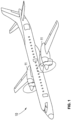
- aircraft 10 including two gas turbine engines 11. It is understood herein that an aircraft is generic and includes helicopters, tactical fighters, trainers, commercial aircraft, missiles and other related apparatus. Furthermore, examples of the disclosure are not limited to aircraft but may include any vehicle including a gas turbine engine. Similarly, a gas turbine engine refers to any one of a turboprop, turbofan, turbojets, a turbogenerator, or the like.
- engines 11 each includes compressor 12, combustor 13 and power turbine 14. It is recognized that there are a multitude of ways in which the components of engine 11 may be linked together. Additional compressors and turbines can be added with or without intercoolers connected between the compressors and reheat combustion chambers could be added between the turbines, and the engine may be geared or not geared. Further, the gas turbine engine is equally suited to be used for industrial applications.
- Gas turbine engine 11 includes a rotor disk 17, with a plurality of turbine blades 16 mounted thereto, that is coupled to a shaft (not illustrated) within gas turbine engine 11.
- the plurality of turbine blades 16 and rotor disk 17 may be replaced with an integral blisk.
- Plurality of turbine vanes 16a form a nozzle or stator within the gas turbine engine for directing the flow of working fluid relative to blades 16.
- the working fluid is air extracted from the compressor 12.
- Sealing system 20 may be configured to minimize the leakage of working fluid away from and around the working fluid path.
- the efficiency of gas turbine engine 11 may be dependent upon the ability to control and minimize the leakage of this working fluid.
- the clearance between blade tip 19 of the turbine blade 16 and relatively static component 22 (e.g., blade shroud or casing) of the gas turbine engine assists in controlling the bypassing of rotor 17 and turbine blades 16 by the working fluid.
- the clearance or gap between the rotating blade 16 and static component 22 changes, e.g., with the expansion and contraction of the components due to the thermal cycling occurring in the gas turbine engine.
- the sealing system 20 comprises two corresponding components that form a virtual seal between rotating blades 16 and static component 22.
- the two components are abrasive coating 21 that is coupled to the turbine blade 16 on blade tip 19, and abradable coating 23, which is coupled to the static component 22.
- the abradable coating 23 may be formed on a portion of stationary substrate 22 (referred to as a blade shroud, casing, or runner in some cases) opposing blade tip 19, and may circumscribe rotor disk 17 and blades 16 while covering a portion of the stationary substrate 22.
- Turbine blade 16 with abrasive coating 21 rotates relative to abradable coating 23 to wear-form blade track 52 (referred to in some examples as a seal track) in the abradable coating 23.
- the rotation of rotor disk 17 with turbine blades 16 coupled thereto allows the abrasive coating 21 to abrade abradable coating 23 when there is no clearance between the respective components.
- a particular attribute of abrasive coating 21 is the ability to withstand repeated and severe encounters with abradable coating 23 with only minimal loss of material from abrasive coating 21 and preferential wear of abradable coating 23. Thus, instead of a rubbing interface between coatings 21 and 23 when the radial clearance therebetween in not present abrasive coating 21 cuts abradable coating 23 to maintain a minimum clearance therebetween.
- abrasive coating 21 on blade tip 19 of the turbine blade intentionally contacts abradable coating 23 on the opposing surface and wears away a portion of abrasive coating 21 to form a groove in abradable coating 23 corresponding to the path of turbine blade 16.
- the intimate fit between blade tip 19 and abradable coating 23 provides a seal, which may reduce or eliminate leakage of gas around blade tip 19 and increase the efficiency of gas turbine engine 11, e.g., by up to or even greater than 5 percent in some cases.
- abrasive coating 21 may include a plurality of abrasive particles in a metal matrix.
- abrasive coating 21 may include a plurality of abrasive particles such as cubic boron nitride and/or other suitable particles in a metal alloy such as a titanium alloy, nickel alloy or other suitable metal alloy.
- the plurality of abrasive particles may protrude from the metal matrix to provide for improved abrasion of the abradable layer, e.g., as compared to an abrasive coating in which the abrasive particles do not protrude from the metal matrix.
- abrasive coating 21 may define a thickness profile that allows for a substantially continuous seal between abrasive coating 21 and abradable coating 23 when abrasive coating 21 abrades abradable coating 23 during operation of engine 11.
- Abradable coating 23 may have any suitable composition and porosity, and may be configured to be abraded by abrasive coating 21 when abrasive coating 21 is moved relative to abradable coating 23 when the coatings are in contact with each other.
- abradable coating 23 may include a relatively porous ceramic layer comprising one or more of aluminum oxide, zirconium oxide, magnesium oxide, and the like.
- abradable coating 23 may include yttria-stabilized zirconia (YSZ), yttria-stabilized hafnia, rare earth oxides, rare earth silicates, or the like.
- Abradable coating 23 may provide thermal protection to substrate 22.
- abradable coating 23 may include other elements or compounds to modify a desired characteristic of abradable coating 23, such as, for example, phase stability, thermal conductivity, or the like. Exemplary additive elements or compounds include, for example, rare earth oxides.
- abradable coating 23 may have a porosity greater than approximately 25 percent, such as, e.g., greater than approximately 40 percent. In some examples, abradable coating 23 may have a porosity between 25 percent and 50 percent, such as, e.g., between 40 percent and 50 percent. The porosity of abradable coating 23 may be dependent on the relatively hardness and/or porosity of abrasive coating 21 configured to abrade abradable coating 23, as described herein. For example, the porosity of abrasive coating 21 may be less than the porosity of abradable coating 23.
- abradable coating 23 may provide for suitable thermal protection for the substrate of static component 22, while also allowing abradable coating 23 to be abraded when contacted by abrasive coating 21 on blade tip 19 to provide for a suitable seal between static component 22 and turbine blade 16.
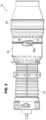
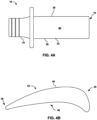
- FIGS. 4A-4C are conceptual diagrams illustrating different views of an example blade, such as blade 16.
- Blade 16 generally includes airfoil 32 attached to stalk 34. Airfoil 32 includes a leading edge 36, a trailing edge 38, a pressure sidewall 40, and a suction sidewall 42. Pressure sidewall 40 is connected to suction sidewall 42 at leading edge 36 and trailing edge 38. Further, blade 16 defines blade tip 19, which is a surface substantially orthogonal to leading edge 36. Blade tip 19 is defined by an edge 46 which extends about the perimeter of the surface of blade tip 19, and separates the surface of blade tip 19 from the adjacent surface of airfoil 32. Leading edge 36, trailing edge 38, pressure sidewall 40, and suction side wall 42 generally extend from stalk 34 to edge 46.
- blade 16 may be a component of a mechanical system including, e.g., a gas turbine engine.
- blade 16 may be compressor blade that imparts kinetic energy into a fluid or a turbine blade that extracts kinetic energy from a moving fluid.
- FIG. 4C is a conceptual diagram further illustrating aspects gas turbine engine 11 with blade 16.
- Gas turbine engine 11 includes blade track 52, which is defined into a surface 54 of abradable coating 23 on static component substrate 22.
- Blade 16 includes abradable tip coating 21, which is described in greater detail below, formed on blade tip 19.
- gas turbine engine 11 As described above, during operation of gas turbine engine 11, blade 16 rotates relative to blade track 52 on blade shroud or other static component 22 in a direction indicated by arrow 60. In general, the power and efficiency of gas turbine engine 11 can be increased by reducing the gap blade track 52 and blade 16, e.g., to reduce or eliminate gas leakage around blade 16.
- gas turbine engine 11, in various examples, is configured to allow abrasive coating 21 on tip 19 of blade 16 to abrade into surface 34 of abradable coating 23 on static component 22, thereby defining blade track 52 which creates a seal between blade track 52 and blade 16.
- Abrasive tip coating 38 which is described in greater detail below, may be provided on blade tip 19 to improve different properties of an underlying blade surface including, e.g., wear, corrosion, hardness, and/or temperature resistance properties of an underlying blade surface. Additionally, or alternatively, a protective coating may be applied to an entire airfoil 32, including blade tip 19, to improve different properties of an underlying blade surface. In some examples, airfoil 32 may receive a coating that reduces or substantially eliminates the effects of oxidation or corrosion on airfoil 32.
- FIG. 5 is an example technique for forming an abrasive coating on a substrate.
- the example technique of FIG. 5 will be described with regard to the formation of abrasive coating 21 on blade tip 19 of blade 16 of gas turbine engine 11 described above.
- the example technique of FIG. 5 may be employed to form any abrasive coating including abrasive particles in a metal matrix material on any suitable substrate surface.
- abrasive coating 21 may be formed on a surface of a blade vane.
- Such an example technique may be employed to form an abrasive coating on the surface of other components of gas turbine engine 11 or components of other systems in which abrasive coatings are desired.
- FIGS. 6A-6C are cross-sectional diagrams of blade 16 that illustrate the various stages throughout the application of abrasive coating 21 using the technique of FIG. 5 .
- abrasive coating 21 may be formed on the outer surface of blade tip 19 of blade 16, where abrasive coating 21 includes a plurality of abrasive particles 68 in metal matrix 69 (62).
- Abrasive coating 21 may be deposited to cover the entire outer surface of blade tip 19 or only a portion of the outer surface of blade tip 19, e.g., the portion of blade tip 19 which contacts opposing surface of abradable coating 23 during operation of engine 11.
- abrasive particles 68 and metal matrix 69 may include one or more of cubic boron nitride particles, carbide particles, metal carbide particles, metal oxide particles, nitride particles, metal nitride particles, such as silicon carbide, aluminum oxide, or silicon nitride.
- abrasive particles 68 may have a particle size of 15 mesh to 40 mesh, 300 mesh or smaller, larger than 60 mesh, or less than 80 mesh. Other particles sizes are contemplated.
- the size of abrasive particles 68 may depend on a number of factors, such as, the thickness 72 of abrasive coating 21 after being deposited, as well as the thickness 76 of abrasive coating 21 after machining and/or the thickness 80 of abrasive coating 21 after machining and etching, as will be described below.
- Abrasive particles 68 may have any suitable shape. As shown in FIG. 6A , e.g., abrasive particles 68 have a relative uniform diamond shape. In other examples, abrasive particles 68 may be non-uniform in shape (and size) and may be shapes other than diamond shape.
- metal matrix 69 may include nickel, titanium, magnesium, cobalt, aluminum, chromium, and alloys thereof.
- Abrasive coating 21 may have any suitable composition, e.g., that allows the coating to function as described herein.
- abrasive coating 21 may include at least approximately 10 volume percent (vol%) of abrasive particles 68, such as, approximately 50 to approximately 80 vol%, or less than approximately 95 vol% of abrasive particles 68.
- Abrasive layer 21 may also include at least approximately 5 vol% of metal matrix 69, such as, approximately 20 to approximately 50 vol%, or less than approximately 90 vol% of metal matrix 69. Other amounts are contemplated.
- Blade 16 may be formed of a material suitable for use in a high-temperature environment.
- blade 16 includes titanium alloys, intermetallics and super alloys including, for example, an alloy based on nickel (Ni), cobalt (Co), Ni/iron (Fe), or the like.
- substrate may also include one or more additives such as titanium (Ti), Co, or aluminum (Al), which may improve the mechanical properties of substrate including, for example, toughness, hardness, temperature stability, corrosion resistance, oxidation resistance, or the like.
- a superalloy may be utilized for substrate, including, for example, those available from Martin-Marietta Corp., Bethesda, MD, under the trade designation MAR-M247; those available from Cannon-Muskegon Corp., Muskegon, MI, under the trade designation CMSX-3, CMSX-4, or CMXS-10; and the like.
- blade 16 may include a ceramic or ceramic matrix composite (CMC) substrate, although a change in bond-type chemistry and/or surface preparation from that used for superalloy substrates may be necessary for ceramic or CMC substrates.
- Blade 16 including a ceramic or CMC substrate may include any useful ceramic material, including, for example, silicon carbide, silicon nitride, alumina, silica, and the like.
- the CMC may further include any desired filler material, and the filler material may include a continuous reinforcement or a discontinuous reinforcement.
- the filler material may include discontinuous whiskers, platelets, or particulates.
- the filler material may include a continuous monofilament or multifilament weave.
- the filler composition, shape, size, and the like may be selected to provide the desired properties to the CMC.
- the filler material may be chosen to increase the toughness of a brittle ceramic matrix.
- the filler may also be chosen to modify a thermal conductivity, electrical conductivity, thermal expansion coefficient, hardness, or the like of the CMC.
- the filler composition may be the same as the ceramic matrix material.
- a silicon carbide matrix may surround silicon carbide whiskers.
- the filler material may include a different composition than the ceramic matrix, such as aluminum silicate fibers in an alumina matrix, or the like.
- One preferred CMC includes silicon carbide continuous fibers embedded in a silicon carbide matrix.
- Some example ceramics and CMCs which may be used for the substrate of blade 16 include ceramics containing Si, such as SiC and Si 3 N 4 ; composites of SiC or Si 3 N 4 and silicon oxynitride or silicon aluminum oxynitride; metal alloys that include Si, such as a molybdenum-silicon alloy (e.g., MoSi 2 ) or niobium-silicon alloys (e.g., NbSi 2 ); and oxide-oxide ceramics, such as an alumina or aluminosilicate matrix with a NEXTEL TM Ceramic Oxide Fiber 720 (available from 3M Co., St. Paul, MN).
- Si such as SiC and Si 3 N 4
- metal alloys that include Si such as a molybdenum-silicon alloy (e.g., MoSi 2 ) or niobium-silicon alloys (e.g., NbSi 2 )
- oxide-oxide ceramics such as an
- abrasive coating 21 is formed on surface of blade tip 19.
- “formed on” and “on” mean a layer or coating that is formed on top of another layer or coating, and encompasses both a first layer or coating formed immediately adjacent a second layer or coating and a first layer or coating formed on top of a second layer or coating with one or more intermediate layers or coatings present between the first and second layers or coatings.
- “formed directly on” and “directly on” denote a layer or coating that is formed immediately adjacent another layer or coating, e.g., there are no intermediate layers or coatings.
- abrasive coating 21 may be directly on substrate.
- one or more coatings or layers of coatings may be between abrasive coating 21 and blade tip 19.
- abrasive coating 21 may have any suitable thickness 72, which may be substantially uniform or non-uniform on blade tip 19. In some examples, thickness 72 may be greater than approximately 44 microns, less than 1000 microns, or approximately 175 to approximately 225 microns. Other thicknesses are contemplated. While FIG. 6A illustrates abrasive coating 21 being formed of a single layer, in other examples, abrasive coating 21 may be formed of multiple layers, e.g., multiple layers deposited sequentially on top of each other until an overall thickness 72 of abrasive coating 21 is achieved. While abrasive coating 21 is shown in FIG. 6A as having thickness 72 that is substantially equal to the thickness of abrasive particles 68, in other examples, thickness 72 may be greater than the thickness of abrasive particles 68.
- Abrasive coating 21 may be formed on blade tip 19 using any suitable coating deposition technique.
- FIG. 6A illustrates an example in which abrasive coating 21 is formed using a directed energy deposition technique. Using such a technique, blade 16 may be masked in some areas to define an exposed surface area, e.g., in the area of blade tip 19, onto which abrasive coating is to be formed.
- Energy source 70 may be directed at the materials of abrasive coating 21, e.g., in the form of powders or wire, on or above the surface of blade tip 19 to melt or sinter at least some of the materials (e.g., the metal matrix material but not the abrasive material) onto the surface of blade tip 19 which then solidify to form abrasive coating 21.
- the sintering or melting and cooling of metal matrix 69 may attach abrasive particles 68 to substrate.
- abrasive coating 21 may be machined to remove a portion of abrasive coating 21 (64).
- Abrasive coating 21 may be machined to a desired shape and thickness. The machining may reduce abrasive coating 21 to thickness 76 from thickness 72 of abrasive coating 21 when initially formed. As such, thickness 76 may be less than thickness 72. In some examples, thickness 76 may be approximately 10% to approximately 95%, such as, approximately 50% to approximately 90% of thickness 72. In some examples, thickness 76 may be greater than approximately 20 microns, less than 800 microns, or approximately 50 microns to approximately 300 microns.
- Any suitable machining process may be used to machine abrasive coating 21, such as, diamond grinding, laser ablation, electrical discharge machining.
- the machining process may remove portions of metal matrix 69, abrasive particles 68, or both from abrasive coating 21.
- Abrasive coating 21 may be machined such that the machined abrasive coating 21 defines a desired thickness profile.
- the layer thickness profile may refer to the thickness of abrasive coating 21 over the surface of blade tip 19, e.g., rather than the thickness at only one point on the surface of blade tip 19.
- the layer thickness profile of abrasive coating 21 after machining may be such that coating 21 is substantially uniform in thickness after machining or non-uniform in thickness.
- a layer thickness profile for abrasive coating 21 may be provided such that abrasive coating 21 defines a substantially continuous and even seal between coating 21 and abradable coating 23 during operation.
- abradable coating 23 may be machined to a layer thickness profile that defines a substantially equal distance between the outer surface of abrasive coating 21 and the outer surface of blade track 52 when abrasive coating 21 abrades into abradable coating 23,e.g., during operation of engine 11.
- the abrasive coating thickness profile may refer to the thickness profile defined by the combination of abrasive coating 21 and the part on which abrasive coating 21 is applied.
- the abrasive coating thickness profile may be defined to achieve a substantially uniform blade height (the overall height of blade 16 and coating 21) when rubbing or otherwise abrading into abradable coating 23 (e.g., rather than simply a uniform coating thickness).
- a gas turbine engine 11 include a plurality of blades 16, each blade may be different in height before coating.
- the machining process may allow the abrasive coating 21 to be machined to a thickness profile that may be unique to each blade such that the overall thickness of each of the coated blades results in coated blades having a substantially uniform installed height, e.g., to prevent excess leakage around "shorter" or uneven uncoated blades.
- the machined abrasive coating thickness profile may result in the coated blades having substantially the same height, e.g., to allow for a substantially uniform seal with abradable coating 23 during operation.
- abrasive coating 21 may be surface etched to remove a portion of metal matrix 69 from around abrasive particles 68 such that the abrasive particles 68 are exposed and protrude out of metal matrix 69 (66).
- one or more individual particles of plurality of abrasive particles 68 may be covered entirely by metal matrix 69 after the initial formation of abrasive coating 21 (62) and machining of abrasive coating 21 (64).
- the etching of abrasive layer 21 to remove a portion of metal matrix 69 (66) may expose at least a portion of the covered particles 68, e.g., to increase the abrasiveness of abrasive coating 21.
- the removal of metal matrix 69 via etching may also further expose surfaces of individual particles 68 that are partially exposed following formation and machining of abrasive layer 21.
- portions of blade 16 may be masked to protect the substrate during the etching process. Any suitable etching process may be used.
- abrasive coating 21 (along with masked portions of blade 16) may be immersed in an acid or electrolyte solution (e.g., for electrolytic etching).
- the portion of metal matrix 69 at or near the surface of abrasive coating 21 may be selectively removed, e.g., via etching such as electrolytic etching in which the etching process includes the use of electricity or etching including immersion without the application of electricity, to reveal cutting/abrading surfaces of abrasive particles 68, as described herein.
- any suitable acid or electrolyte may be used based on the type of metal matrix 69.
- Different etchants may be suitable for different materials (e.g., since the various examples types of metal matrix 69 may have different corrosion resistance).
- the etching process may remove only metal matrix 69 and not abrasive particles 68 from abrasive coating 21. Following the removal of a portion of metal matrix 69, the masking of blade 16 may be removed.
- the removal of the metal matrix may reduce the thickness of metal matrix 69 to an etched thickness 80.
- the etching may remove the same amount of metal matrix 69 over the entire surface abrasive coating 21 or may remove more metal matrix 69 from some portions of coating 21 compared to other portions.
- thickness 80 of metal matrix 69 may be approximately 10% to approximately 95%, such as, approximately 60% to approximately 90% of thickness 76.
- thickness 80 may be greater than approximately 20 microns, less than 760 microns, or approximately 12 microns to approximately 700 microns. Thickness 80 may be substantially uniform or non-uniform.
- metal matrix 69 may have thickness 80 that is less than the machine thickness 76 following the etching, particles 68 may remain at substantially the same thickness 76 as the machined layer thickness. As such, following etching, distance 82 particles 68 protrude from metal matrix 69 may be substantially equal to the difference between thickness 76 and post etching metal matrix thickness 80, as shown in FIG. 6C . In some examples, particles 68 protrude distance 82 of greater than approximately 1 micron, less than 760 microns, or approximately 8 microns to approximately 630 microns.
- cutting/abrasive surface of coating 21 may have increased cutting/abrasion effectiveness, e.g., as compared to an abrasive layer that is formed without machining or removal of a portion of the metal matrix, or only machined.
- the removal of metal matrix 69 may additionally or alternatively reduced rub on metal matrix 69 of abrasive coating 21 when abrasive coating 21 abrades abradable coating 23. This reduces frictional heating, improving strength and durability of coating.
- abrasive coating 21 is shown in FIGS. 6A-6C as being formed directly on turbine blade 16, in other examples one or more additional layers may be formed between abrasive coating 21 and blade 16.
- interlayers may be used to modify the heat transfer from the coating to the substrate. Interlayers may be used to better match thermal expansion between the abrasive coating and the substrate.
- blade 16 may be assembled as a component of engine 11. During operation of engine 11, abrasive coating 21 abrades into abradable coating 23 in the manner described above.
- abrasive coating 21 on blade tip 19 of blade 16 of gas turbine engine 11
- such an abrasive coating may be employed on a knife seal ring and/or compressor blade of a gas turbine engine.
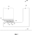
- FIG. 7 is a cross-sectional view of a knife seal 210 configured for use in a gas turbine engine.
- a knife seal 210 may be an example application of an example abrasive coating for a gas turbine engine component.
- the annular runner 212 may be made of an abradable material.
- knife rings 231, 232, and 233 may come in contact with the abradable material of the annular runner 212. The contact between knife ring 231, 232, and 233 and annular runner 212 abrades annular 212 and works to form a seal, effectively sealing airflow from the gas turbine engine.
- abrasive coating 220 which may be the same or substantially similar to that of abrasive coating 21 described above, defining knife edge 241, 242, 243 may allow the knife edge 241, 242, 243 to contact the abradable material on the annular runner 212 creating a more wear resistant seal. A more wear resistant seal will allow the part to stay in use for longer durations without needing replacement.
- the annular runner 212 may be coupled to a static structure 224 included in a gas turbine engine.
- the knife rings 231, 232, 233 may each have an attachment edge 251, 252, 253, opposite the knife edges 241, 242, 243.
- the attachment edges 251, 252, 253 may be coupled to a rotor 226 included in a gas turbine engine so that the knife rings 231, 232, 233 rotate with the rotor 226 about an axis 228 during operation of the gas turbine engine.
- knife seal 210 may be produced using the example techniques described herein for forming an abrasive coating on a gas turbine engine component, as described with regard to FIG. 5 .
- Knife seal 210 may be configured for use in a gas turbine engine and having a coating 220 is shown in FIG. 7 .
- the knife seal 210 may include an annular runner 212 and a plurality of knife rings 231, 232, 233.
- the plurality of knife rings 231, 232, 233 may be arranged to contact the annular runner 212 to form a seal between the annular runner 212 and the knife rings 231, 232, 233 during operation of the gas turbine engine.
- the knife seal 210 may also include the coating 220 applied to a knife edge 241, 242, 243 of each knife ring 231, 232, 233 at the interface of the annular runner 212 and the knife rings 231, 232, 233.
- Abrasive coating 220 may be similar to abrasive coating 21 described above and may protect the knife edges 241, 242, 243 of the knife rings 231, 232, 233 during operation of the gas turbine engine.
- the coating 220 may include a metal matrix and a plurality of abrasive particles.
- the metal matrix may be joined to the knife edges 241, 242, 243 of the knife rings 231, 232, 233 and may suspend the abrasive particles in place relative to the knife rings 231, 232, 233.
- Examples of gas turbine engines including knife seals may include one or more examples described in U.S. Patent Application No.: 14/734,834 by Shuck (U.S. Patent Publication US 2015/0377039 ).
Landscapes
- Engineering & Computer Science (AREA)
- Chemical & Material Sciences (AREA)
- Materials Engineering (AREA)
- Mechanical Engineering (AREA)
- General Engineering & Computer Science (AREA)
- Organic Chemistry (AREA)
- Ceramic Engineering (AREA)
- Manufacturing & Machinery (AREA)
- Metallurgy (AREA)
- Composite Materials (AREA)
- Inorganic Chemistry (AREA)
- Turbine Rotor Nozzle Sealing (AREA)
- Polishing Bodies And Polishing Tools (AREA)
Claims (10)
- Procédé comprenant :la formation (62) d'un système de revêtement abrasif sur un substrat, le système de revêtement abrasif comprenant un revêtement abrasif (21) comprenant une pluralité de particules abrasives (68) dans une matrice métallique (69), ladite formation du système de revêtement abrasif sur le substrat comprenant le dépôt de la pluralité de particules abrasives (68) et de la matrice métallique (69) sur le substrat ;l'usinage (64) du revêtement abrasif (21) sur le substrat pour définir un revêtement abrasif usiné comportant un profil d'épaisseur de revêtement abrasif ; etla gravure (66) d'une surface externe du revêtement abrasif usiné pour retirer une partie de la matrice métallique (69) et former une matrice métallique gravée de sorte que les particules abrasives (68) fassent saillie à partir de la matrice métallique (69) ;ledit substrat comprenant une aube (16) d'un moteur à turbine à gaz (11), ledit revêtement abrasif (21) étant formé sur une extrémité d'aube (19) de l'aube (16), et ledit système de revêtement abrasif de l'extrémité d'aube (19) étant configuré pour abraser une couche abradable (23) d'une piste d'aube (52) durant le fonctionnement du moteur à turbine à gaz (11), le procédé étant caractérisé en ce qu'un dépôt d'énergie dirigé est utilisé pour déposer la pluralité de particules abrasives (68) et la matrice métallique (69), pendant la formation du système de revêtement abrasif sur le substrat.
- Procédé selon la revendication 1, lesdites particules abrasives (68) faisant saillie de 1 micron à 760 microns à partir de la matrice métallique gravée.
- Procédé selon la revendication 1 ou 2, ladite matrice métallique gravée définissant une épaisseur (80) de 20 microns à 760 microns.
- Procédé selon l'une quelconque des revendications 1 à 3, ledit revêtement abrasif (21) définissant une épaisseur (72) de 44 microns à 1000 microns avant l'usinage.
- Procédé selon l'une quelconque des revendications 1 à 4, lesdites particules abrasives (68) comprenant au moins l'une des particules de nitrure de bore cubique, des particules de carbure métallique, des particules de nitrure métallique et des particules d'oxyde métallique.
- Procédé selon l'une quelconque des revendications 1 à 5, ladite matrice métallique (69) comprenant au moins l'un du nickel, du titane, du magnésium, du cobalt, de l'aluminium, du chrome ou de leurs alliages.
- Procédé selon l'une quelconque des revendications 1 à 6, ladite gravure de la surface externe du revêtement abrasif usiné comprenant au moins l'une de la gravure électrolytique de la surface externe du revêtement abrasif usiné et de la gravure par immersion de la surface externe du revêtement dans un acide.
- Procédé selon la revendication 1, ledit profil d'épaisseur de revêtement abrasif du revêtement abrasif usiné étant défini de sorte qu'un joint d'étanchéité sensiblement continu soit formé entre l'aube (16) et la piste d'aube (52) durant le fonctionnement après que le revêtement abrasif (21) a abrasé la couche abradable (23) de la piste d'aube (52) durant le fonctionnement du moteur à turbine à gaz (11).
- Procédé selon l'une quelconque des revendications 1 à 8, ledit substrat comprenant un substrat en superalliage.
- Procédé selon l'une quelconque des revendications 1 à 9, ledit revêtement abrasif (21) comprenant une pluralité de couches abrasives, chaque couche abrasive comprenant la pluralité de particules abrasives (68) dans la matrice métallique (69), ladite formation du système de revêtement abrasif sur le substrat comprenant la formation séquentielle de la pluralité de couches abrasives sur le substrat.
Applications Claiming Priority (1)
| Application Number | Priority Date | Filing Date | Title |
|---|---|---|---|
| US16/250,752 US10954803B2 (en) | 2019-01-17 | 2019-01-17 | Abrasive coating for high temperature mechanical systems |
Publications (3)
| Publication Number | Publication Date |
|---|---|
| EP3683017A2 EP3683017A2 (fr) | 2020-07-22 |
| EP3683017A3 EP3683017A3 (fr) | 2020-10-07 |
| EP3683017B1 true EP3683017B1 (fr) | 2023-05-17 |
Family
ID=68916220
Family Applications (1)
| Application Number | Title | Priority Date | Filing Date |
|---|---|---|---|
| EP19215750.1A Active EP3683017B1 (fr) | 2019-01-17 | 2019-12-12 | Revêtement abrasif pour systèmes mécaniques à haute température et systèmes mécaniques à haute température avec un revêtement abrasif |
Country Status (3)
| Country | Link |
|---|---|
| US (1) | US10954803B2 (fr) |
| EP (1) | EP3683017B1 (fr) |
| CA (1) | CA3068676A1 (fr) |
Families Citing this family (4)
| Publication number | Priority date | Publication date | Assignee | Title |
|---|---|---|---|---|
| US12311439B2 (en) | 2020-09-23 | 2025-05-27 | Rolls-Royce Corporation | Metal matrix composite seal using directed energy deposition |
| CN114000011B (zh) * | 2021-09-28 | 2022-06-28 | 淮阴工学院 | 一种异质界面增强镍基合金及其成形方法 |
| US12571311B2 (en) | 2022-10-25 | 2026-03-10 | General Electric Company | Erosion-shielded turbine blades and methods of manufacturing the same |
| US12129769B2 (en) * | 2022-10-25 | 2024-10-29 | Ge Infrastructure Technology Llc | Erosion-shielded turbine blades and methods of manufacturing the same |
Family Cites Families (36)
| Publication number | Priority date | Publication date | Assignee | Title |
|---|---|---|---|---|
| US4060250A (en) * | 1976-11-04 | 1977-11-29 | De Laval Turbine Inc. | Rotor seal element with heat resistant alloy coating |
| US4148494A (en) * | 1977-12-21 | 1979-04-10 | General Electric Company | Rotary labyrinth seal member |
| US4522692A (en) * | 1983-07-26 | 1985-06-11 | United Technologies Corporation | Electrochemical machining a workpiece uniformly using a porous electrode |
| US4680199A (en) * | 1986-03-21 | 1987-07-14 | United Technologies Corporation | Method for depositing a layer of abrasive material on a substrate |
| US4741973A (en) * | 1986-12-15 | 1988-05-03 | United Technologies Corporation | Silicon carbide abrasive particles having multilayered coating |
| US4936745A (en) * | 1988-12-16 | 1990-06-26 | United Technologies Corporation | Thin abradable ceramic air seal |
| US5104293A (en) * | 1990-07-16 | 1992-04-14 | United Technologies Corporation | Method for applying abrasive layers to blade surfaces |
| US5264011A (en) | 1992-09-08 | 1993-11-23 | General Motors Corporation | Abrasive blade tips for cast single crystal gas turbine blades |
| US5359770A (en) | 1992-09-08 | 1994-11-01 | General Motors Corporation | Method for bonding abrasive blade tips to the tip of a gas turbine blade |
| US5486281A (en) | 1993-10-15 | 1996-01-23 | United Technologies Corporation | Method for CBN tipping of HPC integrally bladed rotors |
| US5603603A (en) | 1993-12-08 | 1997-02-18 | United Technologies Corporation | Abrasive blade tip |
| DE4432998C1 (de) * | 1994-09-16 | 1996-04-04 | Mtu Muenchen Gmbh | Anstreifbelag für metallische Triebwerkskomponente und Herstellungsverfahren |
| US5932356A (en) * | 1996-03-21 | 1999-08-03 | United Technologies Corporation | Abrasive/abradable gas path seal system |
| US5704759A (en) * | 1996-10-21 | 1998-01-06 | Alliedsignal Inc. | Abrasive tip/abradable shroud system and method for gas turbine compressor clearance control |
| US5935407A (en) | 1997-11-06 | 1999-08-10 | Chromalloy Gas Turbine Corporation | Method for producing abrasive tips for gas turbine blades |
| US6190124B1 (en) * | 1997-11-26 | 2001-02-20 | United Technologies Corporation | Columnar zirconium oxide abrasive coating for a gas turbine engine seal system |
| DE10347981A1 (de) * | 2003-10-15 | 2005-07-07 | Gühring, Jörg, Dr. | Verschleißschutzschicht für spanabhebende Werkzeuge, insbesondere für rotierende Zerspanungswerkzeuge |
| US20050129511A1 (en) * | 2003-12-11 | 2005-06-16 | Siemens Westinghouse Power Corporation | Turbine blade tip with optimized abrasive |
| GB2449862B (en) | 2007-06-05 | 2009-09-16 | Rolls Royce Plc | Method for producing abrasive tips for gas turbine blades |
| JP5101317B2 (ja) * | 2008-01-25 | 2012-12-19 | 三菱重工業株式会社 | シール構造 |
| JP5809053B2 (ja) * | 2008-07-03 | 2015-11-10 | スリーエム イノベイティブ プロパティズ カンパニー | 固定研磨粒子及びそれから作製される物品 |
| WO2010121025A1 (fr) * | 2009-04-17 | 2010-10-21 | 3M Innovative Properties Company | Article de transfert de particules métalliques, substrat modifié par un métal et procédé de fabrication et d'utilisation de ceux-ci |
| DE102009053954A1 (de) * | 2009-11-19 | 2011-06-09 | Siemens Aktiengesellschaft | Labyrinthdichtung und Verfahren zum Herstellen einer Labyrinthdichtung |
| KR20140018880A (ko) * | 2011-01-26 | 2014-02-13 | 쓰리엠 이노베이티브 프로퍼티즈 컴파니 | 복제된 미세구조화 배킹을 갖는 연마재 물품 및 그것을 이용하는 방법 |
| US20160356165A1 (en) * | 2014-02-14 | 2016-12-08 | United Technologies Corporation | Abrasive Tip Blade Manufacture Methods |
| GB201405032D0 (en) * | 2014-03-20 | 2014-05-07 | Enbio Ltd | Method for producing corrosion-inhibiting coatings |
| US9957819B2 (en) * | 2014-03-28 | 2018-05-01 | United Technologies Corporation | Abrasive tip blade manufacture methods |
| US10072506B2 (en) * | 2014-06-30 | 2018-09-11 | Rolls-Royce Corporation | Coated gas turbine engine components |
| WO2016061585A1 (fr) | 2014-10-17 | 2016-04-21 | Applied Materials, Inc. | Tampons de polissage produits par un procédé de fabrication d'additifs |
| SG10201700339YA (en) | 2016-02-29 | 2017-09-28 | Rolls Royce Corp | Directed energy deposition for processing gas turbine engine components |
| US10670045B2 (en) * | 2016-04-29 | 2020-06-02 | Raytheon Technologies Corporation | Abrasive blade tips with additive layer resistant to clogging |
| US10697464B2 (en) * | 2016-07-29 | 2020-06-30 | Raytheon Technologies Corporation | Abradable material |
| US10294962B2 (en) * | 2017-06-30 | 2019-05-21 | United Technologies Corporation | Turbine engine seal for high erosion environment |
| US11149744B2 (en) * | 2017-09-19 | 2021-10-19 | Raytheon Technologies Corporation | Turbine engine seal for high erosion environment |
| US20190186281A1 (en) * | 2017-12-20 | 2019-06-20 | United Technologies Corporation | Compressor abradable seal with improved solid lubricant retention |
| US11028721B2 (en) * | 2018-07-19 | 2021-06-08 | Ratheon Technologies Corporation | Coating to improve oxidation and corrosion resistance of abrasive tip system |
-
2019
- 2019-01-17 US US16/250,752 patent/US10954803B2/en active Active
- 2019-12-12 EP EP19215750.1A patent/EP3683017B1/fr active Active
-
2020
- 2020-01-17 CA CA3068676A patent/CA3068676A1/fr active Pending
Also Published As
| Publication number | Publication date |
|---|---|
| US20200232333A1 (en) | 2020-07-23 |
| CA3068676A1 (fr) | 2020-07-17 |
| EP3683017A3 (fr) | 2020-10-07 |
| US10954803B2 (en) | 2021-03-23 |
| EP3683017A2 (fr) | 2020-07-22 |
Similar Documents
| Publication | Publication Date | Title |
|---|---|---|
| CN109424369B (zh) | 包括涂层系统的涡轮叶片和形成涡轮叶片的方法 | |
| EP2925971B1 (fr) | Dispositifs d'étanchéité destinés à être utilisés dans des turbomachines et leurs procédés de fabrication | |
| JP4322980B2 (ja) | ガス・タービン・エンジンのシール機構 | |
| US4936745A (en) | Thin abradable ceramic air seal | |
| EP3683017B1 (fr) | Revêtement abrasif pour systèmes mécaniques à haute température et systèmes mécaniques à haute température avec un revêtement abrasif | |
| US9581041B2 (en) | Abradable ceramic coatings and coating systems | |
| US8650753B2 (en) | Seal and a method of manufacturing a seal | |
| CA2686332C (fr) | Couche abradable comprenant du silicate de terre rare | |
| US6616410B2 (en) | Oxidation resistant and/or abrasion resistant squealer tip and method for casting same | |
| EP2540961B1 (fr) | Extrémité d'aube en matériau abrasif | |
| US6884470B2 (en) | Application method for abradable material | |
| US20120099971A1 (en) | Self dressing, mildly abrasive coating for clearance control | |
| JP6313762B2 (ja) | 低表面粗度を有する材料からなる摩耗性コーティング | |
| US20180087387A1 (en) | Compositions and methods for coating metal turbine blade tips | |
| EP3456928A1 (fr) | Joint d'étanchéité de moteur à turbine pour environnement d'érosion élevée | |
| EP3816401A1 (fr) | Ensemble de rotor pour le meulage à l'intérieur de machine d'un élément de virole et procédé d'utilisation associé | |
| EP3611350B1 (fr) | Pointes de lame de turbine abrasives présentant une meilleure résistance à l'oxydation | |
| EP4112883A1 (fr) | Système d'adressage d'usure de rail d'extrémité de pale de turbine lors du frottement et du refroidissement | |
| EP3901416A1 (fr) | Procédé et configuration matérielle de fabrication de pointes de pale abrasives de compresseur haut pression résistant à la corrosion à chaud |
Legal Events
| Date | Code | Title | Description |
|---|---|---|---|
| PUAI | Public reference made under article 153(3) epc to a published international application that has entered the european phase |
Free format text: ORIGINAL CODE: 0009012 |
|
| STAA | Information on the status of an ep patent application or granted ep patent |
Free format text: STATUS: THE APPLICATION HAS BEEN PUBLISHED |
|
| AK | Designated contracting states |
Kind code of ref document: A2 Designated state(s): AL AT BE BG CH CY CZ DE DK EE ES FI FR GB GR HR HU IE IS IT LI LT LU LV MC MK MT NL NO PL PT RO RS SE SI SK SM TR |
|
| AX | Request for extension of the european patent |
Extension state: BA ME |
|
| PUAL | Search report despatched |
Free format text: ORIGINAL CODE: 0009013 |
|
| AK | Designated contracting states |
Kind code of ref document: A3 Designated state(s): AL AT BE BG CH CY CZ DE DK EE ES FI FR GB GR HR HU IE IS IT LI LT LU LV MC MK MT NL NO PL PT RO RS SE SI SK SM TR |
|
| AX | Request for extension of the european patent |
Extension state: BA ME |
|
| RIC1 | Information provided on ipc code assigned before grant |
Ipc: B24D 18/00 20060101ALI20200903BHEP Ipc: B33Y 80/00 20150101ALI20200903BHEP Ipc: B24D 3/06 20060101AFI20200903BHEP Ipc: F01D 11/12 20060101ALI20200903BHEP Ipc: B33Y 10/00 20150101ALI20200903BHEP |
|
| STAA | Information on the status of an ep patent application or granted ep patent |
Free format text: STATUS: REQUEST FOR EXAMINATION WAS MADE |
|
| 17P | Request for examination filed |
Effective date: 20210330 |
|
| RBV | Designated contracting states (corrected) |
Designated state(s): AL AT BE BG CH CY CZ DE DK EE ES FI FR GB GR HR HU IE IS IT LI LT LU LV MC MK MT NL NO PL PT RO RS SE SI SK SM TR |
|
| REG | Reference to a national code |
Ref country code: DE Ref legal event code: R079 Free format text: PREVIOUS MAIN CLASS: B24D0003060000 Ipc: F01D0011000000 Ref country code: DE Ref legal event code: R079 Ref document number: 602019029046 Country of ref document: DE Free format text: PREVIOUS MAIN CLASS: B24D0003060000 Ipc: F01D0011000000 |
|
| GRAP | Despatch of communication of intention to grant a patent |
Free format text: ORIGINAL CODE: EPIDOSNIGR1 |
|
| STAA | Information on the status of an ep patent application or granted ep patent |
Free format text: STATUS: GRANT OF PATENT IS INTENDED |
|
| RIC1 | Information provided on ipc code assigned before grant |
Ipc: F01D 11/12 20060101ALI20221130BHEP Ipc: B33Y 80/00 20150101ALI20221130BHEP Ipc: B24D 18/00 20060101ALI20221130BHEP Ipc: B24D 3/06 20060101ALI20221130BHEP Ipc: F01D 11/00 20060101AFI20221130BHEP |
|
| GRAJ | Information related to disapproval of communication of intention to grant by the applicant or resumption of examination proceedings by the epo deleted |
Free format text: ORIGINAL CODE: EPIDOSDIGR1 |
|
| STAA | Information on the status of an ep patent application or granted ep patent |
Free format text: STATUS: REQUEST FOR EXAMINATION WAS MADE |
|
| INTG | Intention to grant announced |
Effective date: 20221220 |
|
| RIN1 | Information on inventor provided before grant (corrected) |
Inventor name: SHUCK, QUINLAN |
|
| GRAP | Despatch of communication of intention to grant a patent |
Free format text: ORIGINAL CODE: EPIDOSNIGR1 |
|
| STAA | Information on the status of an ep patent application or granted ep patent |
Free format text: STATUS: GRANT OF PATENT IS INTENDED |
|
| INTC | Intention to grant announced (deleted) | ||
| INTG | Intention to grant announced |
Effective date: 20230206 |
|
| GRAS | Grant fee paid |
Free format text: ORIGINAL CODE: EPIDOSNIGR3 |
|
| GRAA | (expected) grant |
Free format text: ORIGINAL CODE: 0009210 |
|
| STAA | Information on the status of an ep patent application or granted ep patent |
Free format text: STATUS: THE PATENT HAS BEEN GRANTED |
|
| AK | Designated contracting states |
Kind code of ref document: B1 Designated state(s): AL AT BE BG CH CY CZ DE DK EE ES FI FR GB GR HR HU IE IS IT LI LT LU LV MC MK MT NL NO PL PT RO RS SE SI SK SM TR |
|
| REG | Reference to a national code |
Ref country code: GB Ref legal event code: FG4D |
|
| REG | Reference to a national code |
Ref country code: DE Ref legal event code: R096 Ref document number: 602019029046 Country of ref document: DE |
|
| REG | Reference to a national code |
Ref country code: CH Ref legal event code: EP |
|
| REG | Reference to a national code |
Ref country code: IE Ref legal event code: FG4D |
|
| REG | Reference to a national code |
Ref country code: AT Ref legal event code: REF Ref document number: 1568442 Country of ref document: AT Kind code of ref document: T Effective date: 20230615 |
|
| P01 | Opt-out of the competence of the unified patent court (upc) registered |
Effective date: 20230528 |
|
| REG | Reference to a national code |
Ref country code: LT Ref legal event code: MG9D |
|
| REG | Reference to a national code |
Ref country code: NL Ref legal event code: MP Effective date: 20230517 |
|
| REG | Reference to a national code |
Ref country code: AT Ref legal event code: MK05 Ref document number: 1568442 Country of ref document: AT Kind code of ref document: T Effective date: 20230517 |
|
| PG25 | Lapsed in a contracting state [announced via postgrant information from national office to epo] |
Ref country code: SE Free format text: LAPSE BECAUSE OF FAILURE TO SUBMIT A TRANSLATION OF THE DESCRIPTION OR TO PAY THE FEE WITHIN THE PRESCRIBED TIME-LIMIT Effective date: 20230517 Ref country code: PT Free format text: LAPSE BECAUSE OF FAILURE TO SUBMIT A TRANSLATION OF THE DESCRIPTION OR TO PAY THE FEE WITHIN THE PRESCRIBED TIME-LIMIT Effective date: 20230918 Ref country code: NO Free format text: LAPSE BECAUSE OF FAILURE TO SUBMIT A TRANSLATION OF THE DESCRIPTION OR TO PAY THE FEE WITHIN THE PRESCRIBED TIME-LIMIT Effective date: 20230817 Ref country code: NL Free format text: LAPSE BECAUSE OF FAILURE TO SUBMIT A TRANSLATION OF THE DESCRIPTION OR TO PAY THE FEE WITHIN THE PRESCRIBED TIME-LIMIT Effective date: 20230517 Ref country code: ES Free format text: LAPSE BECAUSE OF FAILURE TO SUBMIT A TRANSLATION OF THE DESCRIPTION OR TO PAY THE FEE WITHIN THE PRESCRIBED TIME-LIMIT Effective date: 20230517 Ref country code: AT Free format text: LAPSE BECAUSE OF FAILURE TO SUBMIT A TRANSLATION OF THE DESCRIPTION OR TO PAY THE FEE WITHIN THE PRESCRIBED TIME-LIMIT Effective date: 20230517 |
|
| PG25 | Lapsed in a contracting state [announced via postgrant information from national office to epo] |
Ref country code: RS Free format text: LAPSE BECAUSE OF FAILURE TO SUBMIT A TRANSLATION OF THE DESCRIPTION OR TO PAY THE FEE WITHIN THE PRESCRIBED TIME-LIMIT Effective date: 20230517 Ref country code: PL Free format text: LAPSE BECAUSE OF FAILURE TO SUBMIT A TRANSLATION OF THE DESCRIPTION OR TO PAY THE FEE WITHIN THE PRESCRIBED TIME-LIMIT Effective date: 20230517 Ref country code: LV Free format text: LAPSE BECAUSE OF FAILURE TO SUBMIT A TRANSLATION OF THE DESCRIPTION OR TO PAY THE FEE WITHIN THE PRESCRIBED TIME-LIMIT Effective date: 20230517 Ref country code: LT Free format text: LAPSE BECAUSE OF FAILURE TO SUBMIT A TRANSLATION OF THE DESCRIPTION OR TO PAY THE FEE WITHIN THE PRESCRIBED TIME-LIMIT Effective date: 20230517 Ref country code: IS Free format text: LAPSE BECAUSE OF FAILURE TO SUBMIT A TRANSLATION OF THE DESCRIPTION OR TO PAY THE FEE WITHIN THE PRESCRIBED TIME-LIMIT Effective date: 20230917 Ref country code: HR Free format text: LAPSE BECAUSE OF FAILURE TO SUBMIT A TRANSLATION OF THE DESCRIPTION OR TO PAY THE FEE WITHIN THE PRESCRIBED TIME-LIMIT Effective date: 20230517 Ref country code: GR Free format text: LAPSE BECAUSE OF FAILURE TO SUBMIT A TRANSLATION OF THE DESCRIPTION OR TO PAY THE FEE WITHIN THE PRESCRIBED TIME-LIMIT Effective date: 20230818 |
|
| PG25 | Lapsed in a contracting state [announced via postgrant information from national office to epo] |
Ref country code: FI Free format text: LAPSE BECAUSE OF FAILURE TO SUBMIT A TRANSLATION OF THE DESCRIPTION OR TO PAY THE FEE WITHIN THE PRESCRIBED TIME-LIMIT Effective date: 20230517 |
|
| PG25 | Lapsed in a contracting state [announced via postgrant information from national office to epo] |
Ref country code: SK Free format text: LAPSE BECAUSE OF FAILURE TO SUBMIT A TRANSLATION OF THE DESCRIPTION OR TO PAY THE FEE WITHIN THE PRESCRIBED TIME-LIMIT Effective date: 20230517 |
|
| PG25 | Lapsed in a contracting state [announced via postgrant information from national office to epo] |
Ref country code: SM Free format text: LAPSE BECAUSE OF FAILURE TO SUBMIT A TRANSLATION OF THE DESCRIPTION OR TO PAY THE FEE WITHIN THE PRESCRIBED TIME-LIMIT Effective date: 20230517 Ref country code: SK Free format text: LAPSE BECAUSE OF FAILURE TO SUBMIT A TRANSLATION OF THE DESCRIPTION OR TO PAY THE FEE WITHIN THE PRESCRIBED TIME-LIMIT Effective date: 20230517 Ref country code: RO Free format text: LAPSE BECAUSE OF FAILURE TO SUBMIT A TRANSLATION OF THE DESCRIPTION OR TO PAY THE FEE WITHIN THE PRESCRIBED TIME-LIMIT Effective date: 20230517 Ref country code: EE Free format text: LAPSE BECAUSE OF FAILURE TO SUBMIT A TRANSLATION OF THE DESCRIPTION OR TO PAY THE FEE WITHIN THE PRESCRIBED TIME-LIMIT Effective date: 20230517 Ref country code: DK Free format text: LAPSE BECAUSE OF FAILURE TO SUBMIT A TRANSLATION OF THE DESCRIPTION OR TO PAY THE FEE WITHIN THE PRESCRIBED TIME-LIMIT Effective date: 20230517 Ref country code: CZ Free format text: LAPSE BECAUSE OF FAILURE TO SUBMIT A TRANSLATION OF THE DESCRIPTION OR TO PAY THE FEE WITHIN THE PRESCRIBED TIME-LIMIT Effective date: 20230517 |
|
| REG | Reference to a national code |
Ref country code: DE Ref legal event code: R097 Ref document number: 602019029046 Country of ref document: DE |
|
| PLBE | No opposition filed within time limit |
Free format text: ORIGINAL CODE: 0009261 |
|
| STAA | Information on the status of an ep patent application or granted ep patent |
Free format text: STATUS: NO OPPOSITION FILED WITHIN TIME LIMIT |
|
| 26N | No opposition filed |
Effective date: 20240220 |
|
| PG25 | Lapsed in a contracting state [announced via postgrant information from national office to epo] |
Ref country code: SI Free format text: LAPSE BECAUSE OF FAILURE TO SUBMIT A TRANSLATION OF THE DESCRIPTION OR TO PAY THE FEE WITHIN THE PRESCRIBED TIME-LIMIT Effective date: 20230517 |
|
| PG25 | Lapsed in a contracting state [announced via postgrant information from national office to epo] |
Ref country code: SI Free format text: LAPSE BECAUSE OF FAILURE TO SUBMIT A TRANSLATION OF THE DESCRIPTION OR TO PAY THE FEE WITHIN THE PRESCRIBED TIME-LIMIT Effective date: 20230517 Ref country code: IT Free format text: LAPSE BECAUSE OF FAILURE TO SUBMIT A TRANSLATION OF THE DESCRIPTION OR TO PAY THE FEE WITHIN THE PRESCRIBED TIME-LIMIT Effective date: 20230517 |
|
| REG | Reference to a national code |
Ref country code: DE Ref legal event code: R119 Ref document number: 602019029046 Country of ref document: DE |
|
| PG25 | Lapsed in a contracting state [announced via postgrant information from national office to epo] |
Ref country code: LU Free format text: LAPSE BECAUSE OF NON-PAYMENT OF DUE FEES Effective date: 20231212 |
|
| PG25 | Lapsed in a contracting state [announced via postgrant information from national office to epo] |
Ref country code: MC Free format text: LAPSE BECAUSE OF FAILURE TO SUBMIT A TRANSLATION OF THE DESCRIPTION OR TO PAY THE FEE WITHIN THE PRESCRIBED TIME-LIMIT Effective date: 20230517 |
|
| GBPC | Gb: european patent ceased through non-payment of renewal fee |
Effective date: 20231212 |
|
| REG | Reference to a national code |
Ref country code: BE Ref legal event code: MM Effective date: 20231231 |
|
| PG25 | Lapsed in a contracting state [announced via postgrant information from national office to epo] |
Ref country code: MC Free format text: LAPSE BECAUSE OF FAILURE TO SUBMIT A TRANSLATION OF THE DESCRIPTION OR TO PAY THE FEE WITHIN THE PRESCRIBED TIME-LIMIT Effective date: 20230517 Ref country code: LU Free format text: LAPSE BECAUSE OF NON-PAYMENT OF DUE FEES Effective date: 20231212 |
|
| REG | Reference to a national code |
Ref country code: IE Ref legal event code: MM4A |
|
| PG25 | Lapsed in a contracting state [announced via postgrant information from national office to epo] |
Ref country code: DE Free format text: LAPSE BECAUSE OF NON-PAYMENT OF DUE FEES Effective date: 20240702 Ref country code: IE Free format text: LAPSE BECAUSE OF NON-PAYMENT OF DUE FEES Effective date: 20231212 |
|
| PG25 | Lapsed in a contracting state [announced via postgrant information from national office to epo] |
Ref country code: GB Free format text: LAPSE BECAUSE OF NON-PAYMENT OF DUE FEES Effective date: 20231212 |
|
| PG25 | Lapsed in a contracting state [announced via postgrant information from national office to epo] |
Ref country code: BE Free format text: LAPSE BECAUSE OF NON-PAYMENT OF DUE FEES Effective date: 20231231 |
|
| PG25 | Lapsed in a contracting state [announced via postgrant information from national office to epo] |
Ref country code: IE Free format text: LAPSE BECAUSE OF NON-PAYMENT OF DUE FEES Effective date: 20231212 Ref country code: GB Free format text: LAPSE BECAUSE OF NON-PAYMENT OF DUE FEES Effective date: 20231212 Ref country code: DE Free format text: LAPSE BECAUSE OF NON-PAYMENT OF DUE FEES Effective date: 20240702 Ref country code: BE Free format text: LAPSE BECAUSE OF NON-PAYMENT OF DUE FEES Effective date: 20231231 |
|
| PG25 | Lapsed in a contracting state [announced via postgrant information from national office to epo] |
Ref country code: BG Free format text: LAPSE BECAUSE OF FAILURE TO SUBMIT A TRANSLATION OF THE DESCRIPTION OR TO PAY THE FEE WITHIN THE PRESCRIBED TIME-LIMIT Effective date: 20230517 |
|
| PG25 | Lapsed in a contracting state [announced via postgrant information from national office to epo] |
Ref country code: BG Free format text: LAPSE BECAUSE OF FAILURE TO SUBMIT A TRANSLATION OF THE DESCRIPTION OR TO PAY THE FEE WITHIN THE PRESCRIBED TIME-LIMIT Effective date: 20230517 |
|
| PGFP | Annual fee paid to national office [announced via postgrant information from national office to epo] |
Ref country code: CH Payment date: 20250101 Year of fee payment: 6 |
|
| PG25 | Lapsed in a contracting state [announced via postgrant information from national office to epo] |
Ref country code: CY Free format text: LAPSE BECAUSE OF FAILURE TO SUBMIT A TRANSLATION OF THE DESCRIPTION OR TO PAY THE FEE WITHIN THE PRESCRIBED TIME-LIMIT; INVALID AB INITIO Effective date: 20191212 |
|
| PG25 | Lapsed in a contracting state [announced via postgrant information from national office to epo] |
Ref country code: HU Free format text: LAPSE BECAUSE OF FAILURE TO SUBMIT A TRANSLATION OF THE DESCRIPTION OR TO PAY THE FEE WITHIN THE PRESCRIBED TIME-LIMIT; INVALID AB INITIO Effective date: 20191212 |
|
| REG | Reference to a national code |
Ref country code: CH Ref legal event code: R17 Free format text: ST27 STATUS EVENT CODE: U-0-0-R10-R17 (AS PROVIDED BY THE NATIONAL OFFICE) Effective date: 20251021 |
|
| PG25 | Lapsed in a contracting state [announced via postgrant information from national office to epo] |
Ref country code: TR Free format text: LAPSE BECAUSE OF FAILURE TO SUBMIT A TRANSLATION OF THE DESCRIPTION OR TO PAY THE FEE WITHIN THE PRESCRIBED TIME-LIMIT Effective date: 20230517 |
|
| REG | Reference to a national code |
Ref country code: CH Ref legal event code: U11 Free format text: ST27 STATUS EVENT CODE: U-0-0-U10-U11 (AS PROVIDED BY THE NATIONAL OFFICE) Effective date: 20260101 |
|
| PGFP | Annual fee paid to national office [announced via postgrant information from national office to epo] |
Ref country code: FR Payment date: 20251230 Year of fee payment: 7 |