EP3683060A2 - Dispositif et procédé de compensation de la largeur d'impression - Google Patents
Dispositif et procédé de compensation de la largeur d'impression Download PDFInfo
- Publication number
- EP3683060A2 EP3683060A2 EP20151351.2A EP20151351A EP3683060A2 EP 3683060 A2 EP3683060 A2 EP 3683060A2 EP 20151351 A EP20151351 A EP 20151351A EP 3683060 A2 EP3683060 A2 EP 3683060A2
- Authority
- EP
- European Patent Office
- Prior art keywords
- web
- printing
- running direction
- width
- printing material
- Prior art date
- Legal status (The legal status is an assumption and is not a legal conclusion. Google has not performed a legal analysis and makes no representation as to the accuracy of the status listed.)
- Granted
Links
Images


Classifications
-
- B—PERFORMING OPERATIONS; TRANSPORTING
- B41—PRINTING; LINING MACHINES; TYPEWRITERS; STAMPS
- B41F—PRINTING MACHINES OR PRESSES
- B41F23/00—Devices for treating the surfaces of sheets, webs, or other articles in connection with printing
-
- B—PERFORMING OPERATIONS; TRANSPORTING
- B41—PRINTING; LINING MACHINES; TYPEWRITERS; STAMPS
- B41F—PRINTING MACHINES OR PRESSES
- B41F33/00—Indicating, counting, warning, control or safety devices
- B41F33/0009—Central control units
-
- B—PERFORMING OPERATIONS; TRANSPORTING
- B41—PRINTING; LINING MACHINES; TYPEWRITERS; STAMPS
- B41F—PRINTING MACHINES OR PRESSES
- B41F13/00—Common details of rotary presses or machines
- B41F13/02—Conveying or guiding webs through presses or machines
-
- B—PERFORMING OPERATIONS; TRANSPORTING
- B41—PRINTING; LINING MACHINES; TYPEWRITERS; STAMPS
- B41F—PRINTING MACHINES OR PRESSES
- B41F13/00—Common details of rotary presses or machines
- B41F13/02—Conveying or guiding webs through presses or machines
- B41F13/025—Registering devices
-
- B—PERFORMING OPERATIONS; TRANSPORTING
- B41—PRINTING; LINING MACHINES; TYPEWRITERS; STAMPS
- B41F—PRINTING MACHINES OR PRESSES
- B41F33/00—Indicating, counting, warning, control or safety devices
- B41F33/04—Tripping devices or stop-motions
- B41F33/06—Tripping devices or stop-motions for starting or stopping operation of sheet or web feed
-
- B—PERFORMING OPERATIONS; TRANSPORTING
- B65—CONVEYING; PACKING; STORING; HANDLING THIN OR FILAMENTARY MATERIAL
- B65H—HANDLING THIN OR FILAMENTARY MATERIAL, e.g. SHEETS, WEBS, CABLES
- B65H23/00—Registering, tensioning, smoothing or guiding webs
- B65H23/02—Registering, tensioning, smoothing or guiding webs transversely
- B65H23/022—Registering, tensioning, smoothing or guiding webs transversely by tentering devices
- B65H23/025—Registering, tensioning, smoothing or guiding webs transversely by tentering devices by rollers
-
- B—PERFORMING OPERATIONS; TRANSPORTING
- B65—CONVEYING; PACKING; STORING; HANDLING THIN OR FILAMENTARY MATERIAL
- B65H—HANDLING THIN OR FILAMENTARY MATERIAL, e.g. SHEETS, WEBS, CABLES
- B65H2301/00—Handling processes for sheets or webs
- B65H2301/50—Auxiliary process performed during handling process
- B65H2301/51—Modifying a characteristic of handled material
- B65H2301/512—Changing form of handled material
- B65H2301/5124—Stretching; Tentering
- B65H2301/51242—Stretching transversely; Tentering
-
- B—PERFORMING OPERATIONS; TRANSPORTING
- B65—CONVEYING; PACKING; STORING; HANDLING THIN OR FILAMENTARY MATERIAL
- B65H—HANDLING THIN OR FILAMENTARY MATERIAL, e.g. SHEETS, WEBS, CABLES
- B65H2406/00—Means using fluid
- B65H2406/10—Means using fluid made only for exhausting gaseous medium
- B65H2406/12—Means using fluid made only for exhausting gaseous medium producing gas blast
- B65H2406/122—Nozzles
-
- B—PERFORMING OPERATIONS; TRANSPORTING
- B65—CONVEYING; PACKING; STORING; HANDLING THIN OR FILAMENTARY MATERIAL
- B65H—HANDLING THIN OR FILAMENTARY MATERIAL, e.g. SHEETS, WEBS, CABLES
- B65H2801/00—Application field
- B65H2801/03—Image reproduction devices
- B65H2801/06—Office-type machines, e.g. photocopiers
Definitions
- the invention relates to a web printing machine for printing on a printing material web guided in a web running direction by the web printing machine, the web printing machine comprising a feed device for the printing material web, at least one printing unit with a cylinder group that is in active connection with the printing material web during printing for at least one-sided printing of the printing material web, and at least one Image control device includes.
- the invention relates to a method for operating a web printing press, wherein a printing material web with a web width B is fed by means of a feed device to at least one printing unit in a web running direction, and wherein for printing on the printing material web at least on one side, it is brought into operative connection with a cylinder group of the at least one printing unit , and wherein the web width B of the printing material web is reduced to an effective width b by means of at least one image control device.
- the DE 10 2004 004 264 C5 discloses, for example, such a printing machine equipped with image regulators and a method for compensating for the increase in width of the printing material web.
- a completely different problem with changing the printing material width arises when printing relatively elastic substrates, such as, for example, printing on web-shaped plastic films.
- the web-shaped plastic film is unrolled by means of a feed device such as a reel changer or unwinder of reels and fed with or without separate means for building up a web tension to at least one printing unit, in which the printing material is clamped between a pair of printing cylinders and printed during the rotation of the printing cylinders becomes.
- Printing units of this type with printing cylinders mechanically in contact with the printing material are used, for example, in offset printing, flexographic printing or gravure printing.
- the printing material is usually printed with a plurality of printing units arranged one behind the other, so that the printing material web is clamped and conveyed by several cylinder groups for printing.
- the invention is therefore based on the object of providing a solution with which the change in the width of the first printed image can be compensated.
- the object is achieved by a device according to claim 1 and a method according to claim 5.
- the device according to the invention comprises a web printing press, in which the at least one image control device, viewed in the web running direction LR, is arranged in front of the cylinder group of the first printing unit seen in the web running direction LR.
- the method according to the invention relates to a method for operating a web printing press, in which the web width B is reduced to an effective width b in the web running direction in front of the cylinder group of the first printing unit seen in the web running direction.
- Such a device and such a method has the advantage that it can react directly to the printing substrate-specific elongation and the resulting constriction and thus width reduction of the printing substrate web on the printing press without having to scale the first printing form, so that a register-correct printing of the respective process colors to one another is ensured.
- an image control device is not only arranged in front of the first printing unit when viewed in the web running direction, but in addition to this image control device, an image controller is also arranged in front of the cylinder group of at least one printing unit downstream of the first printing unit in the web running direction and is also arranged downstream in the web running direction. It is thus possible to react to changing web tension conditions within the printing unit assembly, for example as a result of different printing processes, and to adjust the effective web width B within the printing unit assembly.
- Fig. 1 shows a plan view of the printing material web 2 in the area of a web printing press 1 known from the prior art, in which the printing material web 2 is in operative connection with a cylinder group 5 and is printed on at least one side with at least one of the printing cylinders of the cylinder group 5 with a printing or process ink becomes.
- Printing machines of this type are, for example, offset, gravure or flexographic printing machines known from the prior art.
- the cylinder group 5 consists either of a plate cylinder for receiving the printing form, a transfer cylinder which is covered with a printing blanket and an impression cylinder or a pair of plate and transfer cylinders each on the top and bottom of the web.
- the Printing material web 2 is thus clamped by the cylinder groups 5 of the usually plurality of printing units arranged one after the other in the web running direction LR and transported by the rotation of the printing cylinders, as a result of which a corresponding web tension is built up.
- at least one printing unit 4 at least one component for conveying the web is usually also arranged, so that the effect described below can also be determined in such a case.
- Fig. 1 shows this effect in the case of web printing machines 1 known from the prior art in the form of a view perpendicular to the plane spanned by the printing material web 2 in the area before and after the first printing unit 4-1 seen in the web running direction LR.
- the printing material web 2 is in this case fed to the first printing unit 4-1 in the web running direction LR and passes through it, the printing material web 2 being operatively connected to the one shown in FIG Fig. 1 cylinder group 5, not shown, of the first printing unit 4-1 stands and is thus printed with a first printing or process ink. Seen in the web running direction LR, the printing material web 2 is thus printed on at least one side, which is shown in FIG Fig. 1 is schematically represented by text fields and a graphic.
- the printing material web 2 is fed to the first printing unit 4-1 with the original web width B, due to the nip within the first printing unit 4-1 and the usually higher web tension from the first printing unit 4-1, the printing material web 2 constricts, so that after the first printing unit 4-1, the printing material web 2 has an effective width b that is reduced in comparison to the original web width B.
- the reduction in the web width B is usually in the range from a few parts per thousand to low percentages, based on the web width B, but this is sufficient for a visual impairment of the printed image.
- this printing material web 2 with an effective width b having an effective width b that is smaller than the original web width B has a subsequent, in Fig. 1 If the printing unit 4-2, not shown, is supplied, there will be deviations in the register or register if the printing forms of the first printing unit 4-1 and the second printing unit 4-2 have the same width.
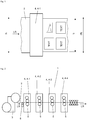
- Fig. 2 shows a web printing machine 1 according to the invention, with which the in Fig. 1 illustrated phenomenon is resolved.
- Web printing machine 1 shown by way of example is essentially a web printing machine 1, as is essentially known from the prior art, and is used for printing on a printing material web 2 guided through web printing machine 1 in a web running direction LR.
- the printing material web 2 is fed to the printing units 4 by means of a feed device 3; roll changers or unwinders are usually used as the feeding device 3, in which the printing material web 2 is unwound from a roll.
- the feed device 3 also comprises elements for laterally aligning the printing material web 2 and / or for building up a defined web tension, such as a feed mechanism.
- the printing material web 2 is fed with the web running direction LR to a plurality of printing units 4 arranged one behind the other as seen in the web running direction LR.
- Each printing unit 4 comprises a cylinder group 5, which in the in Fig. 2 example shown consists of a as a forme cylinder and a transfer cylinder on the top of the web and an impression cylinder on the bottom of the web.
- the configuration of the cylinder group 5 can also deviate from that in FIGS Fig. 2
- the example shown can be configured, for example for double-sided offset printing, for gravure printing or for example with a central cylinder and therefore form and transfer cylinders arranged in a satellite shape, as is known from flexographic printing.
- the printing material web 2 is clamped by each cylinder group 5, since a corresponding pressure must prevail for the transfer of the printing or process ink to the printing material.
- a web offset printing press with a horizontal web guide is shown
- the present invention can also be applied to any other configuration of a web printing press 1, for example a web printing press 1 with a vertical web guide, in which the printing units 4 are arranged one above the other.
- the web printing press 1 further comprises an image control device 6 which comprises a plurality of image regulators 7 arranged next to one another and generally distributed over the web width B.
- These image regulators 7 can either be configured as mechanical image regulators 7 in the form of rotatably mounted rollers, which are brought into contact with the printing material web 2 in the form, so that the printing material web 2 remains.
- the image regulators 7 can alternatively also be configured as nozzles charged with compressed air and thus as image regulator nozzles 7, so that there is no longer any direct mechanical contact between the printing material web 2 and each image regulator 7, since there is between each image regulator 7 and the printing material web 2 builds up an air cushion.
- the image control device 6, seen in the web running direction LR is arranged in front of the cylinder group 5 of the first printing unit 4-1 seen in the web running direction LR, so that the printing material web 2 is already in front of the very first cylinder group 5 and thus in front of the very first cylinder group 5 by means of an image control device 6 lingers and is thereby narrowed in its effective width b.
- a plurality of image control devices 6 in front of the cylinder group 5 of the first printing unit 4-1, in the running direction LR or perpendicular to the curl of the printing material web 2.
- the image control device 6 is arranged in front of the first printing unit 4-1, viewed in the web running direction LR. Although in Fig. 2 not shown, it is also possible to arrange the image control device 6 relatively close to the cylinder group 5 of the first printing unit 4-1 and thus spatially seen already within the contour of the first printing unit 4-1.
- FIG. 3 shows a plan view of the printing material web 2 in the area around the first printing unit 4-1 and shows the effect of the method carried out with the web printing machine 1 according to the invention.
- the Fig. 3 the image control device 6, which is hidden in this view by the printing material web 2 and is therefore shown in broken lines, with the corresponding five image controllers 7, which are shown by way of example and which are seen in the web running direction LR in front of the in Fig. 3 Not shown cylinder group 5 of the first printing unit 4-1 seen in the web running direction LR is arranged.
- the printing material web 2 fed by the feed device 3 with the web width B is held in front of the cylinder group 5 of the first printing unit 4-1 by means of an image control device 6.
- the effective width b projected onto the plane spanned by the printing material web 2 is thus smaller than the original web width B, so that the still unprinted printing material web 2 is narrowed in the plan view and thus in the projected plane.
- the deflection and thus the curling of the printing material web 2 can be adjusted by means of the adjustment of the image regulator 7 of the image control device 6 such that the effective width b in front of the cylinder group 5 of the first printing unit 4-1 is preferably identical to the effective width b after the first printing unit 4 -1, so that the printed images, which are all applied to a printing material web 2 with an identical effective width b by the usually plurality of printing units 4 arranged one behind the other and thus have no register or register deviations of the respective process colors from one another.
- Fig. 4 shows an advantageous embodiment of a web printing press 1, in which the at least one image control device 6 is arranged in addition to the first printing unit 4-1 seen in the web running direction LR and also in front of the cylinder group 5 at least one of the first printing units 4-1 arranged downstream in the web running direction LR .
- FIG. 4 The example shown is an image control device 6 in front of the cylinder group 5 of the first printing unit 4-1 and additionally an image control device 6 in front of the cylinder group 5 of the third printing unit 4-3.
- Fig. 5 shows a schematic view of the image control device 6 in the web running direction LR in an embodiment in which an image control device 6 is arranged on the underside of the printing material web 2 and the printing material web 2 is thus corrugated in the form of a circular arc segment.
- the printing material web 2 in order to reduce the original web width B to an effective width b, the printing material web 2 is deflected in one direction with respect to the plane spanned by the printing material web 2.
- the image control device 6 has, for example, five image regulators 7, the number of image regulators 7 generally not being decisive and, in practice, being able to vary between two and ten, which is essentially dependent on the web width B and the printing material.
- Fig. 6 shows a schematic view in the web running direction LR comparable to Fig. 5 in another embodiment, in which the printing material web 2 is held by an image control device 6 on the top and bottom of the printing material web 2.
- the printing material web 2 is deflected in both directions with respect to the plane spanned by the printing material web 2.
- the upper image control device 6 has, for example, two image regulators 7 and the lower image control device 6 has three image regulators 7, the number of image regulators 7 generally not being decisive and, in practice, being able to vary between two and ten, which essentially depends on the Web width B and the substrate.
Landscapes
- Engineering & Computer Science (AREA)
- Mechanical Engineering (AREA)
- Rotary Presses (AREA)
- Registering, Tensioning, Guiding Webs, And Rollers Therefor (AREA)
Applications Claiming Priority (1)
| Application Number | Priority Date | Filing Date | Title |
|---|---|---|---|
| DE102019101024.1A DE102019101024A1 (de) | 2019-01-16 | 2019-01-16 | Vorrichtung und Verfahren zur Druckbreitenkompensation |
Publications (3)
| Publication Number | Publication Date |
|---|---|
| EP3683060A2 true EP3683060A2 (fr) | 2020-07-22 |
| EP3683060A3 EP3683060A3 (fr) | 2020-07-29 |
| EP3683060B1 EP3683060B1 (fr) | 2021-09-29 |
Family
ID=69159612
Family Applications (1)
| Application Number | Title | Priority Date | Filing Date |
|---|---|---|---|
| EP20151351.2A Active EP3683060B1 (fr) | 2019-01-16 | 2020-01-13 | Dispositif et procédé de compensation de la largeur d'impression |
Country Status (4)
| Country | Link |
|---|---|
| EP (1) | EP3683060B1 (fr) |
| CN (1) | CN111439023B (fr) |
| DE (1) | DE102019101024A1 (fr) |
| ES (1) | ES2893798T3 (fr) |
Cited By (1)
| Publication number | Priority date | Publication date | Assignee | Title |
|---|---|---|---|---|
| DE102021203049A1 (de) | 2021-03-26 | 2022-09-29 | Continental Reifen Deutschland Gmbh | Fahrzeugluftreifen |
Citations (1)
| Publication number | Priority date | Publication date | Assignee | Title |
|---|---|---|---|---|
| DE102004004264C5 (de) | 2004-01-28 | 2011-02-24 | Koenig & Bauer Aktiengesellschaft | Verfahren zur Kompensation einer Querdehnung und/oder einer Längsdehnung eines Bedruckstoffes und Druckmaschine mit mehreren mindestens ein Druckbild auf einem Bedruckstoff erzeugenden Druckwerken |
Family Cites Families (10)
| Publication number | Priority date | Publication date | Assignee | Title |
|---|---|---|---|---|
| DE29501373U1 (de) * | 1995-01-30 | 1995-04-27 | MAN Roland Druckmaschinen AG, 63075 Offenbach | Vorrichtung zur Korrektur des Fan-Out-Effekts an Rollenrotationsdruckmaschinen |
| DE19535632C2 (de) * | 1995-09-25 | 2002-02-28 | Wifag Maschf | Vorrichtung zur Verhinderung von Registerabweichungen beim Bedrucken einer in einer Rotationsdruckmaschine laufenden Bedruckstoffbahn |
| DE59902522D1 (de) * | 1998-04-22 | 2002-10-10 | Wifag Maschf | Registerhaltiger Antrieb eines Druckzylinders oder einer Schnittregisterwalze einer Rotationsdruckmaschine |
| DE10311219A1 (de) * | 2003-03-14 | 2004-09-30 | Werner Kammann Maschinenfabrik Gmbh | Verfahren und Vorrichtung zum Bedrucken einer Bahn |
| JP4276463B2 (ja) * | 2003-04-10 | 2009-06-10 | 東芝機械株式会社 | 輪転印刷機の追い刷り装置および追い刷り方法 |
| DE102008043767A1 (de) * | 2008-11-14 | 2010-06-02 | Koenig & Bauer Aktiengesellschaft | Druckmaschine und Verfahren zur Handhabung einer durch die Druckmaschine geführten Bahn |
| JP2014516823A (ja) * | 2011-04-29 | 2014-07-17 | マンローラント・アーゲー | 回転式オフセット印刷機、及び基材に印刷するための方法 |
| DE102011121319A1 (de) * | 2011-12-16 | 2013-06-20 | Gallus Stanz- Und Druckmaschinen Gmbh | Tiefdruckwerk mit Bahnspannungsausgleich und Verfahren zum Warten eines solchen Tiefdruckwerks |
| DE102015112780A1 (de) * | 2015-08-04 | 2017-02-09 | Manroland Web Systems Gmbh | Fan-Out-Aktoren |
| DE102017215110B4 (de) * | 2017-08-30 | 2020-05-14 | Koenig & Bauer Ag | Vorrichtung zur Kompensation von Fanout |
-
2019
- 2019-01-16 DE DE102019101024.1A patent/DE102019101024A1/de not_active Withdrawn
-
2020
- 2020-01-13 ES ES20151351T patent/ES2893798T3/es active Active
- 2020-01-13 EP EP20151351.2A patent/EP3683060B1/fr active Active
- 2020-01-16 CN CN202010046648.8A patent/CN111439023B/zh active Active
Patent Citations (1)
| Publication number | Priority date | Publication date | Assignee | Title |
|---|---|---|---|---|
| DE102004004264C5 (de) | 2004-01-28 | 2011-02-24 | Koenig & Bauer Aktiengesellschaft | Verfahren zur Kompensation einer Querdehnung und/oder einer Längsdehnung eines Bedruckstoffes und Druckmaschine mit mehreren mindestens ein Druckbild auf einem Bedruckstoff erzeugenden Druckwerken |
Cited By (2)
| Publication number | Priority date | Publication date | Assignee | Title |
|---|---|---|---|---|
| DE102021203049A1 (de) | 2021-03-26 | 2022-09-29 | Continental Reifen Deutschland Gmbh | Fahrzeugluftreifen |
| WO2022199730A1 (fr) | 2021-03-26 | 2022-09-29 | Continental Reifen Deutschland Gmbh | Pneumatique de véhicule |
Also Published As
| Publication number | Publication date |
|---|---|
| CN111439023B (zh) | 2024-03-05 |
| DE102019101024A1 (de) | 2020-07-16 |
| EP3683060B1 (fr) | 2021-09-29 |
| CN111439023A (zh) | 2020-07-24 |
| ES2893798T3 (es) | 2022-02-10 |
| EP3683060A3 (fr) | 2020-07-29 |
Similar Documents
| Publication | Publication Date | Title |
|---|---|---|
| DE102007049670B4 (de) | Verfahren zur Registerkorrektur bei einer Bearbeitungsmaschine sowie Bearbeitungsmaschine | |
| DE10033467A1 (de) | Falzapparatanordnung in einer Rollenrotations-Zeitungsdruckmaschine | |
| EP1924435B1 (fr) | Presse et procede pour corriger le reperage | |
| DE4327646C5 (de) | Breiten-Einstellverfahren für eine Papierbahn sowie damit ausgerüstete lithographische Rotationspresse | |
| DE10110122B4 (de) | Vorrichtung und Verfahren zur Steuerung der Bahnspannung | |
| DE102009056293B4 (de) | Vorrichtung und Verfahren zum Regeln der Spannung einer Substratbahn | |
| DE4224236A1 (de) | Offset-rotationspresse fuer farbdrucksystem | |
| EP1347878B1 (fr) | Procede pour reguler un reperage circonferentiel dans une rotative a bobine | |
| EP3683060B1 (fr) | Dispositif et procédé de compensation de la largeur d'impression | |
| WO2006021104A1 (fr) | Dispositif de pliage longitudinal comprenant des cones plieurs de differentes largeurs | |
| EP1759844B1 (fr) | Procédé pour corriger l'impression | |
| DE102015121398A1 (de) | Formatvariable Rollendruckmaschine | |
| EP2223806A1 (fr) | Dispositif et procédé d'écartement de bandes se déroulant dans le sens transversal par rapport à l'axe longitudinal d'une presse d'impression rotative | |
| DE10232109A1 (de) | Offsetdruckwerk und Offsetdruckverfahren | |
| DE202019100234U1 (de) | Vorrichtung zur Druckbreitenkompensation | |
| DE102006052865B4 (de) | Rollenrotationsdruckmaschine | |
| DE19545113A1 (de) | Digitale Druckmaschine und Verfahren zum Bogentransport dafür | |
| EP0765746B1 (fr) | Machine d'impression et procédé d'alimentation en feuilles sous plusieurs cylindres d'impression | |
| EP1712355B2 (fr) | Unité d'impression d'une machine rotative d'impression | |
| DE102006018462A1 (de) | Verfahren zum Steuern und/oder Regeln eines Registers in einer Druckmaschine | |
| DE102012013002A1 (de) | Rollendruckmaschine | |
| DE202008012699U1 (de) | Vorrichtung zur Seitenregistrierung von Teilbahnen | |
| EP1712354B1 (fr) | Unité d'impression d'une presse rotative | |
| DE10354432A1 (de) | Verfahren zum Steuern der Zufuhr einer Bedruckstoffbahn in eine Druckmaschine | |
| DE102023132866A1 (de) | Verfahren zum Inline-Regeln eines Druckparameters |
Legal Events
| Date | Code | Title | Description |
|---|---|---|---|
| PUAI | Public reference made under article 153(3) epc to a published international application that has entered the european phase |
Free format text: ORIGINAL CODE: 0009012 |
|
| STAA | Information on the status of an ep patent application or granted ep patent |
Free format text: STATUS: THE APPLICATION HAS BEEN PUBLISHED |
|
| PUAL | Search report despatched |
Free format text: ORIGINAL CODE: 0009013 |
|
| AK | Designated contracting states |
Kind code of ref document: A2 Designated state(s): AL AT BE BG CH CY CZ DE DK EE ES FI FR GB GR HR HU IE IS IT LI LT LU LV MC MK MT NL NO PL PT RO RS SE SI SK SM TR |
|
| AX | Request for extension of the european patent |
Extension state: BA ME |
|
| AK | Designated contracting states |
Kind code of ref document: A3 Designated state(s): AL AT BE BG CH CY CZ DE DK EE ES FI FR GB GR HR HU IE IS IT LI LT LU LV MC MK MT NL NO PL PT RO RS SE SI SK SM TR |
|
| AX | Request for extension of the european patent |
Extension state: BA ME |
|
| RIC1 | Information provided on ipc code assigned before grant |
Ipc: B41F 23/00 20060101AFI20200624BHEP Ipc: B41F 13/02 20060101ALI20200624BHEP Ipc: B65H 23/02 20060101ALI20200624BHEP Ipc: B65H 23/025 20060101ALI20200624BHEP |
|
| STAA | Information on the status of an ep patent application or granted ep patent |
Free format text: STATUS: REQUEST FOR EXAMINATION WAS MADE |
|
| 17P | Request for examination filed |
Effective date: 20210126 |
|
| RBV | Designated contracting states (corrected) |
Designated state(s): AL AT BE BG CH CY CZ DE DK EE ES FI FR GB GR HR HU IE IS IT LI LT LU LV MC MK MT NL NO PL PT RO RS SE SI SK SM TR |
|
| GRAP | Despatch of communication of intention to grant a patent |
Free format text: ORIGINAL CODE: EPIDOSNIGR1 |
|
| STAA | Information on the status of an ep patent application or granted ep patent |
Free format text: STATUS: GRANT OF PATENT IS INTENDED |
|
| INTG | Intention to grant announced |
Effective date: 20210720 |
|
| GRAS | Grant fee paid |
Free format text: ORIGINAL CODE: EPIDOSNIGR3 |
|
| GRAA | (expected) grant |
Free format text: ORIGINAL CODE: 0009210 |
|
| STAA | Information on the status of an ep patent application or granted ep patent |
Free format text: STATUS: THE PATENT HAS BEEN GRANTED |
|
| AK | Designated contracting states |
Kind code of ref document: B1 Designated state(s): AL AT BE BG CH CY CZ DE DK EE ES FI FR GB GR HR HU IE IS IT LI LT LU LV MC MK MT NL NO PL PT RO RS SE SI SK SM TR |
|
| REG | Reference to a national code |
Ref country code: GB Ref legal event code: FG4D Free format text: NOT ENGLISH |
|
| REG | Reference to a national code |
Ref country code: DE Ref legal event code: R096 Ref document number: 502020000209 Country of ref document: DE |
|
| REG | Reference to a national code |
Ref country code: CH Ref legal event code: EP Ref country code: AT Ref legal event code: REF Ref document number: 1433874 Country of ref document: AT Kind code of ref document: T Effective date: 20211015 |
|
| REG | Reference to a national code |
Ref country code: IE Ref legal event code: FG4D Free format text: LANGUAGE OF EP DOCUMENT: GERMAN |
|
| REG | Reference to a national code |
Ref country code: NL Ref legal event code: FP |
|
| REG | Reference to a national code |
Ref country code: LT Ref legal event code: MG9D |
|
| PG25 | Lapsed in a contracting state [announced via postgrant information from national office to epo] |
Ref country code: RS Free format text: LAPSE BECAUSE OF FAILURE TO SUBMIT A TRANSLATION OF THE DESCRIPTION OR TO PAY THE FEE WITHIN THE PRESCRIBED TIME-LIMIT Effective date: 20210929 Ref country code: SE Free format text: LAPSE BECAUSE OF FAILURE TO SUBMIT A TRANSLATION OF THE DESCRIPTION OR TO PAY THE FEE WITHIN THE PRESCRIBED TIME-LIMIT Effective date: 20210929 Ref country code: FI Free format text: LAPSE BECAUSE OF FAILURE TO SUBMIT A TRANSLATION OF THE DESCRIPTION OR TO PAY THE FEE WITHIN THE PRESCRIBED TIME-LIMIT Effective date: 20210929 Ref country code: HR Free format text: LAPSE BECAUSE OF FAILURE TO SUBMIT A TRANSLATION OF THE DESCRIPTION OR TO PAY THE FEE WITHIN THE PRESCRIBED TIME-LIMIT Effective date: 20210929 Ref country code: NO Free format text: LAPSE BECAUSE OF FAILURE TO SUBMIT A TRANSLATION OF THE DESCRIPTION OR TO PAY THE FEE WITHIN THE PRESCRIBED TIME-LIMIT Effective date: 20211229 Ref country code: LT Free format text: LAPSE BECAUSE OF FAILURE TO SUBMIT A TRANSLATION OF THE DESCRIPTION OR TO PAY THE FEE WITHIN THE PRESCRIBED TIME-LIMIT Effective date: 20210929 Ref country code: BG Free format text: LAPSE BECAUSE OF FAILURE TO SUBMIT A TRANSLATION OF THE DESCRIPTION OR TO PAY THE FEE WITHIN THE PRESCRIBED TIME-LIMIT Effective date: 20211229 |
|
| REG | Reference to a national code |
Ref country code: ES Ref legal event code: FG2A Ref document number: 2893798 Country of ref document: ES Kind code of ref document: T3 Effective date: 20220210 |
|
| PG25 | Lapsed in a contracting state [announced via postgrant information from national office to epo] |
Ref country code: LV Free format text: LAPSE BECAUSE OF FAILURE TO SUBMIT A TRANSLATION OF THE DESCRIPTION OR TO PAY THE FEE WITHIN THE PRESCRIBED TIME-LIMIT Effective date: 20210929 Ref country code: GR Free format text: LAPSE BECAUSE OF FAILURE TO SUBMIT A TRANSLATION OF THE DESCRIPTION OR TO PAY THE FEE WITHIN THE PRESCRIBED TIME-LIMIT Effective date: 20211230 |
|
| PG25 | Lapsed in a contracting state [announced via postgrant information from national office to epo] |
Ref country code: IS Free format text: LAPSE BECAUSE OF FAILURE TO SUBMIT A TRANSLATION OF THE DESCRIPTION OR TO PAY THE FEE WITHIN THE PRESCRIBED TIME-LIMIT Effective date: 20220129 Ref country code: SK Free format text: LAPSE BECAUSE OF FAILURE TO SUBMIT A TRANSLATION OF THE DESCRIPTION OR TO PAY THE FEE WITHIN THE PRESCRIBED TIME-LIMIT Effective date: 20210929 Ref country code: RO Free format text: LAPSE BECAUSE OF FAILURE TO SUBMIT A TRANSLATION OF THE DESCRIPTION OR TO PAY THE FEE WITHIN THE PRESCRIBED TIME-LIMIT Effective date: 20210929 Ref country code: PT Free format text: LAPSE BECAUSE OF FAILURE TO SUBMIT A TRANSLATION OF THE DESCRIPTION OR TO PAY THE FEE WITHIN THE PRESCRIBED TIME-LIMIT Effective date: 20220131 Ref country code: PL Free format text: LAPSE BECAUSE OF FAILURE TO SUBMIT A TRANSLATION OF THE DESCRIPTION OR TO PAY THE FEE WITHIN THE PRESCRIBED TIME-LIMIT Effective date: 20210929 Ref country code: EE Free format text: LAPSE BECAUSE OF FAILURE TO SUBMIT A TRANSLATION OF THE DESCRIPTION OR TO PAY THE FEE WITHIN THE PRESCRIBED TIME-LIMIT Effective date: 20210929 Ref country code: CZ Free format text: LAPSE BECAUSE OF FAILURE TO SUBMIT A TRANSLATION OF THE DESCRIPTION OR TO PAY THE FEE WITHIN THE PRESCRIBED TIME-LIMIT Effective date: 20210929 Ref country code: AL Free format text: LAPSE BECAUSE OF FAILURE TO SUBMIT A TRANSLATION OF THE DESCRIPTION OR TO PAY THE FEE WITHIN THE PRESCRIBED TIME-LIMIT Effective date: 20210929 |
|
| REG | Reference to a national code |
Ref country code: DE Ref legal event code: R097 Ref document number: 502020000209 Country of ref document: DE |
|
| PG25 | Lapsed in a contracting state [announced via postgrant information from national office to epo] |
Ref country code: DK Free format text: LAPSE BECAUSE OF FAILURE TO SUBMIT A TRANSLATION OF THE DESCRIPTION OR TO PAY THE FEE WITHIN THE PRESCRIBED TIME-LIMIT Effective date: 20210929 |
|
| PLBE | No opposition filed within time limit |
Free format text: ORIGINAL CODE: 0009261 |
|
| STAA | Information on the status of an ep patent application or granted ep patent |
Free format text: STATUS: NO OPPOSITION FILED WITHIN TIME LIMIT |
|
| PG25 | Lapsed in a contracting state [announced via postgrant information from national office to epo] |
Ref country code: MC Free format text: LAPSE BECAUSE OF FAILURE TO SUBMIT A TRANSLATION OF THE DESCRIPTION OR TO PAY THE FEE WITHIN THE PRESCRIBED TIME-LIMIT Effective date: 20210929 |
|
| 26N | No opposition filed |
Effective date: 20220630 |
|
| REG | Reference to a national code |
Ref country code: BE Ref legal event code: MM Effective date: 20220131 |
|
| PG25 | Lapsed in a contracting state [announced via postgrant information from national office to epo] |
Ref country code: LU Free format text: LAPSE BECAUSE OF NON-PAYMENT OF DUE FEES Effective date: 20220113 |
|
| PG25 | Lapsed in a contracting state [announced via postgrant information from national office to epo] |
Ref country code: SI Free format text: LAPSE BECAUSE OF FAILURE TO SUBMIT A TRANSLATION OF THE DESCRIPTION OR TO PAY THE FEE WITHIN THE PRESCRIBED TIME-LIMIT Effective date: 20210929 Ref country code: BE Free format text: LAPSE BECAUSE OF NON-PAYMENT OF DUE FEES Effective date: 20220131 |
|
| PG25 | Lapsed in a contracting state [announced via postgrant information from national office to epo] |
Ref country code: IE Free format text: LAPSE BECAUSE OF NON-PAYMENT OF DUE FEES Effective date: 20220113 |
|
| PG25 | Lapsed in a contracting state [announced via postgrant information from national office to epo] |
Ref country code: SM Free format text: LAPSE BECAUSE OF FAILURE TO SUBMIT A TRANSLATION OF THE DESCRIPTION OR TO PAY THE FEE WITHIN THE PRESCRIBED TIME-LIMIT Effective date: 20210929 Ref country code: MK Free format text: LAPSE BECAUSE OF FAILURE TO SUBMIT A TRANSLATION OF THE DESCRIPTION OR TO PAY THE FEE WITHIN THE PRESCRIBED TIME-LIMIT Effective date: 20210929 Ref country code: CY Free format text: LAPSE BECAUSE OF FAILURE TO SUBMIT A TRANSLATION OF THE DESCRIPTION OR TO PAY THE FEE WITHIN THE PRESCRIBED TIME-LIMIT Effective date: 20210929 |
|
| PG25 | Lapsed in a contracting state [announced via postgrant information from national office to epo] |
Ref country code: HU Free format text: LAPSE BECAUSE OF FAILURE TO SUBMIT A TRANSLATION OF THE DESCRIPTION OR TO PAY THE FEE WITHIN THE PRESCRIBED TIME-LIMIT; INVALID AB INITIO Effective date: 20200113 |
|
| GBPC | Gb: european patent ceased through non-payment of renewal fee |
Effective date: 20240113 |
|
| PG25 | Lapsed in a contracting state [announced via postgrant information from national office to epo] |
Ref country code: MT Free format text: LAPSE BECAUSE OF FAILURE TO SUBMIT A TRANSLATION OF THE DESCRIPTION OR TO PAY THE FEE WITHIN THE PRESCRIBED TIME-LIMIT Effective date: 20210929 |
|
| PG25 | Lapsed in a contracting state [announced via postgrant information from national office to epo] |
Ref country code: GB Free format text: LAPSE BECAUSE OF NON-PAYMENT OF DUE FEES Effective date: 20240113 |
|
| PG25 | Lapsed in a contracting state [announced via postgrant information from national office to epo] |
Ref country code: GB Free format text: LAPSE BECAUSE OF NON-PAYMENT OF DUE FEES Effective date: 20240113 |
|
| PGFP | Annual fee paid to national office [announced via postgrant information from national office to epo] |
Ref country code: AT Payment date: 20250417 Year of fee payment: 5 |
|
| PG25 | Lapsed in a contracting state [announced via postgrant information from national office to epo] |
Ref country code: TR Free format text: LAPSE BECAUSE OF FAILURE TO SUBMIT A TRANSLATION OF THE DESCRIPTION OR TO PAY THE FEE WITHIN THE PRESCRIBED TIME-LIMIT Effective date: 20210929 |
|
| REG | Reference to a national code |
Ref country code: CH Ref legal event code: U11 Free format text: ST27 STATUS EVENT CODE: U-0-0-U10-U11 (AS PROVIDED BY THE NATIONAL OFFICE) Effective date: 20260201 |
|
| PGFP | Annual fee paid to national office [announced via postgrant information from national office to epo] |
Ref country code: NL Payment date: 20260121 Year of fee payment: 7 |
|
| REG | Reference to a national code |
Ref country code: AT Ref legal event code: MM01 Ref document number: 1433874 Country of ref document: AT Kind code of ref document: T Effective date: 20250113 |
|
| PGFP | Annual fee paid to national office [announced via postgrant information from national office to epo] |
Ref country code: ES Payment date: 20260227 Year of fee payment: 7 |
|
| PGFP | Annual fee paid to national office [announced via postgrant information from national office to epo] |
Ref country code: DE Payment date: 20260121 Year of fee payment: 7 |
|
| PG25 | Lapsed in a contracting state [announced via postgrant information from national office to epo] |
Ref country code: AT Free format text: LAPSE BECAUSE OF NON-PAYMENT OF DUE FEES Effective date: 20250113 |
|
| PGFP | Annual fee paid to national office [announced via postgrant information from national office to epo] |
Ref country code: IT Payment date: 20260126 Year of fee payment: 7 |
|
| PGFP | Annual fee paid to national office [announced via postgrant information from national office to epo] |
Ref country code: FR Payment date: 20260123 Year of fee payment: 7 |
|
| PGFP | Annual fee paid to national office [announced via postgrant information from national office to epo] |
Ref country code: CH Payment date: 20260201 Year of fee payment: 7 |