EP3683143B1 - Systèmes de commande de vol modaux de poutre de queue pour hélicoptères composés - Google Patents
Systèmes de commande de vol modaux de poutre de queue pour hélicoptères composés Download PDFInfo
- Publication number
- EP3683143B1 EP3683143B1 EP20150763.9A EP20150763A EP3683143B1 EP 3683143 B1 EP3683143 B1 EP 3683143B1 EP 20150763 A EP20150763 A EP 20150763A EP 3683143 B1 EP3683143 B1 EP 3683143B1
- Authority
- EP
- European Patent Office
- Prior art keywords
- tailboom
- modal
- torque
- pusher propeller
- control system
- Prior art date
- Legal status (The legal status is an assumption and is not a legal conclusion. Google has not performed a legal analysis and makes no representation as to the accuracy of the status listed.)
- Active
Links
Images


Classifications
-
- B—PERFORMING OPERATIONS; TRANSPORTING
- B64—AIRCRAFT; AVIATION; COSMONAUTICS
- B64C—AEROPLANES; HELICOPTERS
- B64C27/00—Rotorcraft; Rotors peculiar thereto
- B64C27/82—Rotorcraft; Rotors peculiar thereto characterised by the provision of an auxiliary rotor or fluid-jet device for counter-balancing lifting rotor torque or changing direction of rotorcraft
-
- B—PERFORMING OPERATIONS; TRANSPORTING
- B64—AIRCRAFT; AVIATION; COSMONAUTICS
- B64C—AEROPLANES; HELICOPTERS
- B64C27/00—Rotorcraft; Rotors peculiar thereto
- B64C27/22—Compound rotorcraft, i.e. aircraft using in flight the features of both aeroplane and rotorcraft
- B64C27/26—Compound rotorcraft, i.e. aircraft using in flight the features of both aeroplane and rotorcraft characterised by provision of fixed wings
-
- B—PERFORMING OPERATIONS; TRANSPORTING
- B64—AIRCRAFT; AVIATION; COSMONAUTICS
- B64C—AEROPLANES; HELICOPTERS
- B64C27/00—Rotorcraft; Rotors peculiar thereto
- B64C27/82—Rotorcraft; Rotors peculiar thereto characterised by the provision of an auxiliary rotor or fluid-jet device for counter-balancing lifting rotor torque or changing direction of rotorcraft
- B64C2027/8227—Rotorcraft; Rotors peculiar thereto characterised by the provision of an auxiliary rotor or fluid-jet device for counter-balancing lifting rotor torque or changing direction of rotorcraft comprising more than one rotor
-
- B—PERFORMING OPERATIONS; TRANSPORTING
- B64—AIRCRAFT; AVIATION; COSMONAUTICS
- B64C—AEROPLANES; HELICOPTERS
- B64C27/00—Rotorcraft; Rotors peculiar thereto
- B64C27/82—Rotorcraft; Rotors peculiar thereto characterised by the provision of an auxiliary rotor or fluid-jet device for counter-balancing lifting rotor torque or changing direction of rotorcraft
- B64C2027/8236—Rotorcraft; Rotors peculiar thereto characterised by the provision of an auxiliary rotor or fluid-jet device for counter-balancing lifting rotor torque or changing direction of rotorcraft including pusher propellers
Definitions
- the present disclosure relates, in general, to tailbooms of compound helicopters and, in particular, to tailboom flight control systems operable in a variety of modes and having a pusher propeller and/or other flight control elements positioned forward of an anti-torque system.
- the cyclic control of a conventional helicopter is used to cyclically vary the attack angles of the rotor blades of a main rotor to change the helicopter's direction of movement.
- Conventional helicopters have a limited top speed due to the problem of retreating blade stall, in which the rotor blade with the smaller resultant relative wind exceeds the critical angle of attack.
- Attempts have also been made to overcome retreating blade stall by utilizing an "advancing blade concept,” in which rotor blades advance on both sides of the rotorcraft during flight, typically by employing two counter rotating rotors. It has been found, however, that advancing blade concept rotorcraft are particularly susceptible to structural vibration, contributing to crew fatigue, increased operating costs and structural instability.
- VTOL vertical takeoff and landing
- Current compound helicopters position the pusher propeller aft of the tail rotor, thereby reducing the lever arm on which anti-torque thrust may act and requiring the tail rotor to be placed outboard of the pusher propeller rotor disk.
- Current compound helicopters may also lack multi-modal flight capabilities and/or fail to adequately protect the pusher propeller.
- US4514142 discloses a power management system for an advanced helicopter having both lift and thrust propulsion units and at least one power plant which comprises a signal generator for generating a first signal which is proportional to the power available from the power plant, a power use gauge connected to the lift propulsion unit which has an output that varies according to the amount of power used by that propulsion unit and a circuit which is connected to the power use gauge and which receives the first signal for generating a second signal which is proportional to the amount of power remaining.
- the circuit is either used to power an indicator which indicates to the pilot the amount of power remaining for the thrust propulsion unit, or can be connected directly to a limit actuator for limiting the amount of power the pilot can apply to the thrust propulsion unit.
- EP3254962 discloses an electric distributed propulsion system for anti-torque modules for a helicopter and methods of use comprising: two or more generators connected to a main gearbox transmission; at least a first and a second plurality of variable speed motors connected to one or more fixed pitch blades to provide anti-torque thrust connected to the two or more generators, and at least a first and a second yaw control computer independently connected to each of the at least first and second plurality of variable speed motors, wherein each of the first and second yaw control computer serves as a primary and a backup yaw control computer to provide redundant control to both the first and second plurality of variable speed motors.
- the present disclosure is directed to a modal tailboom flight control system for a compound helicopter.
- the modal tailboom flight control system is operable in a plurality of modes including a forward thrust mode and an anti-torque mode.
- the modal tailboom flight control system includes a tailboom, a drivetrain extending through the tailboom, an anti-torque system coupled to the drivetrain and rotatable to generate anti-torque thrust for the compound helicopter in the anti-torque mode and a pusher propeller coupled to the drivetrain and rotatable to generate forward thrust for the compound helicopter in the forward thrust mode.
- the pusher propeller is positioned forward of the anti-torque system.
- the rotational speed of the pusher propeller may increase relative to the rotational speed of the anti-torque system in the forward thrust mode and the rotational speed of the pusher propeller may decrease relative to the rotational speed of the anti-torque system in the anti-torque mode.
- the pusher propeller and the anti-torque system may each include variable pitch rotor blades.
- the variable pitch rotor blades of the pusher propeller may be pitched to increase the forward thrust generated by the pusher propeller in the forward thrust mode and the variable pitch rotor blades of the anti-torque system may be pitched to increase the anti-torque thrust generated by the anti-torque system in the anti-torque mode.
- the compound helicopter may be operable in a forward flight mode and a vertical takeoff and landing mode.
- the modal tailboom flight control system may be in the forward thrust mode when the compound helicopter is in the forward flight mode and in the anti-torque mode when the compound helicopter is in the vertical takeoff and landing mode.
- the tailboom may include a tapered aft end, and the anti-torque system may be rotatably coupled to the tapered aft end of the tailboom.
- the anti-torque system may include a tail rotor.
- the tail rotor may include a tail rotor hub assembly offset by a distance D from the centerline of the compound helicopter, the pusher propeller has a radius R and the distance D may be less than the radius R. In other embodiments, the distance D may be less than half of the radius R.
- the anti-torque system may include a cross-flow fan.
- the pusher propeller may include a rotor hub fairing substantially flush with the tailboom.
- the modal tailboom flight control system may include a flight stabilizer positioned forward of the pusher propeller.
- the flight stabilizer may partially obstruct a forward side of the pusher propeller to protect the pusher propeller from debris during flight.
- the flight stabilizer may include a horizontal stabilizer.
- the pusher propeller has a diameter D
- the horizontal stabilizer has a width W and the diameter D may be less than the width W.
- the anti-torque system may include a tail rotor hub assembly offset by a distance D from the centerline of the compound helicopter, the horizontal stabilizer has a width W and the distance D may be less than half of the width W.
- the flight stabilizer may include vertical fins coupled to outboard ends of the horizontal stabilizer.
- the present disclosure is directed to a compound helicopter including a fuselage and a modal tailboom flight control system coupled to the fuselage and operable in a plurality of modes including a forward thrust mode and an anti-torque mode.
- the modal tailboom flight control system includes a tailboom, a drivetrain extending through the tailboom, an anti-torque system coupled to the drivetrain and rotatable to generate anti-torque thrust in the anti-torque mode and a pusher propeller coupled to the drivetrain and rotatable to generate forward thrust in the forward thrust mode.
- the pusher propeller is positioned forward of the anti-torque system.
- the drivetrain may include a pusher propeller clutch and an anti-torque system clutch, and the rotational speeds of the pusher propeller and the anti-torque system may be independently controllable using the pusher propeller clutch and the anti-torque system clutch.
- the drivetrain may include an extension driveshaft, aft of the pusher propeller, to transmit rotational energy to the anti-torque system.
- the compound helicopter may include first and second wings protruding from the sides of the fuselage.
- the modal tailboom flight control system may include a flight stabilizer positioned forward of the pusher propeller.
- the flight stabilizer has a width W, the first and second wings form a wingspan Z and the width W is less than the wingspan Z.
- the mode of the modal tailboom flight control system may be switchable based on pilot input.
- the devices, members, apparatuses, and the like described herein may be positioned in any desired orientation.
- the use of terms such as “above,” “below,” “upper,” “lower” or other like terms to describe a spatial relationship between various components or to describe the spatial orientation of aspects of such components should be understood to describe a relative relationship between the components or a spatial orientation of aspects of such components, respectively, as the devices described herein may be oriented in any desired direction.
- the term “coupled” may include direct or indirect coupling by any means, including by mere contact or by moving and/or non-moving mechanical connections.
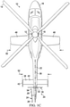
- a compound helicopter is schematically illustrated and generally designated 10.
- the primary propulsion assembly of compound helicopter 10 is a main rotor assembly 12.
- Main rotor assembly 12 includes a plurality of rotor blades 14 extending radially outward from a main rotor hub 16.
- Main rotor assembly 12 is coupled to a fuselage 18.
- Main rotor hub 16 is rotatable relative to fuselage 18.
- the pitch of rotor blades 14 can be collectively and/or cyclically manipulated to selectively control direction, thrust and lift of compound helicopter 10.
- a retractable landing gear system provides ground support for compound helicopter 10.
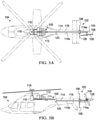
- a modal tailboom flight control system 20 includes a tailboom 22 coupled to fuselage 18 and extending from fuselage 18 in the aft direction.
- An anti-torque system 24 includes a tail rotor 26 that is rotatably coupled to the aft end of tailboom 22.
- Anti-torque system 24 controls the yaw of compound helicopter 10 by counteracting the torque exerted on fuselage 18 by main rotor assembly 12. While tail rotor 26 is illustrated as including four tail rotor blades 28, tail rotor 26 may have any number of tail rotor blades.
- the magnitude of anti-torque thrust generated by tail rotor 26 may be varied in a variety of ways.
- tail rotor blades 28 may be variable pitch tail rotor blades whose pitch is changeable by a pitch change mechanism.
- tail rotor blades 28 may be fixed pitch tail rotor blades and tail rotor 26 may be clutchable and/or have a variable rotational speed.
- a translational thrust system 30 including a pusher propeller 32 that propels compound helicopter 10 in a forward direction.
- compound helicopter 10 may be capable of high forward airspeed. By propelling compound helicopter 10 in the forward direction, pusher propeller 32 may also reduce the drag burden on main rotor assembly 12.
- Pusher propeller 32 may be a variable pitch pusher propeller, variable speed pusher propeller and/or clutchable pusher propeller.
- Pusher propeller 32 is positioned forward of a forward edge of tail rotor 26, depicted as tip 34, such that the rotor disks of tail rotor 26 and pusher propeller 32 do not interfere with each other.
- the rotor disks of tail rotor 26 and pusher propeller 32 may overlap and the rotational speeds of tail rotor 26 and pusher propeller 32 may be synchronized to prevent the rotor blades of pusher propeller 32 from contacting tail rotor blades 28.
- Tail rotor 26 may be positioned at or near centerline 36 of compound helicopter 10 and in the slipstream of pusher propeller 32. Positioning tail rotor 26 on the aft-most section of tailboom 22 also maximizes the lever arm and moment exerted on fuselage 18 to provide more efficient anti-torque thrust for compound helicopter 10.
- a forwardpositioned pusher propeller 32 allows compound helicopter 10 to achieve high forward airspeed while maintaining a small footprint.
- compound helicopter 10 may have a footprint size of equal to or less than 40 feet wide by 40 feet long while achieving forward airspeeds upward of 180 knots, as compared to conventional helicopters that are larger and capable of forward airspeeds of only 125 to 150 knots.
- a flight stabilizer 38 is coupled to tailboom 22 and positioned forward of pusher propeller 32.
- Pusher propeller 32 is thus interposed between tail rotor 26 and flight stabilizer 38.
- Flight stabilizer 38 provides orientational stability for compound helicopter 10 during forward flight. By positioning flight stabilizer 38 in front of pusher propeller 32 and tail rotor 26, flight stabilizer 38 at least partially obstructs a forward side of pusher propeller 32 to protect pusher propeller 32 and tail rotor 26 during flight.
- Flight stabilizer 38 includes a horizontal stabilizer 40 for pitch stability and vertical fins 42 for yaw stability during forward flight. Vertical fins 42 are coupled to the outboard ends of horizontal stabilizer 40.
- Flight stabilizer 38 may also include a central vertical fin 44 on the underside of tailboom 22 to provide additional yaw stability and protection of pusher propeller 32 and tail rotor 26 from ground strike.
- horizontal stabilizer 40 may include one or more movable control surfaces such as elevators for additional pitch control and vertical fins 42 may include one or more movable control surfaces such as rudders for additional yaw control.
- tailboom 22 may not include a flight stabilizer and the forward side of pusher propeller 32 may be unobstructed.
- Compound helicopter 10 also includes wings 46, 48 protruding from the sides of fuselage 18. Wings 46, 48 produce lift while compound helicopter 10 is in forward flight, thereby partially offloading the lift required of main rotor assembly 12. The lift provided by wings 46, 48 may help to offset the reduced lift capacity of main rotor assembly 12 at high forward airspeeds. Wings 46, 48 may be structurally separate wings or may form part of a unitary wing that traverses fuselage 18. As best seen in figure 1C , wings 46, 48 form a wingspan 50 that is wider than width 52 of flight stabilizer 38. The ratio of wingspan 50 to width 52 may vary depending on the embodiment and include ratios such as 1.1:1, 1.25:1, 1.5:1, 1.8:1, 2:1, 2.5:1, 3:1 as well as other ratios.
- tail rotor 26 and pusher propeller 32 are independently controllable to allow modal tailboom flight control system 20 to operate in a variety of modes including a forward thrust mode and an anti-torque mode.
- anti-torque mode the rotational speed of pusher propeller 32 decreases and the rotational speed of tail rotor 26 increases to generate anti-torque thrust for compound helicopter 10.
- forward thrust mode the rotational speed of pusher propeller 32 increases and the rotational speed of tail rotor 26 decreases to generate forward thrust for compound helicopter 10.
- tail rotor 26 and pusher propeller 32 may instead of relying on rotational speed, tail rotor 26 and pusher propeller 32 may instead have variable pitch blades to alter the anti-torque thrust and forward thrust, respectively.
- the mode of modal tailboom flight control system 20 may be responsive to the mode of compound helicopter 10.
- compound helicopter 10 may be operable in a forward flight mode and a vertical takeoff and landing (VTOL) mode.
- modal tailboom flight control system 20 may be in forward thrust mode when compound helicopter 10 is in forward flight mode.
- modal tailboom flight control system 20 may be in anti-torque mode when compound helicopter 10 is in VTOL mode, including during hover operations.
- the modality of modal tailboom flight control system 20 allows additional anti-torque thrust to be generated by tail rotor 26 in takeoff, landing and hover operations and additional forward thrust to be generated by pusher propeller 32 in forward flight.
- Modal tailboom flight control system 20 may be switchable between forward thrust mode and anti-torque mode based on pilot input, such as cyclic control, collective control or other manual input.
- compound helicopter 10 may switch between forward thrust mode and anti-torque mode based on sensory input from sensors in compound helicopter 10.
- modal tailboom flight control system 20 may switch to forward thrust mode based on one or more airspeed sensors detecting if or when compound helicopter 10 exceeds a threshold forward airspeed.
- modal tailboom flight control system 20 may switch to anti-torque mode based on a yaw rate sensor.
- Modal tailboom flight control system 20 is not restricted to being in either forward thrust mode or anti-torque mode at any given time, as modal tailboom flight control system 20 may be in neither or both of these modes at the same time. For example, if yaw or anti-torque control is required during forward flight, modal tailboom flight control system 20 may be in both forward thrust mode and anti-torque mode at the same time even though compound helicopter 10 is in forward flight mode. In such a dual modality scenario, both tail rotor 26 and pusher propeller 32 may have an increased rotational speed, or pitch angle, to generate both anti-torque thrust and forward thrust.
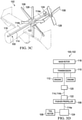
- Tailboom 22 has a tapered aft end 54 to which tail rotor 26 is rotatably coupled.
- tail rotor 26 is positionable at or near centerline 36 of compound helicopter 10.
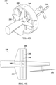
- tail rotor 26 is offset from centerline 36 by a distance 56, which is less than radius 58 of pusher propeller 32.
- offset distance 56 may be less than half of radius 58 of pusher propeller 32. Indeed, offset distance 56 may be less than radius 58 by any ratio.
- offset distance 56 may be 90 percent, 75 percent, 33 percent, 25 percent, 10 percent or 1 percent of radius 58 of pusher propeller 32. Offset distance 56 is also less than half of width 52 of flight stabilizer 38. Offset distance 56 may be less than width 52 by any ratio. For example, offset distance 56 may be 40 percent, 30 percent, 20 percent, 10 percent, 5 percent or 1 percent of width 52 of flight stabilizer 38.
- the rotor hub of pusher propeller 32 is surrounded by a rotor hub fairing 60 that is substantially flush with skin 62 of tailboom 22 to enhance the aerodynamic properties of compound helicopter 10.
- Diameter 64 of pusher propeller 32 is less than width 52 of flight stabilizer 38. Diameter 64 may be less than width 52 by any ratio. For example, diameter 64 may be 90 percent, 75 percent, 33 percent, 25 percent, 10 percent or 5 percent of width 52 of flight stabilizer 38.
- tail rotor 26 is illustrated as being on the port side of compound helicopter 10, in other embodiments tail rotor 26 may be on the starboard side of compound helicopter 10.
- drivetrain 100 of modal tailboom flight control system 102 is schematically illustrated for compound helicopter 104.
- Drivetrain 100 provides rotational energy to both pusher propeller 106 and tail rotor 108.
- Drivetrain 100 includes a transmission 110 that transfers rotational energy from engines 112 to driveshaft 114.
- Driveshaft 114 extends through tailboom 116.
- Both pusher propeller 106 and tail rotor 108 are coupled to driveshaft 114 of drivetrain 100.
- drivetrain 100 may maintain a fixed drivetrain ratio between main rotor assembly 118, pusher propeller 106 and tail rotor 108, although a variable drivetrain ratio may also be implemented between these elements in other embodiments.
- Driveshaft 114 may be formed from two or more driveshaft segments including one or more intermediate gearboxes 120. Intermediate gearbox 120 may change the gear ratio between transmission 110 and pusher propeller 106, as well as lower the elevation of driveshaft 114 as it extends in the aft direction.
- Driveshaft 114 includes an extension driveshaft 114a aft of pusher propeller 106 to transmit rotational energy to tail rotor 108.
- extension driveshaft 114a and an intermediate driveshaft segment 114b may integrally form a single driveshaft that extends through the rotor hub of pusher propeller 106.
- two substantially parallel driveshafts may extend through tailboom 116, each providing rotational energy to a respective one of pusher propeller 106 or tail rotor 108.
- the thrusts emitted by pusher propeller 106 and tail rotor 108 are separately controllable and operable in a variety of modes including a forward thrust mode and an anti-torque mode despite receiving rotational energy from the same driveshaft 114.
- Drivetrain 100 utilizes one or more clutches to achieve independent control of pusher propeller 106 and tail rotor 108.
- pusher propeller 106 has a gearbox including a pusher propeller clutch 122
- tail rotor 108 has a gearbox including a tail rotor clutch 124.
- the rotational speeds of pusher propeller 106 and tail rotor 108 are independently controllable using pusher propeller clutch 122 and tail rotor clutch 124.
- either or both clutches 122, 124 may be utilized to stop or freewheel pusher propeller 106 or tail rotor 108.
- Pusher propeller clutch 122 and tail rotor clutch 124 may also control the rotational speeds of pusher propeller 106 and tail rotor 108 based on the mode of modal tailboom flight control system 102.
- pusher propeller clutch 122 may be partially or fully engaged in forward thrust mode to increase the rotational speed and forward thrust generated by pusher propeller 106.
- Tail rotor clutch 124 may be partially or fully disengaged in forward thrust mode.
- tail rotor clutch 124 may be partially or fully engaged in anti-torque mode to increase the rotational speed and anti-torque thrust generated by tail rotor 108.
- Pusher propeller clutch 122 may be partially or fully disengaged in anti-torque mode.
- thrusts generated by pusher propeller 106 and tail rotor 108 may be varied by feathering pusher propeller blades 126 and/or tail rotor blades 128.
- pusher propeller blades 126 and tail rotor blades 128 are variable pitch rotor blades. In forward thrust mode, pusher propeller blades 126 are pitched to increase the forward thrust generated by pusher propeller 106 and tail rotor blades 128 are pitched to decrease the anti-torque thrust generated by tail rotor 108.
- tail rotor blades 128 are pitched to increase the anti-torque thrust generated by tail rotor 108 and pusher propeller blades 126 are pitched to decrease the forward thrust generated by pusher propeller 106.
- one of pusher propeller 106 or tail rotor 108 may be controlled using a clutch while the other of pusher propeller 106 or tail rotor 108 is controlled using a pitch mechanism.
- the rotational speed of pusher propeller 106 may be controlled using pusher propeller clutch 122 while anti-torque thrust is varied by changing the pitch of tail rotor blades 128.
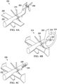
- modal tailboom flight control system 200 includes a vertical fin 202 coupled to the aft end of tailboom 204.
- Tail rotor 206 is rotatably coupled to vertical fin 202.
- Vertical fin 202 provides additional yaw stability and may eliminate the need for vertical fins at the outboard ends of horizontal stabilizer 208.
- Orienting tail rotor 206 at or near the top of vertical fin 202 elevates tail rotor 206 above tailboom 204 and at least partially offsets tail rotor 206 from the slipstream of pusher propeller 210.
- modal tailboom flight control system 214 includes tail rotor 216 with a surrounding duct 218 and forward vertical fin 220.
- Duct 218 may enhance the anti-torque thrust generated by tail rotor 216 or enable thrust vectoring. Duct 218 may also protect ground personnel from coming into contact with tail rotor blades 222.
- Forward vertical fin 220 provides yaw stability while protecting tail rotor blades 222 from debris during forward flight. Forward vertical fin 220 also reduces the amount of drag caused by tail rotor 216 being in the slipstream of pusher propeller 224.
- the anti-torque system of modal tailboom flight control system 228 is a cross-flow fan 230, eliminating the need for a tail rotor.
- Cross-flow fan 230 is disposed on and rotates about the centerline of tailboom 232.
- Cross-flow fan 230 may be a variable thrust cross-flow fan having a plurality of blades 234 disposed radially outward from the centerline of tailboom 232 such that blades 234 have a generally circular path of travel when cross-flow fan 230 rotates about the centerline of tailboom 232.
- Blades 234 may be movable between a plurality of pitch angle configurations to generate thrust in either the torque or anti-torque directions.
- modal tailboom flight control system 238 includes a ducted pusher propeller 240 forward of tail rotor 242.
- Duct 244 protects ducted pusher propeller blades 246 during flight and protects ground personnel from contacting ducted pusher propeller blades 246.
- Duct 244 may also enable thrust vectoring to enable ducted pusher propeller 240 to emit thrust in different directions.
- Ducted pusher propeller 240 includes vertical fins 248 and horizontal fins 250 for yaw and pitch stability as well as to protect ducted pusher propeller blades 246.
- both ducted pusher propeller 240 and tail rotor 242 may include a duct.
Landscapes
- Engineering & Computer Science (AREA)
- Mechanical Engineering (AREA)
- Aviation & Aerospace Engineering (AREA)
- Toys (AREA)
Claims (15)
- Système de commande de vol de longeron d'empennage modal (20, 102) configuré pour être attaché à un hélicoptère à hélice propulsive arrière (10, 104), le système de commande de vol de longeron d'empennage modal (20, 102) étant actionnable dans une pluralité de modes comportant un mode de poussée vers l'avant et un mode anti-couple, le système de commande de vol de longeron d'empennage modal (20, 102) comprenant :un longeron d'empennage (22, 116) ;un train d'entraînement (100) s'étendant à travers le longeron d'empennage (22, 116) ;un système anti-couple (24) couplé au train d'entraînement (100) et rotatif pour générer une poussée anti-couple pour l'hélicoptère à hélice propulsive arrière (10, 104) dans le mode anti-couple ; etune hélice propulsive (32, 106) couplée au train d'entraînement (100) et rotative pour générer une poussée vers l'avant pour l'hélicoptère à hélice propulsive arrière (10, 104) dans le mode de poussée vers l'avant ;caractérisé en ce que l'hélice propulsive (32, 106) est positionnée vers l'avant du système anti-couple (24).
- Système de commande de vol de longeron d'empennage modal (20, 102) selon la revendication 1, dans lequel le système de commande de vol de longeron d'empennage modal (20, 102) est configuré de sorte que, dans le mode de poussée vers l'avant, la vitesse rotative de l'hélice propulsive (32, 106) augmente par rapport à la vitesse de rotation du système anti-couple (24) et de sorte que, dans le mode anti-couple, la vitesse de rotation de l'hélice propulsive (32, 106) diminue par rapport à la vitesse de rotation du système anti-couple (24).
- Système de commande de vol de longeron d'empennage modal (20, 102) selon la revendication 1 ou selon la revendication 2, dans lequel l'hélice propulsive (32, 106) et le système anti-couple (24) comprennent chacun en outre des pales de rotor à calage variable ;dans lequel les pales de rotor à calage variable de l'hélice propulsive (32, 106) sont calées pour augmenter la poussée vers l'avant générée par l'hélice propulsive (32, 106) dans le mode de poussée vers l'avant ; etdans lequel les pales de rotor à calage variable du système anti-couple (24) sont calées pour augmenter la poussée anti-couple générée par le système anti-couple (24) dans le mode anti-couple.
- Système de commande de vol de longeron d'empennage modal (20, 102) selon la revendication 1 ou la revendication 2 ou la revendication 3, dans lequel l'hélicoptère à hélice propulsive arrière (10, 104) est actionnable dans un mode de vol vers l'avant et un mode de décollage et d'atterrissage ; et
dans lequel le système de commande de vol de longeron d'empennage modal (20, 102) est dans le mode de poussée vers l'avant lorsque l'hélicoptère à hélice propulsive arrière (10, 104) est dans le mode de vol vers l'avant et dans le mode anti-couple lorsque l'hélicoptère à hélice propulsive arrière (10, 104) est dans le mode de décollage vertical et d'atterrissage. - Système de commande de vol de longeron d'empennage modal (20, 102) selon la revendication 1 ou l'une quelconque des revendications 2 à 4, dans lequel le système anti-couple (24) comprend en outre un rotor anti-couple (26, 108, 206, 216).
- Système de commande de vol de longeron d'empennage modal (20, 102) selon la revendication 5, dans lequel :-(i) le rotor anti-couple (26, 108, 206, 216) comprend en outre un ensemble de moyeu de rotor anti-couple décalé d'une distance D d'une ligne centrale (36) de l'hélicoptère à hélice propulsive arrière (10, 104) ;dans lequel l'hélice propulsive (32, 106) présente un rayon R ; etdans lequel D < R ; et/ ou(ii) D < R/2.
- Système de commande de vol de longeron d'empennage modal (20, 102) selon la revendication 1 ou l'une quelconque des revendications 2 à 6, dans lequel l'hélice propulsive (32, 106) comprend en outre un carénage de moyeu de rotor (60) affleurant sensiblement le longeron d'empennage (22, 116).
- Système de commande de vol de longeron d'empennage modal (20, 102) selon la revendication 1 ou l'une quelconque des revendications 2 à 7, comprenant en outre un stabilisateur de vol (38) positionné vers l'avant de l'hélice propulsive (32, 106).
- Système de commande de vol de longeron d'empennage modal (20, 102) selon la revendication 8, dans lequel :-(i) le stabilisateur de vol (38) obstrue au moins partiellement un côté vers l'avant de l'hélice propulsive (32, 106) pour protéger l'hélice propulsive (32, 106) ; et/ou(ii) le stabilisateur de vol (38) comprend en outre un stabilisateur horizontal (40).
- Système de commande de vol de longeron d'empennage modal (20, 102) selon la revendication 9, partie (ii), dans lequel :(a) l'hélice propulsive (32, 106) présente un diamètre D ;dans lequel le stabilisateur horizontal (40) présente une largeur W ; etdans lequel D < W ; et/ou(b) le système anti-couple (24) comprend en outre un ensemble de moyeu de rotor anti-couple décalé d'une distance D d'une ligne centrale (36) de l'hélicoptère à hélice propulsive arrière (10, 104) ;dans lequel le stabilisateur horizontal (40) présente une largeur W ; etdans lequel D < W/2.
- Système de commande de vol de longeron d'empennage modal (20, 102) selon la revendication 9, partie (ii), ou selon la revendication 10, dans lequel le stabilisateur de vol (38) comprend en outre des ailettes verticales (42, 248) couplées aux extrémités extérieures du stabilisateur horizontal (40).
- Hélicoptère à hélice propulsive arrière (10, 104) comprenant :un fuselage (18) ; etun système de commande de vol de longeron d'empennage modal (20, 102) selon l'une quelconque des revendications précédentes, le système de commande de vol longeron d'empennage modal (20, 102) étant couplé au fuselage (18).
- Hélicoptère à hélice propulsive arrière (10, 104) selon la revendication 12, dans lequel :-(i) le train d'entraînement (100) comprend en outre un embrayage d'hélice propulsive (122) et un embrayage de système anti-couple (124) ; et
dans lequel les vitesses de rotation de l'hélice propulsive (32, 106) et le système anti-couple (24) sont commandables de manière indépendante en utilisant l'embrayage d'hélice propulsive (122) et l'embrayage de système anti-couple (124) ;
et/ou(ii) le train d'entraînement (100) comprend en outre un arbre d'entraînement d'extension (114a) à l'arrière de l'hélice propulsive (32, 106) pour transmettre l'énergie de rotation au système anti-couple (24). - Hélicoptère à hélice propulsive arrière (10, 104) selon la revendication 12 ou la revendication 13, comprenant en outre des première et seconde ailes (46, 48) faisant saillie des côtés du fuselage, et en option ou de préférence dans lequel le système de commande de vol de longeron d'empennage modal (20, 102) comprend en outre un stabilisateur de vol (38) positionné vers l'avant de l'hélice propulsive (32, 106), le stabilisateur de vol (38) présentant une largeur W ;dans lequel les première et seconde ailes (46, 48) forment une envergure d'aile Z ; etdans lequel W < Z.
- Hélicoptère à hélice propulsive arrière (10, 104) selon la revendication 12 ou la revendication 13 ou la revendication 14, dans lequel le mode du système de commande de vol de longeron d'empennage modal (20,102) est commutable sur la base d'une entrée de pilote.
Applications Claiming Priority (1)
| Application Number | Priority Date | Filing Date | Title |
|---|---|---|---|
| US16/247,817 US10933990B2 (en) | 2019-01-15 | 2019-01-15 | Modal tailboom flight control systems for compound helicopters |
Publications (2)
| Publication Number | Publication Date |
|---|---|
| EP3683143A1 EP3683143A1 (fr) | 2020-07-22 |
| EP3683143B1 true EP3683143B1 (fr) | 2022-03-09 |
Family
ID=69156210
Family Applications (1)
| Application Number | Title | Priority Date | Filing Date |
|---|---|---|---|
| EP20150763.9A Active EP3683143B1 (fr) | 2019-01-15 | 2020-01-08 | Systèmes de commande de vol modaux de poutre de queue pour hélicoptères composés |
Country Status (2)
| Country | Link |
|---|---|
| US (1) | US10933990B2 (fr) |
| EP (1) | EP3683143B1 (fr) |
Families Citing this family (11)
| Publication number | Priority date | Publication date | Assignee | Title |
|---|---|---|---|---|
| US12404018B2 (en) | 2014-03-11 | 2025-09-02 | Jaunt Air Mobility | Mast dampener for a rotorcraft |
| US11174016B2 (en) * | 2018-05-03 | 2021-11-16 | Jaunt Air Mobility, Llc | Compound rotorcraft with propeller |
| US12049304B2 (en) * | 2019-02-05 | 2024-07-30 | Textron Innovations Inc. | Tail rotor isolation systems for rotorcraft |
| US11718394B2 (en) * | 2019-04-16 | 2023-08-08 | The Boeing Company | Anti-torque and propulsion system for rotorcraft |
| USD902122S1 (en) * | 2019-09-27 | 2020-11-17 | Bell Textron Inc. | Pair of aircraft wings |
| USD894814S1 (en) * | 2019-09-27 | 2020-09-01 | Bell Textron Inc. | Aircraft |
| USD896730S1 (en) * | 2019-09-27 | 2020-09-22 | Bell Textron Inc. | Combined aircraft fuselage and empennage |
| US11572155B2 (en) * | 2019-10-28 | 2023-02-07 | Textron Innovations Inc. | Rotorcraft having propeller generated power during autorotations |
| US11993391B1 (en) * | 2021-02-16 | 2024-05-28 | Piasecki Aircraft Corporation | Apparatus, system and method for storage of hydrogen on board a hydrogen-fueled aircraft |
| US11299287B1 (en) | 2021-06-29 | 2022-04-12 | Beta Air, Llc | Methods and systems for orienting a thrust propulsor in response to a failure event of a vertical take-off and landing aircraft |
| CN116124407B (zh) * | 2023-04-10 | 2023-06-13 | 中国空气动力研究与发展中心低速空气动力研究所 | 获取雷达尾流对直升机尾部件气动特性影响的试验方法 |
Family Cites Families (17)
| Publication number | Priority date | Publication date | Assignee | Title |
|---|---|---|---|---|
| US2698147A (en) * | 1950-09-01 | 1954-12-28 | Paul E Hovgard | Aircraft with fixed wings and lifting rotor |
| US3105659A (en) | 1962-03-30 | 1963-10-01 | United Aircraft Corp | Compound helicopter |
| US3448946A (en) * | 1966-09-16 | 1969-06-10 | Kawasaki Kokuki Kogyo Kk | Compound helicopter |
| US3563496A (en) * | 1967-06-12 | 1971-02-16 | Daniel R Zuck | Compound helicopter |
| US3540680A (en) * | 1968-05-24 | 1970-11-17 | Lockheed Aircraft Corp | Dual rotor system for helicopters |
| US4632337A (en) * | 1981-09-21 | 1986-12-30 | Hughes Helicopters, Inc. | Helicopter rotor transmission systems |
| US4531692A (en) * | 1982-03-15 | 1985-07-30 | Ernesto Mateus | Helicopter flight control and transmission system |
| US4514142A (en) | 1982-04-01 | 1985-04-30 | The United States Of America As Represented By The Secretary Of The Army | Power management process |
| US4928907A (en) | 1988-02-29 | 1990-05-29 | Y & B Investment Corporation | Compound helicopter with no tail rotor |
| FR2736889B1 (fr) * | 1995-07-21 | 1997-09-12 | Eurocopter France | Aeronef a voilure tournante du type combine et element structurel arriere pour un tel aeronef |
| US20050151001A1 (en) | 2003-07-02 | 2005-07-14 | Loper Arthur W. | Compound helicopter |
| US7438259B1 (en) * | 2006-08-16 | 2008-10-21 | Piasecki Aircraft Corporation | Compound aircraft control system and method |
| FR2983171B1 (fr) * | 2011-11-30 | 2014-03-21 | Eurocopter France | Dispositif anti-couple a poussee longitudinale pour un giravion |
| CN102700708A (zh) | 2012-06-08 | 2012-10-03 | 朱清华 | 直升机增速尾部装置 |
| US10703471B2 (en) * | 2016-06-03 | 2020-07-07 | Bell Helicopter Textron Inc. | Anti-torque control using matrix of fixed blade pitch motor modules |
| US10526085B2 (en) | 2016-06-03 | 2020-01-07 | Bell Textron Inc. | Electric distributed propulsion anti-torque redundant power and control system |
| US10858116B2 (en) * | 2018-09-04 | 2020-12-08 | Textron Innovations Inc. | Pusher rotorcraft drivetrain |
-
2019
- 2019-01-15 US US16/247,817 patent/US10933990B2/en active Active
-
2020
- 2020-01-08 EP EP20150763.9A patent/EP3683143B1/fr active Active
Also Published As
| Publication number | Publication date |
|---|---|
| US20200223540A1 (en) | 2020-07-16 |
| EP3683143A1 (fr) | 2020-07-22 |
| US10933990B2 (en) | 2021-03-02 |
Similar Documents
| Publication | Publication Date | Title |
|---|---|---|
| EP3683143B1 (fr) | Systèmes de commande de vol modaux de poutre de queue pour hélicoptères composés | |
| US11713113B2 (en) | Compound rotorcraft with propeller | |
| EP3201079B1 (fr) | Commande de vitesse de rotation de rotor principal pour giravion | |
| EP3000722B1 (fr) | Avion | |
| EP3483065B1 (fr) | Aéronef à multirotor comportant un collectif pour autorotation | |
| US10822076B2 (en) | Dual rotor, rotary wing aircraft | |
| US8668162B1 (en) | Apparatus and method for roll moment equalization at high advance ratios for rotary wing aircraft | |
| US20230056974A1 (en) | Stowable Lift Rotors for VTOL Aircraft | |
| US10737776B2 (en) | Apparatus and method for roll moment equalization at high advance ratios for rotary wing aircraft | |
| US12202600B1 (en) | High-speed tiltrotor aircraft having a variable-sweep wing | |
| US20240278909A1 (en) | Rotor position control system | |
| US11572155B2 (en) | Rotorcraft having propeller generated power during autorotations | |
| US10703472B2 (en) | Directional control for coaxial rotary wing craft |
Legal Events
| Date | Code | Title | Description |
|---|---|---|---|
| STAA | Information on the status of an ep patent application or granted ep patent |
Free format text: STATUS: EXAMINATION IS IN PROGRESS |
|
| PUAI | Public reference made under article 153(3) epc to a published international application that has entered the european phase |
Free format text: ORIGINAL CODE: 0009012 |
|
| 17P | Request for examination filed |
Effective date: 20200108 |
|
| AK | Designated contracting states |
Kind code of ref document: A1 Designated state(s): AL AT BE BG CH CY CZ DE DK EE ES FI FR GB GR HR HU IE IS IT LI LT LU LV MC MK MT NL NO PL PT RO RS SE SI SK SM TR |
|
| AX | Request for extension of the european patent |
Extension state: BA ME |
|
| GRAP | Despatch of communication of intention to grant a patent |
Free format text: ORIGINAL CODE: EPIDOSNIGR1 |
|
| STAA | Information on the status of an ep patent application or granted ep patent |
Free format text: STATUS: GRANT OF PATENT IS INTENDED |
|
| INTG | Intention to grant announced |
Effective date: 20211125 |
|
| GRAS | Grant fee paid |
Free format text: ORIGINAL CODE: EPIDOSNIGR3 |
|
| GRAA | (expected) grant |
Free format text: ORIGINAL CODE: 0009210 |
|
| STAA | Information on the status of an ep patent application or granted ep patent |
Free format text: STATUS: THE PATENT HAS BEEN GRANTED |
|
| RAP1 | Party data changed (applicant data changed or rights of an application transferred) |
Owner name: TEXTRON INNOVATIONS INC. |
|
| AK | Designated contracting states |
Kind code of ref document: B1 Designated state(s): AL AT BE BG CH CY CZ DE DK EE ES FI FR GB GR HR HU IE IS IT LI LT LU LV MC MK MT NL NO PL PT RO RS SE SI SK SM TR |
|
| REG | Reference to a national code |
Ref country code: CH Ref legal event code: EP Ref country code: AT Ref legal event code: REF Ref document number: 1473956 Country of ref document: AT Kind code of ref document: T Effective date: 20220315 |
|
| REG | Reference to a national code |
Ref country code: DE Ref legal event code: R096 Ref document number: 602020002068 Country of ref document: DE |
|
| REG | Reference to a national code |
Ref country code: IE Ref legal event code: FG4D |
|
| REG | Reference to a national code |
Ref country code: LT Ref legal event code: MG9D |
|
| REG | Reference to a national code |
Ref country code: NL Ref legal event code: MP Effective date: 20220309 |
|
| PG25 | Lapsed in a contracting state [announced via postgrant information from national office to epo] |
Ref country code: SE Free format text: LAPSE BECAUSE OF FAILURE TO SUBMIT A TRANSLATION OF THE DESCRIPTION OR TO PAY THE FEE WITHIN THE PRESCRIBED TIME-LIMIT Effective date: 20220309 Ref country code: RS Free format text: LAPSE BECAUSE OF FAILURE TO SUBMIT A TRANSLATION OF THE DESCRIPTION OR TO PAY THE FEE WITHIN THE PRESCRIBED TIME-LIMIT Effective date: 20220309 Ref country code: NO Free format text: LAPSE BECAUSE OF FAILURE TO SUBMIT A TRANSLATION OF THE DESCRIPTION OR TO PAY THE FEE WITHIN THE PRESCRIBED TIME-LIMIT Effective date: 20220609 Ref country code: LT Free format text: LAPSE BECAUSE OF FAILURE TO SUBMIT A TRANSLATION OF THE DESCRIPTION OR TO PAY THE FEE WITHIN THE PRESCRIBED TIME-LIMIT Effective date: 20220309 Ref country code: HR Free format text: LAPSE BECAUSE OF FAILURE TO SUBMIT A TRANSLATION OF THE DESCRIPTION OR TO PAY THE FEE WITHIN THE PRESCRIBED TIME-LIMIT Effective date: 20220309 Ref country code: BG Free format text: LAPSE BECAUSE OF FAILURE TO SUBMIT A TRANSLATION OF THE DESCRIPTION OR TO PAY THE FEE WITHIN THE PRESCRIBED TIME-LIMIT Effective date: 20220609 |
|
| REG | Reference to a national code |
Ref country code: AT Ref legal event code: MK05 Ref document number: 1473956 Country of ref document: AT Kind code of ref document: T Effective date: 20220309 |
|
| PG25 | Lapsed in a contracting state [announced via postgrant information from national office to epo] |
Ref country code: LV Free format text: LAPSE BECAUSE OF FAILURE TO SUBMIT A TRANSLATION OF THE DESCRIPTION OR TO PAY THE FEE WITHIN THE PRESCRIBED TIME-LIMIT Effective date: 20220309 Ref country code: GR Free format text: LAPSE BECAUSE OF FAILURE TO SUBMIT A TRANSLATION OF THE DESCRIPTION OR TO PAY THE FEE WITHIN THE PRESCRIBED TIME-LIMIT Effective date: 20220610 Ref country code: FI Free format text: LAPSE BECAUSE OF FAILURE TO SUBMIT A TRANSLATION OF THE DESCRIPTION OR TO PAY THE FEE WITHIN THE PRESCRIBED TIME-LIMIT Effective date: 20220309 |
|
| PG25 | Lapsed in a contracting state [announced via postgrant information from national office to epo] |
Ref country code: NL Free format text: LAPSE BECAUSE OF FAILURE TO SUBMIT A TRANSLATION OF THE DESCRIPTION OR TO PAY THE FEE WITHIN THE PRESCRIBED TIME-LIMIT Effective date: 20220309 |
|
| PG25 | Lapsed in a contracting state [announced via postgrant information from national office to epo] |
Ref country code: SM Free format text: LAPSE BECAUSE OF FAILURE TO SUBMIT A TRANSLATION OF THE DESCRIPTION OR TO PAY THE FEE WITHIN THE PRESCRIBED TIME-LIMIT Effective date: 20220309 Ref country code: SK Free format text: LAPSE BECAUSE OF FAILURE TO SUBMIT A TRANSLATION OF THE DESCRIPTION OR TO PAY THE FEE WITHIN THE PRESCRIBED TIME-LIMIT Effective date: 20220309 Ref country code: RO Free format text: LAPSE BECAUSE OF FAILURE TO SUBMIT A TRANSLATION OF THE DESCRIPTION OR TO PAY THE FEE WITHIN THE PRESCRIBED TIME-LIMIT Effective date: 20220309 Ref country code: PT Free format text: LAPSE BECAUSE OF FAILURE TO SUBMIT A TRANSLATION OF THE DESCRIPTION OR TO PAY THE FEE WITHIN THE PRESCRIBED TIME-LIMIT Effective date: 20220711 Ref country code: ES Free format text: LAPSE BECAUSE OF FAILURE TO SUBMIT A TRANSLATION OF THE DESCRIPTION OR TO PAY THE FEE WITHIN THE PRESCRIBED TIME-LIMIT Effective date: 20220309 Ref country code: EE Free format text: LAPSE BECAUSE OF FAILURE TO SUBMIT A TRANSLATION OF THE DESCRIPTION OR TO PAY THE FEE WITHIN THE PRESCRIBED TIME-LIMIT Effective date: 20220309 Ref country code: CZ Free format text: LAPSE BECAUSE OF FAILURE TO SUBMIT A TRANSLATION OF THE DESCRIPTION OR TO PAY THE FEE WITHIN THE PRESCRIBED TIME-LIMIT Effective date: 20220309 Ref country code: AT Free format text: LAPSE BECAUSE OF FAILURE TO SUBMIT A TRANSLATION OF THE DESCRIPTION OR TO PAY THE FEE WITHIN THE PRESCRIBED TIME-LIMIT Effective date: 20220309 |
|
| PG25 | Lapsed in a contracting state [announced via postgrant information from national office to epo] |
Ref country code: PL Free format text: LAPSE BECAUSE OF FAILURE TO SUBMIT A TRANSLATION OF THE DESCRIPTION OR TO PAY THE FEE WITHIN THE PRESCRIBED TIME-LIMIT Effective date: 20220309 Ref country code: IS Free format text: LAPSE BECAUSE OF FAILURE TO SUBMIT A TRANSLATION OF THE DESCRIPTION OR TO PAY THE FEE WITHIN THE PRESCRIBED TIME-LIMIT Effective date: 20220709 Ref country code: AL Free format text: LAPSE BECAUSE OF FAILURE TO SUBMIT A TRANSLATION OF THE DESCRIPTION OR TO PAY THE FEE WITHIN THE PRESCRIBED TIME-LIMIT Effective date: 20220309 |
|
| REG | Reference to a national code |
Ref country code: DE Ref legal event code: R097 Ref document number: 602020002068 Country of ref document: DE |
|
| PLBE | No opposition filed within time limit |
Free format text: ORIGINAL CODE: 0009261 |
|
| STAA | Information on the status of an ep patent application or granted ep patent |
Free format text: STATUS: NO OPPOSITION FILED WITHIN TIME LIMIT |
|
| PG25 | Lapsed in a contracting state [announced via postgrant information from national office to epo] |
Ref country code: DK Free format text: LAPSE BECAUSE OF FAILURE TO SUBMIT A TRANSLATION OF THE DESCRIPTION OR TO PAY THE FEE WITHIN THE PRESCRIBED TIME-LIMIT Effective date: 20220309 |
|
| 26N | No opposition filed |
Effective date: 20221212 |
|
| PG25 | Lapsed in a contracting state [announced via postgrant information from national office to epo] |
Ref country code: SI Free format text: LAPSE BECAUSE OF FAILURE TO SUBMIT A TRANSLATION OF THE DESCRIPTION OR TO PAY THE FEE WITHIN THE PRESCRIBED TIME-LIMIT Effective date: 20220309 |
|
| P01 | Opt-out of the competence of the unified patent court (upc) registered |
Effective date: 20230602 |
|
| REG | Reference to a national code |
Ref country code: CH Ref legal event code: PL |
|
| PG25 | Lapsed in a contracting state [announced via postgrant information from national office to epo] |
Ref country code: LU Free format text: LAPSE BECAUSE OF NON-PAYMENT OF DUE FEES Effective date: 20230108 |
|
| REG | Reference to a national code |
Ref country code: BE Ref legal event code: MM Effective date: 20230131 |
|
| PG25 | Lapsed in a contracting state [announced via postgrant information from national office to epo] |
Ref country code: LI Free format text: LAPSE BECAUSE OF NON-PAYMENT OF DUE FEES Effective date: 20230131 Ref country code: CH Free format text: LAPSE BECAUSE OF NON-PAYMENT OF DUE FEES Effective date: 20230131 |
|
| PG25 | Lapsed in a contracting state [announced via postgrant information from national office to epo] |
Ref country code: BE Free format text: LAPSE BECAUSE OF NON-PAYMENT OF DUE FEES Effective date: 20230131 |
|
| PG25 | Lapsed in a contracting state [announced via postgrant information from national office to epo] |
Ref country code: IE Free format text: LAPSE BECAUSE OF NON-PAYMENT OF DUE FEES Effective date: 20230108 |
|
| PG25 | Lapsed in a contracting state [announced via postgrant information from national office to epo] |
Ref country code: MC Free format text: LAPSE BECAUSE OF FAILURE TO SUBMIT A TRANSLATION OF THE DESCRIPTION OR TO PAY THE FEE WITHIN THE PRESCRIBED TIME-LIMIT Effective date: 20220309 |
|
| PG25 | Lapsed in a contracting state [announced via postgrant information from national office to epo] |
Ref country code: MC Free format text: LAPSE BECAUSE OF FAILURE TO SUBMIT A TRANSLATION OF THE DESCRIPTION OR TO PAY THE FEE WITHIN THE PRESCRIBED TIME-LIMIT Effective date: 20220309 |
|
| PG25 | Lapsed in a contracting state [announced via postgrant information from national office to epo] |
Ref country code: CY Free format text: LAPSE BECAUSE OF FAILURE TO SUBMIT A TRANSLATION OF THE DESCRIPTION OR TO PAY THE FEE WITHIN THE PRESCRIBED TIME-LIMIT; INVALID AB INITIO Effective date: 20200108 |
|
| PG25 | Lapsed in a contracting state [announced via postgrant information from national office to epo] |
Ref country code: HU Free format text: LAPSE BECAUSE OF FAILURE TO SUBMIT A TRANSLATION OF THE DESCRIPTION OR TO PAY THE FEE WITHIN THE PRESCRIBED TIME-LIMIT; INVALID AB INITIO Effective date: 20200108 |
|
| PG25 | Lapsed in a contracting state [announced via postgrant information from national office to epo] |
Ref country code: TR Free format text: LAPSE BECAUSE OF FAILURE TO SUBMIT A TRANSLATION OF THE DESCRIPTION OR TO PAY THE FEE WITHIN THE PRESCRIBED TIME-LIMIT Effective date: 20220309 |
|
| PGFP | Annual fee paid to national office [announced via postgrant information from national office to epo] |
Ref country code: GB Payment date: 20260127 Year of fee payment: 7 |
|
| PGFP | Annual fee paid to national office [announced via postgrant information from national office to epo] |
Ref country code: DE Payment date: 20260128 Year of fee payment: 7 |
|
| PGFP | Annual fee paid to national office [announced via postgrant information from national office to epo] |
Ref country code: IT Payment date: 20260121 Year of fee payment: 7 |
|
| PGFP | Annual fee paid to national office [announced via postgrant information from national office to epo] |
Ref country code: FR Payment date: 20260126 Year of fee payment: 7 |