EP3683162A1 - Contenant rotatif pour palette de gerbage - Google Patents
Contenant rotatif pour palette de gerbage Download PDFInfo
- Publication number
- EP3683162A1 EP3683162A1 EP19170269.5A EP19170269A EP3683162A1 EP 3683162 A1 EP3683162 A1 EP 3683162A1 EP 19170269 A EP19170269 A EP 19170269A EP 3683162 A1 EP3683162 A1 EP 3683162A1
- Authority
- EP
- European Patent Office
- Prior art keywords
- container
- pallet container
- edge
- pallet
- runners
- Prior art date
- Legal status (The legal status is an assumption and is not a legal conclusion. Google has not performed a legal analysis and makes no representation as to the accuracy of the status listed.)
- Granted
Links
Images


Classifications
-
- B—PERFORMING OPERATIONS; TRANSPORTING
- B65—CONVEYING; PACKING; STORING; HANDLING THIN OR FILAMENTARY MATERIAL
- B65D—CONTAINERS FOR STORAGE OR TRANSPORT OF ARTICLES OR MATERIALS, e.g. BAGS, BARRELS, BOTTLES, BOXES, CANS, CARTONS, CRATES, DRUMS, JARS, TANKS, HOPPERS, FORWARDING CONTAINERS; ACCESSORIES, CLOSURES, OR FITTINGS THEREFOR; PACKAGING ELEMENTS; PACKAGES
- B65D19/00—Pallets or like platforms, with or without side walls, for supporting loads to be lifted or lowered
- B65D19/02—Rigid pallets with side walls, e.g. box pallets
- B65D19/04—Rigid pallets with side walls, e.g. box pallets with bodies moulded or otherwise fabricated in one piece
-
- B—PERFORMING OPERATIONS; TRANSPORTING
- B65—CONVEYING; PACKING; STORING; HANDLING THIN OR FILAMENTARY MATERIAL
- B65D—CONTAINERS FOR STORAGE OR TRANSPORT OF ARTICLES OR MATERIALS, e.g. BAGS, BARRELS, BOTTLES, BOXES, CANS, CARTONS, CRATES, DRUMS, JARS, TANKS, HOPPERS, FORWARDING CONTAINERS; ACCESSORIES, CLOSURES, OR FITTINGS THEREFOR; PACKAGING ELEMENTS; PACKAGES
- B65D19/00—Pallets or like platforms, with or without side walls, for supporting loads to be lifted or lowered
- B65D19/38—Details or accessories
-
- B—PERFORMING OPERATIONS; TRANSPORTING
- B65—CONVEYING; PACKING; STORING; HANDLING THIN OR FILAMENTARY MATERIAL
- B65D—CONTAINERS FOR STORAGE OR TRANSPORT OF ARTICLES OR MATERIALS, e.g. BAGS, BARRELS, BOTTLES, BOXES, CANS, CARTONS, CRATES, DRUMS, JARS, TANKS, HOPPERS, FORWARDING CONTAINERS; ACCESSORIES, CLOSURES, OR FITTINGS THEREFOR; PACKAGING ELEMENTS; PACKAGES
- B65D21/00—Nestable, stackable or joinable containers; Containers of variable capacity
- B65D21/02—Containers specially shaped, or provided with fittings or attachments, to facilitate nesting, stacking, or joining together
- B65D21/0233—Nestable containers
-
- B—PERFORMING OPERATIONS; TRANSPORTING
- B65—CONVEYING; PACKING; STORING; HANDLING THIN OR FILAMENTARY MATERIAL
- B65D—CONTAINERS FOR STORAGE OR TRANSPORT OF ARTICLES OR MATERIALS, e.g. BAGS, BARRELS, BOTTLES, BOXES, CANS, CARTONS, CRATES, DRUMS, JARS, TANKS, HOPPERS, FORWARDING CONTAINERS; ACCESSORIES, CLOSURES, OR FITTINGS THEREFOR; PACKAGING ELEMENTS; PACKAGES
- B65D21/00—Nestable, stackable or joinable containers; Containers of variable capacity
- B65D21/02—Containers specially shaped, or provided with fittings or attachments, to facilitate nesting, stacking, or joining together
- B65D21/04—Open-ended containers shaped to be nested when empty and to be superposed when full
- B65D21/043—Identical stackable containers specially adapted for nesting after rotation around a vertical axis
-
- B—PERFORMING OPERATIONS; TRANSPORTING
- B65—CONVEYING; PACKING; STORING; HANDLING THIN OR FILAMENTARY MATERIAL
- B65D—CONTAINERS FOR STORAGE OR TRANSPORT OF ARTICLES OR MATERIALS, e.g. BAGS, BARRELS, BOTTLES, BOXES, CANS, CARTONS, CRATES, DRUMS, JARS, TANKS, HOPPERS, FORWARDING CONTAINERS; ACCESSORIES, CLOSURES, OR FITTINGS THEREFOR; PACKAGING ELEMENTS; PACKAGES
- B65D21/00—Nestable, stackable or joinable containers; Containers of variable capacity
- B65D21/02—Containers specially shaped, or provided with fittings or attachments, to facilitate nesting, stacking, or joining together
- B65D21/04—Open-ended containers shaped to be nested when empty and to be superposed when full
- B65D21/043—Identical stackable containers specially adapted for nesting after rotation around a vertical axis
- B65D21/045—Identical stackable containers specially adapted for nesting after rotation around a vertical axis about 180° only
-
- B—PERFORMING OPERATIONS; TRANSPORTING
- B65—CONVEYING; PACKING; STORING; HANDLING THIN OR FILAMENTARY MATERIAL
- B65D—CONTAINERS FOR STORAGE OR TRANSPORT OF ARTICLES OR MATERIALS, e.g. BAGS, BARRELS, BOTTLES, BOXES, CANS, CARTONS, CRATES, DRUMS, JARS, TANKS, HOPPERS, FORWARDING CONTAINERS; ACCESSORIES, CLOSURES, OR FITTINGS THEREFOR; PACKAGING ELEMENTS; PACKAGES
- B65D2519/00—Pallets or like platforms, with or without side walls, for supporting loads to be lifted or lowered
- B65D2519/00004—Details relating to pallets
- B65D2519/00009—Materials
- B65D2519/00014—Materials for the load supporting surface
- B65D2519/00034—Plastic
-
- B—PERFORMING OPERATIONS; TRANSPORTING
- B65—CONVEYING; PACKING; STORING; HANDLING THIN OR FILAMENTARY MATERIAL
- B65D—CONTAINERS FOR STORAGE OR TRANSPORT OF ARTICLES OR MATERIALS, e.g. BAGS, BARRELS, BOTTLES, BOXES, CANS, CARTONS, CRATES, DRUMS, JARS, TANKS, HOPPERS, FORWARDING CONTAINERS; ACCESSORIES, CLOSURES, OR FITTINGS THEREFOR; PACKAGING ELEMENTS; PACKAGES
- B65D2519/00—Pallets or like platforms, with or without side walls, for supporting loads to be lifted or lowered
- B65D2519/00004—Details relating to pallets
- B65D2519/00009—Materials
- B65D2519/00049—Materials for the base surface
- B65D2519/00069—Plastic
-
- B—PERFORMING OPERATIONS; TRANSPORTING
- B65—CONVEYING; PACKING; STORING; HANDLING THIN OR FILAMENTARY MATERIAL
- B65D—CONTAINERS FOR STORAGE OR TRANSPORT OF ARTICLES OR MATERIALS, e.g. BAGS, BARRELS, BOTTLES, BOXES, CANS, CARTONS, CRATES, DRUMS, JARS, TANKS, HOPPERS, FORWARDING CONTAINERS; ACCESSORIES, CLOSURES, OR FITTINGS THEREFOR; PACKAGING ELEMENTS; PACKAGES
- B65D2519/00—Pallets or like platforms, with or without side walls, for supporting loads to be lifted or lowered
- B65D2519/00004—Details relating to pallets
- B65D2519/00009—Materials
- B65D2519/00154—Materials for the side walls
- B65D2519/00174—Plastic
-
- B—PERFORMING OPERATIONS; TRANSPORTING
- B65—CONVEYING; PACKING; STORING; HANDLING THIN OR FILAMENTARY MATERIAL
- B65D—CONTAINERS FOR STORAGE OR TRANSPORT OF ARTICLES OR MATERIALS, e.g. BAGS, BARRELS, BOTTLES, BOXES, CANS, CARTONS, CRATES, DRUMS, JARS, TANKS, HOPPERS, FORWARDING CONTAINERS; ACCESSORIES, CLOSURES, OR FITTINGS THEREFOR; PACKAGING ELEMENTS; PACKAGES
- B65D2519/00—Pallets or like platforms, with or without side walls, for supporting loads to be lifted or lowered
- B65D2519/00004—Details relating to pallets
- B65D2519/00258—Overall construction
- B65D2519/00263—Overall construction of the pallet
- B65D2519/00268—Overall construction of the pallet made of one piece
-
- B—PERFORMING OPERATIONS; TRANSPORTING
- B65—CONVEYING; PACKING; STORING; HANDLING THIN OR FILAMENTARY MATERIAL
- B65D—CONTAINERS FOR STORAGE OR TRANSPORT OF ARTICLES OR MATERIALS, e.g. BAGS, BARRELS, BOTTLES, BOXES, CANS, CARTONS, CRATES, DRUMS, JARS, TANKS, HOPPERS, FORWARDING CONTAINERS; ACCESSORIES, CLOSURES, OR FITTINGS THEREFOR; PACKAGING ELEMENTS; PACKAGES
- B65D2519/00—Pallets or like platforms, with or without side walls, for supporting loads to be lifted or lowered
- B65D2519/00004—Details relating to pallets
- B65D2519/00258—Overall construction
- B65D2519/00283—Overall construction of the load supporting surface
- B65D2519/00288—Overall construction of the load supporting surface made of one piece
-
- B—PERFORMING OPERATIONS; TRANSPORTING
- B65—CONVEYING; PACKING; STORING; HANDLING THIN OR FILAMENTARY MATERIAL
- B65D—CONTAINERS FOR STORAGE OR TRANSPORT OF ARTICLES OR MATERIALS, e.g. BAGS, BARRELS, BOTTLES, BOXES, CANS, CARTONS, CRATES, DRUMS, JARS, TANKS, HOPPERS, FORWARDING CONTAINERS; ACCESSORIES, CLOSURES, OR FITTINGS THEREFOR; PACKAGING ELEMENTS; PACKAGES
- B65D2519/00—Pallets or like platforms, with or without side walls, for supporting loads to be lifted or lowered
- B65D2519/00004—Details relating to pallets
- B65D2519/00258—Overall construction
- B65D2519/00313—Overall construction of the base surface
- B65D2519/00318—Overall construction of the base surface made of one piece
-
- B—PERFORMING OPERATIONS; TRANSPORTING
- B65—CONVEYING; PACKING; STORING; HANDLING THIN OR FILAMENTARY MATERIAL
- B65D—CONTAINERS FOR STORAGE OR TRANSPORT OF ARTICLES OR MATERIALS, e.g. BAGS, BARRELS, BOTTLES, BOXES, CANS, CARTONS, CRATES, DRUMS, JARS, TANKS, HOPPERS, FORWARDING CONTAINERS; ACCESSORIES, CLOSURES, OR FITTINGS THEREFOR; PACKAGING ELEMENTS; PACKAGES
- B65D2519/00—Pallets or like platforms, with or without side walls, for supporting loads to be lifted or lowered
- B65D2519/00004—Details relating to pallets
- B65D2519/00258—Overall construction
- B65D2519/00313—Overall construction of the base surface
- B65D2519/00328—Overall construction of the base surface shape of the contact surface of the base
- B65D2519/00333—Overall construction of the base surface shape of the contact surface of the base contact surface having a stringer-like shape
-
- B—PERFORMING OPERATIONS; TRANSPORTING
- B65—CONVEYING; PACKING; STORING; HANDLING THIN OR FILAMENTARY MATERIAL
- B65D—CONTAINERS FOR STORAGE OR TRANSPORT OF ARTICLES OR MATERIALS, e.g. BAGS, BARRELS, BOTTLES, BOXES, CANS, CARTONS, CRATES, DRUMS, JARS, TANKS, HOPPERS, FORWARDING CONTAINERS; ACCESSORIES, CLOSURES, OR FITTINGS THEREFOR; PACKAGING ELEMENTS; PACKAGES
- B65D2519/00—Pallets or like platforms, with or without side walls, for supporting loads to be lifted or lowered
- B65D2519/00004—Details relating to pallets
- B65D2519/00258—Overall construction
- B65D2519/00313—Overall construction of the base surface
- B65D2519/00328—Overall construction of the base surface shape of the contact surface of the base
- B65D2519/00338—Overall construction of the base surface shape of the contact surface of the base contact surface having a discrete foot-like shape
-
- B—PERFORMING OPERATIONS; TRANSPORTING
- B65—CONVEYING; PACKING; STORING; HANDLING THIN OR FILAMENTARY MATERIAL
- B65D—CONTAINERS FOR STORAGE OR TRANSPORT OF ARTICLES OR MATERIALS, e.g. BAGS, BARRELS, BOTTLES, BOXES, CANS, CARTONS, CRATES, DRUMS, JARS, TANKS, HOPPERS, FORWARDING CONTAINERS; ACCESSORIES, CLOSURES, OR FITTINGS THEREFOR; PACKAGING ELEMENTS; PACKAGES
- B65D2519/00—Pallets or like platforms, with or without side walls, for supporting loads to be lifted or lowered
- B65D2519/00004—Details relating to pallets
- B65D2519/00258—Overall construction
- B65D2519/00398—Overall construction reinforcements
- B65D2519/00402—Integral, e.g. ribs
- B65D2519/00422—Integral, e.g. ribs on the walls
-
- B—PERFORMING OPERATIONS; TRANSPORTING
- B65—CONVEYING; PACKING; STORING; HANDLING THIN OR FILAMENTARY MATERIAL
- B65D—CONTAINERS FOR STORAGE OR TRANSPORT OF ARTICLES OR MATERIALS, e.g. BAGS, BARRELS, BOTTLES, BOXES, CANS, CARTONS, CRATES, DRUMS, JARS, TANKS, HOPPERS, FORWARDING CONTAINERS; ACCESSORIES, CLOSURES, OR FITTINGS THEREFOR; PACKAGING ELEMENTS; PACKAGES
- B65D2519/00—Pallets or like platforms, with or without side walls, for supporting loads to be lifted or lowered
- B65D2519/00004—Details relating to pallets
- B65D2519/00258—Overall construction
- B65D2519/00492—Overall construction of the side walls
- B65D2519/00497—Overall construction of the side walls whereby at least one side wall is made of one piece
-
- B—PERFORMING OPERATIONS; TRANSPORTING
- B65—CONVEYING; PACKING; STORING; HANDLING THIN OR FILAMENTARY MATERIAL
- B65D—CONTAINERS FOR STORAGE OR TRANSPORT OF ARTICLES OR MATERIALS, e.g. BAGS, BARRELS, BOTTLES, BOXES, CANS, CARTONS, CRATES, DRUMS, JARS, TANKS, HOPPERS, FORWARDING CONTAINERS; ACCESSORIES, CLOSURES, OR FITTINGS THEREFOR; PACKAGING ELEMENTS; PACKAGES
- B65D2519/00—Pallets or like platforms, with or without side walls, for supporting loads to be lifted or lowered
- B65D2519/00004—Details relating to pallets
- B65D2519/00547—Connections
- B65D2519/00577—Connections structures connecting side walls, including corner posts, to each other
- B65D2519/00616—Connections structures connecting side walls, including corner posts, to each other structures not intended to be disassembled
- B65D2519/00621—Connections structures connecting side walls, including corner posts, to each other structures not intended to be disassembled sidewalls directly connected to each other
-
- B—PERFORMING OPERATIONS; TRANSPORTING
- B65—CONVEYING; PACKING; STORING; HANDLING THIN OR FILAMENTARY MATERIAL
- B65D—CONTAINERS FOR STORAGE OR TRANSPORT OF ARTICLES OR MATERIALS, e.g. BAGS, BARRELS, BOTTLES, BOXES, CANS, CARTONS, CRATES, DRUMS, JARS, TANKS, HOPPERS, FORWARDING CONTAINERS; ACCESSORIES, CLOSURES, OR FITTINGS THEREFOR; PACKAGING ELEMENTS; PACKAGES
- B65D2519/00—Pallets or like platforms, with or without side walls, for supporting loads to be lifted or lowered
- B65D2519/00004—Details relating to pallets
- B65D2519/00547—Connections
- B65D2519/00636—Connections structures connecting side walls to the pallet
- B65D2519/00666—Structures not intended to be disassembled
-
- B—PERFORMING OPERATIONS; TRANSPORTING
- B65—CONVEYING; PACKING; STORING; HANDLING THIN OR FILAMENTARY MATERIAL
- B65D—CONTAINERS FOR STORAGE OR TRANSPORT OF ARTICLES OR MATERIALS, e.g. BAGS, BARRELS, BOTTLES, BOXES, CANS, CARTONS, CRATES, DRUMS, JARS, TANKS, HOPPERS, FORWARDING CONTAINERS; ACCESSORIES, CLOSURES, OR FITTINGS THEREFOR; PACKAGING ELEMENTS; PACKAGES
- B65D2519/00—Pallets or like platforms, with or without side walls, for supporting loads to be lifted or lowered
- B65D2519/00004—Details relating to pallets
- B65D2519/00736—Details
- B65D2519/00935—Details with special means for nesting or stacking
- B65D2519/0094—Details with special means for nesting or stacking nestable
-
- B—PERFORMING OPERATIONS; TRANSPORTING
- B65—CONVEYING; PACKING; STORING; HANDLING THIN OR FILAMENTARY MATERIAL
- B65D—CONTAINERS FOR STORAGE OR TRANSPORT OF ARTICLES OR MATERIALS, e.g. BAGS, BARRELS, BOTTLES, BOXES, CANS, CARTONS, CRATES, DRUMS, JARS, TANKS, HOPPERS, FORWARDING CONTAINERS; ACCESSORIES, CLOSURES, OR FITTINGS THEREFOR; PACKAGING ELEMENTS; PACKAGES
- B65D2519/00—Pallets or like platforms, with or without side walls, for supporting loads to be lifted or lowered
- B65D2519/00004—Details relating to pallets
- B65D2519/00736—Details
- B65D2519/00935—Details with special means for nesting or stacking
- B65D2519/00955—Details with special means for nesting or stacking stackable
- B65D2519/00965—Details with special means for nesting or stacking stackable when loaded
- B65D2519/00975—Details with special means for nesting or stacking stackable when loaded through the side walls
Definitions
- the present disclosure relates to an optionally nestable or nested and stackable pallet container, in particular a large load carrier, with a bottom, side walls that expand conically and / or in steps from the bottom to a peripheral container edge, and runners extending below the bottom.
- Rotatable stackable pallet container which has side walls widening towards the container opening, which are designed in such a way that in a relative orientation of two structurally identical unfilled pallet containers, the pallet containers can be nested to reduce the transport volume during empty transport and in another relative orientation there are lower sections of the side walls can support one of the two pallet containers on upper sections of the side walls of the other pallet container and thus stack the pallet containers on one another is made possible.
- the ability to stack and rotate is implemented by means of projections provided on the outside of the side walls and by means of corresponding indentations on the inside of the side walls.
- a pallet container which has a bottom, in particular a rectangular base, and side walls which extend from the bottom to a container edge.
- the container also has a pallet-shaped base part which extends below the base and is adapted for engagement by a fork of a forklift truck or other industrial truck.
- the side walls extend conically and / or in steps widening from the floor upwards to a peripheral container edge.
- runners From the floor extend downwards, in particular two runners that run parallel to one another at least in sections.
- the runners each have at least two engagement openings, which enable an fork of a forklift truck or other industrial truck to engage.
- the bottom and the side walls are shaped in such a way that the pallet container can be nested in an identically orientated identical pallet container and can be stacked on an identical identical pallet container with respect to the pallet container only with respect to a vertical axis of the pallet container or a vertical axis of the identical pallet container.
- the vertical axis of the pallet container extends in particular perpendicular to the floor.
- the vertical axis extends through a center of the floor.
- the pallet container is characterized by the fact that the outer contour of the runners follows the outer contour of the side walls.
- the outer contour of the runners can follow the outer contour of the side walls flush at least in sections.
- the outer contour of the runners can follow the outer contour of the side walls insofar as these outer contours have a geometrically similar shape, at least in sections. That means or it is also possible that a shoulder is formed between the runners and the side walls.
- External contour means in particular the silhouette of a surface facing outwards with respect to the vertical axis of the pallet container or the outline of a surface facing away from the vertical axis of the pallet container in a sectional view parallel to the floor.
- That the outer contour of the runners follows the outer contour of the side walls means in particular that the shape of the outer contour of at least a large part of the runners corresponds to the shape of the outer contour of at least a large part of the side wall adjacent to the runners or is geometrically similar.
- “Flush” means in particular that the shape of the outer contour of the runners in an area immediately adjacent to the side walls corresponds to the shape of the outer contour of the side walls in an area immediately adjacent to the runners.
- the side walls have side wall recesses or indentations which are offset with respect to an adjacent, substantially parallel, section of the corresponding side wall in the direction of a container inner region, that is to say inwards, the
- the inner container area is the area which extends within the side walls above the bottom.
- the side walls have side wall recesses or indentations and not inwardly offset side wall sections.
- the side wall recesses or the indentations restrict the rotational symmetry of the pallet container in such a way that the pallet container can be stacked in the manner of a rotary stacking container in a relative orientation (first relative orientation) on an identical pallet container and in another relative orientation (second relative orientation) in an identical one Pallet container is nestable.
- the pallet container can be brought from the first relative orientation, in which the pallet container and the identical pallet container are oriented in opposite directions, by rotating through 180 ° about its vertical axis into the second relative orientation, in which the pallet container and the identical pallet container are oriented identically.
- first relative orientation sections of the side walls that are not offset inward are located above corresponding side wall recesses or indentations of the structurally identical pallet container.
- second relative orientation the side wall recesses or indentations of the pallet container are embedded in corresponding side wall recesses or indentations of the identical pallet container and are not embedded inwardly offset side wall sections of the pallet container in corresponding non-inwardly offset side wall sections of the identical pallet container.
- the skids each have at least one skid recess on a surface facing away from the interior of the container, which extends transversely, in particular perpendicularly, to the floor and along or at least largely parallel to a longitudinal direction of the respective skid, which is located below one of the side wall recesses.
- the skid recesses and the side wall recesses are each formed at least for the most part in a channel shape.
- the skid recess of one of the skids and the corresponding side wall recess merge. In other words, the skid recess of one of the skids and the corresponding sidewall recess together form a trough-shaped structure.
- the advantage of a pallet container according to the invention is that its orientation can be easily felt by moving one of the runners with one hand along an outer surface.
- the two runners each have an outer edge with at least one s-shaped section.
- each of the outer edges of the runners according to the invention has two rectilinear sections offset parallel to one another and a curved transition section connecting the sections offset parallel to one another.
- the shape of the s-shaped section of a respective runner corresponds to the shape of a cross section parallel to the floor of a part of the adjacent side wall.
- the two rectilinear sections of a respective runner are parallel to an edge of the bottom and one of the rectilinear sections extends closer to the interior of the container than the other rectilinear section.
- the at least two s-shaped sections of the outer edges of the runners can be designed such that they extend in a common (imaginary) plane.
- the orientation of the pallet container can be scanned from two sides in a similar and thus easier than usual manner.
- undersides of the runners facing away from the floor can also extend.
- the lower outer edges of the pallet container are sectionally S-shaped.
- Such an arrangement of the S-shaped sections on an underside of the pallet container makes it possible to scan the pallet container even when the pallet container is raised by an industrial truck.
- the outer edges of the runners can each have two end sections extending in a common (imaginary) straight line.
- the end sections of the respective runner can each be arranged in the region of a corner of the floor.
- Such an arrangement of the end sections of the outer edge of the respective runner makes it possible to ensure a defined tilting in a plane extending perpendicular to the outer edge.
- Recessing recesses can be provided on the circumferential container edge, on which lower support areas of the runners of the identical pallet container are supported when a structurally identical pallet container is stacked on the pallet container and in which the lower support regions of the runners of the identical pallet container are stacked when an identical pallet container is stacked on the pallet container can immerse.
- lower surfaces of the support recesses can extend in a common (imaginary) plane and lower surfaces of the engagement openings can extend in a (other) common (imaginary) plane.
- a depth of the support recesses of the pallet container can be determined such that it is less than or equal to a distance between the common plane of the lower surface of the engagement openings of the pallet container and the common plane of the lower surfaces of the support regions of the runners of the pallet container.
- the pallet container is designed in such a way that the depth of the support recesses and the distance between the common plane of the lower surfaces of the engagement openings and the common plane of the lower surfaces of the support regions of the runners ensure that the lower surfaces of the engagement openings do not lie below an upper edge of Container edges of an identical pallet container are when the pallet container is stacked on the identical pallet container.
- the support recesses and the runners are designed in this way, it is advantageously possible to inadvertently place the pallet container on a filled, identical pallet container in the second relative orientation that is actually intended for nesting by scanning the difference between one of the lower surfaces of the engagement openings of the pallet container and the to recognize the upper edge of the container edge of the filled identical pallet container.
- the edge of the container can be designed to protrude towards the outside of the container.
- the cantilevered container edge can more preferably cantilever at least on two opposite sides by more than 10 mm, so that said cantilevered edge is adapted from one side for engagement of a fork of a lift truck or other industrial truck.
- At least one recessed grip can be provided on an underside of the container edge, which is oriented such that the recessed grip can be reached from below.
- the pallet container nested in an identical pallet container can be manually separated from the identical pallet container.
- At an upper end of the at least one recessed grip at least one opening can be provided, which extends from the recessed grip in the direction away from the inner container region delimited by the floor and the side walls, that is to say to the outside, so that when the pallet container is superimposed on the head Handle recess collected water is at least partially removable to an outside of the pallet container.
- the drying of the pallet container after cleaning can be improved.
- the at least one opening of a respective recessed grip can at least partially extend upwards from the recessed grip.
- the projecting container edge can be designed as a rib structure, in particular as a number of rib wreaths.
- the pallet container according to the invention can be implemented in a lightweight construction.
- the at least one recessed grip can be formed by a U-shaped rib of the rib structure.
- the opening of the U-shaped rib can be directed downwards.
- the U-shaped rib can have an edge facing away from the inner area of the container, to which an outer wall adjoins.
- the outer wall and the U-shaped rib can be designed in such a way that they enclose the recessed grip together.
- At least one of the side walls of the container can have a bumper or damper on its outside, which, viewed in the container height direction, is arranged below the container edge and preferably at a distance therefrom and protrudes from said outside at least to such an extent that it has an (imaginary) plane that between an outer edge of the bottom and an, in particular lower, outer edge of the container edge of which at least one side wall is stretched, tangent or cuts.
- the bumper hits a flat floor in front of the edge of the container when the container is tilted about the associated outer edge of the base.
- the bumper be structurally designed and adapted to at least partially dissipate an impact acting laterally on the container under elastic and / or plastic deformation, ie the structure and / or the choice of material of the bumper can be adapted to, for example, energy occurring in the event of an impact absorb internal friction losses.
- the bumper can be hollow or a clear width can be formed between the bumper and the outer surface of the associated side wall.
- the at least one bumper can be designed in the form of a hollow profile, in particular enclosing a cavity or a clear space together with the shielded side wall.
- the at least one bumper can be arranged in the upper third of the container when viewed in the container height direction, in particular at a distance of 180 to 240 mm from the upper container edge.
- the side walls can extend from the bottom in the direction of the container edge, in particular conically and / or in steps.
- the container cross-section which widens in the height of the container, allows nesting or nesting of several identical containers. With such nestable containers, a bumper is particularly advantageous since the edge is particularly exposed due to the conical shape of the walls.
- the bumper can be designed such that it does not project any further in the direction parallel to the floor than the outer edge of the container edge of the container that is protected / shielded by it Container side in order not to enlarge the external dimensions of the container.
- the bumper can preferably be flush with the outside edge of the container edge or flush with the container in the vertical direction.
- the container can have four side walls and four bumpers can each be arranged in corner regions of the container. In this way, impact forces can be introduced well into the corner regions of a container, which are reinforced anyway.
- the bumpers can preferably be arranged on two mutually opposite side walls of the container. It is advisable to provide bumpers on the longer side walls, for example in the case of containers with an essentially rectangular base area, since the containers tend to tip over the longer bottom edge. In the case of large load carriers, there is often a predetermined engagement direction or engagement sides for forklift trucks and the like. In this case, it is advantageous to arrange the bumpers on side walls facing away from the engagement sides, since a stack of nested containers will usually tip away from the forklift.
- the bumper can have a predetermined impact absorption or crumple section which is designed to dissipate impact energy in the event of an impact with elastic and / or plastic deformation.
- a predetermined impact absorption or crumple section which is designed to dissipate impact energy in the event of an impact with elastic and / or plastic deformation.
- the impact absorption section can be a folded section of the bumper.
- the impact absorption section can be a deliberately introduced predetermined breaking point that dampens the impact force.
- the bumper can have an elastomer section for better shock absorption.
- the bumper can have an elastic spring section, for example an integral one Plastic leaf spring section, be suspended on the container and thus spring-biased arranged relative to the container side wall on the container.
- an elastic spring section for example an integral one Plastic leaf spring section
- the bumper can taper towards the outside of the container or in the direction away from the container. In this way, impact forces can be absorbed at a predetermined, comparatively small-area section of the bumper and distributed in a larger area of the container.
- the bumper can be designed tapering or rounded toward the outside of the container (in the direction facing away from the inside of the container).
- the bumper can have a projection on the outside of the container for the defined introduction of force of impact forces, which protrudes obliquely away from the container and downwards (towards the floor) from the bumper.
- the container can particularly preferably be a large load carrier with a pallet-shaped base part which is adapted for engagement of a fork of a lift truck or other industrial truck.
- large forces act when a stack of containers is tipped over, so that a bumper according to the invention is particularly advantageous.
- the bumper can be designed as a bumper bar arranged on the outside of the associated side wall.
- the container can be made of plastic, in particular in an injection molding or rotomoulding process.
- the container can be made in one piece and the bumper integrally molded on it.
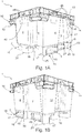
- Figures 1A and 1B show a perspective view of a container 1 according to a preferred embodiment of the invention.
- the container 1 shown is a large plastic load carrier with a pallet-shaped base 2 with recesses or engagement openings 3 for engaging the fork of a forklift truck and four side walls 4, 6, 8, 10.
- the container 1 shown is designed as a nestable container 1, ie the four side walls 4, 6, 8, 10 flare conically towards the container opening in order to enable containers 1 of identical construction to be nested (see, for example, Figure 2A ). More precisely, the container 1 shown is a so-called rotary stacking container, which can either be stacked or nested with an identical container, depending on the relative rotation of the two identical containers to one another.
- the container 1 shown has a projecting container edge 12 which defines its container opening and which is structurally reinforced with a circumferential rib ring.
- the rib structure of the container edge 12 forms recessed areas (not designated here in more detail) which enable one or more containers 1 to be lifted out of a container Allow stacked container 1 by means of a forklift. Especially in such separation operations with forklifts, it is often the case that stacked containers 1 are knocked over.
- the side wall 4 has a side wall recess 5, the side wall 6 has a side wall recess 7, the side wall 8 has side wall recesses 9 and the side wall 10 has a side wall recess 11.
- the bottom 2 has lower outer edges 16, 18, 20 and 22.
- the lower outer edge 16 extends in at a lower end of the side wall 4, the lower outer edge 18 extends in at a lower end of the side wall 6, the lower outer edge 20 extends in at a lower end of the side wall 8 and the lower outer edge 22 in a lower end of the side wall 10.
- the lower outer edge 16 is formed by a runner 17 and the lower outer edge 18 is formed by a runner 19.
- the runner 17 has one skid recess 21 offset inwards.
- the skid 19 has an inwardly offset skid recess 23.
- the two skid recesses 21 and 23 and the two side wall recesses 5 and 7 are each groove-shaped.
- the side wall recesses 5 and 7 extend from the container edge 12 down to the bottom 2.
- the skid recesses 21 and 23 each extend from an upper side of the respective skids 17 and 19 to an underside of the respective skids 17 and 19.
- the side wall recess 5 merges flush into the skid recess 21 so that both together form an inwardly offset, channel-like structure.
- the side wall recess 7 merges flush with the skid recess 23, so that both together form an inwardly offset, channel-shaped structure.
- the skids 17 and 19 each have a curved outer contour.
- the outer edges 16 and 18 are S-shaped due to the skid recesses 5 and 7.
- Respective end sections of the lower outer edges 16 and 18 of the runners 17 and 19, so-called runner outer edge end sections 25 and 27, are designed such that the runner outer edge end sections 25 of the runner 17 extend in a common (imaginary) straight line and that runner outer edge end sections 27 of the runner 19 extend in one extend common (imaginary) straight line.
- the outer edges 16 and 18 of the runners 17 and 19 have S-shaped sections S between the respective skid recess 5 or 7 and the corresponding skid outer edge end sections 25 or 27, more precisely at end regions of the skid recesses 5 or 7.
- the container 1 of the Figures 1A and 1B has in each case in its corner regions horizontally or parallel to the floor projections or ribs 13, which are arranged lower than the circumferential rib rings of the container edge 12 and serve as a stop to limit the depth of the nest when nesting several identical containers 1.
- Support recesses 42 are provided on the top of the container edge 12. Support areas 44 are provided on the underside of the runners 17 and 19. When a structurally identical pallet container is stacked on the pallet container 1, the (lower) contact areas of the runners of the identical pallet container can be immersed in the support recesses 42. Lower surfaces of the support recesses 42 extend in a common plane. Lower surfaces 45 of the engagement openings 3 also extend in a common plane.
- a depth T of the support recesses 42 of the pallet container 1, which extends from the upper side of the container edge 12 to a lower surface of the support recess, is determined such that it is less than or equal to a distance D between the common plane of the lower surface 45 of the engagement openings 3 of the pallet container 1 and the common plane of the lower surfaces of the support areas 44 of the runners 17 and 19 of the pallet container 1.
- two recessed grips 46 are provided on the long side walls 4 and 6 and one recessed grip 46 on the short side walls 8 and 10.
- the recessed grips 46 are oriented such that the recessed grips 46 can be gripped from below.
- each recessed grip 46 is in each case formed by a U-shaped rib of the rib structure of the container edge 12.
- the respective U-shaped rib is oriented so that its opening is directed downwards.
- An outer wall adjoins an edge of the respective U-shaped rib facing away from the interior of the container, which wall, together with the U-shaped rib, encloses the recessed grip 46.
- FIGS. 2A, 2B and 2C illustrate the behavior of a stack of nested large load carriers 1, 1 'when tipping over. It has been determined by the applicant that due to inertia and due to the play between the individual nested containers 1, the lower edge of the projecting container edge 12 'of the bottom container 1' of the stack often forms the first point of impact of such a container stack. This is usually not designed for such loads, which causes the container edge 12 'to break and the container 1' to become unusable.
- Figure 2B shows an end position in which the stack comes to rest on the container edges 12 of the container 1.
- the container edge 12 of the lowermost container 1 of a tipping stack of nested container 1 receives a disproportionately large proportion of the impact force and the exact impact point of impact of the individual containers 1 varies with their position in the container stack. As a result, it is difficult to design the container rim 12 for this load.
- the container 1 according to the preferred embodiment of the invention has a bumper structure or a bumper 14. Like in Figure 2A As can be clearly seen, the bumper 14 'is designed such that it projects beneath the container edge 12' and far enough from the side wall that when a stack of nested containers 1 tips over, the bumper 14 'of the lowest container 1' hits the floor in front of its container edge 12A . The same applies to the containers 1 arranged somewhat further up in the stack.
- the container 1 according to the preferred exemplary embodiment has four such bumpers 14, which are each arranged in corner regions and essentially shield two opposite side walls 4, 6 of the container 1 or from project this (cf. Fig. 1A ).
- the bumper 14 is designed as a bumper structure spaced from the container edge 12 towards the underside of the container and projecting in profile over the side wall 4, 6. More precisely, the bumper protrudes so far from the associated outside of the container that it has an imaginary plane E, which is between the lower outer edge 24, 26, 28, 30 of the projecting container edge 12 and the outer edge 16, 18, 20, 22 of the base 2 and is stretched between the lower outer edge 24, 26 of the projecting container edge 12 and outer runner edge end sections 25, 27 of the base 2.
- the bumper 14 protrudes from the outside of the associated side wall 4, 6, 8, 10 to such an extent that it projects beyond the imaginary plane E and thus when it tilts (with the outer edge 16, 18, 20, 22 of the base 2 as the instantaneous pole) in front of the lower outer edge 24, 26, 28, 30 of the projecting container rim 12 on the floor.
- the bumper 14 is spaced down in the container height direction from the container edge 12 and projects so far in the direction parallel to the floor that it ends flush with a projection A of the outer surface of the container edge 12.
- this serves the purpose that the bumper does not unnecessarily enlarge the external dimensions of the container 1 and, on the other hand, the outer surface of the container edge 12 and the bumper 14 can both serve as support points in a tilted container stack (see also Figure 2C ).
- bumpers 14 A number of preferred exemplary embodiments for bumpers 14 according to the present invention are explained below. All of these embodiments have in common that their overall structure or predetermined impact absorption sections 32 are designed to at least partially absorb or dissipate impacts. Mechanisms for such dissipation of impact energy are mainly internal friction losses in the case of elastic deformation and / or in the plastic deformation of components.
- the bumper 14 shown is designed in its basic structure as a hollow profile and in each case arranged in the corner regions of the container 1.
- Said hollow profile shape includes a cavity or a clear space R between the side wall and the bumper 14.
- the hollow profile-shaped bumper 14 is integrally formed on the container 1 and, due to its overall structure or due to the clear space R enclosed towards the wall, exhibits an elasticity and a defined spring travel / a defined crumple zone for absorbing impact forces.
- the hollow profile shape of the bumper 14 forms a defined butt section 15 at its end (seen from the crimped side wall 4) on the outside of the container, in this case a flattened end section.
- the structure of the bumper 14 (of the hollow profile) widens in the direction towards the container or in the direction towards a container center plane M.
- This has the advantage that impact forces at the impact section 15 can be introduced into the bumper 14 in a defined manner and then distributed over a larger area and introduced into the container 1.
- the expanding hollow profile structure supports a defined elastic deformation of the bumper 14.
- the hollow profile-shaped bumper 14 is molded onto the container 1 in such a way that the hollow profile is open in the direction of the side wall 8, 10 adjacent to the shielded side wall 4, 6. This enables good demoldability during production in a plastic casting process.
- An essentially horizontal or parallel to the floor lower cut of the bumper 14 (or its hollow profile shape) is formed by the rib 13, which also serves to limit the depth of the nest.
- Fig. 5 shows a detailed view of a hollow profile-shaped bumper 14 according to a second embodiment, which is similar in shape and function to the bumper 14 according to the first embodiment.
- the main distinguishing feature of the bumper 14 according to the second embodiment compared to the first embodiment is the rounded or substantially semicircular hollow section section 15 flattened curved butt section 15 according to the embodiment of FIG Figure 4
- the semicircular profile shape creates a higher point of impact in the event of a tipping over and thus an advantageous introduction of force into the hollow profile structure of the bumper 14 which widens in the direction of the container center plane M.
- the bumper 14 shown according to a third exemplary embodiment of the invention has, like the bumper 14 according to the second exemplary embodiment, a round / rounded bumper section 15.
- the bumper 14 has, on the lower half of its semi-circular profile-shaped bumper section 15, a projection 34 which points obliquely away from the interior of the container and points downwards for a defined introduction of force into the bumper 14.
- the semicircular butt section 15 is made above the projection 34 with a reduced material thickness in order to provide a defined predetermined breaking point 35 in this area.
- the bumper 14 according to the in Figure 6 shows a spring section 36 via which it is suspended on the container 1 (here on the container edge 12). Due to the resilient suspension already provided by the spring section 36, the bumper 14 according to the third exemplary embodiment can be designed with a less widening hollow profile structure.
- Fig. 7 shows a fourth embodiment of a bumper 14 according to the invention.
- This has an impact absorption section 38 in the form of a folded section 38. Similar to comparable structures in cars, the folded structure enables a defined deformation with increased energy dissipation per compressed route.
- the folded section 38 is arranged in the horizontally running section or the rib 13 of the hollow-profile-shaped bumper 14 and adjacent to the butt section 15 in order to absorb the impact forces that occur in the event of an impact as directly as possible.
- Fig. 8 shows a fifth preferred embodiment of a bumper 14, which is manufactured in a 2-component injection molding process.
- the butt section 15 of the bumper 14 projecting away from the interior of the container is coated with an elastomer section 40, which absorbs the forces that occur in the event of an impact.
- an elastomer cushion 40 is molded onto the bumper 14 on the outside of the container.
- the impact section 15 thus forms the impact absorption section 32 per se.
Landscapes
- Engineering & Computer Science (AREA)
- Mechanical Engineering (AREA)
- Pallets (AREA)
- Vibration Dampers (AREA)
Priority Applications (2)
| Application Number | Priority Date | Filing Date | Title |
|---|---|---|---|
| PCT/EP2020/051101 WO2020148417A1 (fr) | 2019-01-17 | 2020-01-17 | Récipient à palettes à empilement rotatif |
| US17/423,523 US20220119151A1 (en) | 2019-01-17 | 2020-01-17 | Rotatable, stackable pallet container |
Applications Claiming Priority (1)
| Application Number | Priority Date | Filing Date | Title |
|---|---|---|---|
| EP19152320.8A EP3683163B1 (fr) | 2019-01-17 | 2019-01-17 | Récipient pourvu de pare-chocs |
Publications (2)
| Publication Number | Publication Date |
|---|---|
| EP3683162A1 true EP3683162A1 (fr) | 2020-07-22 |
| EP3683162B1 EP3683162B1 (fr) | 2022-09-07 |
Family
ID=65041579
Family Applications (2)
| Application Number | Title | Priority Date | Filing Date |
|---|---|---|---|
| EP19152320.8A Active EP3683163B1 (fr) | 2019-01-17 | 2019-01-17 | Récipient pourvu de pare-chocs |
| EP19170269.5A Active EP3683162B1 (fr) | 2019-01-17 | 2019-04-18 | Contenant rotatif pour palette de gerbage |
Family Applications Before (1)
| Application Number | Title | Priority Date | Filing Date |
|---|---|---|---|
| EP19152320.8A Active EP3683163B1 (fr) | 2019-01-17 | 2019-01-17 | Récipient pourvu de pare-chocs |
Country Status (3)
| Country | Link |
|---|---|
| US (2) | US20220119151A1 (fr) |
| EP (2) | EP3683163B1 (fr) |
| WO (2) | WO2020148417A1 (fr) |
Cited By (1)
| Publication number | Priority date | Publication date | Assignee | Title |
|---|---|---|---|---|
| US20240417135A1 (en) * | 2021-10-21 | 2024-12-19 | Enpac, Llc | Spill pallet |
Families Citing this family (1)
| Publication number | Priority date | Publication date | Assignee | Title |
|---|---|---|---|---|
| RU206959U1 (ru) * | 2021-04-20 | 2021-10-04 | Общество с ограниченной ответственностью "Ай-Пласт" | Контейнер полимерный с захватами для ротирования |
Citations (5)
| Publication number | Priority date | Publication date | Assignee | Title |
|---|---|---|---|---|
| US4386700A (en) * | 1981-05-28 | 1983-06-07 | Nestier Corporation | Drain control for multiple stacked containers |
| US4416374A (en) * | 1982-04-16 | 1983-11-22 | Pennsylvania Pacific Corporation | Nest and stack container |
| DE20215449U1 (de) * | 2002-10-08 | 2003-01-16 | Bito-Lagertechnik Bittmann GmbH, 55590 Meisenheim | Lagerbehälter |
| WO2007128043A1 (fr) * | 2006-05-02 | 2007-11-15 | Checkmate International Pty Ltd | Conteneurs empilables a fenêtres |
| DE202013100968U1 (de) | 2013-03-06 | 2013-05-03 | Paul Craemer Gmbh | Palettenbox |
Family Cites Families (9)
| Publication number | Priority date | Publication date | Assignee | Title |
|---|---|---|---|---|
| GB1268019A (en) * | 1970-03-24 | 1972-03-22 | Ms Ind Inc | Tote box with bumper |
| US3902599A (en) * | 1970-05-29 | 1975-09-02 | Stromberg & Co As Svein | Transport box for fish or other food |
| SE8003298L (sv) * | 1980-04-30 | 1981-10-31 | Plm Ab | Behallare |
| FR2621297B1 (fr) * | 1987-10-05 | 1990-04-27 | Allibert Sa | Caisse de manutention empilable et emboitable |
| WO2011084954A1 (fr) * | 2010-01-05 | 2011-07-14 | Owens Corning Intellectual Capital, Llc | Emballage de produit restant avec le produit et fonctionnant comme une isolation acoustique et/ou thermique |
| US20120181214A1 (en) * | 2010-07-06 | 2012-07-19 | Kard Reclycling Service, Inc. | Structure and process for recycling containers |
| CN102638954A (zh) * | 2012-04-17 | 2012-08-15 | 青岛科而泰环境控制技术有限公司 | 便携式电器的耐冲击保护壳 |
| US9708097B2 (en) * | 2013-11-15 | 2017-07-18 | Orbis Corporation | Bulk bin with integrated shock absorber |
| EP3395722A1 (fr) * | 2017-04-28 | 2018-10-31 | Reflex Marine Ltd | Conteneur de transport |
-
2019
- 2019-01-17 EP EP19152320.8A patent/EP3683163B1/fr active Active
- 2019-04-18 EP EP19170269.5A patent/EP3683162B1/fr active Active
-
2020
- 2020-01-17 US US17/423,523 patent/US20220119151A1/en not_active Abandoned
- 2020-01-17 US US17/423,541 patent/US20220111998A1/en not_active Abandoned
- 2020-01-17 WO PCT/EP2020/051101 patent/WO2020148417A1/fr not_active Ceased
- 2020-01-17 WO PCT/EP2020/051100 patent/WO2020148416A1/fr not_active Ceased
Patent Citations (5)
| Publication number | Priority date | Publication date | Assignee | Title |
|---|---|---|---|---|
| US4386700A (en) * | 1981-05-28 | 1983-06-07 | Nestier Corporation | Drain control for multiple stacked containers |
| US4416374A (en) * | 1982-04-16 | 1983-11-22 | Pennsylvania Pacific Corporation | Nest and stack container |
| DE20215449U1 (de) * | 2002-10-08 | 2003-01-16 | Bito-Lagertechnik Bittmann GmbH, 55590 Meisenheim | Lagerbehälter |
| WO2007128043A1 (fr) * | 2006-05-02 | 2007-11-15 | Checkmate International Pty Ltd | Conteneurs empilables a fenêtres |
| DE202013100968U1 (de) | 2013-03-06 | 2013-05-03 | Paul Craemer Gmbh | Palettenbox |
Cited By (2)
| Publication number | Priority date | Publication date | Assignee | Title |
|---|---|---|---|---|
| US20240417135A1 (en) * | 2021-10-21 | 2024-12-19 | Enpac, Llc | Spill pallet |
| US12545473B2 (en) * | 2021-10-21 | 2026-02-10 | Enpac, L.L.C. | Spill pallet |
Also Published As
| Publication number | Publication date |
|---|---|
| WO2020148416A1 (fr) | 2020-07-23 |
| EP3683163B1 (fr) | 2022-08-10 |
| US20220119151A1 (en) | 2022-04-21 |
| EP3683162B1 (fr) | 2022-09-07 |
| EP3683163A1 (fr) | 2020-07-22 |
| US20220111998A1 (en) | 2022-04-14 |
| WO2020148417A1 (fr) | 2020-07-23 |
Similar Documents
| Publication | Publication Date | Title |
|---|---|---|
| DE60101556T2 (de) | Durch umlaufende nuten verstärkter kunststoffbehälter mit nicht-zylindrischem körper | |
| EP1131249B1 (fr) | Conteneur constitue de plusieurs plaques | |
| CH422633A (de) | Satz von Lager- und Transportbehältern | |
| EP3683162B1 (fr) | Contenant rotatif pour palette de gerbage | |
| DE9206973U1 (de) | Lager- und Transportbehälter aus Kunststoff | |
| EP2794410B1 (fr) | Bidon empilable | |
| DE2549400C3 (de) | Kunststoffbehälter | |
| DE3517089C2 (de) | Behälter, insbesondere Drehstapelbehälter | |
| EP0818394B1 (fr) | Récipient en plastique empilable par rotation | |
| EP0231008B1 (fr) | Caisse empilable en plastique | |
| DE19614530A1 (de) | Zusammenklappbarer Transportbehälter | |
| DE202010001637U1 (de) | Behälterfuß | |
| EP0572946B1 (fr) | Palette en matière synthétique | |
| DE2714623C3 (de) | Stapelbare Steige | |
| CH686360A5 (de) | Lager- und Transportbehaelter aus Kunststoff. | |
| DE102018127668A1 (de) | Lagerelement sowie Verfahren zum Betreiben eines daraus aufgebauten Lagers | |
| EP3543158B1 (fr) | Conteneur de transport | |
| DE102004016976B4 (de) | Lagerbox | |
| DE3934800A1 (de) | Stapeltransportkasten aus metallischem schichtmaterial | |
| EP4192751B1 (fr) | Récipient en matière plastique | |
| EP2987742B1 (fr) | Recipient empilable ayant une structure de transfert de charge | |
| DE202013100968U1 (de) | Palettenbox | |
| DE8817083U1 (de) | Stapelbarer Flaschenkasten aus Kunststoff | |
| DE1141582B (de) | Behaelter mit Boden und Deckel | |
| DE10314111B4 (de) | Ladeeinheit mit Palettiertablar |
Legal Events
| Date | Code | Title | Description |
|---|---|---|---|
| PUAI | Public reference made under article 153(3) epc to a published international application that has entered the european phase |
Free format text: ORIGINAL CODE: 0009012 |
|
| STAA | Information on the status of an ep patent application or granted ep patent |
Free format text: STATUS: THE APPLICATION HAS BEEN PUBLISHED |
|
| AK | Designated contracting states |
Kind code of ref document: A1 Designated state(s): AL AT BE BG CH CY CZ DE DK EE ES FI FR GB GR HR HU IE IS IT LI LT LU LV MC MK MT NL NO PL PT RO RS SE SI SK SM TR |
|
| AX | Request for extension of the european patent |
Extension state: BA ME |
|
| STAA | Information on the status of an ep patent application or granted ep patent |
Free format text: STATUS: REQUEST FOR EXAMINATION WAS MADE |
|
| 17P | Request for examination filed |
Effective date: 20210122 |
|
| RBV | Designated contracting states (corrected) |
Designated state(s): AL AT BE BG CH CY CZ DE DK EE ES FI FR GB GR HR HU IE IS IT LI LT LU LV MC MK MT NL NO PL PT RO RS SE SI SK SM TR |
|
| GRAP | Despatch of communication of intention to grant a patent |
Free format text: ORIGINAL CODE: EPIDOSNIGR1 |
|
| STAA | Information on the status of an ep patent application or granted ep patent |
Free format text: STATUS: GRANT OF PATENT IS INTENDED |
|
| INTG | Intention to grant announced |
Effective date: 20220404 |
|
| GRAS | Grant fee paid |
Free format text: ORIGINAL CODE: EPIDOSNIGR3 |
|
| GRAA | (expected) grant |
Free format text: ORIGINAL CODE: 0009210 |
|
| STAA | Information on the status of an ep patent application or granted ep patent |
Free format text: STATUS: THE PATENT HAS BEEN GRANTED |
|
| RAP3 | Party data changed (applicant data changed or rights of an application transferred) |
Owner name: SCHOELLER ALLIBERT GMBH |
|
| AK | Designated contracting states |
Kind code of ref document: B1 Designated state(s): AL AT BE BG CH CY CZ DE DK EE ES FI FR GB GR HR HU IE IS IT LI LT LU LV MC MK MT NL NO PL PT RO RS SE SI SK SM TR |
|
| REG | Reference to a national code |
Ref country code: GB Ref legal event code: FG4D Free format text: NOT ENGLISH |
|
| REG | Reference to a national code |
Ref country code: CH Ref legal event code: EP Ref country code: AT Ref legal event code: REF Ref document number: 1516884 Country of ref document: AT Kind code of ref document: T Effective date: 20220915 |
|
| REG | Reference to a national code |
Ref country code: DE Ref legal event code: R096 Ref document number: 502019005531 Country of ref document: DE |
|
| REG | Reference to a national code |
Ref country code: IE Ref legal event code: FG4D Free format text: LANGUAGE OF EP DOCUMENT: GERMAN |
|
| REG | Reference to a national code |
Ref country code: NL Ref legal event code: FP |
|
| REG | Reference to a national code |
Ref country code: LT Ref legal event code: MG9D |
|
| PG25 | Lapsed in a contracting state [announced via postgrant information from national office to epo] |
Ref country code: SE Free format text: LAPSE BECAUSE OF FAILURE TO SUBMIT A TRANSLATION OF THE DESCRIPTION OR TO PAY THE FEE WITHIN THE PRESCRIBED TIME-LIMIT Effective date: 20220907 Ref country code: RS Free format text: LAPSE BECAUSE OF FAILURE TO SUBMIT A TRANSLATION OF THE DESCRIPTION OR TO PAY THE FEE WITHIN THE PRESCRIBED TIME-LIMIT Effective date: 20220907 Ref country code: NO Free format text: LAPSE BECAUSE OF FAILURE TO SUBMIT A TRANSLATION OF THE DESCRIPTION OR TO PAY THE FEE WITHIN THE PRESCRIBED TIME-LIMIT Effective date: 20221207 Ref country code: LV Free format text: LAPSE BECAUSE OF FAILURE TO SUBMIT A TRANSLATION OF THE DESCRIPTION OR TO PAY THE FEE WITHIN THE PRESCRIBED TIME-LIMIT Effective date: 20220907 Ref country code: LT Free format text: LAPSE BECAUSE OF FAILURE TO SUBMIT A TRANSLATION OF THE DESCRIPTION OR TO PAY THE FEE WITHIN THE PRESCRIBED TIME-LIMIT Effective date: 20220907 Ref country code: FI Free format text: LAPSE BECAUSE OF FAILURE TO SUBMIT A TRANSLATION OF THE DESCRIPTION OR TO PAY THE FEE WITHIN THE PRESCRIBED TIME-LIMIT Effective date: 20220907 |
|
| PG25 | Lapsed in a contracting state [announced via postgrant information from national office to epo] |
Ref country code: HR Free format text: LAPSE BECAUSE OF FAILURE TO SUBMIT A TRANSLATION OF THE DESCRIPTION OR TO PAY THE FEE WITHIN THE PRESCRIBED TIME-LIMIT Effective date: 20220907 Ref country code: GR Free format text: LAPSE BECAUSE OF FAILURE TO SUBMIT A TRANSLATION OF THE DESCRIPTION OR TO PAY THE FEE WITHIN THE PRESCRIBED TIME-LIMIT Effective date: 20221208 |
|
| PG25 | Lapsed in a contracting state [announced via postgrant information from national office to epo] |
Ref country code: SM Free format text: LAPSE BECAUSE OF FAILURE TO SUBMIT A TRANSLATION OF THE DESCRIPTION OR TO PAY THE FEE WITHIN THE PRESCRIBED TIME-LIMIT Effective date: 20220907 Ref country code: RO Free format text: LAPSE BECAUSE OF FAILURE TO SUBMIT A TRANSLATION OF THE DESCRIPTION OR TO PAY THE FEE WITHIN THE PRESCRIBED TIME-LIMIT Effective date: 20220907 Ref country code: PT Free format text: LAPSE BECAUSE OF FAILURE TO SUBMIT A TRANSLATION OF THE DESCRIPTION OR TO PAY THE FEE WITHIN THE PRESCRIBED TIME-LIMIT Effective date: 20230109 Ref country code: ES Free format text: LAPSE BECAUSE OF FAILURE TO SUBMIT A TRANSLATION OF THE DESCRIPTION OR TO PAY THE FEE WITHIN THE PRESCRIBED TIME-LIMIT Effective date: 20220907 Ref country code: CZ Free format text: LAPSE BECAUSE OF FAILURE TO SUBMIT A TRANSLATION OF THE DESCRIPTION OR TO PAY THE FEE WITHIN THE PRESCRIBED TIME-LIMIT Effective date: 20220907 |
|
| PG25 | Lapsed in a contracting state [announced via postgrant information from national office to epo] |
Ref country code: SK Free format text: LAPSE BECAUSE OF FAILURE TO SUBMIT A TRANSLATION OF THE DESCRIPTION OR TO PAY THE FEE WITHIN THE PRESCRIBED TIME-LIMIT Effective date: 20220907 Ref country code: PL Free format text: LAPSE BECAUSE OF FAILURE TO SUBMIT A TRANSLATION OF THE DESCRIPTION OR TO PAY THE FEE WITHIN THE PRESCRIBED TIME-LIMIT Effective date: 20220907 Ref country code: IS Free format text: LAPSE BECAUSE OF FAILURE TO SUBMIT A TRANSLATION OF THE DESCRIPTION OR TO PAY THE FEE WITHIN THE PRESCRIBED TIME-LIMIT Effective date: 20230107 Ref country code: EE Free format text: LAPSE BECAUSE OF FAILURE TO SUBMIT A TRANSLATION OF THE DESCRIPTION OR TO PAY THE FEE WITHIN THE PRESCRIBED TIME-LIMIT Effective date: 20220907 |
|
| REG | Reference to a national code |
Ref country code: DE Ref legal event code: R097 Ref document number: 502019005531 Country of ref document: DE |
|
| PG25 | Lapsed in a contracting state [announced via postgrant information from national office to epo] |
Ref country code: AL Free format text: LAPSE BECAUSE OF FAILURE TO SUBMIT A TRANSLATION OF THE DESCRIPTION OR TO PAY THE FEE WITHIN THE PRESCRIBED TIME-LIMIT Effective date: 20220907 |
|
| PLBE | No opposition filed within time limit |
Free format text: ORIGINAL CODE: 0009261 |
|
| STAA | Information on the status of an ep patent application or granted ep patent |
Free format text: STATUS: NO OPPOSITION FILED WITHIN TIME LIMIT |
|
| PG25 | Lapsed in a contracting state [announced via postgrant information from national office to epo] |
Ref country code: DK Free format text: LAPSE BECAUSE OF FAILURE TO SUBMIT A TRANSLATION OF THE DESCRIPTION OR TO PAY THE FEE WITHIN THE PRESCRIBED TIME-LIMIT Effective date: 20220907 |
|
| 26N | No opposition filed |
Effective date: 20230608 |
|
| PG25 | Lapsed in a contracting state [announced via postgrant information from national office to epo] |
Ref country code: SI Free format text: LAPSE BECAUSE OF FAILURE TO SUBMIT A TRANSLATION OF THE DESCRIPTION OR TO PAY THE FEE WITHIN THE PRESCRIBED TIME-LIMIT Effective date: 20220907 |
|
| REG | Reference to a national code |
Ref country code: DE Ref legal event code: R119 Ref document number: 502019005531 Country of ref document: DE |
|
| REG | Reference to a national code |
Ref country code: CH Ref legal event code: PL |
|
| GBPC | Gb: european patent ceased through non-payment of renewal fee |
Effective date: 20230418 |
|
| PG25 | Lapsed in a contracting state [announced via postgrant information from national office to epo] |
Ref country code: LU Free format text: LAPSE BECAUSE OF NON-PAYMENT OF DUE FEES Effective date: 20230418 |
|
| PG25 | Lapsed in a contracting state [announced via postgrant information from national office to epo] |
Ref country code: MC Free format text: LAPSE BECAUSE OF FAILURE TO SUBMIT A TRANSLATION OF THE DESCRIPTION OR TO PAY THE FEE WITHIN THE PRESCRIBED TIME-LIMIT Effective date: 20220907 |
|
| PG25 | Lapsed in a contracting state [announced via postgrant information from national office to epo] |
Ref country code: GB Free format text: LAPSE BECAUSE OF NON-PAYMENT OF DUE FEES Effective date: 20230418 |
|
| PG25 | Lapsed in a contracting state [announced via postgrant information from national office to epo] |
Ref country code: MC Free format text: LAPSE BECAUSE OF FAILURE TO SUBMIT A TRANSLATION OF THE DESCRIPTION OR TO PAY THE FEE WITHIN THE PRESCRIBED TIME-LIMIT Effective date: 20220907 Ref country code: LI Free format text: LAPSE BECAUSE OF NON-PAYMENT OF DUE FEES Effective date: 20230430 Ref country code: GB Free format text: LAPSE BECAUSE OF NON-PAYMENT OF DUE FEES Effective date: 20230418 Ref country code: DE Free format text: LAPSE BECAUSE OF NON-PAYMENT OF DUE FEES Effective date: 20231103 Ref country code: CH Free format text: LAPSE BECAUSE OF NON-PAYMENT OF DUE FEES Effective date: 20230430 |
|
| REG | Reference to a national code |
Ref country code: IE Ref legal event code: MM4A |
|
| PG25 | Lapsed in a contracting state [announced via postgrant information from national office to epo] |
Ref country code: IE Free format text: LAPSE BECAUSE OF NON-PAYMENT OF DUE FEES Effective date: 20230418 |
|
| PG25 | Lapsed in a contracting state [announced via postgrant information from national office to epo] |
Ref country code: IE Free format text: LAPSE BECAUSE OF NON-PAYMENT OF DUE FEES Effective date: 20230418 |
|
| PG25 | Lapsed in a contracting state [announced via postgrant information from national office to epo] |
Ref country code: IT Free format text: LAPSE BECAUSE OF FAILURE TO SUBMIT A TRANSLATION OF THE DESCRIPTION OR TO PAY THE FEE WITHIN THE PRESCRIBED TIME-LIMIT Effective date: 20220907 |
|
| PG25 | Lapsed in a contracting state [announced via postgrant information from national office to epo] |
Ref country code: BG Free format text: LAPSE BECAUSE OF FAILURE TO SUBMIT A TRANSLATION OF THE DESCRIPTION OR TO PAY THE FEE WITHIN THE PRESCRIBED TIME-LIMIT Effective date: 20220907 |
|
| PG25 | Lapsed in a contracting state [announced via postgrant information from national office to epo] |
Ref country code: BG Free format text: LAPSE BECAUSE OF FAILURE TO SUBMIT A TRANSLATION OF THE DESCRIPTION OR TO PAY THE FEE WITHIN THE PRESCRIBED TIME-LIMIT Effective date: 20220907 |
|
| PGFP | Annual fee paid to national office [announced via postgrant information from national office to epo] |
Ref country code: NL Payment date: 20250422 Year of fee payment: 7 |
|
| REG | Reference to a national code |
Ref country code: AT Ref legal event code: MM01 Ref document number: 1516884 Country of ref document: AT Kind code of ref document: T Effective date: 20240418 |
|
| PGFP | Annual fee paid to national office [announced via postgrant information from national office to epo] |
Ref country code: BE Payment date: 20250422 Year of fee payment: 7 |
|
| PGFP | Annual fee paid to national office [announced via postgrant information from national office to epo] |
Ref country code: FR Payment date: 20250422 Year of fee payment: 7 |
|
| PG25 | Lapsed in a contracting state [announced via postgrant information from national office to epo] |
Ref country code: AT Free format text: LAPSE BECAUSE OF NON-PAYMENT OF DUE FEES Effective date: 20240418 |
|
| PG25 | Lapsed in a contracting state [announced via postgrant information from national office to epo] |
Ref country code: CY Free format text: LAPSE BECAUSE OF FAILURE TO SUBMIT A TRANSLATION OF THE DESCRIPTION OR TO PAY THE FEE WITHIN THE PRESCRIBED TIME-LIMIT; INVALID AB INITIO Effective date: 20190418 |
|
| PG25 | Lapsed in a contracting state [announced via postgrant information from national office to epo] |
Ref country code: HU Free format text: LAPSE BECAUSE OF FAILURE TO SUBMIT A TRANSLATION OF THE DESCRIPTION OR TO PAY THE FEE WITHIN THE PRESCRIBED TIME-LIMIT; INVALID AB INITIO Effective date: 20190418 |
|
| PG25 | Lapsed in a contracting state [announced via postgrant information from national office to epo] |
Ref country code: TR Free format text: LAPSE BECAUSE OF FAILURE TO SUBMIT A TRANSLATION OF THE DESCRIPTION OR TO PAY THE FEE WITHIN THE PRESCRIBED TIME-LIMIT Effective date: 20220907 |
|
| PGFP | Annual fee paid to national office [announced via postgrant information from national office to epo] |
Ref country code: AT Payment date: 20260410 Year of fee payment: 5 |