EP3683169B1 - Procédé d'assemblage d'un système de distribution pour distribuer un milieu fluide - Google Patents
Procédé d'assemblage d'un système de distribution pour distribuer un milieu fluide Download PDFInfo
- Publication number
- EP3683169B1 EP3683169B1 EP20159201.1A EP20159201A EP3683169B1 EP 3683169 B1 EP3683169 B1 EP 3683169B1 EP 20159201 A EP20159201 A EP 20159201A EP 3683169 B1 EP3683169 B1 EP 3683169B1
- Authority
- EP
- European Patent Office
- Prior art keywords
- container
- valve cup
- valve
- bag
- polyester
- Prior art date
- Legal status (The legal status is an assumption and is not a legal conclusion. Google has not performed a legal analysis and makes no representation as to the accuracy of the status listed.)
- Active
Links
Images


Classifications
-
- B—PERFORMING OPERATIONS; TRANSPORTING
- B65—CONVEYING; PACKING; STORING; HANDLING THIN OR FILAMENTARY MATERIAL
- B65B—MACHINES, APPARATUS OR DEVICES FOR, OR METHODS OF, PACKAGING ARTICLES OR MATERIALS; UNPACKING
- B65B31/00—Packaging articles or materials under special atmospheric or gaseous conditions; Adding propellants to aerosol containers
- B65B31/02—Filling, closing, or filling and closing, containers or wrappers in chambers maintained under vacuum or superatmospheric pressure or containing a special atmosphere, e.g. of inert gas
- B65B31/025—Filling, closing, or filling and closing, containers or wrappers in chambers maintained under vacuum or superatmospheric pressure or containing a special atmosphere, e.g. of inert gas specially adapted for rigid or semi-rigid containers
- B65B31/028—Filling, closing, or filling and closing, containers or wrappers in chambers maintained under vacuum or superatmospheric pressure or containing a special atmosphere, e.g. of inert gas specially adapted for rigid or semi-rigid containers closed by a lid sealed to the upper rim of the container, e.g. tray-like container
-
- B—PERFORMING OPERATIONS; TRANSPORTING
- B65—CONVEYING; PACKING; STORING; HANDLING THIN OR FILAMENTARY MATERIAL
- B65D—CONTAINERS FOR STORAGE OR TRANSPORT OF ARTICLES OR MATERIALS, e.g. BAGS, BARRELS, BOTTLES, BOXES, CANS, CARTONS, CRATES, DRUMS, JARS, TANKS, HOPPERS, FORWARDING CONTAINERS; ACCESSORIES, CLOSURES, OR FITTINGS THEREFOR; PACKAGING ELEMENTS; PACKAGES
- B65D83/00—Containers or packages with special means for dispensing contents
- B65D83/14—Containers for dispensing liquid or semi-liquid contents by internal gaseous pressure, i.e. aerosol containers comprising propellant
- B65D83/60—Containers for dispensing liquid or semi-liquid contents by internal gaseous pressure, i.e. aerosol containers comprising propellant with contents and propellant separated
- B65D83/62—Containers for dispensing liquid or semi-liquid contents by internal gaseous pressure, i.e. aerosol containers comprising propellant with contents and propellant separated by membranes, bags or the like
-
- B—PERFORMING OPERATIONS; TRANSPORTING
- B65—CONVEYING; PACKING; STORING; HANDLING THIN OR FILAMENTARY MATERIAL
- B65B—MACHINES, APPARATUS OR DEVICES FOR, OR METHODS OF, PACKAGING ARTICLES OR MATERIALS; UNPACKING
- B65B31/00—Packaging articles or materials under special atmospheric or gaseous conditions; Adding propellants to aerosol containers
- B65B31/003—Adding propellants in fluid form to aerosol containers
-
- B—PERFORMING OPERATIONS; TRANSPORTING
- B65—CONVEYING; PACKING; STORING; HANDLING THIN OR FILAMENTARY MATERIAL
- B65D—CONTAINERS FOR STORAGE OR TRANSPORT OF ARTICLES OR MATERIALS, e.g. BAGS, BARRELS, BOTTLES, BOXES, CANS, CARTONS, CRATES, DRUMS, JARS, TANKS, HOPPERS, FORWARDING CONTAINERS; ACCESSORIES, CLOSURES, OR FITTINGS THEREFOR; PACKAGING ELEMENTS; PACKAGES
- B65D83/00—Containers or packages with special means for dispensing contents
- B65D83/14—Containers for dispensing liquid or semi-liquid contents by internal gaseous pressure, i.e. aerosol containers comprising propellant
- B65D83/38—Details of the container body
-
- B—PERFORMING OPERATIONS; TRANSPORTING
- B65—CONVEYING; PACKING; STORING; HANDLING THIN OR FILAMENTARY MATERIAL
- B65D—CONTAINERS FOR STORAGE OR TRANSPORT OF ARTICLES OR MATERIALS, e.g. BAGS, BARRELS, BOTTLES, BOXES, CANS, CARTONS, CRATES, DRUMS, JARS, TANKS, HOPPERS, FORWARDING CONTAINERS; ACCESSORIES, CLOSURES, OR FITTINGS THEREFOR; PACKAGING ELEMENTS; PACKAGES
- B65D83/00—Containers or packages with special means for dispensing contents
- B65D83/14—Containers for dispensing liquid or semi-liquid contents by internal gaseous pressure, i.e. aerosol containers comprising propellant
- B65D83/42—Filling or charging means
- B65D83/425—Delivery valves permitting filling or charging
-
- B—PERFORMING OPERATIONS; TRANSPORTING
- B65—CONVEYING; PACKING; STORING; HANDLING THIN OR FILAMENTARY MATERIAL
- B65D—CONTAINERS FOR STORAGE OR TRANSPORT OF ARTICLES OR MATERIALS, e.g. BAGS, BARRELS, BOTTLES, BOXES, CANS, CARTONS, CRATES, DRUMS, JARS, TANKS, HOPPERS, FORWARDING CONTAINERS; ACCESSORIES, CLOSURES, OR FITTINGS THEREFOR; PACKAGING ELEMENTS; PACKAGES
- B65D83/00—Containers or packages with special means for dispensing contents
- B65D83/14—Containers for dispensing liquid or semi-liquid contents by internal gaseous pressure, i.e. aerosol containers comprising propellant
- B65D83/44—Valves specially adapted for the discharge of contents; Regulating devices
- B65D83/48—Lift valves, e.g. operated by push action
-
- B—PERFORMING OPERATIONS; TRANSPORTING
- B65—CONVEYING; PACKING; STORING; HANDLING THIN OR FILAMENTARY MATERIAL
- B65B—MACHINES, APPARATUS OR DEVICES FOR, OR METHODS OF, PACKAGING ARTICLES OR MATERIALS; UNPACKING
- B65B7/00—Closing containers or receptacles after filling
- B65B7/16—Closing semi-rigid or rigid containers or receptacles not deformed by, or not taking-up shape of, contents, e.g. boxes or cartons
- B65B7/28—Closing semi-rigid or rigid containers or receptacles not deformed by, or not taking-up shape of, contents, e.g. boxes or cartons by applying separate preformed closures, e.g. lids, covers
- B65B7/2842—Securing closures on containers
- B65B7/2878—Securing closures on containers by heat-sealing
-
- B—PERFORMING OPERATIONS; TRANSPORTING
- B65—CONVEYING; PACKING; STORING; HANDLING THIN OR FILAMENTARY MATERIAL
- B65D—CONTAINERS FOR STORAGE OR TRANSPORT OF ARTICLES OR MATERIALS, e.g. BAGS, BARRELS, BOTTLES, BOXES, CANS, CARTONS, CRATES, DRUMS, JARS, TANKS, HOPPERS, FORWARDING CONTAINERS; ACCESSORIES, CLOSURES, OR FITTINGS THEREFOR; PACKAGING ELEMENTS; PACKAGES
- B65D83/00—Containers or packages with special means for dispensing contents
- B65D83/14—Containers for dispensing liquid or semi-liquid contents by internal gaseous pressure, i.e. aerosol containers comprising propellant
- B65D83/16—Actuating means
- B65D83/20—Actuator caps
Definitions
- the invention relates to a method for assembling a dispensing system for dispensing a fluid medium stored under pressure, the dispensing system exhibiting an improvement in sealing performance and attachment between a valve cup and a container.
- Typical systems include a container, a valve, and a valve cup, wherein the valve cup supports the valve usually at a central part thereof and also closes off an opening of the container.
- the inner volume of the container is usually pressurised and maintained in such a state by the valve and the seals between the valve cup and valve, and valve cup and container opening.
- the valve When the valve is actuated, the pressure difference between the inner volume of the container and the outside environment causes the fluid medium to be expelled from the container.
- Some systems employ a two-stage container having an inner and outer container, one of which contains the propellant gas, whereas others may employ a single container with the fluid medium also acting as the propellant.
- the containers are made from a metal, usually aluminium. Recently, there has been an increasing trend to use plastics, namely polyethylene terephthalate (PET), as the containers for these dispensing systems for various advantages such as cost and ease of manufacturing, among others.
- PET polyethylene terephthalate
- the systems should be stable and be able to withstand the internal pressures of the container while also providing an adequate seal.
- Conventional systems employing PET containers also typically use a metal, e.g., aluminium, for the valve cups which ensures a suitable sealing engagement between the valve cup and valve.
- the valve cup may be clinched to a lip of the opening of the container.
- US 2014/0209633 A1 discloses an aerosol dispenser having a pressurized outer container, wherein the lower portion of the neck, and optionally the shoulder of the container, are thermally crystallized in order to improve the strain resistance or product absorption and thereby reduce crazing.
- a valve cup with a polymer lining is not disclosed.
- WO 2009/006137 A1 relates to metered dose inhalers for pharmaceutical aerosols and discloses an aerosol canister employing a polymeric film having improved moisture barrier properties.
- the connection between the canister and a ferrule is realized via a crimp contact area. Welding is not described.
- valve cup can be welded, e.g., friction welded, to the container because the valve cup and container are made of the same or similar materials. At high temperatures, the weld is sufficient to maintain the seal between the valve cup and the container.
- the problem is solved by a method for assembling a dispensing system for dispensing a fluid medium stored under pressure, the method including:
- a bag is attached to a valve which forms part of a valve cup.
- the valve cup and bag are subsequently inserted in the container and positioned adjacent to the opening of the container.
- the inner volume of the container may be pressurised using a propellant gas, preferably by undercup gassing. That is, the volume between the bag and container may be pressurised.
- Assembling the dispensing system in this way allows for the pressurised container to be attached to the valve cup in a state ready to receive a fluid medium.
- the pressures may typically be lower than as used in conventional containers.
- valve cup and the container may be formed from plastic
- plastic welding can be used to join the two, thereby providing a seal between the valve cup and the container.
- This seal is particularly advantageous when deformation of the valve cup and/or container occurs due to exposure to temperatures greater than 50°C because the weld, and thus seal, is maintained.
- the first plastic material is a semi-crystalline polyester.
- the valve cup is a component that supports the valve and is placed so as to cover the opening of a container suitable for containing a fluid medium to be dispensed.
- Semi-crystalline polyesters have a greater degree of crystallinity compared to more amorphous polyesters. As a result, semi-crystalline polyesters typically do not deform when exposed to temperatures greater than 50°C, at least as compared with amorphous polyesters. In this way, structural rigidity of the valve cup can be improved at higher temperatures meaning that the seal between the valve held by the valve cup and the valve cup is maintained.
- a further embodiment of any of the methods above includes the first plastic material having a degree of crystallinity greater than 35%, preferably greater than 38%, when measured using differential scanning calorimetry.
- the degree of crystallinity is one property that provides the plastic material with its rigidity at higher temperatures.
- plastics may have some percentage of amorphous regions and some percentage of crystallised regions. When exposed to high temperatures, the amorphous regions undergo a transition from a hard and brittle state to a more rubbery and soft state. Thus, it can be considered that the amorphous regions lead to deformation of the plastic at greater temperatures. Providing a material with a higher degree of crystallinity may reduce the degree of deformation of the plastic material at higher temperatures.
- the degree of crystallinity is generally measured with respect to a certain method - here it is given as differential scanning calorimetry (DSC).
- DSC differential scanning calorimetry
- various methods may give slightly different results because the degree of crystallinity is essentially an average value.
- an appropriate scaling should be taken into consideration with respect to the value obtained by DSC.
- the first plastic material is selected from the group consisting of: crystallised PET, PBT, PEN, PEN/PET copolymers, or a blend of any of the foregoing; and the second plastic material is a polyester, preferably PET.
- Crystallised PET (CPET), PBT, PEN, and PEN/PET copolymers are or can be semi-crystalline polyesters. These materials are particularly advantageous for their other properties in packaging and not just the rigidity at elevated temperatures. However, any polyester that can be semi-crystalline and does not deform to a suitable degree at large temperatures may also be used as the semi-crystalline material. Moreover, any blend of CPET, PBT, PEN, and PEN/PET may be used as the first plastic material. In a preferred embodiment, PBT is used as the first plastic material.
- Forming the container from a second plastic, such as PET can be highly beneficial.
- the container can retain the advantages of PET as used in packaging, while also being able to be coupled/welded to the valve cup formed of the first plastic. This means that the seal between the valve cup and container can be maintained, even if the container deforms.
- the container is entirely formed from the second plastic material. Forming the container in this way means that the container retains the beneficial properties of the second plastic.
- Polyesters, and in particular PET have many advantageous qualities in packaging applications. They can be easy to manipulate and thus forming valve cups and containers may be relatively easier and quicker. In some cases, the polyesters may also be relatively cheap. Some polyesters can also be recycled thus reducing the overall overhead cost. Finally, some polyesters can also be sterilised which is particularly advantageous for medical applications.
- the second plastic material is a semi-crystalline polyester.
- At least a part of the container may be formed from the semi-crystalline material.
- this part is adjacent or in contact with the opening of the container.
- This part may be a lip portion, a neck portion, and/or the entire container. In this way, when the container experiences elevated temperatures, the part adjacent or in contact with the opening does not deform. In other words, at elevated temperatures, the opening maintains its shape. In this way, any seal with the valve cup can be maintained.
- a further embodiment of the methods above provides the container made from the second plastic material has a degree of crystallinity greater than 35%, preferably greater than 38%, when measured using differential scanning calorimetry.
- Another embodiment of the methods above has the second plastic material selected from the group consisting of: crystallised PET, PBT, PEN, PEN/PET copolymers, or a blend of any of the foregoing; and the first plastic material is a polyester, preferably PET.
- the second plastic material is PBT.
- Plastic valve cups may be advantageous for various reasons such as cost and ease of manufacturing. However, some plastic valve cups may be prone to deformation at higher temperatures. Using a plastic valve cup permits welding to the plastic container. Therefore, even if the valve cup deforms, the container is fixed to the valve cup in such a way that the seal therebetween is not broken. In other words, the seal between the valve cup and container is maintained.
- the rigid part of the container may provide a sufficient rigid basis for any deformation of the valve cup to be directed radially towards the valve supported by the valve cup.
- the radial forces acting against the rigid part of the container may cause a compressive force on a part of the valve at the centre of the valve cup. This means that the valve may be reliably held and sealed by the valve cup even if the valve cup is formed of a deformable plastic.
- the valve cup is formed from a metal or rigid material, and the valve cup includes the polyester lining provided at at least a portion of the valve cup that faces the container when assembled, wherein the polyester lining is either held by the valve cup or is coated onto the valve cup.
- the valve cup may be formed of two materials; a metal or rigid material body, and a polyester lining.
- the metal or rigid material may be formed from any suitable material that does not deform or warp at temperatures greater than 50°C. That is, the rigidity of the valve cup is provided by the metal or rigid material, which thereby ensures that the valve is reliably held and sealed by the valve cup.
- the polyester lining preferably covers at least a part of the metal or rigid material valve cup. Preferably, this part faces the container when the valve cup is fixed to the container. In this way, the valve cup may be welded to a plastic container, thus enabling a seal between the valve cup and the container.
- the polyester lining is coated or held by the valve cup and may be fixed by adhesive to the valve cup.
- the polyester lining may be coated directly onto a surface of the valve cup, thus providing a chemical bond between the metal or rigid material and the polyester lining. This may be advantageous should the polyester lining experience distortion when heated.
- the polyester lining may be held by a specific configuration of the valve cup, e.g., the valve cup may be shaped so as to be able to crimp or clinch the polyester lining. This provides a mechanical configuration which may be advantageous when coating is not possible because of the materials chosen, or when the chemical bonds do not sufficiently withstand deformation of the polyester lining.
- the polyester lining may be provided on an underside of the valve cup.
- the polyester lining may also be formed from any of the semi-crystalline polyesters.
- welding the valve cup to the container includes welding the valve cup to the container by any one of: friction welding, ultrasonic welding, and laser welding.
- These welding techniques are particularly advantageous as they can be used to weld plastic to plastic, and do not cause any propellant gas to adversely react, e.g., these techniques do not provide a source of ignition.
- Another embodiment of any of the methods involves pressurising the volume of the container between the inside of the container and the outside of the bag to between 1 to 3 bar, preferably between 1 .5 to 2.5 bar, by undercup gassing.
- the pressurisation is performed without any fluid medium to be dispensed disposed in the bag.
- any addition of the fluid medium to the dispensing system via the valve thereof increases the pressure within the container. This may then provide the necessary pressure for dispensing the fluid medium. Performing the pressurisation in this way means that the welding process is substantially easier because the pressures involved are lower.
- a further embodiment of any of the methods above involves the valve cup including an inverted U-shaped receiving portion and the container including a lip portion, wherein prior to welding the valve cup to the container, the method further includes snap fitting the inverted U-shaped receiving portion to the lip portion.
- the inverted U-shaped receiving portion can be provided on an outer surface or diameter of the valve cup and is preferably shaped and sized to receive a lip portion of the container. In this manner, the valve cup can be reliably positioned with respect to the container and can be suitably attached via, for example, welding.
- the inverted U-shaped receiving portion may be provided with at least one protrusion to aid in fixing, at least temporarily, the valve cup to the container to thereby facilitate the welding without concern of the valve cup being displaced.
- Another embodiment of the method above further comprises, before inserting the bag into the container, folding the bag so as to decrease the footprint of the bag to less than the diameter of the opening of the container.
- the folding includes twisting the bag around a central axis of the valve or folding the bag into a concertina pattern.
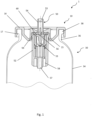
- Fig. 1 shows a dispensing system 1.
- the dispensing system 1 includes a valve cup 10 according to a first example that may be used with the method according to the invention, a container 30, and a valve 50.
- the inner region of the container 30 is pressurised to a pressure greater than atmospheric pressure.
- this pressure may be 7 bar, although the pressure is not limited to this and may take any desired value limited only by regional or governmental restrictions.
- the valve 50 is generally held in a fixed position by the valve cup 10 such that, when a force is applied to the valve 50 from a user, the valve 50 can be actuated to an open position. In this position, the pressure difference causes the fluid medium to be distributed from the container 30 via the valve 50.
- valve 50 is shown in detail in Fig. 1 , but it should be appreciated that any suitable known valve can be substituted for valve 50.
- the valve 50 may include a main body 52 which is preferably cylindrical and includes a hollow inner portion.
- a plunger 53 may also be provided and communicates with the hollow inner portion of the main body 52.
- the plunger 53 may be disposed totally within the main body 52, but preferably has a dispensing tip 54 protruding away from the main body 52.
- the dispensing tip 54 may have any cross-sectional shape but is preferably cylindrical.
- the dispensing tip 54 may also include an upper channel 55 that defines a hollow inner portion of the dispensing tip 54.
- a through hole 56 may be provided at a lower portion of the dispensing tip 54. In Fig. 1 , the through hole 56 extends perpendicularly to the axis of the upper channel 55, but the through hole 56 is not limited to this configuration.
- the main body 52 of the valve 50 may also include a lower channel 57 that extends from a lower part of the main body 52. In one configuration, as seen in Fig. 1 , the upper and lower channels 55, 57, and the plunger 53 and main body 52 share the same common central axis.
- the plunger 53 may be provided so as to slide in the direction of the common central axis.
- the plunger 53 may be biased to a closed position by a spring (not shown) disposed in the hollow portion of the main body 52 and communicating with receiving parts, such as perpendicular flanges, of the plunger 53.
- Fig. 1 shows a possible closed position whereby the lower channel 57 is prevented from fluidly communicating with the upper channel 55 and through hole 56 by a seal member 60, described in more detail below.
- a user may apply a downward force in the axial direction of the main body 52, thereby causing the plunger 53 to traverse downwards (with respect to Fig. 1 ) such that the through hole 56 communicates with the hollow part of the main body 52.
- the upper and lower channels 55, 57 may be in fluid communication in this open position. Based on the pressure difference, the fluid medium can be evacuated from the container 30 through the lower channel 57, the hollow portion of the main body 52, the through hole 56, and finally the upper channel 55.
- a cap or other directional device may be provided to communicate with the dispensing tip 54 to direct the flow of the fluid medium when exiting the upper channel 55 as is known in the art.
- a bag 100 may be attached to the valve 50.
- the valve 50 may have recesses 58 or any other means to allow for attachment of the bag 100 to the valve 50.
- the bag 100 has an opening that fits around the lower channel 57 of the valve 50.
- the inner volume of the bag 100 may be in fluid communication with the lower channel 57 and hence also the upper channel 55 when the valve 50 is actuated.
- the fluid medium may be housed in the bag 100 and the inner volume of the container 30 between the walls of the container 30 and the bag 100 may be pressurised with propellant gas.
- the fluid medium may also act as the propellant gas in the absence of the bag 100.
- valve 50 is supported by the valve cup 10.
- the valve 50 is centrally mounted in the valve cup 10; that is, the valve cup 10 and valve 50 share the same central axis.
- the valve cup 10 may have a central opening 11 for such a purpose, as seen in Fig. 2a .
- any mounting configuration of the valve 50 can be employed.
- Figs. 2a and 2b further highlight the exemplary mounting configuration for mounting the valve 50 to the valve cup 10.
- the central opening 11 may be defined by an inclined portion 13 of the valve cup 10.
- the inclined portion 13 may define an outer diameter d1 at its thickest point and slope towards the central opening 11, the central opening 11 having a diameter smaller than d1.
- the diameter d1 is preferably larger that the diameter of the main body 52 of the valve 50. In one example configuration, the diameter d1 may be 14 mm, but the diameter d1 is not limited to this value.
- the inclined portions 13 do not have to be inclined, but should at least project towards the central opening 11.
- the inclined portion 13 may also have a number of first inner projections 12 disposed at the sides facing central opening 11. While Fig. 2b shows eight first inner projections 12, the present invention is not limited to this number. These first inner projections 12 may communicate with the outer diameter of the dispensing tip 54 of the valve 50 in order to firmly support the dispensing tip 54 as seen in Fig. 1 .
- the valve main body 52 may be supported by second inner projections 14 that, in Fig. 2a , are disposed below the inclined portions 13.
- the valve 50 may be threaded through the valve cup 10 from a lower side thereof (i.e., starting from the direction where the container 30 is positioned in Fig. 1 ) until the top of the main body 52 abuts either the lower side of the inclined portions 13 or the seal member 60 positioned at the lower side of the inclined portions 13.
- Projections on the top of the main body 52 as seen in Fig. 1 may also be provided so as to accommodate the seal member 60.
- a groove 59 in the top part of the valve main body 52 may also be provided to aid in aligning the seal member 60, allowing the seal member 60 to flex, and/or equalising the pressure.
- the seal member 60 is preferably sized so as to surround the outer diameter of the dispensing tip 54 and cover the through hole 56 in the closed position, as seen in Fig. 1 .
- the seal member 60 may be permitted to flex by virtue of the groove 59, although this is not essential.
- the seal member 60 When assembling the valve 50 and valve cup 10, the seal member 60 may be inserted into the lower region of the valve cup 10 defined by the second inner projections 14, or the seal member 60 may be positioned on top of the valve main body 52. In any case, when the valve 50 is threaded into the valve cup 10 such that the dispensing tip 54 passes through the central opening 11, the second inner projections 14 may hold the valve main body 52 in place. In some examples, the second inner projections 14 may include raised portions 15 that snap fit into corresponding receiving portions provided in the valve main body 52. Fig. 1 exemplifies this configuration in more detail. This configuration enables the valve 50 to be rigidly held and sealed by the valve cup 10.
- the structure of the valve cup 10 is not particularly limited. Figs. 1 , 2a, and 2b show one exemplary configuration, although the specific construction is not limited to that shown.
- the valve cup 10 may include inverted U-shaped receiving portions 16 that are adapted to receive a lip portion 38 of the container 30.
- the outer side of the inverted U-shaped receiving portions 16 may define the outer dimension or diameter d2 of the valve cup 10.
- the diameter d2 is greater than outer diameter of an opening 32 of the container 30.
- the diameter d2 may be 34.1 mm, but the diameter d2 is not limited to this value.
- the inverted U-shaped receiving portions 16 may define a space wherein the inner surfaces of the inverted U-shaped receiving portions 16 may contact the lip portion 38 of the container 30 when the valve cup 10 is attached to the container 30.
- the innermost surface of the inner surfaces may define a diameter d3 of the valve cup 10 which may be equal to or less than the inner diameter of the opening 32. In one example configuration, the diameter d3 may be 24.8 mm, but the diameter d3 is not limited to this value.
- the outermost surface of the inner surfaces may be provided with a projection 17 extending towards the innermost surface. As seen in Fig. 1 , the projection 17 may mate with a lower part of the lip portion 38. Preferably, the projection 17 facilitates a snap-fit engagement of the valve cup 10 with the container 30 which may improve the ease of the welding process between the valve cup 10 and container 30 by ensuring correct alignment.
- the inverted U-shaped receiving portions 16 may have a height h1 than is greater than the height of the lip portion 38 such that the lip portion 38 is completely contained within the inverted U-shaped receiving portions 16. This configuration is seen in Fig. 1 . In one example configuration, the height h1 may be 6.7 mm, but the height h1 is not limited to this value.
- the valve cup 10 may also have a section that connects the outer part of the inclined portions 13 to the inner part of the inverted U-shaped receiving portions 16. This section may define a second height h2 than is greater than the height h1 such that the section is positioned below the lip portion 38. In one example configuration, the height h2 may be 9.25 mm, but the height h2 is not limited to this value.
- the section may also be provided with a number of enforcing members or portions 18 that extend from the inverted U-shaped receiving portions 16 to the outer side of the inverted portions 13. This may aid in increasing the structural rigidity of the valve cup 10 while also reducing production costs and material consumption.
- Fig. 2b shows eight enforcing portions 18 but the number is not limited to this and more or less enforcing portions 18 can be used depending on the desired structural requirements.
- the enforcing portions 18 can be made of the same material as the valve cup 10 or a different material.
- the enforcing portions 18 may be integrally formed with the valve cup 10 or formed as separate components.
- the valve cup 10 is configured to be attached to the container 30.
- the container 30 comprises an opening 32 that is circular; however, any shaped opening 32 may be used.
- the container 30 may comprise a main body 34 that is connected to the opening 32.
- the container 30 may include a neck portion 36 which connects the opening 32 to the main body 34.
- the lip portion 38 may be provided as part of the neck portion 36 or as a separate component.
- the general dimensions of the container 30 are not limited in any particular manner, aside from the relationships with respect to the dimensions of the valve cup 10 as mentioned above.
- the valve cup 10 may be formed from a plastic material that is a semi-crystalline polyester. In this manner, the structural rigidity of the valve cup 10 can be ensured beyond the recommended 50°C owing to the higher degree of crystallinity. In some cases, the degree of crystallinity may be greater than 35%, and preferably greater than 38% when measured using differential scanning calorimetry (DSC). DSC is a well-established method for measuring thermal properties of materials and is not explained further herein.
- PET can either be amorphous or semi-crystalline, depending on how it is processed.
- PET can be injection moulded using a suitable mould (e.g., a valve cup).
- a suitable mould e.g., a valve cup.
- a semi-crystalline plastic is one that displays crystalline structures but also amorphous regions. When heated, the amorphous regions can transition from a hard and brittle state to a rubbery, soft, and elastic state; the temperature at which this occurs is known as the glass transition temperature.
- the rigidity of the plastic is proportional to the degree of crystallinity, which essentially defines the percentage of the plastic that exhibits crystalline structures. Because the crystalline structures do not undergo the transition from hard to rubbery states, the crystalline structures keep their shape and thus can maintain the rigidity of the semi-crystalline plastic even when the amorphous regions do make the transition at the glass transition temperature.
- the approximate degree of crystallinity of PET ranges from 30% to 40%, although other percentages may be possible.
- CPET may be formed by heating virgin PET and allowing the heated PET to cool slowly, more slowly than prescribed by a standard cycle used in injection moulding, thus forming crystalline structures.
- CPET has a high degree of crystallinity.
- amorphous PET APET is cooled much more quickly preventing the crystalline structures from forming.
- CPET may also have nucleating agents added thereto in order to enhance the formation of crystalline structures in the material.
- other additives may be introduced to PET in order to increase the stiffness and/or durability, e.g., glass particles or fibres.
- PET films and bottles have a limited degree of crystallinity and usually have small crystallites leading to a clear and transparent material. This is perhaps the most common form of PET. CPET requires more careful control when forming and thus can be much more costly to produce.
- CPET is much less subject to deformation under stress, especially at larger temperatures, than amorphous PET (APET). This is primarily because of the rigidity of the crystalline structures therein. Because semi-crystalline polyesters include both crystalline and amorphous regions, they can be characterised by a glass transition temperature.
- the glass transition temperature is between 67°C for amorphous PET to 81°C for semi-crystalline PET. Therefore, in the case of PET, a higher glass transition temperature correlates with a larger degree of crystallinity, and thus PET having a higher glass transition temperature is desired for use as the valve cup 10, preferably over 74°C.
- polybutylene terephthalate is used as the plastic material of the valve cup 10.
- PBT polybutylene terephthalate
- the degree of crystallinity is always greater than 30%, and is usually in the range of 40% to 50%.
- the glass transition temperature is approximately 66°C for PBT, PBT is generally more rigid that amorphous PET owing to the higher degree of crystallinity. This makes PBT an excellent choice of material for use as the valve cup 10.
- PEN polyethylene napthalate
- PEN is very stable, particularly at higher temperatures.
- PEN can also form a semi-crystalline structure and has a glass transition temperature of approximately 125°C.
- PEN has higher oxygen and water vapour barrier, tensile strength and flexural modulus.
- moulding and blowing cycles for PEN are much shorter than for PET leading to increased productivity.
- the cost of PEN is, at present, much higher than PET.
- polyesters may be used provided that they display appropriate semi-crystalline properties. Blends of polyesters may also be used.
- a PEN/PET copolymer may be used, wherein the percentage of PEN is relatively low in comparison to the percentage of PET, e.g., between 10-20% PEN for reasons of cost.
- Other copolymers may be used such as PET/PBT copolymers, or even PET/PBT/PEN copolymers.
- any of PET, PBT, or PEN may also be blended with other polyesters and/or other additives, such as nucleating agents, to form semi-crystalline structures.
- valve cup 10 when the valve cup 10 is formed from a semi-crystalline polyester, the valve cup 10 can be welded to the container 30 when the container is formed of a second plastic material.
- the welding can be performed using any suitable technique to weld two plastics together, but is preferably one of friction welding, ultrasonic welding, or laser welding.
- the container 30 may be formed of PET with any appropriate degree of crystallinity and subsequently welded to the valve cup 10. This ensures that the valve cup 10 (e.g., the inverted U-shaped receiving portion 16) does not separate from the container 30 (e.g., the lip portion 38) even when deformation of the container 30 at high temperatures occurs.
- using a semi-crystalline polyester as the material for the valve cup 10 ensures that the valve 50 is suitable held by the valve cup 10 at temperatures over 50°C because deformation or distortion of the valve cup 10 does not occur.
- using a semi-crystalline polyester as the material for the valve cup 10 means that a plastic container 30 can be welded to the valve cup 10 thus ensuring that the seal between the container 30 and valve cup 10 is maintained even if deformation of the container 30 occurs.
- the advantageous properties of PET when used as the container 30 can be retained without compromising sealing performance at higher temperatures.
- the material of the container 30 is not limited to PET but may be any suitable polyester and may also be formed of any of the semi-crystalline polyesters above.
- the rigidity of the valve cup 10 can also be improved by using the enforcing members 18.
- the enforcing members 18 may be formed of the same semi-crystalline polyester or may be formed of a different material, e.g., metal.
- valve cup 10, container 30, and valve 50 may be made while still conforming to the principles of the first example of the invention.
- a part of the container 30 may be formed from any of the semi-crystalline polyesters used for the valve cup 10 of the first example. Specifically, a part adjacent or in contact with the opening 32 of the container 30 may preferably be formed from the semi-crystalline polyester. In contrast, the valve cup 10 may be formed from any polyester, such as PET.
- the opening 32 of the container 30 maintains its rigidity at temperatures exceeding 50°C by virtue of being formed from the semi-crystalline polyester.
- the valve cup 10 may maintain the seal with respect to the valve 50 due to the compressive forces acting radially inward from the opening 32 of the container 30 if the valve cup 10 begins to deform at higher temperatures.
- valve cup 10 may be structured in such a manner as to channel any deformation to areas away from the valve 50, i.e., away from inclined portion 13.
- the difference in heights h1 and h2 may aid in channelling any deformation to be concentrated in the sections connecting the inverted U-shaped receiving portion 16 and the inclined portion 13.
- Other structural configurations may also be considered.
- the enforcing members 18 may be configured to prevent any deformation of the valve cup 10 at locations surrounding the valve 50.
- the container 30 is preferably formed from the semi-crystalline polyester only at a portion adjacent or in contact with the opening 32. This may include only the lip portion 38. Alternatively, the entire neck portion 36 and lip portion 38 may be made from the semi-crystalline polyester. In other configurations, the entire container 30 may be formed from the semi-crystalline polyester, although this may increase the costs and/or difficulty of the manufacturing processes associated with forming the container 30.
- using a semi-crystalline polyester as the material for at least a part of the container 30 ensures that the valve cup 10 is suitably held by the container 30 at temperatures over 50°C because deformation or distortion of the opening 32 of container 30 does not occur. This can limit or appropriately deflect any deformation of the valve cup 10 meaning that the valve 50 is stably held.
- using a semi-crystalline polyester as the material for a part proximate to the opening 32 of the container 30 means that a polyester valve cup 10 can be welded to the container 30 thus ensuring that the seal between the container 30 and valve cup 10 is maintained even if deformation of the valve cup 10 occurs.
- the advantageous properties of using PET when used as the valve cup 10 and potentially as part of the container 30 can be retained without compromising sealing performance at higher temperatures.
- valve cup 10 is not limited to PET but may be any suitable polyester and may also be formed of any of the semi-crystalline polyesters above.
- the primary material of the valve cup 10 may be a metal or other rigid material.
- the primary material is aluminium.
- the structure of the valve cup 10 may be the same as in the first example.
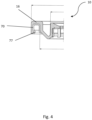
- Fig. 4 shows an example of the valve cup 10 in accordance with the third example.
- a polyester lining 70 may be provided on a surface of the valve cup 10, preferably at a portion that contacts the container 30.
- the polyester lining 70 may be formed only in a region that contacts the container 30, e.g., on the inner surfaces of the inverted U-shaped receiving portion 16, or may be formed entirely on the lower surface of the valve cup 10.
- the polyester lining 70 may be coated on the valve cup 10, or may be a separate component that is subsequently attached thereto via adhesive and/or held by the valve cup 10.
- the valve cup 10 may be configured to clamp or hold a part of the polyester lining 70.
- the polyester lining 70 may be formed from any polyester, but is preferably formed from PET.
- the valve cup 10 is formed of a metal, i.e., aluminium, or other rigid material
- the structural rigidity of the valve cup 10 at temperatures greater than 50°C is ensured by the structural rigidity of the metal or rigid material.
- the metal or rigid material does not deform at temperatures greater than 50°C. This means that the valve cup 10 may reliably hold and seal the valve 50.
- Providing the polyester lining 70 on a part of the valve cup 10 means that the polyester lining 70 can be welded using any of the aforementioned techniques to a polyester based container 30, e.g., the container 30 of the first example. In this way, the valve cup 10 can be reliably attached to the container 30 such that any deformation of the container 30 at temperatures greater than 50°C does not cause the valve cup 10 and container 30 to separate, and thus the seal therebetween is maintained.
- the polyester lining 70 may also be provided with projections 77 similar to the projections 17 of the first example.
- the projections 77 may be formed additionally as part of the polyester lining 70, i.e., varying thickness of the polyester lining 70, or they may be formed as a natural consequence of following the projections 17 when coating the valve cup 10.
- the polyester lining 70 does not have to be formed from the semi-crystalline polyesters as discussed in the first and second examples. However, in some cases, to prevent deformation of the polyester lining 70 that may lead to detachment from the valve cup 10, the polyester lining 70 may be formed from the semi-crystalline polyesters.
- valve cups 10 or container 30 as described in any of the first through third examples is now given.
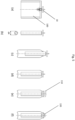
- Fig. 5 details a method of assembling the dispensing system 1 according to the present invention.
- the valve 50 is coupled to the valve cup 10.
- An exemplary method for performing this coupling has been described with respect to the first example, and so will not be repeated here. Essentially any method or coupling may be performed depending upon the exact structure of the valve 50 and the valve cup 10.
- a first step of the invention involves coupling the bag 100 to the valve 50. More specifically, an opening of the bag 100 is attached to a lower part of the valve 50, e.g., lower channel 57, such that the valve 50 can be in fluid communication with the interior of the bag 100 when actuated.
- the valve 50 may be provided with any means for facilitating this coupling, such as the recesses 58 in Fig. 1 .
- the bag 100 may be secured by any suitable means such as adhesive, welding, or clamping.
- the combination of bag 100 and valve 50 in a fixed arrangement is generally referred to as a Bag On Valve (BOV).
- the bag 100 is preferably liquid, gas, or fluid impermeable.
- the bag 100 may be folded to reduce the footprint thereof. As shown in Fig. 5(b) , the bag 100 may be folded in such a way that the footprint is less than the diameter of the valve cup 10. Preferably, the footprint is less than the diameter of the opening 32 of a container 30 to which the valve cup 10 is to be assembled such that the BOV may be inserted into the opening 32. In an exemplary method, the BOV is folded such that the footprint has a diameter d4 less than 25 mm or 22 mm, although other diameters are possible.
- the folding may be performed in any manner so as to reduce the footprint of the BOV and allow insertion into the container 30.
- the flat bag 100 is rolled around the axis of the valve 50 and valve cup 10 such that the bag 100 is in a spiralled configuration centred on the axis of the valve 50.
- the bag 100 may be folded in a concertina. In both cases, the BOV is preferably provided with a suitable footprint.
- the BOV may not be provided with a containing sleeve or tape to retain the BOV in the folded configuration.
- the folded BOV is inserted directly into the container 30, as is shown in Fig. 5(c) .
- the BOV is slid through the opening 32 of the container 30 while maintained in the folded state to improve the ease of insertion.
- the inner region of the container 30 may be filled with gas, preferably a propellant gas.
- gas preferably a propellant gas.
- Suitable propellant gasses are known in the art and are not discussed further herein.
- the method used is preferably undercup gassing, which essentially means that the gas is passed under the valve cup 10 and into the region between the bag 100 and the inner volume of the container 30.
- the inner volume of the container 30 may be pressurised to a pressure between 1 to 3 bar, preferably 1.5 to 2.5 bar.
- valve cup 10 contacts the opening 32 of the container 30.
- the valve cup 10 is provided with the inverter U-shaped receiving portion 16 and the container 30 is provided with the lip portion 38.
- the BOV may be inserted into the container 30 until the lip portion 38 of the container 30 abuts the inverted U-shaped receiving portion 16.
- the inverted U-shaped receiving portion 16 comprises the projections 17, 77 which are adapted to engage in a snap-fit manner with the underside of the lip portion 38.
- the U-shaped receiving portion 16 may deform slightly to allow the projections 17, 77 to pass over the lip portion 38 and subsequently return to their resting state once the projections 17, 77 have passed over the lip portion 38. Securing the valve cup 10 in this way aids in ensuring that the welding process is performed with improved accuracy as the valve cup 10 can be reliably aligned with the container 30.
- a welding head 110 may be positioned over the valve cup 10 in order to weld the valve cup 10 to the container 30.
- the valve cup 10 and container 30 may be formed, at least in part, from plastics. This means that welding or plastic welding, such as friction welding, ultrasonic welding, or laser welding, can be performed so as to weld the valve cup 10 to the container 30. Any of the welding techniques can be used and these techniques are generally known in the art and so are not described in any further detail herein.
- the dispensing system 1 is assembled. Further assembly steps may be possible, such as adding a protection overcap 120 to cover the exposed part of the valve 50 as in Fig. 5(f) .
- the assembled dispensing systems 1 may then be transported to various consumers to be filled with a variety of different products.
- the fluid medium to be dispensed is passed through the valve 50 into the bag 100, i.e., via upper channel 55, through hole 56, and lower channel 57.
- the pressure in the container 30 increases as the bag 100 fills with the fluid medium.
- the pressure increases to around 6 to 8 bar, preferably 6.5 to 7.5 bar. This increase in pressure aids in dispensing the fluid medium when the valve 50 is actuated by a user.
- the dispensing systems are assembled by welding the valve cup 10 to the container 30 after experiencing undercup gassing.
- Conventional methods generally rely on clinching the valve cup to the container, whereas the present assembly method utilises the welding of a specially modified valve cup 10 to a container 30.
- the welding may also be performed at lower pressures and without the presence of the fluid medium to the dispensed. This can ensure a more reliable weld and potentially prevent any contamination of the fluid medium to be dispensed.
- the present invention therefore provides a method for assembling a dispensing system 1 for dispensing a fluid medium, the dispensing system 1 including a valve cup 10 or container 30 that is modified to be rigid at temperatures exceeding 50°C, while also allowing for welding between the valve cup 10 and container 30.
- this can be achieved by using either a semi-crystalline polyester with a high degree of crystallinity, or by making use of a polyester layer on a metal or rigid material valve cup.
Landscapes
- Chemical & Material Sciences (AREA)
- Dispersion Chemistry (AREA)
- Engineering & Computer Science (AREA)
- Mechanical Engineering (AREA)
- Containers And Packaging Bodies Having A Special Means To Remove Contents (AREA)
- Packages (AREA)
- Lining Or Joining Of Plastics Or The Like (AREA)
- Nozzles (AREA)
- Filling Or Discharging Of Gas Storage Vessels (AREA)
- Closures For Containers (AREA)
Claims (17)
- Procédé d'assemblage d'un système de distribution pour distribuer un milieu fluide stocké sous pression, le procédé incluant :- la fourniture d'une coupelle de valve (10) incluant une valve (50) et un sac (100),la valve (50) étant configurée pour s'attacher à une ouverture du sac (100), dans lequel la coupelle de valve (10) est formée à partir d'un matériau métallique ou rigide et inclut une doublure (70) formée à partir d'un premier plastique qui est un polyester,dans lequel la doublure en polyester (70) est prévue au niveau d'au moins une portion de la coupelle de valve (10) qui fait face à un récipient (30) lorsqu'elle est assemblée,dans lequel la doublure en polyester (70) est soit maintenue par la coupelle de valve (10), soit est revêtue sur la coupelle de valve (10) ;- l'insertion de la valve (50) dans l'ouverture du sac (100) et le scellement étanche aux fluides du sac (100) à la valve (50) ;- la fourniture du récipient (30), le récipient (30) incluant une ouverture (32) et convenant au stockage d'un milieu fluide sous pression et formé, au moins en partie, à partir d'un second plastique ;- l'insertion du sac (100) dans le récipient (30) et le positionnement de la coupelle de valve (10) au niveau de l'ouverture (32) du récipient (30) ;- la pressurisation du volume interne du récipient (30) ; et- le soudage de la coupelle de valve (10) au récipient (30) pour fournir ainsi une étanchéité entre la coupelle de valve (10) et l'ouverture (32) du récipient (30).
- Procédé selon la revendication 1, dans lequel la première matière plastique est un polyester semi-cristallin.
- Procédé selon l'une quelconque des revendications précédentes, dans lequel la première matière plastique présente un degré de cristallinité supérieur à 35 %, de préférence supérieur à 38 %, lorsqu'il est mesuré par calorimétrie à balayage différentiel.
- Procédé selon l'une quelconque des revendications précédentes, dans lequel la première matière plastique est choisie dans le groupe consistant en : le PET cristallisé, le PBT, le PEN, des copolymères PEN/PET, ou un mélange de l'une quelconque des matières précédentes ; et la seconde matière plastique est un polyester, de préférence le PET.
- Procédé selon l'une quelconque des revendications précédentes, dans lequel le récipient (30) est entièrement formé à partir de la seconde matière plastique.
- Procédé selon l'une quelconque des revendications 1 à 3, dans lequel la seconde matière plastique est un polyester semi-cristallin.
- Procédé selon l'une quelconque des revendications 1 à 3 et 6, en particulier la revendication 6, dans lequel la seconde matière plastique présente un degré de cristallinité supérieur à 35 %, de préférence supérieur à 38 %, lorsqu'il est mesuré par calorimétrie à balayage différentiel.
- Procédé selon l'une quelconque des revendications 1 à 3 et 6 à 7, dans lequel la seconde matière plastique est choisie dans le groupe consistant en : le PET cristallisé, le PBT, le PEN, des copolymères PEN/PET, ou un mélange de l'une quelconque des matières précédentes, et la première matière plastique est un polyester, de préférence le PET.
- Procédé selon l'une quelconque des revendications précédentes, dans lequel le soudage de la coupelle de valve au récipient inclut le soudage de la coupelle de valve au récipient par l'un quelconque parmi : un soudage par frottement, un soudage par ultrasons et un soudage au laser.
- Procédé selon l'une quelconque des revendications précédentes, dans lequel la pressurisation du récipient (30) inclut la pressurisation du volume du récipient (30) entre l'intérieur du récipient (30) et l'extérieur du sac (100) entre 1 et 3 bar, de préférence entre 1,5 et 2,5 bar, par gazage sous la coupelle.
- Procédé selon l'une quelconque des revendications précédentes, la coupelle de valve (10) incluant une portion de réception en forme de U inversé (16) et le récipient (30) incluant une portion de lèvre (38), dans lequel avant de souder la coupelle de valve (10) au récipient (30), le procédé inclut en outre l'encliquetage de la portion de réception en forme de U inversé (16) sur la portion de lèvre (38).
- Procédé selon l'une quelconque des revendications précédentes, comprenant en outre, avant d'insérer le sac (100) dans le récipient (30), le pliage du sac (100) de façon à diminuer la place occupée par le sac (100) pour qu'elle soit inférieure au diamètre de l'ouverture du récipient (30).
- Procédé selon l'une quelconque des revendications précédentes, en particulier la revendication 12, dans lequel le pliage inclut la torsion du sac (100) autour d'un axe central de la valve (50) ou le pliage du sac (100) en accordéon.
- Procédé selon l'une quelconque des revendications précédentes, dans lequel la doublure en polyester (70) est fixée à la coupelle de valve (10) par un adhésif.
- Procédé selon l'une quelconque des revendications précédentes, dans lequel la doublure en polyester (70) est revêtue directement sur une surface de la coupelle de valve (10).
- Procédé selon l'une quelconque des revendications 1 à 14 précédentes, dans lequel la coupelle de valve (10) est formée de façon à pouvoir sertir ou clincher la doublure en polyester (70).
- Procédé selon l'une quelconque des revendications précédentes, dans lequel la doublure en polyester (70) est prévue sur une face inférieure de la coupelle de valve (10).
Applications Claiming Priority (3)
| Application Number | Priority Date | Filing Date | Title |
|---|---|---|---|
| EP15179629 | 2015-08-04 | ||
| EP16730330.4A EP3331775B1 (fr) | 2015-08-04 | 2016-06-14 | Procédé d'assemblage d'un système de distribution pour distribuer un milieu fluide |
| PCT/EP2016/063571 WO2017021039A1 (fr) | 2015-08-04 | 2016-06-14 | Procédé d'assemblage d'un système de distribution pour distribuer un milieu fluide |
Related Parent Applications (1)
| Application Number | Title | Priority Date | Filing Date |
|---|---|---|---|
| EP16730330.4A Division EP3331775B1 (fr) | 2015-08-04 | 2016-06-14 | Procédé d'assemblage d'un système de distribution pour distribuer un milieu fluide |
Publications (2)
| Publication Number | Publication Date |
|---|---|
| EP3683169A1 EP3683169A1 (fr) | 2020-07-22 |
| EP3683169B1 true EP3683169B1 (fr) | 2024-05-01 |
Family
ID=61975946
Family Applications (2)
| Application Number | Title | Priority Date | Filing Date |
|---|---|---|---|
| EP20159201.1A Active EP3683169B1 (fr) | 2015-08-04 | 2016-06-14 | Procédé d'assemblage d'un système de distribution pour distribuer un milieu fluide |
| EP16730330.4A Active EP3331775B1 (fr) | 2015-08-04 | 2016-06-14 | Procédé d'assemblage d'un système de distribution pour distribuer un milieu fluide |
Family Applications After (1)
| Application Number | Title | Priority Date | Filing Date |
|---|---|---|---|
| EP16730330.4A Active EP3331775B1 (fr) | 2015-08-04 | 2016-06-14 | Procédé d'assemblage d'un système de distribution pour distribuer un milieu fluide |
Country Status (6)
| Country | Link |
|---|---|
| US (1) | US20180222613A1 (fr) |
| EP (2) | EP3683169B1 (fr) |
| JP (1) | JP2018530479A (fr) |
| KR (1) | KR102691763B1 (fr) |
| CN (1) | CN108025857A (fr) |
| ES (1) | ES2791958T3 (fr) |
Families Citing this family (16)
| Publication number | Priority date | Publication date | Assignee | Title |
|---|---|---|---|---|
| US10934080B2 (en) * | 2017-01-17 | 2021-03-02 | Coster Tecnologie Speciali S.P.A. | Fluid medium dispensing system and a method of assembling a dispensing system for a fluid medium |
| FR3063074B1 (fr) * | 2017-02-20 | 2021-12-10 | Inospray | Dispositif porte valve |
| US20190276221A1 (en) * | 2018-03-06 | 2019-09-12 | The Procter & Gamble Company | Multi-piece valve stem for aerosols |
| US10486892B1 (en) * | 2018-08-22 | 2019-11-26 | The Procter & Gamble Company | Packages and arrays of packages for plastic aerosol dispensers |
| JP2020117268A (ja) * | 2019-01-23 | 2020-08-06 | 株式会社ダイゾー | 蓋体およびそれを用いた加圧製品 |
| CN114375278B (zh) * | 2019-07-24 | 2024-04-30 | 林达尔法国两合公司 | 用于压力容器的阀杯 |
| FR3099144B1 (fr) | 2019-07-24 | 2022-01-07 | Lindal France | Valve pour récipient sous pression |
| EP4003874B1 (fr) | 2019-07-26 | 2024-05-08 | The Procter & Gamble Company | Structure de valve |
| EP4003878B1 (fr) | 2019-07-26 | 2024-07-03 | The Procter & Gamble Company | Structure de valve |
| US11892084B2 (en) | 2019-07-26 | 2024-02-06 | The Procter & Gamble Company | Valve assembly for dispensers |
| WO2021022282A1 (fr) | 2019-07-26 | 2021-02-04 | The Procter & Gamble Company | Ensemble soupape destiné à des distributeurs |
| EP4003873B1 (fr) | 2019-07-26 | 2024-03-06 | The Procter & Gamble Company | Structure de valve |
| CN114206745B (zh) | 2019-07-26 | 2024-11-08 | 宝洁公司 | 用于分配器的阀组件 |
| US20210078791A1 (en) | 2019-09-13 | 2021-03-18 | The Procter & Gamble Company | Apparatus and Method of Making an Aerosol Dispenser |
| CN113950508B (zh) | 2020-03-31 | 2023-07-14 | 东丽株式会社 | 聚酯树脂组合物、成型品及复合成型品 |
| CN113739639A (zh) * | 2021-07-26 | 2021-12-03 | 樊少佑 | 一种一体式二元防狼喷雾器的制造工艺 |
Family Cites Families (11)
| Publication number | Priority date | Publication date | Assignee | Title |
|---|---|---|---|---|
| DE3737265A1 (de) | 1987-11-03 | 1989-05-18 | Future Patents Dev Fpd | Vorrichtung zum verspruehen einer unter druck stehenden fluessigkeit, paste oder dgl. |
| US5804016A (en) * | 1996-03-07 | 1998-09-08 | Continental Pet Technologies, Inc. | Multilayer container resistant to elevated temperatures and pressures, and method of making the same |
| US7028866B2 (en) * | 2003-01-31 | 2006-04-18 | S.C. Johnson & Son, Inc. | Pressurized plastic bottle for dispensing an aerosol |
| FR2895735B1 (fr) * | 2005-12-30 | 2008-04-18 | Ecopack France | Valve a poche amelioree |
| US8960503B2 (en) * | 2006-10-19 | 2015-02-24 | Atef Gabr Soliman | Plastic aerosol container |
| WO2009006137A1 (fr) * | 2007-07-03 | 2009-01-08 | Glaxo Group Limited | Cartouche d'aérosol employant un film polymère ayant des propriétés de barrière à l'humidité améliorées |
| DE102007051982A1 (de) * | 2007-08-29 | 2009-03-05 | Seaquist Perfect Dispensing Gmbh | Abgabevorrichtung |
| US20100270002A1 (en) * | 2008-08-05 | 2010-10-28 | Parrella Michael J | System and method of maximizing performance of a solid-state closed loop well heat exchanger |
| US7821830B2 (en) * | 2008-07-23 | 2010-10-26 | Micron Technology, Inc. | Flash memory device with redundant columns |
| US9475636B2 (en) * | 2010-12-22 | 2016-10-25 | Daizo Corporation | Valve assembly and aerosol container equipped with the same, and aerosol product and process for production thereof |
| US9758294B2 (en) * | 2013-01-25 | 2017-09-12 | The Procter & Gamble Company | Components for aerosol dispenser and aerosol dispenser made therewith |
-
2016
- 2016-06-14 EP EP20159201.1A patent/EP3683169B1/fr active Active
- 2016-06-14 JP JP2018506112A patent/JP2018530479A/ja not_active Withdrawn
- 2016-06-14 US US15/749,615 patent/US20180222613A1/en not_active Abandoned
- 2016-06-14 KR KR1020187004582A patent/KR102691763B1/ko active Active
- 2016-06-14 ES ES16730330T patent/ES2791958T3/es active Active
- 2016-06-14 EP EP16730330.4A patent/EP3331775B1/fr active Active
- 2016-06-14 CN CN201680044875.9A patent/CN108025857A/zh active Pending
Non-Patent Citations (1)
| Title |
|---|
| YERBY TIM: "Aerosol Valves", 28 May 2015 (2015-05-28), pages 1 - 91, XP055801786, Retrieved from the Internet <URL:http://citenpl.internal.epo.org/wf/storage/1793E64E7200002CC85/originalPdf#zoom=100> [retrieved on 20210505] * |
Also Published As
| Publication number | Publication date |
|---|---|
| EP3331775B1 (fr) | 2020-02-26 |
| US20180222613A1 (en) | 2018-08-09 |
| EP3683169A1 (fr) | 2020-07-22 |
| KR102691763B1 (ko) | 2024-08-02 |
| ES2791958T3 (es) | 2020-11-06 |
| CN108025857A (zh) | 2018-05-11 |
| KR20180037205A (ko) | 2018-04-11 |
| EP3331775A1 (fr) | 2018-06-13 |
| JP2018530479A (ja) | 2018-10-18 |
Similar Documents
| Publication | Publication Date | Title |
|---|---|---|
| EP3683169B1 (fr) | Procédé d'assemblage d'un système de distribution pour distribuer un milieu fluide | |
| EP3331776B1 (fr) | Coupelles de valve et récipients à utiliser dans des systèmes de distribution de milieu fluide | |
| WO2017021039A1 (fr) | Procédé d'assemblage d'un système de distribution pour distribuer un milieu fluide | |
| KR102396798B1 (ko) | 용기를 위한 혼합/폐쇄 디바이스 및 폐쇄 디바이스로부터 매질을 분배시키기 위한 방법 | |
| US20140263436A1 (en) | Container | |
| US20160023818A1 (en) | Container | |
| CN110621593A (zh) | 用于气溶胶分配器的容器、具有容器的气溶胶分配器和用于气溶胶分配器的预成型件容器 | |
| JP6236247B2 (ja) | 吐出容器 | |
| US10934080B2 (en) | Fluid medium dispensing system and a method of assembling a dispensing system for a fluid medium | |
| US20190161268A1 (en) | Fluid medium dispensing system and a method of assembling a dispensing system for a fluid medium | |
| JP5965580B2 (ja) | 容器口部のシール構造 | |
| US10926942B2 (en) | Aerosol valve configurations | |
| CN113056426B (zh) | 用于容器的分配封闭件 | |
| US20100320230A1 (en) | Adapter for connecting aerosol valve to pouch of high pressure vessel | |
| JP2012250755A (ja) | 二重エアゾール容器およびその製造方法 | |
| KR20200064333A (ko) | 혼합용기 및 그 제조방법 | |
| JP2014015246A (ja) | 吐出容器 | |
| JP2010202207A (ja) | ステンレス鋼製断熱2重構造ボトル |
Legal Events
| Date | Code | Title | Description |
|---|---|---|---|
| PUAI | Public reference made under article 153(3) epc to a published international application that has entered the european phase |
Free format text: ORIGINAL CODE: 0009012 |
|
| STAA | Information on the status of an ep patent application or granted ep patent |
Free format text: STATUS: THE APPLICATION HAS BEEN PUBLISHED |
|
| AC | Divisional application: reference to earlier application |
Ref document number: 3331775 Country of ref document: EP Kind code of ref document: P |
|
| AK | Designated contracting states |
Kind code of ref document: A1 Designated state(s): AL AT BE BG CH CY CZ DE DK EE ES FI FR GB GR HR HU IE IS IT LI LT LU LV MC MK MT NL NO PL PT RO RS SE SI SK SM TR |
|
| STAA | Information on the status of an ep patent application or granted ep patent |
Free format text: STATUS: REQUEST FOR EXAMINATION WAS MADE |
|
| 17P | Request for examination filed |
Effective date: 20210122 |
|
| RBV | Designated contracting states (corrected) |
Designated state(s): AL AT BE BG CH CY CZ DE DK EE ES FI FR GB GR HR HU IE IS IT LI LT LU LV MC MK MT NL NO PL PT RO RS SE SI SK SM TR |
|
| STAA | Information on the status of an ep patent application or granted ep patent |
Free format text: STATUS: EXAMINATION IS IN PROGRESS |
|
| 17Q | First examination report despatched |
Effective date: 20210512 |
|
| P01 | Opt-out of the competence of the unified patent court (upc) registered |
Effective date: 20230601 |
|
| GRAP | Despatch of communication of intention to grant a patent |
Free format text: ORIGINAL CODE: EPIDOSNIGR1 |
|
| STAA | Information on the status of an ep patent application or granted ep patent |
Free format text: STATUS: GRANT OF PATENT IS INTENDED |
|
| INTG | Intention to grant announced |
Effective date: 20231201 |
|
| GRAS | Grant fee paid |
Free format text: ORIGINAL CODE: EPIDOSNIGR3 |
|
| GRAA | (expected) grant |
Free format text: ORIGINAL CODE: 0009210 |
|
| STAA | Information on the status of an ep patent application or granted ep patent |
Free format text: STATUS: THE PATENT HAS BEEN GRANTED |
|
| AC | Divisional application: reference to earlier application |
Ref document number: 3331775 Country of ref document: EP Kind code of ref document: P |
|
| AK | Designated contracting states |
Kind code of ref document: B1 Designated state(s): AL AT BE BG CH CY CZ DE DK EE ES FI FR GB GR HR HU IE IS IT LI LT LU LV MC MK MT NL NO PL PT RO RS SE SI SK SM TR |
|
| REG | Reference to a national code |
Ref country code: GB Ref legal event code: FG4D |
|
| REG | Reference to a national code |
Ref country code: CH Ref legal event code: EP |
|
| REG | Reference to a national code |
Ref country code: IE Ref legal event code: FG4D |
|
| REG | Reference to a national code |
Ref country code: DE Ref legal event code: R096 Ref document number: 602016087365 Country of ref document: DE |
|
| PGFP | Annual fee paid to national office [announced via postgrant information from national office to epo] |
Ref country code: DE Payment date: 20240628 Year of fee payment: 9 |
|
| PGFP | Annual fee paid to national office [announced via postgrant information from national office to epo] |
Ref country code: FR Payment date: 20240625 Year of fee payment: 9 |
|
| REG | Reference to a national code |
Ref country code: LT Ref legal event code: MG9D |
|
| REG | Reference to a national code |
Ref country code: NL Ref legal event code: MP Effective date: 20240501 |
|
| PG25 | Lapsed in a contracting state [announced via postgrant information from national office to epo] |
Ref country code: IS Free format text: LAPSE BECAUSE OF FAILURE TO SUBMIT A TRANSLATION OF THE DESCRIPTION OR TO PAY THE FEE WITHIN THE PRESCRIBED TIME-LIMIT Effective date: 20240901 |
|
| PG25 | Lapsed in a contracting state [announced via postgrant information from national office to epo] |
Ref country code: BG Free format text: LAPSE BECAUSE OF FAILURE TO SUBMIT A TRANSLATION OF THE DESCRIPTION OR TO PAY THE FEE WITHIN THE PRESCRIBED TIME-LIMIT Effective date: 20240501 |
|
| PG25 | Lapsed in a contracting state [announced via postgrant information from national office to epo] |
Ref country code: HR Free format text: LAPSE BECAUSE OF FAILURE TO SUBMIT A TRANSLATION OF THE DESCRIPTION OR TO PAY THE FEE WITHIN THE PRESCRIBED TIME-LIMIT Effective date: 20240501 Ref country code: FI Free format text: LAPSE BECAUSE OF FAILURE TO SUBMIT A TRANSLATION OF THE DESCRIPTION OR TO PAY THE FEE WITHIN THE PRESCRIBED TIME-LIMIT Effective date: 20240501 |
|
| PG25 | Lapsed in a contracting state [announced via postgrant information from national office to epo] |
Ref country code: GR Free format text: LAPSE BECAUSE OF FAILURE TO SUBMIT A TRANSLATION OF THE DESCRIPTION OR TO PAY THE FEE WITHIN THE PRESCRIBED TIME-LIMIT Effective date: 20240802 |
|
| PG25 | Lapsed in a contracting state [announced via postgrant information from national office to epo] |
Ref country code: PT Free format text: LAPSE BECAUSE OF FAILURE TO SUBMIT A TRANSLATION OF THE DESCRIPTION OR TO PAY THE FEE WITHIN THE PRESCRIBED TIME-LIMIT Effective date: 20240902 |
|
| REG | Reference to a national code |
Ref country code: AT Ref legal event code: MK05 Ref document number: 1682086 Country of ref document: AT Kind code of ref document: T Effective date: 20240501 |
|
| PG25 | Lapsed in a contracting state [announced via postgrant information from national office to epo] |
Ref country code: NL Free format text: LAPSE BECAUSE OF FAILURE TO SUBMIT A TRANSLATION OF THE DESCRIPTION OR TO PAY THE FEE WITHIN THE PRESCRIBED TIME-LIMIT Effective date: 20240501 |
|
| PG25 | Lapsed in a contracting state [announced via postgrant information from national office to epo] |
Ref country code: ES Free format text: LAPSE BECAUSE OF FAILURE TO SUBMIT A TRANSLATION OF THE DESCRIPTION OR TO PAY THE FEE WITHIN THE PRESCRIBED TIME-LIMIT Effective date: 20240501 |
|
| PG25 | Lapsed in a contracting state [announced via postgrant information from national office to epo] |
Ref country code: AT Free format text: LAPSE BECAUSE OF FAILURE TO SUBMIT A TRANSLATION OF THE DESCRIPTION OR TO PAY THE FEE WITHIN THE PRESCRIBED TIME-LIMIT Effective date: 20240501 |
|
| PG25 | Lapsed in a contracting state [announced via postgrant information from national office to epo] |
Ref country code: PL Free format text: LAPSE BECAUSE OF FAILURE TO SUBMIT A TRANSLATION OF THE DESCRIPTION OR TO PAY THE FEE WITHIN THE PRESCRIBED TIME-LIMIT Effective date: 20240501 |
|
| PG25 | Lapsed in a contracting state [announced via postgrant information from national office to epo] |
Ref country code: LV Free format text: LAPSE BECAUSE OF FAILURE TO SUBMIT A TRANSLATION OF THE DESCRIPTION OR TO PAY THE FEE WITHIN THE PRESCRIBED TIME-LIMIT Effective date: 20240501 |
|
| PG25 | Lapsed in a contracting state [announced via postgrant information from national office to epo] |
Ref country code: PT Free format text: LAPSE BECAUSE OF FAILURE TO SUBMIT A TRANSLATION OF THE DESCRIPTION OR TO PAY THE FEE WITHIN THE PRESCRIBED TIME-LIMIT Effective date: 20240902 Ref country code: PL Free format text: LAPSE BECAUSE OF FAILURE TO SUBMIT A TRANSLATION OF THE DESCRIPTION OR TO PAY THE FEE WITHIN THE PRESCRIBED TIME-LIMIT Effective date: 20240501 Ref country code: NO Free format text: LAPSE BECAUSE OF FAILURE TO SUBMIT A TRANSLATION OF THE DESCRIPTION OR TO PAY THE FEE WITHIN THE PRESCRIBED TIME-LIMIT Effective date: 20240801 Ref country code: NL Free format text: LAPSE BECAUSE OF FAILURE TO SUBMIT A TRANSLATION OF THE DESCRIPTION OR TO PAY THE FEE WITHIN THE PRESCRIBED TIME-LIMIT Effective date: 20240501 Ref country code: LV Free format text: LAPSE BECAUSE OF FAILURE TO SUBMIT A TRANSLATION OF THE DESCRIPTION OR TO PAY THE FEE WITHIN THE PRESCRIBED TIME-LIMIT Effective date: 20240501 Ref country code: IS Free format text: LAPSE BECAUSE OF FAILURE TO SUBMIT A TRANSLATION OF THE DESCRIPTION OR TO PAY THE FEE WITHIN THE PRESCRIBED TIME-LIMIT Effective date: 20240901 Ref country code: HR Free format text: LAPSE BECAUSE OF FAILURE TO SUBMIT A TRANSLATION OF THE DESCRIPTION OR TO PAY THE FEE WITHIN THE PRESCRIBED TIME-LIMIT Effective date: 20240501 Ref country code: GR Free format text: LAPSE BECAUSE OF FAILURE TO SUBMIT A TRANSLATION OF THE DESCRIPTION OR TO PAY THE FEE WITHIN THE PRESCRIBED TIME-LIMIT Effective date: 20240802 Ref country code: FI Free format text: LAPSE BECAUSE OF FAILURE TO SUBMIT A TRANSLATION OF THE DESCRIPTION OR TO PAY THE FEE WITHIN THE PRESCRIBED TIME-LIMIT Effective date: 20240501 Ref country code: ES Free format text: LAPSE BECAUSE OF FAILURE TO SUBMIT A TRANSLATION OF THE DESCRIPTION OR TO PAY THE FEE WITHIN THE PRESCRIBED TIME-LIMIT Effective date: 20240501 Ref country code: BG Free format text: LAPSE BECAUSE OF FAILURE TO SUBMIT A TRANSLATION OF THE DESCRIPTION OR TO PAY THE FEE WITHIN THE PRESCRIBED TIME-LIMIT Effective date: 20240501 Ref country code: AT Free format text: LAPSE BECAUSE OF FAILURE TO SUBMIT A TRANSLATION OF THE DESCRIPTION OR TO PAY THE FEE WITHIN THE PRESCRIBED TIME-LIMIT Effective date: 20240501 Ref country code: RS Free format text: LAPSE BECAUSE OF FAILURE TO SUBMIT A TRANSLATION OF THE DESCRIPTION OR TO PAY THE FEE WITHIN THE PRESCRIBED TIME-LIMIT Effective date: 20240801 |
|
| PGFP | Annual fee paid to national office [announced via postgrant information from national office to epo] |
Ref country code: IT Payment date: 20240723 Year of fee payment: 9 |
|
| PG25 | Lapsed in a contracting state [announced via postgrant information from national office to epo] |
Ref country code: DK Free format text: LAPSE BECAUSE OF FAILURE TO SUBMIT A TRANSLATION OF THE DESCRIPTION OR TO PAY THE FEE WITHIN THE PRESCRIBED TIME-LIMIT Effective date: 20240501 |
|
| PG25 | Lapsed in a contracting state [announced via postgrant information from national office to epo] |
Ref country code: EE Free format text: LAPSE BECAUSE OF FAILURE TO SUBMIT A TRANSLATION OF THE DESCRIPTION OR TO PAY THE FEE WITHIN THE PRESCRIBED TIME-LIMIT Effective date: 20240501 |
|
| PG25 | Lapsed in a contracting state [announced via postgrant information from national office to epo] |
Ref country code: CZ Free format text: LAPSE BECAUSE OF FAILURE TO SUBMIT A TRANSLATION OF THE DESCRIPTION OR TO PAY THE FEE WITHIN THE PRESCRIBED TIME-LIMIT Effective date: 20240501 |
|
| PG25 | Lapsed in a contracting state [announced via postgrant information from national office to epo] |
Ref country code: SK Free format text: LAPSE BECAUSE OF FAILURE TO SUBMIT A TRANSLATION OF THE DESCRIPTION OR TO PAY THE FEE WITHIN THE PRESCRIBED TIME-LIMIT Effective date: 20240501 Ref country code: RO Free format text: LAPSE BECAUSE OF FAILURE TO SUBMIT A TRANSLATION OF THE DESCRIPTION OR TO PAY THE FEE WITHIN THE PRESCRIBED TIME-LIMIT Effective date: 20240501 |
|
| PG25 | Lapsed in a contracting state [announced via postgrant information from national office to epo] |
Ref country code: SM Free format text: LAPSE BECAUSE OF FAILURE TO SUBMIT A TRANSLATION OF THE DESCRIPTION OR TO PAY THE FEE WITHIN THE PRESCRIBED TIME-LIMIT Effective date: 20240501 |
|
| PG25 | Lapsed in a contracting state [announced via postgrant information from national office to epo] |
Ref country code: SM Free format text: LAPSE BECAUSE OF FAILURE TO SUBMIT A TRANSLATION OF THE DESCRIPTION OR TO PAY THE FEE WITHIN THE PRESCRIBED TIME-LIMIT Effective date: 20240501 Ref country code: SK Free format text: LAPSE BECAUSE OF FAILURE TO SUBMIT A TRANSLATION OF THE DESCRIPTION OR TO PAY THE FEE WITHIN THE PRESCRIBED TIME-LIMIT Effective date: 20240501 Ref country code: RO Free format text: LAPSE BECAUSE OF FAILURE TO SUBMIT A TRANSLATION OF THE DESCRIPTION OR TO PAY THE FEE WITHIN THE PRESCRIBED TIME-LIMIT Effective date: 20240501 Ref country code: EE Free format text: LAPSE BECAUSE OF FAILURE TO SUBMIT A TRANSLATION OF THE DESCRIPTION OR TO PAY THE FEE WITHIN THE PRESCRIBED TIME-LIMIT Effective date: 20240501 Ref country code: DK Free format text: LAPSE BECAUSE OF FAILURE TO SUBMIT A TRANSLATION OF THE DESCRIPTION OR TO PAY THE FEE WITHIN THE PRESCRIBED TIME-LIMIT Effective date: 20240501 Ref country code: CZ Free format text: LAPSE BECAUSE OF FAILURE TO SUBMIT A TRANSLATION OF THE DESCRIPTION OR TO PAY THE FEE WITHIN THE PRESCRIBED TIME-LIMIT Effective date: 20240501 Ref country code: MC Free format text: LAPSE BECAUSE OF FAILURE TO SUBMIT A TRANSLATION OF THE DESCRIPTION OR TO PAY THE FEE WITHIN THE PRESCRIBED TIME-LIMIT Effective date: 20240501 |
|
| REG | Reference to a national code |
Ref country code: CH Ref legal event code: PL |
|
| REG | Reference to a national code |
Ref country code: DE Ref legal event code: R097 Ref document number: 602016087365 Country of ref document: DE |
|
| PG25 | Lapsed in a contracting state [announced via postgrant information from national office to epo] |
Ref country code: LU Free format text: LAPSE BECAUSE OF NON-PAYMENT OF DUE FEES Effective date: 20240614 |
|
| PLBE | No opposition filed within time limit |
Free format text: ORIGINAL CODE: 0009261 |
|
| STAA | Information on the status of an ep patent application or granted ep patent |
Free format text: STATUS: NO OPPOSITION FILED WITHIN TIME LIMIT |
|
| 26N | No opposition filed |
Effective date: 20250204 |
|
| PG25 | Lapsed in a contracting state [announced via postgrant information from national office to epo] |
Ref country code: IE Free format text: LAPSE BECAUSE OF NON-PAYMENT OF DUE FEES Effective date: 20240614 |
|
| GBPC | Gb: european patent ceased through non-payment of renewal fee |
Effective date: 20240801 |
|
| PG25 | Lapsed in a contracting state [announced via postgrant information from national office to epo] |
Ref country code: SI Free format text: LAPSE BECAUSE OF FAILURE TO SUBMIT A TRANSLATION OF THE DESCRIPTION OR TO PAY THE FEE WITHIN THE PRESCRIBED TIME-LIMIT Effective date: 20240501 Ref country code: BE Free format text: LAPSE BECAUSE OF NON-PAYMENT OF DUE FEES Effective date: 20240630 Ref country code: CH Free format text: LAPSE BECAUSE OF NON-PAYMENT OF DUE FEES Effective date: 20240630 |
|
| REG | Reference to a national code |
Ref country code: BE Ref legal event code: MM Effective date: 20240630 |
|
| PG25 | Lapsed in a contracting state [announced via postgrant information from national office to epo] |
Ref country code: GB Free format text: LAPSE BECAUSE OF NON-PAYMENT OF DUE FEES Effective date: 20240801 |
|
| PG25 | Lapsed in a contracting state [announced via postgrant information from national office to epo] |
Ref country code: SE Free format text: LAPSE BECAUSE OF FAILURE TO SUBMIT A TRANSLATION OF THE DESCRIPTION OR TO PAY THE FEE WITHIN THE PRESCRIBED TIME-LIMIT Effective date: 20240501 |
|
| PG25 | Lapsed in a contracting state [announced via postgrant information from national office to epo] |
Ref country code: CY Free format text: LAPSE BECAUSE OF FAILURE TO SUBMIT A TRANSLATION OF THE DESCRIPTION OR TO PAY THE FEE WITHIN THE PRESCRIBED TIME-LIMIT; INVALID AB INITIO Effective date: 20160614 |
|
| REG | Reference to a national code |
Ref country code: DE Ref legal event code: R119 Ref document number: 602016087365 Country of ref document: DE |
|
| PG25 | Lapsed in a contracting state [announced via postgrant information from national office to epo] |
Ref country code: HU Free format text: LAPSE BECAUSE OF FAILURE TO SUBMIT A TRANSLATION OF THE DESCRIPTION OR TO PAY THE FEE WITHIN THE PRESCRIBED TIME-LIMIT; INVALID AB INITIO Effective date: 20160614 |
|
| PG25 | Lapsed in a contracting state [announced via postgrant information from national office to epo] |
Ref country code: DE Free format text: LAPSE BECAUSE OF NON-PAYMENT OF DUE FEES Effective date: 20260101 |
|
| PG25 | Lapsed in a contracting state [announced via postgrant information from national office to epo] |
Ref country code: IT Free format text: LAPSE BECAUSE OF NON-PAYMENT OF DUE FEES Effective date: 20250614 |
|
| PG25 | Lapsed in a contracting state [announced via postgrant information from national office to epo] |
Ref country code: FR Free format text: LAPSE BECAUSE OF NON-PAYMENT OF DUE FEES Effective date: 20250630 |