EP3683368A1 - Verfahren und anordnung zur montage einer durchführungsvorrichtung in einer wand - Google Patents
Verfahren und anordnung zur montage einer durchführungsvorrichtung in einer wand Download PDFInfo
- Publication number
- EP3683368A1 EP3683368A1 EP20151589.7A EP20151589A EP3683368A1 EP 3683368 A1 EP3683368 A1 EP 3683368A1 EP 20151589 A EP20151589 A EP 20151589A EP 3683368 A1 EP3683368 A1 EP 3683368A1
- Authority
- EP
- European Patent Office
- Prior art keywords
- wall
- lead
- assembly
- mounting bracket
- passage portion
- Prior art date
- Legal status (The legal status is an assumption and is not a legal conclusion. Google has not performed a legal analysis and makes no representation as to the accuracy of the status listed.)
- Granted
Links
Images


Classifications
-
- F—MECHANICAL ENGINEERING; LIGHTING; HEATING; WEAPONS; BLASTING
- F16—ENGINEERING ELEMENTS AND UNITS; GENERAL MEASURES FOR PRODUCING AND MAINTAINING EFFECTIVE FUNCTIONING OF MACHINES OR INSTALLATIONS; THERMAL INSULATION IN GENERAL
- F16L—PIPES; JOINTS OR FITTINGS FOR PIPES; SUPPORTS FOR PIPES, CABLES OR PROTECTIVE TUBING; MEANS FOR THERMAL INSULATION IN GENERAL
- F16L5/00—Devices for use where pipes, cables or protective tubing pass through walls or partitions
- F16L5/02—Sealing
- F16L5/12—Sealing the pipe being cut in two pieces
-
- E—FIXED CONSTRUCTIONS
- E03—WATER SUPPLY; SEWERAGE
- E03C—DOMESTIC PLUMBING INSTALLATIONS FOR FRESH WATER OR WASTE WATER; SINKS
- E03C1/00—Domestic plumbing installations for fresh water or waste water; Sinks
- E03C1/02—Plumbing installations for fresh water
- E03C1/021—Devices for positioning or connecting of water supply lines
-
- E—FIXED CONSTRUCTIONS
- E03—WATER SUPPLY; SEWERAGE
- E03C—DOMESTIC PLUMBING INSTALLATIONS FOR FRESH WATER OR WASTE WATER; SINKS
- E03C1/00—Domestic plumbing installations for fresh water or waste water; Sinks
- E03C1/02—Plumbing installations for fresh water
- E03C1/04—Water-basin installations specially adapted to wash-basins or baths
- E03C1/0401—Fixing a tap to the sanitary appliance or to an associated mounting surface, e.g. a countertop
-
- E—FIXED CONSTRUCTIONS
- E03—WATER SUPPLY; SEWERAGE
- E03C—DOMESTIC PLUMBING INSTALLATIONS FOR FRESH WATER OR WASTE WATER; SINKS
- E03C1/00—Domestic plumbing installations for fresh water or waste water; Sinks
- E03C1/02—Plumbing installations for fresh water
- E03C1/04—Water-basin installations specially adapted to wash-basins or baths
- E03C1/042—Arrangements on taps for wash-basins or baths for connecting to the wall
-
- F—MECHANICAL ENGINEERING; LIGHTING; HEATING; WEAPONS; BLASTING
- F16—ENGINEERING ELEMENTS AND UNITS; GENERAL MEASURES FOR PRODUCING AND MAINTAINING EFFECTIVE FUNCTIONING OF MACHINES OR INSTALLATIONS; THERMAL INSULATION IN GENERAL
- F16L—PIPES; JOINTS OR FITTINGS FOR PIPES; SUPPORTS FOR PIPES, CABLES OR PROTECTIVE TUBING; MEANS FOR THERMAL INSULATION IN GENERAL
- F16L3/00—Supports for pipes, cables or protective tubing, e.g. hangers, holders, clamps, cleats, clips, brackets
- F16L3/08—Supports for pipes, cables or protective tubing, e.g. hangers, holders, clamps, cleats, clips, brackets substantially surrounding the pipe, cable or protective tubing
- F16L3/12—Supports for pipes, cables or protective tubing, e.g. hangers, holders, clamps, cleats, clips, brackets substantially surrounding the pipe, cable or protective tubing comprising a member substantially surrounding the pipe, cable or protective tubing
- F16L3/1226—Supports for pipes, cables or protective tubing, e.g. hangers, holders, clamps, cleats, clips, brackets substantially surrounding the pipe, cable or protective tubing comprising a member substantially surrounding the pipe, cable or protective tubing elongated supports, e.g. to support a curved pipe
-
- F—MECHANICAL ENGINEERING; LIGHTING; HEATING; WEAPONS; BLASTING
- F16—ENGINEERING ELEMENTS AND UNITS; GENERAL MEASURES FOR PRODUCING AND MAINTAINING EFFECTIVE FUNCTIONING OF MACHINES OR INSTALLATIONS; THERMAL INSULATION IN GENERAL
- F16L—PIPES; JOINTS OR FITTINGS FOR PIPES; SUPPORTS FOR PIPES, CABLES OR PROTECTIVE TUBING; MEANS FOR THERMAL INSULATION IN GENERAL
- F16L41/00—Branching pipes; Joining pipes to walls
- F16L41/08—Joining pipes to walls or pipes, the joined pipe axis being perpendicular to the plane of a wall or to the axis of another pipe
- F16L41/088—Joining pipes to walls or pipes, the joined pipe axis being perpendicular to the plane of a wall or to the axis of another pipe fixed using an elastic grommet between the extremity of the tube and the wall
-
- F—MECHANICAL ENGINEERING; LIGHTING; HEATING; WEAPONS; BLASTING
- F16—ENGINEERING ELEMENTS AND UNITS; GENERAL MEASURES FOR PRODUCING AND MAINTAINING EFFECTIVE FUNCTIONING OF MACHINES OR INSTALLATIONS; THERMAL INSULATION IN GENERAL
- F16L—PIPES; JOINTS OR FITTINGS FOR PIPES; SUPPORTS FOR PIPES, CABLES OR PROTECTIVE TUBING; MEANS FOR THERMAL INSULATION IN GENERAL
- F16L41/00—Branching pipes; Joining pipes to walls
- F16L41/08—Joining pipes to walls or pipes, the joined pipe axis being perpendicular to the plane of a wall or to the axis of another pipe
- F16L41/14—Joining pipes to walls or pipes, the joined pipe axis being perpendicular to the plane of a wall or to the axis of another pipe by screwing an intermediate part against the inside or outside of the wall
-
- E—FIXED CONSTRUCTIONS
- E03—WATER SUPPLY; SEWERAGE
- E03C—DOMESTIC PLUMBING INSTALLATIONS FOR FRESH WATER OR WASTE WATER; SINKS
- E03C1/00—Domestic plumbing installations for fresh water or waste water; Sinks
- E03C1/02—Plumbing installations for fresh water
- E03C2001/028—Alignment aids for plumbing installations
Definitions
- the present invention relates to a method for mounting a lead-through assembly in a wall.
- the present invention also relates to a lead-through assembly adapted to provide a fluid communication through a wall.
- Water pipes in buildings are commonly arranged inside walls of the building.
- So called lead-through devices are positioned inside the walls and used to bring the water pipes into the rooms where faucets or other water outlets are to be installed.
- a wall bend fixture requires no water coupling inside the wall. Instead, the water pipe is bent by an angle of 90° and brought out through the wallboard inside which the wall bend fixture is installed. This is particularly suitable for mounting in e.g. a bathroom having a moisture barrier provided in its wall.
- a wall box is a sealed box intended to be mounted inside the wall, with a water coupling provided inside the box.
- the water pipe is connected to the water coupling, and the wall coupling is in turn connected to e.g. a water blender in a bathroom or similar.
- the lead-through device requires an opening in the wall through which a portion of the lead-through device and/or the water pipes may protrude and provide connection to a faucet, blender or other type of water outlet.
- the lead-through device is subjected to forces at its connection to the water outlet and thus requires a stable installation in the wall.
- this is in part solved by placing for example a plywood sheet behind the wallboard, e.g. plasterboard. In this way a double wall construction is created, in which the plywood sheet provides the support needed for mounting the lead-through device.
- the object of the present invention is to provide an improved mounting of a lead-through device in a wall.
- a first aspect of the present invention relates to a method for mounting a lead-through assembly in a wall.
- the lead-through assembly is adapted to provide a fluid communication through the wall in a direction of extension from a first side of the wall to a second side of the wall.
- the lead-through assembly comprises:
- a method as recited above implies a mounting of a lead-through assembly fixed in the wall by means of clamping, thus reducing the need to drill and possibly destroy a moisture barrier of a wall in which the lead-through assembly is installed.
- the securing of the at least one support section serves to keep the lead-through device in position while the retainer is attached.
- the lead-through device is temporarily, or preliminary, secured to the first wall surface.
- the securing of the at least one support section is not intended to provide the fixing itself of the lead-through device, merely to position the lead-through device while the retainer is attached.
- the method may comprise securing the at least one support section , and thus the abutment surface, to the first wall surface by securing means extending in a direction from the second side of the wall and through the wall.
- securing means may in this case be e.g. screws or nails.
- the steps of securing and fixing of the lead-through device is thus carried out form the second side of the wall.
- the securing means may be inserted directly through the wall without any intermediate step of providing a guiding plate, washer or similar part, located on the second wall surface.
- This has the positive effect of reducing the interference with the moisture barrier.
- the lead-through assembly may however as an alternative or complement, be secured to the first wall surface by means of e.g. an adhesive, i.e. by gluing.
- an adhesive i.e. by gluing.
- from which side the at least one support section is secured may vary e.g. depending on the structure of wall and the available space and access around it.
- the lead-through device may comprise the at least one support section. This has the positive effect of providing a simple mounting with few parts.
- the lead-through assembly may comprise a mounting bracket.
- the mounting bracket is adapted to receive the lead-through device such that the passage portion extends through an opening in the mounting bracket.
- the mounting bracket comprises the at least one support section.
- the method may further comprise:
- the above listed steps of the method may be carried out in any order deemed appropriate.
- the at least one support section may be secured to the first wall surface before or after attachment of the lead-through device to the mounting bracket.
- a mounting bracket when installing the lead-through device serves to simplify and facilitate the mounting.
- a mounting bracket also provides additional support for the clamping of the lead-through assembly in the wall. In this way, the mounting of the lead-through device may be substantially independent of the supporting capability of the wall construction itself.
- the method involving a mounting bracket is thus advantageous when used on a wall construction comprising a single wallboard, e.g. plasterboard.
- the mounting bracket provides the desired stability by which the lead-through device may be clamped to the wall by the attached retainer.
- the use of a mounting bracket may facilitate the positioning of the lead-through device.
- the contact surface of the retainer abuts a surface on the second side of the wall structure, and thereby a clamping force arises between the abutment surface and the contact surface which clamps the lead-through device to the wall.
- the lead-through device is fixed in the wall solely by the clamping force between the at least one support section and the retainer.
- the securing of the mounting bracket serves to keep the lead-through device in position while the retainer is attached.
- the mounting bracket is temporarily, or preliminary, secured to the first side of the wall.
- the securing of the mounting bracket is not intended to provide the fixing itself of the lead-through device, merely to position it while the retainer is attached.
- a lead-through device as used herein may comprise a wall box or a wall bend fixture as outlined above.
- the first side of the wall may correspond to an inlet side of the wall and the second side of the wall may correspond to an outlet side of the wall.
- the wall in which the lead-through device is installed is commonly provided with a moisture barrier on the inside, and thus constitutes a wall of a wet space, such as a bathroom.
- the second side of the wall may thus represent the side of the wall facing the wet space.
- a faucet, blender or other type of water outlet is, in this case, typically connected to the lead-through device on the second side of the wall.
- the second side of the wall may correspond to an outlet side of the wall.
- the first side of the wall is opposite the second side.
- the water pipes leading up to the lead-through device may extend on the first side, which in this case corresponds to an inlet side of the wall.
- the mounting bracket may be secured to the wall by securing means, such as an adhesive or screws.
- the securing of the mounting bracket is intended to hold the lead-through device in position, such that the retainer may be attached to the passage portion of the lead-through device. Noticeably, the securing of the mounting bracket is not intended to fix the lead-through device in the wall.
- the abutment surface may be used to secure the mounting bracket. By way of example, the abutment surface may serve as an attachment zone for an adhesive or as an attachment zone for one or more screws.
- the method may comprise securing the mounting bracket to the first wall surface by securing means extending in a direction from the second side of the wall and through the wall.
- securing means extending in a direction from the second side of the wall and through the wall.
- the abutment surface may serve as attachment zone for one or more screws or nails being attached from the second side of the wall to secure the mounting bracket on the first side of the wall. In this way, when the second side of the wall corresponds to an outlet side of the wall, the mounting bracket may be secured in an easy and accessible manner.
- the at least one support section of the mounting bracket in addition to providing support for clamping the lead-through device to the wall, may also provide an attachment zone for securing means used to secure the mounting bracket.
- the mounting bracket may be secured by one or more screws, screwed from the second side, through the wall and into the abutment surface.
- the advantageous configuration of utilizing substantially the complete available support surface as attachment zone for a securing means, such as one or more screws, implies that the securing means may be positioned arbitrarily within the area of the abutment surface. This provides a simple and efficient way of securing the mounting bracket with a minimum of fitting of the securing means to a specific position.
- any protruding elements of the securing means on the second side of the wall may involve just one or more screw heads. This may greatly simplify providing the moisture barrier on the inside of the wall, which is advantageously carried out after securing the mounting bracket, but prior to e.g. tiling or providing any other type of top sheet on the wall.
- the securing means may comprise an adhesive, which is applied to the abutment surface and/or a surface on the first side of the wall.
- the mounting bracket is secured from the first side of the wall and thus may thus reduce any protruding elements on the second side of the wall.
- the method may comprise adjusting the length of the passage portion that extends through the opening in the wall.
- the adjustment may be made by means of cutting so as to achieve a desired length of the passage portion protruding through the opening in the wall.
- the desired length is selected such that, when the retainer is attached to the passage portion, the contact surface of the retainer will press against a surface on the second side of the wall.
- the method as described herein may be carried out by using a lead-through assembly adapted to provide a fluid communication through a wall in a direction of extension from a first side of the wall to a second side of the wall, such as a lead-through assembly according to a second aspect of the present invention described below.
- a second aspect of the present invention relates to a lead-through assembly adapted to provide a fluid communication through a wall in a direction of extension from a first side of the wall to a second side of the wall.
- the lead-through assembly comprises:
- An assembly as recited above has the advantage of fixing the lead-through device in the wall by means of clamping. It may reduce the need for drilling and possibly destroy a moisture barrier of a wall in which the lead-through assembly is installed. It further provides a facilitated installation, such as the fixing of the lead-through device in the wall may be carried out on the second side of the wall, which typically may be the wet space side.
- the at least one support section may be adapted to be secured to the first wall surface by securing means extending in a direction from the second side of the wall and through the wall. In this way installation of the lead-through assembly is facilitated.
- the securing means may in this case be e.g. screws or nails. The steps of securing and fixing of the at least one support section is thus carried out form the second side of the wall.
- the at least one support section may however also be secured to the first wall surface by means of e.g. an adhesive, i.e. by gluing.
- an adhesive i.e. by gluing.
- from which side the at least one support section is secured may vary e.g. depending on the structure of wall and the available space and access around it.
- the lead-through device may comprise the at least one support section.
- the lead-through assembly may comprise a mounting bracket.
- the mounting bracket is adapted to receive the lead-through device such that the passage portion extends through an opening in the mounting bracket.
- the mounting bracket also in this case comprises the at least one support section.
- the lead-through assembly is advantageous when the wall in which the lead-through device is installed is a single wallboard of some kind, not being able to support an installation and fixing of the lead-through device on its own.
- the mounting bracket may further provide additional support when the lead-through device is installed, and may prevent e.g. rotational movement of the lead-through device.
- the mounting bracket may be attached to the first wall surface using e.g. screws, nails or by using an adhesive, i.e. by gluing.
- the mounting bracket may comprise a receiving section adapted to receive the lead-through device, and a plurality of the at least one support section, located around the periphery of the receiving section, each one of the plurality of the at least one support section comprising an abutment surface portion.
- the receiving section comprises an opening through which the passage portion is inserted, and which further guides the attachment of the lead-through device.
- the first side of the wall may correspond to an inlet side of the wall, and the second side of the wall corresponds to an outlet side of the wall.
- a mounting bracket may comprise one, two or more receiving sections. In this way, a corresponding number of lead-through devices may be mounted using the same mounting bracket.
- An intermediate abutment portion surface may be located between two adjacent receiving sections.
- At least one of the plurality of the at least one support section may be selectively removable. This has the positive effect that the location, or extension, of the abutment surface is adjustable depending on available space for the mounting. Thus, the size and extent of the overall abutment surface may be selectable by selectively removing portions of it.
- an abutment surface portion may be removed by breaking it off along a pre-determined zone.
- the pre-determined zone may comprise an indication of fracture, making it prone to break off when subjected to a force.
- the plurality of the at least one support section may provide attachment zones for securing means used to secure the mounting bracket to the first wall surface. This has the positive effect of providing a substantial available surface, which may be used to secure the mounting bracket. This has the positive effect of simplifying the securement of the mounting bracket since the securing means may be positioned arbitrarily within the area of the abutment surface. In other words, the complete, or substantially complete, abutment surface may be available to secure it the first wall surface.
- Securing the mounting bracket is intended to position the mounting bracket while the retainer is attached.
- the mounting bracket is temporarily, or preliminary, secured to the first side of the wall, merely to keep it in position while the retainer is attached.
- the securing means are adapted accordingly, both in number and to the extent they carry load.
- the securing means are not adapted to provide the permanent fixing itself of the lead-through assembly.
- the mounting bracket and the lead-through device may be adapted to be attached by means of a snap-lock connection. This provides an easy and efficient way of attaching the lead-through device to the mounting bracket.
- Snap-lock connection means may be provided in the receiving section of the mounting bracket.
- the lead-through device may be provided with matching snap-lock means.
- the lead-through device may be adapted to be attached to the mounting bracket and/or to the receiving section in an alternative way. Purely by way of example, it may be adapted to be attached to the mounting bracket by a press-fit connection, or by a threaded connection.
- the retainer may be attached to the passage portion by means of a threaded connection.
- the retainer may comprise a male threaded section, and the passage portion may comprise a female threaded section adapted to receive the male threaded section of the retainer.
- the retainer may thus comprise an attachment portion adapted to be attached to the passage portion of the lead-through device, and a contact portion which comprises the contact surface adapted to abut a surface on the second side of the wall when the retainer is attached.
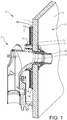
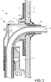
- Figs. 1 and 2 illustrate a lead-through assembly 1 according to an embodiment of the present invention.
- the lead-through assembly 1 is adapted to provide a fluid communication through the wall 5 in a direction of extension from a first side 7 of the wall 5 to a second side 9 of the wall.
- the first side 7 corresponds to an inlet side
- the second side 9 corresponds to an outlet side.
- the lead-through assembly 1 comprises a lead-through device 3.
- the lead-through device 3 comprises a passage portion 11 which extends through an opening in the wall 5 to the second side 9 of the wall 5 and is adapted to provide the fluid communication.
- the lead-through assembly 1 comprises a mounting bracket 13 to which the lead-through device 3 is attached such that the passage portion 11 extends through an opening of the mounting bracket 13.
- the mounting bracket 13 comprises support sections 14.
- the support sections 14 comprise an abutment surface 16.
- the abutment surface 16 abuts a surface 17 of the first side 7 of the wall 5, referred to as the first wall surface 17.
- the lead-through assembly 1 further comprises a retainer 19 attached to the passage portion 11 of the lead-through device 3 from the second side 9 of the wall 5.
- the retainer 19 comprises a contact surface 21 which abuts a surface 23 on the second side 9 of the wall 5, referred to as the second wall surface 23, when the retainer is attached to the passage portion 11.
- the lead-through assembly 1 is fixed in the wall by means of clamping.
- the wall 5 is clamped between the abutment surface 16 of the support section 14 and the contact surface 23 of the retainer 19.
- Support is provided by the mounting bracket 13, being located on the first side 7 of the wall 5, for the retainer 19 to press against from the second side 9 of the wall 5.
- the lead-through assembly 1 is particularly useful when the wall 5 in which the lead-through device 3 is installed is for example a single wallboard of some kind, not being able to support an installation on its own.
- the lead-through device 3 in Fig. 1 is of a wall bend fixture type, and in Fig. 2 the lead-through device 3 is illustrated with a pipe assembly 25 arranged through the same.
- the lead-through device may alternatively be of a wall box type in which case a pipe assembly is connected to the wall box on the first side of the wall.
- the abutment surface 16, and thus the mounting bracket 13 in the embodiment of the lead-through assembly 1 illustrated in Figs. 1 and 2 is secured to the first wall surface 17.
- the abutment surface 16 is secured by securing means extending in a direction from the second side 9 of the wall 5 and through the wall 5.
- Securing means may e.g. be screws or nails.
- the securing means are not illustrated in the Figs.
- the lead-through assembly 1 may be mounted in the wall 5 from the second side 9 of the wall 5.
- the second side 9 of the wall 5 typically faces a wet space, and thus installation may be facilitated by providing easy access and available space for mounting activity.
- the abutments surface is secured by means of an adhesive, e.g. by gluing.
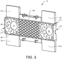
- Fig. 3 shows the mounting bracket 13.
- the mounting bracket 13 comprises two receiving sections 27, 29 for receiving a lead-through device respectively.
- the receiving sections 27, 29 each comprise an opening 31, 32 for a passage portion of each lead-through device to extend through.
- a mounting bracket and thus lead- through assembly may be adapted for any number of lead-through devices, for example one or four lead-through devices. Hence, the size of the mounting bracket would be adjusted accordingly.
- the mounting bracket 13 further comprises five support sections 14a,..,14e, which, as illustrated, are located around a periphery of the receiving section 27, 29.
- the support sections 14a,.., 14e comprise the abutment surface, each support section 14a, .., 14e comprises a portion of the abutment surface 16.
- At least one of the support sections of the mounting bracket is selectively removable.
- the location, or extension, of the abutment surface is adjustable depending on available space for installation/mounting.
- an indication of fracture 35 extending along the interface between a receiving section 29 and support section 14c may serve as a break off zone for selectively removing the support section 14c. Any other support section may be selectively removable in a similar manner.
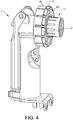
- Fig. 4 illustrates the lead-through device 3 of the arrangement in Figs. 1 and 2 .
- the lead-through device 3 comprises the passage portion 11 which is to be arranged through the opening of the receiving section of the mounting bracket and further through an opening in the wall.
- the lead-through device 3 comprises snap-lock means 37 spaced apart along a periphery which matches corresponding snap-lock means 39 of the receiving section of the mounting bracket 3, see Fig. 3 .
- the lead-through device 3 is attached to the mounting bracket 13 with a snap-lock connection.
- a lead-through device 3 may be mounted in the wall, with or without a mounting bracket 13.
- the lead-through device 3 comprises the at least one support section 14' and abutment surface 16', see Fig. 4 .
- the abutment surface 16' in the shown embodiment forms an annular-shaped surface extending radially from the periphery of the passage portion 11 in Fig.4 .
- the at least one support section 14' and abutment surface 16' may however be adapted in size and/or shape and thus being adapted depending on e.g. available space for the installation and the wall material into which the lead-through assembly will be installed.
- a lead-through device 3 as described herein may comprise an abutments surface 16' adapted to directly abut a first wall surface 17 and/or adapted to abut a surface of a mounting bracket 13, when being attached to one, as described herein, further detailed below.
- the mounting bracket 13 with the lead-through device 3 attached is illustrated.
- the mounting bracket 13 and lead-through device 3 is shown as secured to the wall 5.
- the wall 5 is illustrated as see-through making the abutment surface portions of the support section 14a, ..,14e visible in Fig. 5b .
- the abutment surface portions 16a,.., 16e of the support sections 14a, ..,14e abut a first wall surface 17 when the passage portion 11 extends through the opening to the second side 9 of the wall 5.
- the mounting bracket 13 is secured to the wall 5 such that the passage portion 11 is held in position while the retainer is attached.
- the mounting bracket 13 may be secured by securing means, e.g. screws or nails, extending in a direction from the second side 9 of the wall 5 and through the wall 5.
- the support sections 14a, .., 14e provide attachment zones for the securing means.
- Each support section 14a,.., 14e is in the shown embodiment designed so as to provide a linear screen pattern, or a raster, extending over the main area of the support sections, see Fig. 5b for example.
- the cross-section of the support sections in Figs. 1 and 2 also show the design of the abutment surface 16.
- the abutment surface 16 may be seen as being interrupted by a plurality of grooves 18.
- the grooves extend along an extension of the abutment surface 16 and parallel to each other, thus spaced apart in a regular pattern.
- the pattern of grooves provides attachment for a securing means as well as reduces the weight of the mounting bracket. In this way an attachment zone is provided that extends over the complete, or substantially the complete extension of the support section 14a,.., 14e in a plane parallel to the first wall surface 17.
- the abutment surface may also be designed in alternative ways. Purely by way of example, the abutment surface may be coherent, without being interrupted.
- a securing means such as a screw or nail, may be inserted at any position within the perimeter of each support section 14a,.., 14e. Thereby, the abutment surface 16 will be secured abutting the first wall surface 17.
- the passage portion 11 of the lead-through device 3 comprises a female, i.e. internal, threaded section 41, which is adapted to receive a male, i.e. external, threaded section 43 of the retainer 19, see Figs. 6 and 7 .
- the retainer 19 is attached by a threaded connection to the passage portion 11 of the lead-through device 3, and thereby clamps the lead-through device 3 to the wall 5.
- Figs. 1 and 2 Fig. 7 illustrates the parts of the arrangement prior to being mounted.
- the retainer 19 may be attached to the lead through device 3 using attachment means in the form of a threaded connection.
- the threaded connection may be reversed such that the passage portion 11 comprises the male threaded section and the retainer comprises the female threaded connection. It is further envisaged that other connections means are used to attach the retainer to the lead-through device.
- the passage portion 11 is illustrated as extending past the wall 5 to the second side 9.
- the length of the passage portion 11 and thus, to which extent it protrudes through the opening is selectable.
- the retainer 19 comprises the male threaded section 43
- its longitudinal extension may easily be adapted correspondingly to reach the passage portion 11. This is advantageous since the attachment position for the retainer to the passage portion, may be selectable along a direction of the longitudinal extension of the opening 31, 32 in the wall 5, without having to modify or change the opening 31, 32 in the wall, since the opening 31, 32 is adapted to receive the passage portion 11.
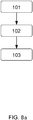
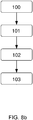
- Fig. 8a discloses a method for mounting a lead-through assembly 1 in a wall 5 as described herein.
- the lead-through assembly 1 is adapted to provide a fluid communication through the wall 5 in a direction of extension from a first side 7 of the wall 5 to a second side 9 of the wall 5.
- the lead-through assembly 1 comprises:
- the lead-through assembly 1 may comprise a mounting bracket 13, see for example Figs. 1 and 2 .
- the mounting bracket 13 is adapted to receive the lead-through device 3 such that the passage portion 11 extends through an opening in the mounting bracket 13 and the mounting bracket 13 also comprises the at least one support section 14 in this case.
- a method as recited above may comprise:
- the at least one support section 14 may be secured to the first wall surface 17 before or after attachment of the lead-through device 3 to the mounting bracket 13 and arranging of the passage portion 11 through the opening in the wall 5.
- a method as recited above comprising the use of a mounting bracket implies a mounting of a lead-through device in which additional support is provided by the at least one support section of the mounting bracket and fixing of the lead-through device in the wall is achieved by clamping the lead-through device to the wall by means of the retainer. In this way, the mounting of the lead-through device is substantially independent of the supporting capability of the wall construction itself.
- the method comprising the use of a mounting bracket is advantageous for a wall construction comprising a single wallboard, e.g. plasterboard.
- the mounting bracket provides the desired stability so that the lead-through device can be clamped to the wall by the retainer.
- the method may comprise securing the at least one support section 14, 14' to the first wall surface 17 by securing means extending in a direction from the second side 9 of the wall 5 and through the wall 5.
- the securing means are installed directly through wall without any intermediate step of providing a guiding element, such as a plate, a washer or similar part, situated on the second wall surface.
- a guiding element such as a plate, a washer or similar part
- a guiding element for the insertion of the securing means such as a plate, washer or similar, in a method or assembly as described herein, if deemed desirable.
- the method may also comprise adjusting the length of the passage portion that extends past the opening in the wall. Adjusting the length may be carried out after securing the mounting bracket to the first side of the wall.
Landscapes
- Engineering & Computer Science (AREA)
- General Engineering & Computer Science (AREA)
- Mechanical Engineering (AREA)
- Health & Medical Sciences (AREA)
- Life Sciences & Earth Sciences (AREA)
- Hydrology & Water Resources (AREA)
- Public Health (AREA)
- Water Supply & Treatment (AREA)
- Finishing Walls (AREA)
- Connection Of Plates (AREA)
Applications Claiming Priority (1)
| Application Number | Priority Date | Filing Date | Title |
|---|---|---|---|
| SE1950052A SE544355C2 (en) | 2019-01-16 | 2019-01-16 | Method and assembly for mounting a lead-through assembly in a wall |
Publications (3)
| Publication Number | Publication Date |
|---|---|
| EP3683368A1 true EP3683368A1 (de) | 2020-07-22 |
| EP3683368C0 EP3683368C0 (de) | 2023-06-07 |
| EP3683368B1 EP3683368B1 (de) | 2023-06-07 |
Family
ID=69167646
Family Applications (1)
| Application Number | Title | Priority Date | Filing Date |
|---|---|---|---|
| EP20151589.7A Active EP3683368B1 (de) | 2019-01-16 | 2020-01-14 | Verfahren und anordnung zur montage einer durchführungsvorrichtung in einer wand |
Country Status (2)
| Country | Link |
|---|---|
| EP (1) | EP3683368B1 (de) |
| SE (1) | SE544355C2 (de) |
Citations (5)
| Publication number | Priority date | Publication date | Assignee | Title |
|---|---|---|---|---|
| EP2014838A2 (de) * | 2007-07-03 | 2009-01-14 | Villeroy & Boch Gustavsberg AB | Rohreinführungselement zum Einsetzen von Wasserleitungen durch eine Wand |
| DE202009007862U1 (de) * | 2009-05-28 | 2009-09-17 | Scherer, Norbert | Universalanschlussfitting |
| EP2269754A2 (de) * | 2009-07-03 | 2011-01-05 | Villeroy & Boch Gustavsberg AB | Schneidewerkzeug für Gewinderohre |
| EP2525000A1 (de) * | 2011-05-19 | 2012-11-21 | Somatherm | Device for attaching a pipe fitting to a wall |
| FR3047751A3 (fr) * | 2016-02-12 | 2017-08-18 | Tiemme Raccorderie S P A | Dispositf pour le montage et le raccordement d un article sanitaire a une paroi |
Family Cites Families (2)
| Publication number | Priority date | Publication date | Assignee | Title |
|---|---|---|---|---|
| FR2944851B1 (fr) * | 2009-04-28 | 2015-10-16 | Somatherm | Systeme de fixation d'un raccord pour conduite de transport de fluide sur une cloison. |
| NO3026182T3 (de) * | 2014-11-28 | 2018-06-02 |
-
2019
- 2019-01-16 SE SE1950052A patent/SE544355C2/en unknown
-
2020
- 2020-01-14 EP EP20151589.7A patent/EP3683368B1/de active Active
Patent Citations (5)
| Publication number | Priority date | Publication date | Assignee | Title |
|---|---|---|---|---|
| EP2014838A2 (de) * | 2007-07-03 | 2009-01-14 | Villeroy & Boch Gustavsberg AB | Rohreinführungselement zum Einsetzen von Wasserleitungen durch eine Wand |
| DE202009007862U1 (de) * | 2009-05-28 | 2009-09-17 | Scherer, Norbert | Universalanschlussfitting |
| EP2269754A2 (de) * | 2009-07-03 | 2011-01-05 | Villeroy & Boch Gustavsberg AB | Schneidewerkzeug für Gewinderohre |
| EP2525000A1 (de) * | 2011-05-19 | 2012-11-21 | Somatherm | Device for attaching a pipe fitting to a wall |
| FR3047751A3 (fr) * | 2016-02-12 | 2017-08-18 | Tiemme Raccorderie S P A | Dispositf pour le montage et le raccordement d un article sanitaire a une paroi |
Also Published As
| Publication number | Publication date |
|---|---|
| EP3683368C0 (de) | 2023-06-07 |
| SE544355C2 (en) | 2022-04-19 |
| EP3683368B1 (de) | 2023-06-07 |
| SE1950052A1 (en) | 2020-07-17 |
Similar Documents
| Publication | Publication Date | Title |
|---|---|---|
| US20220364348A1 (en) | Pipe Connector | |
| US7109418B2 (en) | Adapter for mounting a faceplate of a first style on to an electrical outlet cavity of a second style | |
| CA2545799C (en) | Electrical ceiling box for fixture support | |
| US20150026946A1 (en) | Modular Plumbing Panel and Method of Installation | |
| US9650766B2 (en) | Plumbing outlet box with integrated mounting features | |
| AU2015202798B2 (en) | Plumbing outlet box with mounting features | |
| US20130071179A1 (en) | Fastening Device for Attachment to a Mounting Rail | |
| US9388555B2 (en) | Plumbing outlet box with integrated mounting features | |
| KR20180126973A (ko) | 건축 슬래브용 인서트 | |
| US7374057B2 (en) | Electrical junction assemblies for coupling electrical fixtures to suspended ceiling grids | |
| US20110025046A1 (en) | Device for mounting and connecting sanitary equipment pipes provided being a wall and corresponding method | |
| EP3683368B1 (de) | Verfahren und anordnung zur montage einer durchführungsvorrichtung in einer wand | |
| CA2892865C (en) | Plumbing outlet box with mounting features | |
| US6641278B1 (en) | Lighting fixture attachment means | |
| KR100393413B1 (ko) | 입상관 고정구 | |
| EP3889364A1 (de) | Adapter zur montage einer durchführungsvorrichtung und einer kupplungsanordnung an einer wandplatte | |
| WO2001001033A1 (en) | Fixture slide support with variations | |
| EP3021440B1 (de) | Verbindungsvorrichtung für eine elektrische vorrichtung | |
| KR102690344B1 (ko) | 매립박스를 이용한 높은 호환성을 가진 브라켓 | |
| US20250392108A1 (en) | Electrical box cover | |
| EP3683369B1 (de) | Wandbiegehalterung und wandbiegehalterungsanordnung | |
| US20070151972A1 (en) | Electrical box extender | |
| AU2016201266B2 (en) | Plumbing outlet box with integrated mounting features | |
| EP1048794A1 (de) | Wasserhahnbefestigungsstruktur |
Legal Events
| Date | Code | Title | Description |
|---|---|---|---|
| PUAI | Public reference made under article 153(3) epc to a published international application that has entered the european phase |
Free format text: ORIGINAL CODE: 0009012 |
|
| STAA | Information on the status of an ep patent application or granted ep patent |
Free format text: STATUS: THE APPLICATION HAS BEEN PUBLISHED |
|
| AK | Designated contracting states |
Kind code of ref document: A1 Designated state(s): AL AT BE BG CH CY CZ DE DK EE ES FI FR GB GR HR HU IE IS IT LI LT LU LV MC MK MT NL NO PL PT RO RS SE SI SK SM TR |
|
| AX | Request for extension of the european patent |
Extension state: BA ME |
|
| STAA | Information on the status of an ep patent application or granted ep patent |
Free format text: STATUS: REQUEST FOR EXAMINATION WAS MADE |
|
| 17P | Request for examination filed |
Effective date: 20210121 |
|
| RBV | Designated contracting states (corrected) |
Designated state(s): AL AT BE BG CH CY CZ DE DK EE ES FI FR GB GR HR HU IE IS IT LI LT LU LV MC MK MT NL NO PL PT RO RS SE SI SK SM TR |
|
| GRAP | Despatch of communication of intention to grant a patent |
Free format text: ORIGINAL CODE: EPIDOSNIGR1 |
|
| STAA | Information on the status of an ep patent application or granted ep patent |
Free format text: STATUS: GRANT OF PATENT IS INTENDED |
|
| INTG | Intention to grant announced |
Effective date: 20220518 |
|
| RIN1 | Information on inventor provided before grant (corrected) |
Inventor name: RYDETORP, BJOERN Inventor name: OLSSON, KRISTIAN Inventor name: CANI, PAER |
|
| GRAJ | Information related to disapproval of communication of intention to grant by the applicant or resumption of examination proceedings by the epo deleted |
Free format text: ORIGINAL CODE: EPIDOSDIGR1 |
|
| STAA | Information on the status of an ep patent application or granted ep patent |
Free format text: STATUS: REQUEST FOR EXAMINATION WAS MADE |
|
| INTC | Intention to grant announced (deleted) | ||
| GRAP | Despatch of communication of intention to grant a patent |
Free format text: ORIGINAL CODE: EPIDOSNIGR1 |
|
| STAA | Information on the status of an ep patent application or granted ep patent |
Free format text: STATUS: GRANT OF PATENT IS INTENDED |
|
| INTG | Intention to grant announced |
Effective date: 20221102 |
|
| GRAS | Grant fee paid |
Free format text: ORIGINAL CODE: EPIDOSNIGR3 |
|
| GRAA | (expected) grant |
Free format text: ORIGINAL CODE: 0009210 |
|
| STAA | Information on the status of an ep patent application or granted ep patent |
Free format text: STATUS: THE PATENT HAS BEEN GRANTED |
|
| AK | Designated contracting states |
Kind code of ref document: B1 Designated state(s): AL AT BE BG CH CY CZ DE DK EE ES FI FR GB GR HR HU IE IS IT LI LT LU LV MC MK MT NL NO PL PT RO RS SE SI SK SM TR |
|
| REG | Reference to a national code |
Ref country code: GB Ref legal event code: FG4D |
|
| REG | Reference to a national code |
Ref country code: CH Ref legal event code: EP Ref country code: AT Ref legal event code: REF Ref document number: 1575391 Country of ref document: AT Kind code of ref document: T Effective date: 20230615 |
|
| REG | Reference to a national code |
Ref country code: DE Ref legal event code: R096 Ref document number: 602020011420 Country of ref document: DE |
|
| U01 | Request for unitary effect filed |
Effective date: 20230607 |
|
| U07 | Unitary effect registered |
Designated state(s): AT BE BG DE DK EE FI FR IT LT LU LV MT NL PT SE SI Effective date: 20230612 |
|
| REG | Reference to a national code |
Ref country code: NO Ref legal event code: T2 Effective date: 20230607 |
|
| REG | Reference to a national code |
Ref country code: LT Ref legal event code: MG9D |
|
| PG25 | Lapsed in a contracting state [announced via postgrant information from national office to epo] |
Ref country code: ES Free format text: LAPSE BECAUSE OF FAILURE TO SUBMIT A TRANSLATION OF THE DESCRIPTION OR TO PAY THE FEE WITHIN THE PRESCRIBED TIME-LIMIT Effective date: 20230607 |
|
| PG25 | Lapsed in a contracting state [announced via postgrant information from national office to epo] |
Ref country code: RS Free format text: LAPSE BECAUSE OF FAILURE TO SUBMIT A TRANSLATION OF THE DESCRIPTION OR TO PAY THE FEE WITHIN THE PRESCRIBED TIME-LIMIT Effective date: 20230607 Ref country code: HR Free format text: LAPSE BECAUSE OF FAILURE TO SUBMIT A TRANSLATION OF THE DESCRIPTION OR TO PAY THE FEE WITHIN THE PRESCRIBED TIME-LIMIT Effective date: 20230607 Ref country code: GR Free format text: LAPSE BECAUSE OF FAILURE TO SUBMIT A TRANSLATION OF THE DESCRIPTION OR TO PAY THE FEE WITHIN THE PRESCRIBED TIME-LIMIT Effective date: 20230908 |
|
| PG25 | Lapsed in a contracting state [announced via postgrant information from national office to epo] |
Ref country code: SK Free format text: LAPSE BECAUSE OF FAILURE TO SUBMIT A TRANSLATION OF THE DESCRIPTION OR TO PAY THE FEE WITHIN THE PRESCRIBED TIME-LIMIT Effective date: 20230607 |
|
| PG25 | Lapsed in a contracting state [announced via postgrant information from national office to epo] |
Ref country code: IS Free format text: LAPSE BECAUSE OF FAILURE TO SUBMIT A TRANSLATION OF THE DESCRIPTION OR TO PAY THE FEE WITHIN THE PRESCRIBED TIME-LIMIT Effective date: 20231007 |
|
| PG25 | Lapsed in a contracting state [announced via postgrant information from national office to epo] |
Ref country code: SM Free format text: LAPSE BECAUSE OF FAILURE TO SUBMIT A TRANSLATION OF THE DESCRIPTION OR TO PAY THE FEE WITHIN THE PRESCRIBED TIME-LIMIT Effective date: 20230607 Ref country code: SK Free format text: LAPSE BECAUSE OF FAILURE TO SUBMIT A TRANSLATION OF THE DESCRIPTION OR TO PAY THE FEE WITHIN THE PRESCRIBED TIME-LIMIT Effective date: 20230607 Ref country code: RO Free format text: LAPSE BECAUSE OF FAILURE TO SUBMIT A TRANSLATION OF THE DESCRIPTION OR TO PAY THE FEE WITHIN THE PRESCRIBED TIME-LIMIT Effective date: 20230607 Ref country code: IS Free format text: LAPSE BECAUSE OF FAILURE TO SUBMIT A TRANSLATION OF THE DESCRIPTION OR TO PAY THE FEE WITHIN THE PRESCRIBED TIME-LIMIT Effective date: 20231007 Ref country code: CZ Free format text: LAPSE BECAUSE OF FAILURE TO SUBMIT A TRANSLATION OF THE DESCRIPTION OR TO PAY THE FEE WITHIN THE PRESCRIBED TIME-LIMIT Effective date: 20230607 |
|
| U20 | Renewal fee for the european patent with unitary effect paid |
Year of fee payment: 5 Effective date: 20240117 |
|
| PG25 | Lapsed in a contracting state [announced via postgrant information from national office to epo] |
Ref country code: PL Free format text: LAPSE BECAUSE OF FAILURE TO SUBMIT A TRANSLATION OF THE DESCRIPTION OR TO PAY THE FEE WITHIN THE PRESCRIBED TIME-LIMIT Effective date: 20230607 |
|
| REG | Reference to a national code |
Ref country code: DE Ref legal event code: R097 Ref document number: 602020011420 Country of ref document: DE |
|
| PLBE | No opposition filed within time limit |
Free format text: ORIGINAL CODE: 0009261 |
|
| STAA | Information on the status of an ep patent application or granted ep patent |
Free format text: STATUS: NO OPPOSITION FILED WITHIN TIME LIMIT |
|
| 26N | No opposition filed |
Effective date: 20240308 |
|
| PG25 | Lapsed in a contracting state [announced via postgrant information from national office to epo] |
Ref country code: MC Free format text: LAPSE BECAUSE OF FAILURE TO SUBMIT A TRANSLATION OF THE DESCRIPTION OR TO PAY THE FEE WITHIN THE PRESCRIBED TIME-LIMIT Effective date: 20230607 |
|
| PG25 | Lapsed in a contracting state [announced via postgrant information from national office to epo] |
Ref country code: MC Free format text: LAPSE BECAUSE OF FAILURE TO SUBMIT A TRANSLATION OF THE DESCRIPTION OR TO PAY THE FEE WITHIN THE PRESCRIBED TIME-LIMIT Effective date: 20230607 |
|
| REG | Reference to a national code |
Ref country code: CH Ref legal event code: PL |
|
| GBPC | Gb: european patent ceased through non-payment of renewal fee |
Effective date: 20240114 |
|
| PG25 | Lapsed in a contracting state [announced via postgrant information from national office to epo] |
Ref country code: GB Free format text: LAPSE BECAUSE OF NON-PAYMENT OF DUE FEES Effective date: 20240114 |
|
| PG25 | Lapsed in a contracting state [announced via postgrant information from national office to epo] |
Ref country code: CH Free format text: LAPSE BECAUSE OF NON-PAYMENT OF DUE FEES Effective date: 20240131 |
|
| PG25 | Lapsed in a contracting state [announced via postgrant information from national office to epo] |
Ref country code: GB Free format text: LAPSE BECAUSE OF NON-PAYMENT OF DUE FEES Effective date: 20240114 Ref country code: CH Free format text: LAPSE BECAUSE OF NON-PAYMENT OF DUE FEES Effective date: 20240131 |
|
| PG25 | Lapsed in a contracting state [announced via postgrant information from national office to epo] |
Ref country code: IE Free format text: LAPSE BECAUSE OF NON-PAYMENT OF DUE FEES Effective date: 20240114 |
|
| PG25 | Lapsed in a contracting state [announced via postgrant information from national office to epo] |
Ref country code: IE Free format text: LAPSE BECAUSE OF NON-PAYMENT OF DUE FEES Effective date: 20240114 |
|
| U20 | Renewal fee for the european patent with unitary effect paid |
Year of fee payment: 6 Effective date: 20250122 |
|
| PG25 | Lapsed in a contracting state [announced via postgrant information from national office to epo] |
Ref country code: CY Free format text: LAPSE BECAUSE OF FAILURE TO SUBMIT A TRANSLATION OF THE DESCRIPTION OR TO PAY THE FEE WITHIN THE PRESCRIBED TIME-LIMIT; INVALID AB INITIO Effective date: 20200114 |
|
| PG25 | Lapsed in a contracting state [announced via postgrant information from national office to epo] |
Ref country code: HU Free format text: LAPSE BECAUSE OF FAILURE TO SUBMIT A TRANSLATION OF THE DESCRIPTION OR TO PAY THE FEE WITHIN THE PRESCRIBED TIME-LIMIT; INVALID AB INITIO Effective date: 20200114 |
|
| PG25 | Lapsed in a contracting state [announced via postgrant information from national office to epo] |
Ref country code: TR Free format text: LAPSE BECAUSE OF FAILURE TO SUBMIT A TRANSLATION OF THE DESCRIPTION OR TO PAY THE FEE WITHIN THE PRESCRIBED TIME-LIMIT Effective date: 20230607 |
|
| U20 | Renewal fee for the european patent with unitary effect paid |
Year of fee payment: 7 Effective date: 20260122 |
|
| PGFP | Annual fee paid to national office [announced via postgrant information from national office to epo] |
Ref country code: NO Payment date: 20260120 Year of fee payment: 7 |