EP3683370B1 - Armature comprenant un dispositif de fixation et procédé de fixation de l' armature à l'aide du dispositif de fixation - Google Patents
Armature comprenant un dispositif de fixation et procédé de fixation de l' armature à l'aide du dispositif de fixation Download PDFInfo
- Publication number
- EP3683370B1 EP3683370B1 EP20151500.4A EP20151500A EP3683370B1 EP 3683370 B1 EP3683370 B1 EP 3683370B1 EP 20151500 A EP20151500 A EP 20151500A EP 3683370 B1 EP3683370 B1 EP 3683370B1
- Authority
- EP
- European Patent Office
- Prior art keywords
- housing
- locking component
- pin
- fitting
- radial direction
- Prior art date
- Legal status (The legal status is an assumption and is not a legal conclusion. Google has not performed a legal analysis and makes no representation as to the accuracy of the status listed.)
- Active
Links
Images


Classifications
-
- E—FIXED CONSTRUCTIONS
- E03—WATER SUPPLY; SEWERAGE
- E03C—DOMESTIC PLUMBING INSTALLATIONS FOR FRESH WATER OR WASTE WATER; SINKS
- E03C1/00—Domestic plumbing installations for fresh water or waste water; Sinks
- E03C1/02—Plumbing installations for fresh water
- E03C1/04—Water-basin installations specially adapted to wash-basins or baths
- E03C1/0401—Fixing a tap to the sanitary appliance or to an associated mounting surface, e.g. a countertop
- E03C1/0402—Fixing a tap to the sanitary appliance or to an associated mounting surface, e.g. a countertop with mounting from only one side
-
- E—FIXED CONSTRUCTIONS
- E03—WATER SUPPLY; SEWERAGE
- E03C—DOMESTIC PLUMBING INSTALLATIONS FOR FRESH WATER OR WASTE WATER; SINKS
- E03C1/00—Domestic plumbing installations for fresh water or waste water; Sinks
- E03C1/02—Plumbing installations for fresh water
- E03C1/04—Water-basin installations specially adapted to wash-basins or baths
- E03C1/0401—Fixing a tap to the sanitary appliance or to an associated mounting surface, e.g. a countertop
Definitions
- the invention relates to a fitting according to the preamble of claim 1, and a method for attaching such a fitting.
- the fitting can be used via its fastening arrangement e.g. B. at a sanitary facility, e.g. B. a sink, a bathtub or similar.
- the fitting is in particular a mixer tap or a faucet.
- faucets are screwed to a sink or sink.
- the screw connection is usually only accessible from the underside of the sink or washbasin.
- the object of the present invention is to at least partially solve the problems mentioned with reference to the prior art.
- the attachment of a fitting should be simplified.
- the fastening arrangement comprises at least one housing and a first locking component and a second locking component.
- the locking components form a firm connection to one another at least in an axial direction.
- One of the locking components is arranged in the housing to be movable relative to the housing to create the connection of the locking components.
- At least one of the locking components has a first contact surface which is inclined relative to a radial direction (runs perpendicular to the axial direction) for contacting a second contact surface of the other locking component, wherein by moving the first contact surface (or the first locking component) relative to the second contact surface ( or the second locking component) along the radial direction, the locking components can be displaced relative to one another along the axial direction to create or release the connection.
- the locking component which is movably arranged in the housing, is arranged in a first position when the connection between the locking components is established, i.e. when the fitting is attached to, for example. B. is attached to a sanitary facility.
- the locking component which is movably arranged in the housing, is arranged in a second position when the connection between the locking components is released, i.e. when the fitting can be released from the sanitary system.
- the fitting In the first position, the fitting can no longer be moved relative to the sanitary system (compared to normal use forces occurring). This can be considered a "locked" position.
- the housing can be designed in the manner of an insert or adapter that can be used in a fitting housing.
- the first contact surface runs (in the area of contacting the second contact surface) in particular at an angle of up to 20 degrees relative to the radial direction, the angle being more than 0 degrees.
- a wedge-shaped surface can be formed, so that a movement of the first locking component along the radial direction results in a relative movement of the two locking components along the axial direction.
- the second contact surface can run parallel to the radial direction. Alternatively, it is possible for the second contact surface to also be inclined relative to the radial direction. The explanatory statements on the first contact surface apply accordingly.
- the inclination of the contact surface(s) results in the locking components being displaced along the axial direction when the contact surfaces are displaced relative to one another along the radial direction.
- only the first locking component is movable at least along the radial direction, the first locking component having the first contact surface.
- first locking component and the second locking component do not form a screw connection with one another, and are therefore not connected to one another via a thread.
- the second locking component is a pin that extends along a first axial direction to a first end and has a second contact surface pointing in an opposite second axial direction at the first end.
- the second locking component is connected to the sanitary system (but possibly to the fitting) in the installed position.
- the fitting can be arranged on the sanitary system via the connection of the first locking component to the second locking component.
- the fastening arrangement additionally comprises a fastening arrangement arranged in the housing and extending along the radial direction and rotatable about its own longitudinal axis relative to the housing Pen.
- the first locking component is movable by the pin.
- the first locking component can be pivoted about the longitudinal axis or can be displaced exclusively along the radial direction.
- the first locking component is firmly connected to the pin, so that rotation of the pin causes the first locking component to pivot.
- the pin can interact with the first locking component via a toothing, so that the first locking component can be displaced along the radial direction by rotating the pin in the housing.
- the fastening arrangement additionally comprises a pin arranged in a rotationally fixed manner in the housing.
- the first locking component can be pivoted about an axis of rotation which extends along the radial direction and is formed by this pin.
- This pin extends from a first pin end through a first opening in the first locking component to a second pin end.
- the pin arranged in the housing can interact with the housing via stop surfaces, so that rotation of the pin arranged in the housing about the axis of rotation is prevented.
- the first locking component is rotatably mounted on this pin, so that the first locking component can be pivoted relative to the pin.
- the first locking component is movable in particular between a first position and a second position, the connection being created in the first position and the connection being released in the second position.
- the fastening arrangement additionally comprises at least one spring element, wherein the first locking component can be moved into the first position by a spring force of the at least one spring element.
- the first locking component can only be pivoted against the spring force into the second position in which the connection can be released.
- the first locking component is preferably formed by two sub-components, each of which (i.e. each sub-component) can be moved between a first position and a second position.
- the at least one spring element is arranged between the sub-components, so that the spring force acts exclusively between the sub-components.
- the sub-components are pushed apart by the spring force on one side of the axis of rotation, so that the sub-components on the other side of the axis of rotation are pressed together.
- first contact surfaces are formed on each subcomponent, so that the connection can be established or released again by pivoting both subcomponents.
- the pin arranged in the housing extends into the housing with the second pin end and has a first thread on the second pin end.
- This pin can be displaced along the radial direction by screwing it to a first mating thread arranged in the housing, so that the first locking component can be fixed in a first position that creates the connection.
- the first locking component can be arranged on the second locking component, the first locking component can be pivoted into the first position and fixed in this first position by screwing the pin arranged in the housing, in particular clamped between the pin and the housing.
- the first locking component can be clamped or clamped as a result of the screwing between the first pin end of the pin arranged in the housing and the housing.
- the fastening arrangement additionally comprises at least one first friction plate which is arranged in or on the housing (e.g. on a wall of the housing) between the housing (e.g. between a wall of the housing) and the first locking component.
- the force required for pivoting the first locking component is increased by the first friction plate.
- the fastening arrangement additionally comprises a second friction plate which is arranged in the housing between the first pin end and the first locking component, wherein the second friction plate has a The force required for pivoting the first locking component is increased.
- Each friction plate is particularly z. B. can be arranged or arranged via a clip element or a hook on the respective sub-component or the first locking component.
- the friction plate has, in particular, a surface which increases the static friction between the mutually contacting surfaces (friction plate and housing; friction plate and partial component or first locking component; friction plate and pin or first pin end).
- the fastening arrangement additionally comprises a counter pin which is arranged in the housing and forms the first counter thread.
- the counter-pin extends along the radial direction and, starting from a first counter-pin end, into the housing and beyond the second pin end.
- the execution of the first counter thread on a counter pin enables the pin arranged in the housing to be secured against rotation in the housing, the counter pin being rotatable about the axis of rotation.
- the fastening arrangement additionally comprises an outer housing, which surrounds the housing in the radial direction on the outside, and a screw element (e.g. a screw).
- the counter pin has a second thread in the area of the first counter pin end.
- the screw element has a with the second thread interacting with the second thread.
- the screw element extends through the outer housing, the counter pin being screwed to the second counter thread and the one arranged above it in the housing
- Pins can be displaced along the radial direction, so that the first locking component can be fixed in a first position that creates the connection.
- the screw element is supported in particular on the outer housing in the radial direction.
- the pin arranged in the housing and, via the first pin end, also the first locking component, or the subcomponents, or the friction plate, or the friction plates, or the locking components mentioned can be displaced together, against the housing, and thereby be pressed together.
- the first locking component when the screw element is loosened, the first locking component can be pivoted relative to the housing, in particular as a result of the spring force applied by the at least one spring element. In particular, the first locking component can then be moved into a second position and back into the first position by the spring force.
- the fastening arrangement comprises at least one housing and a first locking component and a second locking component.
- One of the locking components is in the housing for generation a connection of the locking components arranged movably relative to the housing.
- At least one of the locking components has a first contact surface which is inclined relative to a radial direction for contacting a second contact surface of the other locking component, wherein by displacing the first contact surface relative to the second contact surface along the radial direction, the locking components are displaced relative to one another along the axial direction and thus create the connection.
- first primarily serve (only) to distinguish between several similar objects, sizes or processes, i.e. in particular no dependency and/or order of these objects, sizes or prescribe processes to each other. If a dependency and/or sequence is required, this is explicitly stated here or it will be obvious to the person skilled in the art when studying the specifically described embodiment. To the extent that a component can occur multiple times (“at least one”), the description can one of these components applies equally to all or part of the majority of these components, but this is not mandatory.
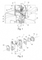
- the Fig. 1 shows a fastening arrangement 1 for a fitting 2.
- the fastening arrangement 1 comprises a housing 3 and a first locking component 4 and a second locking component 5.
- the locking components 4, 5 form a fixed connection 7 with one another with respect to an axial direction 6.
- the first locking component 4 is arranged in the housing 3 to be movable relative to the housing 3 to create the connection 7 of the locking components 4, 5.
- Both locking components 4, 5 have a first contact surface 9 which is inclined relative to a radial direction 8 (runs perpendicular to the axial direction 6) for contacting a second contact surface 10 of the other locking component 5, 4, by moving the first contact surface 9 (or the first locking component 4) relative to the second contact surface 10 (or the second locking component 5) along the radial direction 8, the locking components 4, 5 can be displaced relative to one another along the axial direction 6 to create or release the connection 7.
- the second locking component 5 is a pin that extends along a first axial direction 11 to a first end 12 and at which first end 12 has a second contact surface 10 pointing in an opposite second axial direction 13.
- the pin i.e. the second locking component 5 is connected to the sanitary system, i.e. the washbasin 39, with the first locking component 4 being connected to the fitting 2 (e.g. a faucet).
- the fitting 2 can be arranged on the sanitary system 39 via the connection 7 of the first locking component 4 with the second locking component 5.
- the pin is screwed below the washbasin 39 and extends along the first axial direction 11 through a clamping disk 38. Through the clamping disk 38 arranged on the top of the washbasin 39 and the screw connection on the underside of the washbasin 39, the pin, i.e second locking component 5, firmly connected to the washbasin 39.
- the first locking component 4 is arranged in the housing 3 (the fitting 2), with an outer housing 32 surrounding the housing 3 on an outer peripheral surface.
- Fig. 2 shows part of the fastening arrangement 1 Fig. 1 in a perspective view in an exploded view.
- Fig. 3 shows the part Fig. 2 in a first position 22 in a perspective view.
- Fig. 4 shows the part Fig. 3 in a second position 23 in a perspective view.
- Fig. 5 shows a detail of the part Fig. 2 and 3 in a perspective view.
- Fig. 6 shows the part Fig. 3 together with the second locking component 5 in a side view in a first position 22.
- the Fig. 2 to 6 are described together below. Onto the statements Fig. 1 is referred.
- the fastening arrangement 1 additionally comprises a pin 16 arranged in a rotationally fixed manner in the housing 3.
- the first locking component 4 can be pivoted about an axis of rotation 17 which extends along the radial direction 8 and is formed by the pin 16.
- the pin 16 extends from a first pin end 18 through a first opening 19 of the first locking component 4 to a second pin end 20.
- the pin 16 interacts with the housing 3 via stop surfaces 40, so that rotation of the pin 16 about the axis of rotation 17 is prevented.
- the first locking component 4 is rotatably mounted on the pin 16, so that the first locking component 4 can be pivoted relative to the pin 16.
- the first locking component 4 is between a first position 22 ( Fig. 3 ) and a second position ( Fig. 4 ) movable, the connection 7 being created in the first position 22 and the connection 7 being released in the second position 23.
- the fastening arrangement 1 additionally comprises a spring element 21, wherein the first locking component 4 can be moved into the first position 22 by a spring force 24 of the spring element 21. The first locking component 4 can therefore only be pivoted against the spring force 24 into the second position 23, in which the connection 7 can be released.
- the first locking component 4 is formed by two sub-components 25, each of which (i.e. each sub-component 25) can be moved between a first position 22 and a second position 23.
- the spring element 21 is arranged between the sub-components 25, so that the spring force 24 acts exclusively between the sub-components 25.
- the sub-components 25 are therefore pushed apart by the spring force 24 on one side of the axis of rotation 17, so that the sub-components 25 on the other side of the Axis of rotation 17 (for creating the connection 7 via the contact surfaces 9, 10; see Fig. 6 ) are pressed together.
- the pin 16 extends (further) into the housing 3 with the second pin end 20 along the radial direction 8 and has a first thread 26 on the second pin end 20.
- the pin 16 is screwed to a first counter thread 27 arranged in the housing 3 (see Fig. 7 to 12 ) can be displaced along the radial direction 8, so that the first locking component 4 can be fixed in a first position 22 which creates the connection 7.
- the first locking component 4 can be arranged on the second locking component 5, which is pivoted into the first position 22 and fixed in this first position 22 by screwing the pin 16, here by clamping between the pin 16 and the housing 3.
- the fastening arrangement 1 additionally comprises a first friction plate 28 and a second friction plate 29, which are in or on the housing 3 (here in each case on a wall of the housing 3) between the housing 3 (e.g. between a wall of the housing 3) and the first locking component 4 is arranged (see Fig. 7 to 12 ).
- the friction plates 28, 29 increase the force required for pivoting the first locking component 4.
- Each friction plate 28, 29 is arranged via a clip element or via a hook on the respective sub-component 25 or the first locking component 4.
- the friction plates 28, 29 have a static friction between the mutually contacting surfaces (friction plate 28, 29 and housing 3; friction plate 28, 29 and Subcomponent 25 or first locking component 4; Friction plate 28 and pin 16 or first pin end 18) increasing surface.
- Fig. 7 shows part of the fastening arrangement 1 Fig. 1 in a perspective view in section in an exploded view.
- Fig. 8 shows the part Fig. 7 in a perspective view in section.
- Fig. 9 shows the part Fig. 8 in a side view in section.
- Fig. 10 shows the part 8 and 9 with an outer housing 32 in a perspective view in section.
- Fig. 11 shows the part Fig. 10 in a side view in section.
- Fig. 12 shows the fastening arrangement 1 Fig. 1 before connecting in a perspective view.
- the Fig. 7 to 12 are described together below. On the comments on the Fig. 2 to 6 is referred.
- the fastening arrangement 1 additionally includes a counter pin 30, which is arranged in the housing 3 and forms the first counter thread 27.
- the counter pin 30 extends along the radial direction 8 and, starting from a first counter pin end 31, into the housing 3 up to beyond the second pin end 20 of the pin 16.
- the execution of the first counter thread 27 on a counter pin 30 enables the pin 16 to be secured in or on the housing 3 against rotation, with the counter pin 30 being rotatable about the axis of rotation 17.
- the fastening arrangement 1 additionally includes an outer housing 32, which surrounds the housing 3 on the outside in the radial direction 8, and a screw element 33 (here a screw).
- the counter pin 30 has a second thread 34 in the area of the first counter pin end 31.
- the screw element 33 has a second counter-thread 35 which interacts with the second thread 34 on.
- the screw element 33 extends through the outer housing 32, with the counter pin 30 and above the pin 16 being displaceable along the radial direction 8 by screwing with the second counter thread 35, so that the first locking component 4 is in a first position producing the connection 7 22 can be fixed.
- the screw element 33 is supported on the outer housing 32 in relation to the radial direction 8.
- the pin 16 and, via the first pin end 18, also the first locking component 4, or the sub-components 25, or the friction plates 28, 29, or the locking components mentioned can be moved together, against the housing 3, and thereby be pressed together.
- the first locking component 4 can thus be fixed in a first position 22 which creates the connection 7, so that the fitting 2 is firmly connected to the sanitary system, here to the washbasin 39.
- the first locking component 4 When the screw element 33 is loosened, the first locking component 4 can be pivoted relative to the housing 3, in particular against the spring force 24 applied by the one spring element 21. In particular, the first locking component 4 can then be moved into a second position 23 and back into it by the spring force 24 first position 22 can be moved.
- Fig. 13 shows a first embodiment variant of the fastening arrangement 1 in a perspective view in section.
- Fig. 14 shows the fastening arrangement 1 Fig. 13 in a second position 23 in a side view.
- Fig. 15 shows the fastening arrangement 1 Fig. 13 in a first position 22 in a side view.
- the Fig. 13 to 16 are described together below.
- the fastening arrangement 1 comprises a housing 3 and a first locking component 4 and a second locking component 5.
- the locking components 4, 5 form a fixed connection 7 with one another with respect to an axial direction 6.
- the first locking component 4 is arranged in the housing 3 to be movable relative to the housing 3 to create the connection 7 of the locking components 4, 5.
- Both locking components 4, 5 have a first contact surface 9 which is inclined relative to a radial direction 8 (runs perpendicular to the axial direction 6) for contacting a second contact surface 10 of the other locking component 5, 4, by moving the first contact surface 9 ( or the first locking component 4) relative to the second contact surface 10 (or the second locking component 5) along the radial direction 8, the locking components 4, 5 can be displaced relative to one another along the axial direction 6 to create or release the connection 7.
- the second locking component 5 is a pin that extends along a first axial direction 11 to a first end 12 and has a second contact surface 10 pointing in an opposite second axial direction 13 at the first end 12.
- the pin i.e. the second locking component 5 is connected to the sanitary system, i.e. the washbasin 39 (not shown here), with the first locking component 4 being connected to the fitting 2 (e.g. a faucet).
- the pin is z. B. screwed below the sink 39 and extends along the first axial direction 11 through a clamping disk 38 (not shown here). Through the clamping disk 38 arranged on the top of the washbasin 39 and the screw connection on the underside of the washbasin 39, the pin, i.e. the second locking component 5, firmly connected to the washbasin 39 (see, for example, Fig. 1 ).
- a guide element 37 arranged in the housing 3 is provided, through which the fitting 2 can be centered relative to the second locking component 5.
- the fastening arrangement 1 additionally comprises a pin 15 which is arranged in the housing 3 and extends along the radial direction 8 and can be rotated about its own longitudinal axis 14 relative to the housing 3.
- the first locking component 4 can be moved by the pin 15.
- the first locking component 4 can be pivoted about the longitudinal axis 14.
- the first locking component 4 can be fixed in a second position 23 via a retaining spring 36. By rotating the pin 15, the first locking component 4 can be pivoted out of the second position 23 and into the first position 22, so that the connection 7 between the second locking component 5 (the pin) and the first locking component 4 is established.
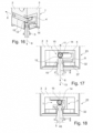
- Fig. 16 shows a second embodiment variant of the fastening arrangement 1 in a perspective view in section.
- Fig. 17 shows the fastening arrangement 1 Fig. 16 in a second position 23 in a side view.
- Fig. 18 shows the fastening arrangement 1 Fig. 16 in a first position 22 in a side view.
- the Fig. 16 to 18 are described together below. Onto the statements Fig. 13 to 15 is referred to.
- the fastening arrangement 1 also includes a pin 15 which is arranged in the housing 3 and extends along the radial direction 8 and can be rotated about its own longitudinal axis 14 relative to the housing 3.
- the pin 15 interacts with the first locking component 4 via a toothing, so that the first locking component 4 can be displaced along the radial direction 8 by rotating the pin 15 in the housing 3.
- the first locking component 4 can be displaced out of the second position 23 and into the first position 22 exclusively along the radial direction 8, so that the connection 7 between the second locking component 5 (the pin) and the first locking component 4 is made.
Landscapes
- Health & Medical Sciences (AREA)
- Life Sciences & Earth Sciences (AREA)
- Engineering & Computer Science (AREA)
- Hydrology & Water Resources (AREA)
- Public Health (AREA)
- Water Supply & Treatment (AREA)
- Connection Of Plates (AREA)
Claims (12)
- Robinetterie (2), notamment mitigeur ou robinet à eau, pourvue d'un ensemble de fixation (1) pour la fixation de la robinetterie (2) sur une installation sanitaire (39), comme par exemple un lavabo, une baignoire ou analogue, l'ensemble de fixation (1) comprenant au moins un boîtier (3), ainsi qu'un premier composant de verrouillage (4) et un deuxième composant de verrouillage (5), lesquels composants de verrouillage (4 , 5) étant susceptibles de constituer ensemble un assemblage (7) fixe au moins dans une direction (6) axiale ; pour créer l'assemblage (7) des composants de verrouillage (4, 5), l'un des composants de verrouillage (4, 5) étant placé dans le boîtier (3) en étant mobile par rapport au boîtier (3) ; au moins l'un des composants de verrouillage (4, 5) comportant une première surface de contact (9) s'étendant en inclinaison par rapport à une direction (8) radiale qui s'écoule à la perpendiculaire de la direction axiale, pour la mise en contact d'une deuxième surface de contact (10) de l'autre composant de verrouillage (5, 4), par un déplacement de la première surface de contact (9) par rapport à la deuxième surface de contact (10) le long de la direction (8) radiale, les composants de verrouillage (4, 5) étant déplaçables l'un par rapport à l'autre le long de la direction (6) axiale, pour créer ou pour désolidariser l'assemblage (7), caractérisée en ce que seul le première composant de verrouillage (4) est mobile au moins le long de la direction (8) radiale, le premier composant de verrouillage (4) comportant la première surface de contact (9) et en ce que le deuxième composant de verrouillage (5) est un tenon, qui s'étend le long d'une première direction (11) axiale, jusqu'à une première extrémité (12) et qui sur la première extrémité (12) comporte la deuxième surface de contact (10) montrant vers une deuxième direction (13) axiale opposée.
- Robinetterie (2) selon la revendication 1 du brevet, comprenant en supplément une tige (15) placée dans le boîtier (3) et s'étendant le long de la direction (8) radiale et rotative autour d'un axe longitudinal (14) propre, par rapport au boîtier (3) ; le premier composant de verrouillage (4) étant mobile par la tige (15) ; le premier composant de verrouillage (4) étant susceptible de pivoter autour de l'axe longitudinal (14) ou étant uniquement déplaçable le long de la direction (8) radiale.
- Robinetterie (2) selon la revendication 1 du brevet, comprenant en supplément un tenon (16), placé de manière solidaire en rotation dans le boîtier (3) ; le premier composant de verrouillage (4) étant susceptible de pivoter autour d'un axe de rotation (17) qui s'étend le long de la direction (8) radiale, qui est constitué par le tenon (16) placé dans le boîtier ; le tenon (16) placé dans le boîtier s'étendant à partir d'une première extrémité (18) du tenon à travers un premier orifice (19) du premier composant de verrouillage (4) jusqu'à une deuxième extrémité (20) du tenon.
- Robinetterie (2) selon la revendication 3 du brevet, comprenant en supplément au moins un élément à ressort (21) ; le premier composant de verrouillage (4) étant mobile entre une première position (22) et une deuxième position (23), dans la première position (22), l'assemblage (7) étant créé et dans la deuxième position (23), l'assemblage (7) étant désolidarisé ; le premier composant de verrouillage (4) étant mobile dans la première position (22) par une force de ressort (24) de l'au moins un élément à ressort (21).
- Robinetterie (2) selon la revendication 4 du brevet, le premier composant de verrouillage (4) étant constitué de deux composants partiels (25), dont chacun est mobile entre la première position (22) et la deuxième position (23) ; l'au moins un élément à ressort (21) étant placé entre les composants partiels (25), de telle sorte que la force de ressort (24) agisse exclusivement entre les composants partiels (25) .
- Robinetterie (2) selon l'une quelconque des revendications 3 à 5 du brevet, le tenon (16) placé dans le boîtier s'étendant avec la deuxième extrémité (20) du tenon à l'intérieur du boîtier (3) et comportant sur la deuxième extrémité (20) du tenon un premier filetage (26), le tenon (16) placé dans le boîtier étant déplaçable le long de la direction radiale (8) par un vissage avec un premier contre-filetage (27) placé dans le boîtier (3), de telle sorte que le premier composant de verrouillage (4) soit susceptible d'être fixé dans une première position (22) créant l'assemblage (7).
- Robinetterie (2) selon la revendication 6, du brevet, suite au vissage, le premier composant de verrouillage (4) étant susceptible d'être enserré entre la première extrémité (18) de tenon du tenon (16) placé dans le boîtier et le boîtier (3).
- Robinetterie (2) selon la revendication 7 du brevet, comprenant en supplément au moins une première plaque de friction (28), qui est placée dans ou sur le boîtier (3) et ainsi ente le boîtier (3) et le premier composant de verrouillage (4), par la première plaque de friction (28), une force nécessaire pour le pivotement du premier composant de verrouillage (4) étant augmentée.
- Robinetterie (2) selon la revendication 8 du brevet, comprenant en supplément une deuxième plaque de friction (29), qui est placée dans le boîtier (3) entre la première extrémité (18) de tenon du tenon (16) placé dans le boîtier et le premier composant de verrouillage (4), par la deuxième plaque de friction (29), une force nécessaire pour le pivotement du premier composant de verrouillage (4) étant augmentée.
- Robinetterie (2) selon l'une quelconque des revendications 6 à 9, comprenant en supplément un contre-tenon (30), qui est placé dans le boîtier (3) et qui constitue le premier contre-filetage (27) ; le contre-tenon (30) s'étendant le long de la direction (8) radiale et en partant d'une première extrémité (31) du contre-tenon à l'intérieur du boîtier (3) jusqu'à au-delà de la deuxième extrémité (20) du tenon.
- Robinetterie (2) selon la revendication 10 du brevet, comprenant en supplément un boîtier extérieur (32), qui entoure le boîtier (3) à l'extérieur dans la direction radiale (8), ainsi qu'un élément de vissage (33) ; dans la zone de la première extrémité (31) du contre-tenon, le contre-tenon (30) comportant un deuxième filetage (34) ; l'élément de vissage (33) comportant un deuxième contre-filetage (35) qui coopère avec le deuxième filetage (34) ; l'élément de vissage (33) s'étendant à travers le boîtier extérieur (32) et par le vissage avec le deuxième contre-filetage (35), le contre-tenon (30) et en outre le tenon (16) étant déplaçable le long de la direction (8) radiale, de telle sorte que le premier composant de verrouillage (4) soit susceptible d'être fixé dans une première position (22) créant l'assemblage (7).
- Procédé, destiné à fixer une robinetterie (2) selon la revendication 1, par un décalage de la première surface de contact (9) par rapport à la deuxième surface de contact (10) le long de la direction radiale (8), les composants de verrouillage (4, 5) étant déplacés l'un par rapport à l'autre le long de la direction axiale (6) et créant ainsi l'assemblage (7) .
Applications Claiming Priority (1)
| Application Number | Priority Date | Filing Date | Title |
|---|---|---|---|
| DE102019000317.9A DE102019000317A1 (de) | 2019-01-18 | 2019-01-18 | Befestigungsanordnung für eine Armatur und Verfahren zur Befestigung einer Armatur mit einer Befestigungsanordnung |
Publications (2)
| Publication Number | Publication Date |
|---|---|
| EP3683370A1 EP3683370A1 (fr) | 2020-07-22 |
| EP3683370B1 true EP3683370B1 (fr) | 2024-03-06 |
Family
ID=69159707
Family Applications (1)
| Application Number | Title | Priority Date | Filing Date |
|---|---|---|---|
| EP20151500.4A Active EP3683370B1 (fr) | 2019-01-18 | 2020-01-13 | Armature comprenant un dispositif de fixation et procédé de fixation de l' armature à l'aide du dispositif de fixation |
Country Status (2)
| Country | Link |
|---|---|
| EP (1) | EP3683370B1 (fr) |
| DE (1) | DE102019000317A1 (fr) |
Citations (1)
| Publication number | Priority date | Publication date | Assignee | Title |
|---|---|---|---|---|
| EP1338711A1 (fr) * | 2002-02-26 | 2003-08-27 | fischerwerke Artur Fischer GmbH & Co. KG | Dispositif de fixation d'un object à une paroi |
Family Cites Families (5)
| Publication number | Priority date | Publication date | Assignee | Title |
|---|---|---|---|---|
| US4281857A (en) * | 1979-04-12 | 1981-08-04 | Bruce Randall | Faucet connector |
| WO2002075183A2 (fr) * | 2001-03-16 | 2002-09-26 | Loren Skarie | Appareils de retenue de robinet auto-alignes |
| US7269864B2 (en) * | 2002-04-17 | 2007-09-18 | Masco Corporation Of Indiana | Mounting system for a faucet |
| US7082966B2 (en) * | 2004-12-15 | 2006-08-01 | Lian-Jie Kuo | Water-flow guide device of faucet |
| ITMI20111892A1 (it) * | 2011-10-18 | 2013-04-19 | Oberdin S R L | Dispositivo di attacco rapido per il montaggio di impianti sanitari, quali rubinetti e simili. |
-
2019
- 2019-01-18 DE DE102019000317.9A patent/DE102019000317A1/de not_active Withdrawn
-
2020
- 2020-01-13 EP EP20151500.4A patent/EP3683370B1/fr active Active
Patent Citations (1)
| Publication number | Priority date | Publication date | Assignee | Title |
|---|---|---|---|---|
| EP1338711A1 (fr) * | 2002-02-26 | 2003-08-27 | fischerwerke Artur Fischer GmbH & Co. KG | Dispositif de fixation d'un object à une paroi |
Also Published As
| Publication number | Publication date |
|---|---|
| EP3683370A1 (fr) | 2020-07-22 |
| DE102019000317A1 (de) | 2020-07-23 |
Similar Documents
| Publication | Publication Date | Title |
|---|---|---|
| EP2318723B1 (fr) | Agencement de fixation avec compensation des tolerances | |
| EP2166235B1 (fr) | Elément de liaison et procédé de fixation d'au moins deux composants l'un sur l'autre | |
| DE112017000156B4 (de) | Ein Überlochinstallationsgerät | |
| EP2803308B1 (fr) | Dispositif de fixation amovible d'un siège de toilettes et procédé correspondant | |
| DE202014102852U1 (de) | Rastarretierungsstruktur | |
| DE3127521A1 (de) | "schnellspannmutter" | |
| DE102015219175B4 (de) | Anschlussrohrstutzen für eine Sanitärarmatur | |
| EP3683370B1 (fr) | Armature comprenant un dispositif de fixation et procédé de fixation de l' armature à l'aide du dispositif de fixation | |
| EP3644807B1 (fr) | Joint rotatif de couvercle | |
| EP1586228A1 (fr) | Raccordement de fil, en particulier à l'attachement d'un outil ou d'un adapteur d'outil, à un mécanisme de prolongation | |
| DE19954922B4 (de) | Scharnier | |
| CH702050A1 (de) | Lösbare Verbindung zwischen einem Fräsbohrkopf und einer Welle. | |
| DE102011110642B4 (de) | Beschlagbaugruppe | |
| DE102021103968B3 (de) | Montage-Einheit mit zumindest einer Montageschiene sowie wenigstens einer Halteklammer | |
| EP3926185B1 (fr) | Support mural | |
| EP3763901B1 (fr) | Système de fermeture de porte | |
| DE4030765A1 (de) | Armatur | |
| CH624188A5 (en) | Device for securing a profiled shaft | |
| EP3269903B1 (fr) | Garniture à rosette pour poussoir de portes ou de fenêtres | |
| DE3019784A1 (de) | Vorrichtung zur schraubbefestigung von flachteilen | |
| DE9114220U1 (de) | Bolzen zum Verbinden zweier Bauteile | |
| DE102015116426A1 (de) | Kippdübel | |
| DE3829030A1 (de) | Verstellbare riegelvorrichtung | |
| EP1922467B1 (fr) | Charniere pour portes, fenetres ou elements similaires | |
| DE102018201186A1 (de) | Türschließsystem |
Legal Events
| Date | Code | Title | Description |
|---|---|---|---|
| PUAI | Public reference made under article 153(3) epc to a published international application that has entered the european phase |
Free format text: ORIGINAL CODE: 0009012 |
|
| STAA | Information on the status of an ep patent application or granted ep patent |
Free format text: STATUS: THE APPLICATION HAS BEEN PUBLISHED |
|
| AK | Designated contracting states |
Kind code of ref document: A1 Designated state(s): AL AT BE BG CH CY CZ DE DK EE ES FI FR GB GR HR HU IE IS IT LI LT LU LV MC MK MT NL NO PL PT RO RS SE SI SK SM TR |
|
| AX | Request for extension of the european patent |
Extension state: BA ME |
|
| STAA | Information on the status of an ep patent application or granted ep patent |
Free format text: STATUS: REQUEST FOR EXAMINATION WAS MADE |
|
| 17P | Request for examination filed |
Effective date: 20210122 |
|
| RBV | Designated contracting states (corrected) |
Designated state(s): AL AT BE BG CH CY CZ DE DK EE ES FI FR GB GR HR HU IE IS IT LI LT LU LV MC MK MT NL NO PL PT RO RS SE SI SK SM TR |
|
| STAA | Information on the status of an ep patent application or granted ep patent |
Free format text: STATUS: EXAMINATION IS IN PROGRESS |
|
| 17Q | First examination report despatched |
Effective date: 20220413 |
|
| GRAP | Despatch of communication of intention to grant a patent |
Free format text: ORIGINAL CODE: EPIDOSNIGR1 |
|
| STAA | Information on the status of an ep patent application or granted ep patent |
Free format text: STATUS: GRANT OF PATENT IS INTENDED |
|
| INTG | Intention to grant announced |
Effective date: 20231005 |
|
| GRAS | Grant fee paid |
Free format text: ORIGINAL CODE: EPIDOSNIGR3 |
|
| GRAA | (expected) grant |
Free format text: ORIGINAL CODE: 0009210 |
|
| STAA | Information on the status of an ep patent application or granted ep patent |
Free format text: STATUS: THE PATENT HAS BEEN GRANTED |
|
| AK | Designated contracting states |
Kind code of ref document: B1 Designated state(s): AL AT BE BG CH CY CZ DE DK EE ES FI FR GB GR HR HU IE IS IT LI LT LU LV MC MK MT NL NO PL PT RO RS SE SI SK SM TR |
|
| REG | Reference to a national code |
Ref country code: CH Ref legal event code: EP |
|
| REG | Reference to a national code |
Ref country code: DE Ref legal event code: R096 Ref document number: 502020007207 Country of ref document: DE |
|
| REG | Reference to a national code |
Ref country code: IE Ref legal event code: FG4D Free format text: LANGUAGE OF EP DOCUMENT: GERMAN |
|
| REG | Reference to a national code |
Ref country code: LT Ref legal event code: MG9D |
|
| PG25 | Lapsed in a contracting state [announced via postgrant information from national office to epo] |
Ref country code: LT Free format text: LAPSE BECAUSE OF FAILURE TO SUBMIT A TRANSLATION OF THE DESCRIPTION OR TO PAY THE FEE WITHIN THE PRESCRIBED TIME-LIMIT Effective date: 20240306 |
|
| REG | Reference to a national code |
Ref country code: NL Ref legal event code: MP Effective date: 20240306 |
|
| PG25 | Lapsed in a contracting state [announced via postgrant information from national office to epo] |
Ref country code: GR Free format text: LAPSE BECAUSE OF FAILURE TO SUBMIT A TRANSLATION OF THE DESCRIPTION OR TO PAY THE FEE WITHIN THE PRESCRIBED TIME-LIMIT Effective date: 20240607 |
|
| PG25 | Lapsed in a contracting state [announced via postgrant information from national office to epo] |
Ref country code: RS Free format text: LAPSE BECAUSE OF FAILURE TO SUBMIT A TRANSLATION OF THE DESCRIPTION OR TO PAY THE FEE WITHIN THE PRESCRIBED TIME-LIMIT Effective date: 20240606 Ref country code: HR Free format text: LAPSE BECAUSE OF FAILURE TO SUBMIT A TRANSLATION OF THE DESCRIPTION OR TO PAY THE FEE WITHIN THE PRESCRIBED TIME-LIMIT Effective date: 20240306 |
|
| PG25 | Lapsed in a contracting state [announced via postgrant information from national office to epo] |
Ref country code: ES Free format text: LAPSE BECAUSE OF FAILURE TO SUBMIT A TRANSLATION OF THE DESCRIPTION OR TO PAY THE FEE WITHIN THE PRESCRIBED TIME-LIMIT Effective date: 20240306 |
|
| PG25 | Lapsed in a contracting state [announced via postgrant information from national office to epo] |
Ref country code: RS Free format text: LAPSE BECAUSE OF FAILURE TO SUBMIT A TRANSLATION OF THE DESCRIPTION OR TO PAY THE FEE WITHIN THE PRESCRIBED TIME-LIMIT Effective date: 20240606 Ref country code: NO Free format text: LAPSE BECAUSE OF FAILURE TO SUBMIT A TRANSLATION OF THE DESCRIPTION OR TO PAY THE FEE WITHIN THE PRESCRIBED TIME-LIMIT Effective date: 20240606 Ref country code: LT Free format text: LAPSE BECAUSE OF FAILURE TO SUBMIT A TRANSLATION OF THE DESCRIPTION OR TO PAY THE FEE WITHIN THE PRESCRIBED TIME-LIMIT Effective date: 20240306 Ref country code: HR Free format text: LAPSE BECAUSE OF FAILURE TO SUBMIT A TRANSLATION OF THE DESCRIPTION OR TO PAY THE FEE WITHIN THE PRESCRIBED TIME-LIMIT Effective date: 20240306 Ref country code: GR Free format text: LAPSE BECAUSE OF FAILURE TO SUBMIT A TRANSLATION OF THE DESCRIPTION OR TO PAY THE FEE WITHIN THE PRESCRIBED TIME-LIMIT Effective date: 20240607 Ref country code: FI Free format text: LAPSE BECAUSE OF FAILURE TO SUBMIT A TRANSLATION OF THE DESCRIPTION OR TO PAY THE FEE WITHIN THE PRESCRIBED TIME-LIMIT Effective date: 20240306 Ref country code: ES Free format text: LAPSE BECAUSE OF FAILURE TO SUBMIT A TRANSLATION OF THE DESCRIPTION OR TO PAY THE FEE WITHIN THE PRESCRIBED TIME-LIMIT Effective date: 20240306 Ref country code: BG Free format text: LAPSE BECAUSE OF FAILURE TO SUBMIT A TRANSLATION OF THE DESCRIPTION OR TO PAY THE FEE WITHIN THE PRESCRIBED TIME-LIMIT Effective date: 20240306 |
|
| PG25 | Lapsed in a contracting state [announced via postgrant information from national office to epo] |
Ref country code: SE Free format text: LAPSE BECAUSE OF FAILURE TO SUBMIT A TRANSLATION OF THE DESCRIPTION OR TO PAY THE FEE WITHIN THE PRESCRIBED TIME-LIMIT Effective date: 20240306 Ref country code: LV Free format text: LAPSE BECAUSE OF FAILURE TO SUBMIT A TRANSLATION OF THE DESCRIPTION OR TO PAY THE FEE WITHIN THE PRESCRIBED TIME-LIMIT Effective date: 20240306 |
|
| PG25 | Lapsed in a contracting state [announced via postgrant information from national office to epo] |
Ref country code: NL Free format text: LAPSE BECAUSE OF FAILURE TO SUBMIT A TRANSLATION OF THE DESCRIPTION OR TO PAY THE FEE WITHIN THE PRESCRIBED TIME-LIMIT Effective date: 20240306 |
|
| PG25 | Lapsed in a contracting state [announced via postgrant information from national office to epo] |
Ref country code: NL Free format text: LAPSE BECAUSE OF FAILURE TO SUBMIT A TRANSLATION OF THE DESCRIPTION OR TO PAY THE FEE WITHIN THE PRESCRIBED TIME-LIMIT Effective date: 20240306 |
|
| PG25 | Lapsed in a contracting state [announced via postgrant information from national office to epo] |
Ref country code: IS Free format text: LAPSE BECAUSE OF FAILURE TO SUBMIT A TRANSLATION OF THE DESCRIPTION OR TO PAY THE FEE WITHIN THE PRESCRIBED TIME-LIMIT Effective date: 20240706 |
|
| PG25 | Lapsed in a contracting state [announced via postgrant information from national office to epo] |
Ref country code: PT Free format text: LAPSE BECAUSE OF FAILURE TO SUBMIT A TRANSLATION OF THE DESCRIPTION OR TO PAY THE FEE WITHIN THE PRESCRIBED TIME-LIMIT Effective date: 20240708 Ref country code: SM Free format text: LAPSE BECAUSE OF FAILURE TO SUBMIT A TRANSLATION OF THE DESCRIPTION OR TO PAY THE FEE WITHIN THE PRESCRIBED TIME-LIMIT Effective date: 20240306 |
|
| PG25 | Lapsed in a contracting state [announced via postgrant information from national office to epo] |
Ref country code: EE Free format text: LAPSE BECAUSE OF FAILURE TO SUBMIT A TRANSLATION OF THE DESCRIPTION OR TO PAY THE FEE WITHIN THE PRESCRIBED TIME-LIMIT Effective date: 20240306 Ref country code: CZ Free format text: LAPSE BECAUSE OF FAILURE TO SUBMIT A TRANSLATION OF THE DESCRIPTION OR TO PAY THE FEE WITHIN THE PRESCRIBED TIME-LIMIT Effective date: 20240306 |
|
| PG25 | Lapsed in a contracting state [announced via postgrant information from national office to epo] |
Ref country code: PL Free format text: LAPSE BECAUSE OF FAILURE TO SUBMIT A TRANSLATION OF THE DESCRIPTION OR TO PAY THE FEE WITHIN THE PRESCRIBED TIME-LIMIT Effective date: 20240306 |
|
| PG25 | Lapsed in a contracting state [announced via postgrant information from national office to epo] |
Ref country code: SK Free format text: LAPSE BECAUSE OF FAILURE TO SUBMIT A TRANSLATION OF THE DESCRIPTION OR TO PAY THE FEE WITHIN THE PRESCRIBED TIME-LIMIT Effective date: 20240306 |
|
| PG25 | Lapsed in a contracting state [announced via postgrant information from national office to epo] |
Ref country code: SM Free format text: LAPSE BECAUSE OF FAILURE TO SUBMIT A TRANSLATION OF THE DESCRIPTION OR TO PAY THE FEE WITHIN THE PRESCRIBED TIME-LIMIT Effective date: 20240306 Ref country code: SK Free format text: LAPSE BECAUSE OF FAILURE TO SUBMIT A TRANSLATION OF THE DESCRIPTION OR TO PAY THE FEE WITHIN THE PRESCRIBED TIME-LIMIT Effective date: 20240306 Ref country code: RO Free format text: LAPSE BECAUSE OF FAILURE TO SUBMIT A TRANSLATION OF THE DESCRIPTION OR TO PAY THE FEE WITHIN THE PRESCRIBED TIME-LIMIT Effective date: 20240306 Ref country code: PT Free format text: LAPSE BECAUSE OF FAILURE TO SUBMIT A TRANSLATION OF THE DESCRIPTION OR TO PAY THE FEE WITHIN THE PRESCRIBED TIME-LIMIT Effective date: 20240708 Ref country code: PL Free format text: LAPSE BECAUSE OF FAILURE TO SUBMIT A TRANSLATION OF THE DESCRIPTION OR TO PAY THE FEE WITHIN THE PRESCRIBED TIME-LIMIT Effective date: 20240306 Ref country code: IS Free format text: LAPSE BECAUSE OF FAILURE TO SUBMIT A TRANSLATION OF THE DESCRIPTION OR TO PAY THE FEE WITHIN THE PRESCRIBED TIME-LIMIT Effective date: 20240706 Ref country code: EE Free format text: LAPSE BECAUSE OF FAILURE TO SUBMIT A TRANSLATION OF THE DESCRIPTION OR TO PAY THE FEE WITHIN THE PRESCRIBED TIME-LIMIT Effective date: 20240306 Ref country code: CZ Free format text: LAPSE BECAUSE OF FAILURE TO SUBMIT A TRANSLATION OF THE DESCRIPTION OR TO PAY THE FEE WITHIN THE PRESCRIBED TIME-LIMIT Effective date: 20240306 |
|
| PG25 | Lapsed in a contracting state [announced via postgrant information from national office to epo] |
Ref country code: IT Free format text: LAPSE BECAUSE OF FAILURE TO SUBMIT A TRANSLATION OF THE DESCRIPTION OR TO PAY THE FEE WITHIN THE PRESCRIBED TIME-LIMIT Effective date: 20240306 |
|
| REG | Reference to a national code |
Ref country code: DE Ref legal event code: R097 Ref document number: 502020007207 Country of ref document: DE |
|
| PG25 | Lapsed in a contracting state [announced via postgrant information from national office to epo] |
Ref country code: IT Free format text: LAPSE BECAUSE OF FAILURE TO SUBMIT A TRANSLATION OF THE DESCRIPTION OR TO PAY THE FEE WITHIN THE PRESCRIBED TIME-LIMIT Effective date: 20240306 |
|
| PLBE | No opposition filed within time limit |
Free format text: ORIGINAL CODE: 0009261 |
|
| STAA | Information on the status of an ep patent application or granted ep patent |
Free format text: STATUS: NO OPPOSITION FILED WITHIN TIME LIMIT |
|
| PG25 | Lapsed in a contracting state [announced via postgrant information from national office to epo] |
Ref country code: DK Free format text: LAPSE BECAUSE OF FAILURE TO SUBMIT A TRANSLATION OF THE DESCRIPTION OR TO PAY THE FEE WITHIN THE PRESCRIBED TIME-LIMIT Effective date: 20240306 |
|
| PG25 | Lapsed in a contracting state [announced via postgrant information from national office to epo] |
Ref country code: DK Free format text: LAPSE BECAUSE OF FAILURE TO SUBMIT A TRANSLATION OF THE DESCRIPTION OR TO PAY THE FEE WITHIN THE PRESCRIBED TIME-LIMIT Effective date: 20240306 |
|
| 26N | No opposition filed |
Effective date: 20241209 |
|
| PG25 | Lapsed in a contracting state [announced via postgrant information from national office to epo] |
Ref country code: SI Free format text: LAPSE BECAUSE OF FAILURE TO SUBMIT A TRANSLATION OF THE DESCRIPTION OR TO PAY THE FEE WITHIN THE PRESCRIBED TIME-LIMIT Effective date: 20240306 |
|
| REG | Reference to a national code |
Ref country code: CH Ref legal event code: PL |
|
| PG25 | Lapsed in a contracting state [announced via postgrant information from national office to epo] |
Ref country code: LU Free format text: LAPSE BECAUSE OF NON-PAYMENT OF DUE FEES Effective date: 20250113 Ref country code: MC Free format text: LAPSE BECAUSE OF FAILURE TO SUBMIT A TRANSLATION OF THE DESCRIPTION OR TO PAY THE FEE WITHIN THE PRESCRIBED TIME-LIMIT Effective date: 20240306 |
|
| GBPC | Gb: european patent ceased through non-payment of renewal fee |
Effective date: 20250113 |
|
| PG25 | Lapsed in a contracting state [announced via postgrant information from national office to epo] |
Ref country code: GB Free format text: LAPSE BECAUSE OF NON-PAYMENT OF DUE FEES Effective date: 20250113 Ref country code: BE Free format text: LAPSE BECAUSE OF NON-PAYMENT OF DUE FEES Effective date: 20250131 |
|
| PG25 | Lapsed in a contracting state [announced via postgrant information from national office to epo] |
Ref country code: FR Free format text: LAPSE BECAUSE OF NON-PAYMENT OF DUE FEES Effective date: 20250131 |
|
| PG25 | Lapsed in a contracting state [announced via postgrant information from national office to epo] |
Ref country code: CH Free format text: LAPSE BECAUSE OF NON-PAYMENT OF DUE FEES Effective date: 20250131 |
|
| REG | Reference to a national code |
Ref country code: BE Ref legal event code: MM Effective date: 20250131 |
|
| PG25 | Lapsed in a contracting state [announced via postgrant information from national office to epo] |
Ref country code: IE Free format text: LAPSE BECAUSE OF NON-PAYMENT OF DUE FEES Effective date: 20250113 |
|
| REG | Reference to a national code |
Ref country code: AT Ref legal event code: MM01 Ref document number: 1663628 Country of ref document: AT Kind code of ref document: T Effective date: 20250113 |
|
| PGFP | Annual fee paid to national office [announced via postgrant information from national office to epo] |
Ref country code: DE Payment date: 20260115 Year of fee payment: 7 |
|
| PG25 | Lapsed in a contracting state [announced via postgrant information from national office to epo] |
Ref country code: AT Free format text: LAPSE BECAUSE OF NON-PAYMENT OF DUE FEES Effective date: 20250113 |