EP3683374A1 - Assemblage de montant et traverse - Google Patents
Assemblage de montant et traverse Download PDFInfo
- Publication number
- EP3683374A1 EP3683374A1 EP20150454.5A EP20150454A EP3683374A1 EP 3683374 A1 EP3683374 A1 EP 3683374A1 EP 20150454 A EP20150454 A EP 20150454A EP 3683374 A1 EP3683374 A1 EP 3683374A1
- Authority
- EP
- European Patent Office
- Prior art keywords
- upright
- shelf
- connection element
- crosspiece
- assembly
- Prior art date
- Legal status (The legal status is an assumption and is not a legal conclusion. Google has not performed a legal analysis and makes no representation as to the accuracy of the status listed.)
- Withdrawn
Links
- XLYOFNOQVPJJNP-UHFFFAOYSA-N water Substances O XLYOFNOQVPJJNP-UHFFFAOYSA-N 0.000 claims abstract description 24
- 239000013536 elastomeric material Substances 0.000 claims abstract description 3
- 230000014759 maintenance of location Effects 0.000 claims description 16
- 239000000463 material Substances 0.000 description 2
- 230000000149 penetrating effect Effects 0.000 description 2
- 238000009833 condensation Methods 0.000 description 1
- 230000005494 condensation Effects 0.000 description 1
- 230000008878 coupling Effects 0.000 description 1
- 238000010168 coupling process Methods 0.000 description 1
- 238000005859 coupling reaction Methods 0.000 description 1
- 230000001419 dependent effect Effects 0.000 description 1
- 230000008595 infiltration Effects 0.000 description 1
- 238000001764 infiltration Methods 0.000 description 1
- 238000009413 insulation Methods 0.000 description 1
- 230000004048 modification Effects 0.000 description 1
- 238000012986 modification Methods 0.000 description 1
- 230000006641 stabilisation Effects 0.000 description 1
- 238000011105 stabilization Methods 0.000 description 1
Images

Classifications
-
- E—FIXED CONSTRUCTIONS
- E04—BUILDING
- E04B—GENERAL BUILDING CONSTRUCTIONS; WALLS, e.g. PARTITIONS; ROOFS; FLOORS; CEILINGS; INSULATION OR OTHER PROTECTION OF BUILDINGS
- E04B2/00—Walls, e.g. partitions, for buildings; Wall construction with regard to insulation; Connections specially adapted to walls
- E04B2/88—Curtain walls
- E04B2/96—Curtain walls comprising panels attached to the structure through mullions or transoms
- E04B2/965—Connections of mullions and transoms
Definitions
- the present patent application for industrial invention relates to an upright-crosspiece assembly, in particular for the building sector, for the realization of continuous facades and/or ventilated facades of buildings.
- Crosspieces with protruding shelves connected to uprights are generally used in building facades.
- Rain water or condensation water flows on the shelf of the crosspiece and penetrates an empty space between upright and crosspiece, creating humidity and infiltrations in the facade.
- Plugs are known to prevent water from being drained from the shelf to the upright. However, in such a case, the water is drained frontally from the crosspiece.
- FR2694953 discloses an assembly comprising an upright, a crosspiece with a shelf that projects from the crosspiece, and a connection element to connect the crosspiece to the upright.
- the connection element has threaded holes and is made of a rigid material.
- connection element has a gap wherein a lateral edge of the shelf of the crosspiece is inserted. Therefore, the connection element forms a step on the shelf of the crosspiece. In view of the above, the water that flows on the shelf of the crosspiece is stopped against the step formed by the connection element and is drained from the crosspiece without reaching the upright.
- WO2004/042159 discloses a system that comprises a mullion, a transom with a shelf that protrudes from the transom, a tight plug disposed in a lateral edge of the transom, and an insert fastened to the mullion by means of screws and fitted into the plug.
- the plug is made of a rigid material in order to be fitted into the insert.
- the plug is designed to block the water flow on the shelf in order to prevent the water from reaching the mullion. In view of the above, the water is drained frontally from the shelf of the transom.
- the purpose of the present invention is to disclose an upright-crosspiece assembly capable of draining the water from the crosspiece towards the upright, in such a way that the water is drained on the upright, preventing the water from penetrating in an empty space between crosspiece and upright and dripping from the crosspiece.
- Another purpose is to disclose an upright-crosspiece assembly that is reliable, versatile and simple to make and install.
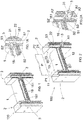
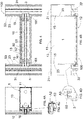
- the assembly (100) comprises a crosspiece (1), an upright (2) and a connection element (3) disposed between the crosspiece (1) and the upright (2).
- the crosspiece (1) has a rectangular shape and comprises a back side (11) suitable for facing a wall of a building, a front side (12) suitable for facing the exterior of the building, an upper side (13) and a lower side (14).
- the crosspiece (1) has two rectilinear lateral edges (15) at right angle with the front side and the back side.
- the crosspiece (1) comprises a shelf (16) that projects from the front side (12) of the crosspiece.
- the shelf (16) has two lateral edges (161) that are aligned with the lateral edges (15) of the crosspiece (1).
- the shelf (16) of the upright (1) is suitable for supporting a cover panel (P) for covering a facade of a building.
- the cover panel (P) can be internally empty to ensure a good thermal insulation.
- the panel (P) has a lower edge (P1) and a lateral edge (P2).
- the lower edge (P1) of the panel is disposed in contact with the shelf (16).
- the upright (2) has a back side (21) suitable for facing a wall of the building, a front side (22) suitable for facing the exterior of the building, and two lateral sides (23).
- the crosspiece (1) is disposed between the lateral sides (3) of two uprights.
- the assembly (100) may comprise closing elements (not shown in the drawings) to close empty spaces between the panel (P), the crosspiece (1) and the upright (2).
- connection element (3) is disposed between the lateral edge (161) of the shelf (16) and the front side (22) of the upright (2).
- connection element (3) is a seal made of a soft elastomeric material that is tightly engaged in the crosspiece and in the upright; preventing water from infiltrating between the crosspiece and the upright.
- the connection element is made in one piece.
- connection element (3) is suitably configured to act as conveyor element in such a way that the water that is deposited on the shelf (16) is drained laterally towards the upright (2), without encountering any obstacle and reaching the front side (22) of the upright in order to be drained along the front side of the upright. In this way, the water is prevented from draining frontally from the shelf and from penetrating in an empty space between the lateral edge (166) of the shelf and the lateral side (23) of the upright.
- the crosspiece (1) comprises fixing seats (S2, S2') for fixing the connection element (3).
- the upright (2) comprises a fixing seat (S3) for fixing the connection element (3).
- connection element (3) comprises:
- the fixing seats (S2, S2') of the crosspiece comprise:
- the grooves (S2, S2') have a narrowed opening, in such a way to define undercut parts.
- the first fixing means (A2, A2') of the connection element (3) comprise a first tooth (A2) and a second tooth (A2').
- the first tooth and the second tooth (A2, A2') are respectively inserted in the first and in the second groove (S2, S2') of the crosspiece.
- each tooth (A2, A2') of the first fixing means comprises a hook (33) that protrudes laterally outwards in order to be inserted through the narrowed opening of the grooves (S2, S2') of the crosspiece and be fixed in the undercut parts of the grooves of the crosspiece, in such a way to firmly fix the connection element to the crosspiece.
- the shelf (16) comprises a guide seat (S1) composed of a notch provided on the shelf (16) of the crosspiece (1).
- connection element (3) comprises guide means (A1) that are engaged in the guide seat (S1) of the shelf.
- the notch (S1) of the guide seat of the shelf has a U-shaped section with concavity directed towards the exterior of the building.
- the guide means (A1) of the connection element comprise a central wing (34) disposed between the two teeth (A1, A2).
- the central wing (34) is inserted in the notch of the guide means (S1) of the shelf and acts as guide for the correct alignment of the connection element. It must be noted that, when the central wing (34) of the connection element is inserted in the guide seat (S1) of the shelf, the tooth (A2) in upper position is separated from the upper surface of the shelf, in order to not interfere with the water flow from the shelf (16) towards the connection element (3)
- connection element (3) comprises a central portion (31) connected to the central wing (34).
- an upper surface of the central portion (31) of the connection element is disposed at the same height as an upper surface of the shelf (16), in correspondence of the lateral edge (161) of the shelf (16), in such a way that the water on the shelf can flow freely from the shelf to the central portion (31) of the connection element, without encountering any obstacle.
- a step (35) is provided between the central wing (34) and the central portion (31) of the connection element, and is stopped against the lateral edge (161) of the shelf.
- the thickness of the step (35) is such that an upper surface of the central portion (31) of the connection element is disposed at the same level as an upper surface of the shelf (16), in correspondence of the lateral edge (161) of the shelf (16).
- the central portion (31) of the connection element (3) has an upper surface with a first section (36) that is parallel to the central wing (34) and a second section (37) that is inclined relative to the first section (36).
- first section (36) of the central portion of the connection element is coplanar to the upper surface of the shelf, and the second section (37) of the central portion of the connection element is inclined downwards to favor the water drainage towards the front side (22) of the upright (2).
- the central wing (34) of the connection element that is disposed in the notch of the guide means (S1) of the shelf permits the stabilization of the connection element (3) in position, in such a way that the first section (36) of the central portion of the connection element is perfectly coplanar to the upper surface of the shelf (16).
- the fixing seat (S3) of the upright is a longitudinal notch on the front side (22) of the upright, near the lateral side (23) of the upright.
- the second fixing means (A3) of the connection element (3) comprise at least three retention teeth (A3) that are fastened inside the longitudinal notch of the fixing seat (S3) of the upright.
- the retention teeth (A3) are aligned in such a way to have a central retention tooth and two lateral retention teeth.
- each retention tooth (A3) comprises a hooked end (B).
- the hooked end of the central retention tooth is directed in the opposite direction relative to the hooked ends of the lateral retention teeth. More precisely, the hooked end of the central retention tooth is directed towards the upright (1), whereas the hooked ends of the lateral retention teeth are directed in the opposite direction.
Landscapes
- Engineering & Computer Science (AREA)
- Architecture (AREA)
- Physics & Mathematics (AREA)
- Electromagnetism (AREA)
- Civil Engineering (AREA)
- Structural Engineering (AREA)
- Hybrid Cells (AREA)
- Finishing Walls (AREA)
Applications Claiming Priority (1)
| Application Number | Priority Date | Filing Date | Title |
|---|---|---|---|
| IT102019000000703A IT201900000703A1 (it) | 2019-01-16 | 2019-01-16 | Guarnizione e gruppo montante-traversa comprendente detta guarnizione. |
Publications (1)
| Publication Number | Publication Date |
|---|---|
| EP3683374A1 true EP3683374A1 (fr) | 2020-07-22 |
Family
ID=66218320
Family Applications (1)
| Application Number | Title | Priority Date | Filing Date |
|---|---|---|---|
| EP20150454.5A Withdrawn EP3683374A1 (fr) | 2019-01-16 | 2020-01-07 | Assemblage de montant et traverse |
Country Status (2)
| Country | Link |
|---|---|
| EP (1) | EP3683374A1 (fr) |
| IT (1) | IT201900000703A1 (fr) |
Cited By (1)
| Publication number | Priority date | Publication date | Assignee | Title |
|---|---|---|---|---|
| DE102022130502B3 (de) | 2022-11-17 | 2024-03-28 | Hydro Extruded Solutions As | Verbinderbaugruppe und Pfosten-Riegel-Konstruktion |
Citations (3)
| Publication number | Priority date | Publication date | Assignee | Title |
|---|---|---|---|---|
| FR2694953A1 (fr) * | 1992-08-18 | 1994-02-25 | Aluvar Sa | Pièce de raccordement pour monter une traverse sur un raidisseur de mur-rideau. |
| DE9305394U1 (de) * | 1993-04-08 | 1994-08-11 | Kawneer Aluminium GmbH, 4050 Mönchengladbach | Rahmenkonstruktion, insbesondere für Fassadenverkleidungen |
| EP2762669A2 (fr) | 2013-01-30 | 2014-08-06 | Alcoa Aluminium Deutschland, Inc. | Structure de profilés avec joint d'étanchéité |
Family Cites Families (1)
| Publication number | Priority date | Publication date | Assignee | Title |
|---|---|---|---|---|
| ATE351949T1 (de) * | 2002-11-08 | 2007-02-15 | Alprogetti Srl | System für die frontverbindung von pfosten und riegeln |
-
2019
- 2019-01-16 IT IT102019000000703A patent/IT201900000703A1/it unknown
-
2020
- 2020-01-07 EP EP20150454.5A patent/EP3683374A1/fr not_active Withdrawn
Patent Citations (3)
| Publication number | Priority date | Publication date | Assignee | Title |
|---|---|---|---|---|
| FR2694953A1 (fr) * | 1992-08-18 | 1994-02-25 | Aluvar Sa | Pièce de raccordement pour monter une traverse sur un raidisseur de mur-rideau. |
| DE9305394U1 (de) * | 1993-04-08 | 1994-08-11 | Kawneer Aluminium GmbH, 4050 Mönchengladbach | Rahmenkonstruktion, insbesondere für Fassadenverkleidungen |
| EP2762669A2 (fr) | 2013-01-30 | 2014-08-06 | Alcoa Aluminium Deutschland, Inc. | Structure de profilés avec joint d'étanchéité |
Cited By (1)
| Publication number | Priority date | Publication date | Assignee | Title |
|---|---|---|---|---|
| DE102022130502B3 (de) | 2022-11-17 | 2024-03-28 | Hydro Extruded Solutions As | Verbinderbaugruppe und Pfosten-Riegel-Konstruktion |
Also Published As
| Publication number | Publication date |
|---|---|
| IT201900000703A1 (it) | 2020-07-16 |
Similar Documents
| Publication | Publication Date | Title |
|---|---|---|
| KR101446899B1 (ko) | ㄷ자 형상의 롤러지지대를 구비한 평레일 창호장치 | |
| CA2684307C (fr) | Plinthe reversible pour couvrir le bord d'un revetement de sol | |
| HU224932B1 (en) | Skirting board with finishing elements | |
| US20170260752A1 (en) | System and method for mounting wall panels secured to a wall | |
| EP3464748B1 (fr) | Mur rideau et kit de montage pour un tel mur rideau | |
| WO2006094394A1 (fr) | Systeme de mur-rideau | |
| US4271652A (en) | Facing | |
| EP3464746A1 (fr) | Mur rideau | |
| US9834941B1 (en) | Thermal break system for wall panels secured to an existing wall | |
| JP6980448B2 (ja) | 軒先構造 | |
| EP3447211B1 (fr) | Élément profilé pour terrasses et balcons | |
| CN100370090C (zh) | 装配幕墙的方法以及采用该方法装配的幕墙 | |
| KR101717570B1 (ko) | 창틀 프레임 구조체 | |
| EP3683374A1 (fr) | Assemblage de montant et traverse | |
| KR100900479B1 (ko) | 물받이가 구비된 조립식 창틀용 프레임구조 | |
| KR101894735B1 (ko) | 커튼월 구조 | |
| US20230022415A1 (en) | Lintel cover | |
| US5704410A (en) | Curtain rail and flower rack | |
| FI105712B (fi) | Julkisivun viimeistelyjärjestelmä | |
| KR101953203B1 (ko) | 범용성을 구비하는 커튼월 이중 외피 시스템창호 및 이의 시공방법 | |
| US20160376833A1 (en) | Louver Assembly | |
| KR102018426B1 (ko) | 재단 및 조립이 용이한 입면 분할 창호 | |
| EP0548773A1 (fr) | Façade continue autoportante pour bâtiments avec des éléments indépendants | |
| EP2322737A2 (fr) | Ensemble de lattes de finition pour ouverture de construction | |
| JP7599298B2 (ja) | 縦枠及びカーテンウォール |
Legal Events
| Date | Code | Title | Description |
|---|---|---|---|
| PUAI | Public reference made under article 153(3) epc to a published international application that has entered the european phase |
Free format text: ORIGINAL CODE: 0009012 |
|
| STAA | Information on the status of an ep patent application or granted ep patent |
Free format text: STATUS: THE APPLICATION HAS BEEN PUBLISHED |
|
| AK | Designated contracting states |
Kind code of ref document: A1 Designated state(s): AL AT BE BG CH CY CZ DE DK EE ES FI FR GB GR HR HU IE IS IT LI LT LU LV MC MK MT NL NO PL PT RO RS SE SI SK SM TR |
|
| AX | Request for extension of the european patent |
Extension state: BA ME |
|
| STAA | Information on the status of an ep patent application or granted ep patent |
Free format text: STATUS: THE APPLICATION IS DEEMED TO BE WITHDRAWN |
|
| 18D | Application deemed to be withdrawn |
Effective date: 20210123 |