EP3683377B1 - Isolierrahmen und installationsverfahren dafür - Google Patents
Isolierrahmen und installationsverfahren dafür Download PDFInfo
- Publication number
- EP3683377B1 EP3683377B1 EP20152316.4A EP20152316A EP3683377B1 EP 3683377 B1 EP3683377 B1 EP 3683377B1 EP 20152316 A EP20152316 A EP 20152316A EP 3683377 B1 EP3683377 B1 EP 3683377B1
- Authority
- EP
- European Patent Office
- Prior art keywords
- insulating frame
- roof
- section
- attachment
- insulating
- Prior art date
- Legal status (The legal status is an assumption and is not a legal conclusion. Google has not performed a legal analysis and makes no representation as to the accuracy of the status listed.)
- Active
Links
Images



Classifications
-
- E—FIXED CONSTRUCTIONS
- E04—BUILDING
- E04D—ROOF COVERINGS; SKY-LIGHTS; GUTTERS; ROOF-WORKING TOOLS
- E04D13/00—Special arrangements or devices in connection with roof coverings; Protection against birds; Roof drainage ; Sky-lights
- E04D13/03—Sky-lights; Domes; Ventilating sky-lights
- E04D13/0305—Supports or connecting means for sky-lights of flat or domed shape
- E04D13/031—Supports or connecting means for sky-lights of flat or domed shape characterised by a frame for connection to an inclined roof
-
- E—FIXED CONSTRUCTIONS
- E04—BUILDING
- E04D—ROOF COVERINGS; SKY-LIGHTS; GUTTERS; ROOF-WORKING TOOLS
- E04D13/00—Special arrangements or devices in connection with roof coverings; Protection against birds; Roof drainage ; Sky-lights
- E04D13/03—Sky-lights; Domes; Ventilating sky-lights
- E04D13/032—Supports or connecting means for sky-lights of vaulted shape
Definitions
- the present invention relates to an insulating frame for a roof window mounted in an inclined roof structure of a building, comprising top, bottom and side frame members, each including an insulating member and a support member, and a plurality of connector brackets, said insulating frame defining an inner opening adapted to surround a frame of the roof window and said insulating frame having an interior side intended to face the interior of the building and an exterior side intended to face the exterior and each frame member having an inner side facing the inner opening and an outer side facing away from the inner opening, said insulating frame further defining a base plane at the interior side of the insulating frame members which is substantially parallel with the inner opening.
- Such insulating frames have found wide use and considerably improved the insulating properties of inclined roofs with roof windows, as well as the ease with which a window may be installed in an inclined roof structure.
- EP2677092A1 flanges on the support members are used for connecting the insulating frame to the roof structure and since they extend over substantially the entire length of the insulating frame members this insulating frame can easily be connected to virtually any roof structure.
- the insulating frame is simply inserted in the pre-made opening in the roof structure and the flanges on the support member will then automatically come into abutment with portions of the roof structure, such as battens, to which they may be attached.
- an insulating frame as claimed, in particular where the insulating frame comprises a set of roof connector brackets adapted for connecting the insulating frame to the roof structure and at least one attachment section , wherein each of the roof connector brackets comprises a first connecting section and a second connecting section, where the first connecting section is connected to an attachment section, and where the second connecting section is adapted for connecting to the roof structure and extends away from the inner opening of the insulating frame in the assembled state in parallel with the base plane and beyond the outer side of the frame member to which the roof connector bracket is attached, where said attachment section(s) allow attachment of each roof connector bracket at several different positions depending on the design of the roof structure, and where one or more of the roof connector brackets are adapted for displaceable attachment to the attachment section such that the one or more connector brackets may be moved along a length direction of the attachment section after being attached.
- roof connector brackets can be attached at the positions fitting the design of the specific roof structure in which it is to be used, thus providing high versatility with a minimum material consumption.
- top, bottom and side are used to indicate the intended position of different parts in the mounted position even though these parts may be located differently during for example storage and transportation or prior to assembly of the insulating frame.
- internal and exitterior are used to indicate that something is intended to face the interior or exterior of the building in which the roof window is mounted, respectively, and the terms “inner” and “outer” that something is intended for facing towards or away from the inner opening of the insulating frame, respectively, in the mounted state.
- the roof connector brackets having a first connecting section adapted for connecting to the at least one attachment section may have the effect of improving handling and transportation as the connector brackets and the insulating frame members may be provided separately so that the insulating frame can be assembled in-situ.
- One or more of the roof connector brackets being adapted for displaceable attachment to the attachment section such that the one or more connector brackets may be moved along the length direction of the attachment section after being attached may have the effect of improving the ease of installation of the roof window as the position of the roof connector brackets may be adjusted once mounted e.g. by moving one or more roof connector brackets to a desired position e.g. a position where the roof connector bracket is located over a batten of the roof structure and may be connected thereto. This has the further effect that the risk of roof connector brackets being lost or forgotten is reduced compared to embodiments where they are to be attached by the installer.
- lactable attachment may be understood as being able to be moved along an attachment section in the length direction of an insulating frame member after being attached, without substantially damaging the connector brackets and/or attachment section and/or support member and/or insulating member and/or frame member and/or insulating frame e.g. by pushing or pulling the connector bracket.
- the roof connector brackets as such may be of different shapes, lengths, widths and/or heights.
- the first connecting sections and/or second connecting sections of the roof connector brackets may be of different shapes lengths, widths and/or heights. This may have the effect that it allows the insulating frame to be adapted to a given roof structure by using the appropriate types of roof connector brackets.
- the roof connector brackets may be made of wood, steel, stainless steel, aluminium, other metals, polymers, ceramics, glass fibre, composites and/or combinations thereof.
- the roof connector brackets may comprise a support section.
- the support section may engage with the attachment section and/or support member and/or insulating member and/or insulating frame member. This may have the effect of improving the connection between the roof connector bracket and the insulating frame member and thus improving the strength and stability of the insulating frame.
- the support section may be in the form of a plate that is pressed into engagement.
- the attachment section may be on an insulating member or a support member.
- the attachment section may be a separate element or be an integrated part of an insulating member or a support member.
- the attachment section may be made from a material different from the insulating and/or support member. This may have the effect that materials of the different components of the insulating frame may be optimised to the specific purpose such as thermal properties, strength, cost and/or ease of manufacture.
- the attachment section may comprise interconnecting means for interconnecting with roof connector brackets.
- the interconnecting means may be in the form of channels or grooves adapted for engaging with first connecting sections of the roof connector brackets.
- the interconnecting means may be in the form of rivets, screws, nails, spikes, or the like.
- the interconnecting means may for example engage by snap-locking, barbed sections, and/or press fitting.
- a barbed section can include lugs, pins or other protrusions looking like semi-pierced fingernail detent formed into the connector bracket or guide member e.g. by punching or stamping.
- the barbed section may facilitate snap-locking.
- space-locking may be understood as the connector bracket mechanically fastening itself to the attachment section once it is brought into the correct position.
- the length of the attachment section may be of substantially the same length as the insulating frame member and/or insulating member and/or support member.
- the length of the attachment section and/or the support member may be less than 3/4, 1/2, 1/3, 1/4, or 1/5 of the length of an insulating frame member.
- the insulating frame member may also comprise several attachment sections.
- the attachment section being of substantially the same length as the insulating frame member may improve the ease of installation of the insulating frame as the connector bracket may then be placed at virtually any desired location on the attachment section e.g. at a location where the connector bracket will be proximal to a batten of the roof structure such that it may be connected thereto.
- the attachment section may be a separate part of the insulating frame. This may have the effect that the attachment section may be selectively arranged at a desired location, such as near the battens of the roof structure. This may also have the effect that the insulating frame may be tailored to a certain roof structure by varying the number and location of the at least one attachment section.
- the attachment section may be a different material to the rest of the insulating frame member.
- the attachment section may be a high density foam where the insulating member is a low density foam.
- the attachment section is located at an exterior side of an insulating frame member. This may have the advantage that it improves the ease with which roof connector brackets may be attached to the attachment section, thus improving the ease of installation of the insulating frame.
- the attachment section is made from a material chosen from the following group: wood, metal, polymer, high rigidity polymer foam such as EPS (expanded polystyrene) or combinations thereof, where the material may comprise perforations.
- EPS expanded polystyrene
- the attachment section may be made from the same material as the support member and vice versa.
- the support member is made from a rigid insulating material, such as a non-elastic foamed polymer.
- the attachment section may then be a part of the support member.
- the attachment sections may be adapted to interconnect with one or more other attachment sections, for example via a mortise joint or the like. In this way, it is for example possible to establish a continuous series of attachment sections extending along the entire insulating frame, and it is of course also possible to provide one continuous attachment section extending all the way around the insulating frame.
- the first connecting section of the roof connector brackets is adapted for detachable attachment.
- attachment may be understood as being able to be removed by non-destructive mechanical action where neither the insulating frame, attachment section or connector bracket is substantially damaged and the connector bracket is able to be reattached to the attachment section. For example, by pulling the connector bracket off.
- the roof connector brackets being detachable may have the effect of improving the ease of installation of the insulating frame as a wrongly placed roof connector bracket may be detached and reattached at the required location. It may also improve the ease of transportation of the insulating frame as the roof connector brackets may be transported, packaged and/or shipped pre-attached to the insulating frame in a position optimal for packaging and transportation and then moved during installation. It may also improve maintenance, should it be required, as a potentially damaged roof connector bracket may simply be removed and replaced. It may also provide a greater flexibility of installation as the insulating frame may be adapted to different installation scenarios by varying the number and/or types of roof connector brackets used in-situ.
- the first connecting section extends over half or less than half the length of an insulating frame member.
- the first connecting section of the roof connector brackets are adapted for attachment via snap-locking.
- the first connecting sections may alternatively be adapted for being attached to the attachment section by screws, bolts, spikes or the like.
- the first connection section may comprise a tab for releasing the roof connector bracket from the attachment section.
- the first connecting section may comprise interconnecting means in the form of a barbed section.
- the barbed section can include lugs, pins or other protrusions looking like semi-pierced fingernail detent formed into the connector bracket or guide member e.g. by punching or stamping.
- the barbed section may facilitate snap-locking.
- the second connecting section of the roof connector brackets comprises means for attachment to a roof structure such as holes for screws, spikes, nails and the like.
- the second connecting section may be in the form of one or more flanges extending over at least a part of the length of the roof connector bracket and projecting from the frame away from the opening in the mounted state.
- the flange may comprise a series of holes and/or recesses and/or openings adapted for allowing a screw, nail, rivet or spike to pass through for securing the connector bracket to a roof structure.
- roof connector brackets at one side of the insulating frame may be connected first to the corresponding side insulating frame member while roof connector brackets at the opposite side of the insulating frame are connected first to the roof structure, so that the insulating frame can be swung into place in the opening in the roof structure.
- An insulating frame 100 will now be described in reference to Fig. 1 .
- An insulating frame 100 like this is typically installed in a suitable opening in a roof structure (not shown).
- the insulating frame provides an insulating barrier at the interface between a roof window (not shown) and the roof structure, and facilitates easier mounting of the roof window by providing a predefined space adapted for the window.
- the frame 100 can be delivered as a complete kit for assembly including a plurality of insulating members 112, a plurality of support members 114 and a plurality of roof connector brackets 200, providing a convenient solution for the installer.
- the insulating frame 100 has an exterior side adapted to face away from the interior of the building (facing upwards in Fig.
- the insulating frame 100 may also be delivered in a partly or completely assembled state.
- the insulating frame 100 comprises top 110c, bottom 110d and side insulating frame members 110a and 110b, which refer to their location when mounted, support members and a plurality of connector brackets 200 as will be discussed in more detail below.
- the insulating frame members 110a-110d define an inner opening 3.
- the insulating frame members comprise a ledge 120 projecting towards the inner opening 3, which is intended to project underneath a frame of a roof window, which the insulating frame 100 is intended to receive.
- the outer side of the insulating frame 100 is intended to face the opening in the roof structure.
- the insulating members 112 which make up the majority of the volume of the insulating frame 100, are made from a material of a dimensionally stable nature having good thermal insulating properties.
- the insulating members of the side insulating frame members 110a, 110b further comprise a softer material on the outer side, which is compressible so as to allow it to yield and adapt to the shape of the opening in the roof structure. Further details of this are described in the applicants granted patent EP2677092B1 .
- the insulating members of the side insulating frame members 110a, 110b are made from two types of polymer foam. It is, however, also possible to make them from a single material, and/or for the insulating members of the top and bottom insulating frame members 110c, 110d to be made from different materials or combinations of materials.
- roof connector brackets 200a and 200b which may be collectively referred with reference number 200
- the connector brackets 200 are attached to the attachment sections 500 of the insulating frame members 110d and 110a via their respective first connection sections 220 best seen in Fig. 4 .
- the insulating frame 100 need not be attached to battens (not shown) or other parts of the roof structure, but may simply rest on top of these as the subsequent fastening of the roof window will also secure the insulating frame 100.
- holes 213, which allow a clamp, nail, spike or screw to pass, are provided in the second connecting sections 210.
- the features here described in relation to the bottom insulating frame member 110d and one of the side insulating frame member 110a also apply to the other side insulating frame member 110b and the top insulating frame member 110d, which are substantially the same.
- the first type of roof connector bracket 200a used at the corners is an angular L shaped bracket having two legs, where each leg comprises a first connecting section 220, a second connecting section 210 and a support section 250 best seen in Fig. 4 .
- the angular L shape allows the roof connector bracket 200a to be attached to two insulating frame members 110 such as shown in Fig. 1 .
- This roof connector bracket 200a also acts as a corner or frame connector bracket interconnecting the two insulating frame members with the additional advantages of the second connecting section 210 of a roof connector bracket 200.
- the first connecting section 220 of each leg of the roof connector bracket 200a comprises interconnecting means in the form of a barbed section, as shown in Fig. 4 , which engage with the interconnecting means 130 (see Fig. 3 ) of attachment sections 500.
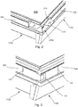
- the roof connecter bracket When the roof connecter bracket is interconnected with the two adjacent insulating frame members 110 it envelopes a corner of the insulating frame 100 as shown in Fig. 2 .
- the attachment sections 500 are adapted to join together at the corners of the insulating frame 100 by a mortise joint 140.
- the attachment sections in this embodiment are made from EPS foam, but other dimensionally stable materials might also be employed.
- the second type of roof connector bracket 200b also attaches directly to the attachment section 500 and may be attached at any desired location along the attachment section 500.
- the second connecting section 210 of this roof connector bracket 200b may also comprise holes, openings and/or recesses allowing screws, spikes, nails and the like to pass through to secure the insulating frame 100 to a roof structure.
- Fig. 5 shows a roof connector bracket 200b of the second type attached to an attachment section 500 via the brackets 200b first connecting section 220.
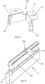
- the first connecting section 220 of this roof connector bracket 200b is better seen in the enlarged close-up view of the bracket 200b in Fig. 6 .
- the first connecting section 220 of the bracket 200b comprises two barbed sections which engage with corresponding grooves in the attachment section 500 (best seen in Fig. 5 ) and snap-lock thereto.
- bracket in Figs 5-6 is shorter than those shown in Fig. 1 it is to be understood that it serves the same purpose and has substantially the same features as described with reference to Fig. 1 , and vice versa.
- the insulating frame members 110 comprise an attachment section 600 that is a separate part to the insulating member 112 and which comprises one or more grooves or tracks 510 located at an exterior side of the insulating frame.
- the attachment section 600 is arranged within a channel in the insulating frame member.
- the one or more grooves or tracks 510 of the attachment section 600 enables a roof connector bracket 200 adapted for displaceable attachment to be displaceably attached to an insulating frame member 110.
- connector brackets 200 may be moved once it has been connected to the attachment section 600 and so allows for in-situ adjustment of the connector bracket 200 location, for example, to move it to a better suited mounting position near a batten of the roof structure. It provides the further advantage that the connector brackets 200 may be pre-connected to the insulating frame 100 e.g. for packaging, shipping and/or optimisation of installation process efficiency, and then still be adapted in-situ to a specific roof structure on-site.
- Attachment section 600 may be made from any suitable material such as for example foamed ABS, EPS, PP, GF, stainless steel, metals, polymers and/or combinations thereof.
- the attachment section 500 comprises a number of channels for connecting and supporting roof connector brackets 200 as seen in Fig. 9 .
- the attachment section 500 is made of a high rigidity foam, which is substantially non-elastic, and the insulating member 112 is made of a lower rigidity foam.
- the high rigidity foam provides the necessary strength and support to ensure adequate stability of the insulating frame as well as a secure connection of the connector bracket 200, while at the same time having insulating properties.
- the connector brackets 200 may be connected to the attachment section 500 by sliding them into the channels of the attachment section 500.
- the attachment section 500 is made of an EPS foam. It is, however, also possible to make the attachment section 500 and/or the roof connector bracket 200 from a material, which has/have sufficient elasticity to allow the roof connector bracket to snap onto the attachment section.
- support members 114 need not be separate parts to the attachment section as shown in Fig. 8 , but may be an integral part of the attachment section 500, 600.
- the roof connector brackets 200 may be adapted for detachable attachment such that they may be attached and detached from the attachment section 500, 600, for example to adapt the insulating frame 100 to a specific roof structure. This may be achieved by the connector bracket 200 being adapted for snap-locking, for example through a barbed section engaging with a complimenting interconnecting section on an attachment section such as in Figs. 4 and 6 .
- the connector brackets 200 may be made of a material chosen from the following group: wood, steel, stainless steel, aluminium, other metals, polymers, ceramics, glass fibre, composites and combinations thereof, but are preferably made of aluminium.
Landscapes
- Engineering & Computer Science (AREA)
- Architecture (AREA)
- Civil Engineering (AREA)
- Structural Engineering (AREA)
- Roof Covering Using Slabs Or Stiff Sheets (AREA)
Claims (9)
- Isolierungsrahmen (100) für ein Dachfenster, das in einer geneigten Dachstruktur eines Gebäudes montiert ist, umfassend ein oberes, ein unteres und Seitenrahmenglieder (110c, 110d, 100a, 100b), die jeweils ein Isolierungsglied (112) und ein Stützglied (114) aufweisen, und eine Vielzahl von Verbinderhalterungen (200), wobei der Isolierungsrahmen (100) eine innere Öffnung (3) definiert, die dazu ausgeführt ist, einen Rahmen des Dachfensters zu umgeben, und wobei der Isolierungsrahmen (100) eine Innenseite, die dazu bestimmt ist, in das Innere des Gebäudes zu weisen, und eine Außenseite hat, die dazu bestimmt ist, nach außen zu weisen, und wobei jedes Rahmenglied (110a - 100d) eine Innenseite, die der inneren Öffnung (3) zugewandt ist, und eine Außenseite hat, die von der inneren Öffnung (3) abgewandt ist, wobei der Isolierungsrahmen (100) ferner eine Basisebene an der Innenseite der Isolierungsrahmenglieder (110a - 100d) definiert, die im Wesentlichen parallel zu der inneren Öffnung (3) verläuft, wobei der Isolierungsrahmen (100) einen Satz Dachverbinderhalterungen (200) umfasst, die dazu ausgeführt sind, den Isolierungsrahmen (100) mit der Dachstruktur und mindestens einem Anbringabschnitt (500, 600) zu verbinden, wobei jede der Dachverbinderhalterungen (200) einen ersten Verbindungsabschnitt (220) und einen zweiten Verbindungsabschnitt (210) umfasst, wobei der erste Verbindungsabschnitt (220) mit einem Anbringabschnitt (500, 600) verbunden ist und wobei der zweite Verbindungsabschnitt (210) dazu ausgeführt ist, mit der Dachstruktur verbunden zu werden, und sich im zusammengebauten Zustand parallel zu der Basisebene und über die Außenseite des Rahmenglieds (110a - 100d) hinaus, an dem die Dachverbinderhalterung (200) angebracht ist, von der inneren Öffnung (3) des Isolierungsrahmens (100) weg erstreckt,
wobei der/die Anbringabschnitt/e (500, 600) das Anbringen jeder Dachverbinderhalterung (200) an mehreren verschiedenen Positionen in Abhängigkeit von der Auslegung der Dachstruktur gestattet/n, dadurch gekennzeichnet, dass die eine oder die mehreren Dachverbinderhalterungen (200) für eine verschiebbare Anbringung an dem Anbringabschnitt (500, 600) ausgeführt sind, so dass die eine oder die mehreren Verbinderhalterungen (200) nach dem Anbringen entlang einer Längenrichtung des Anbringabschnitts (500, 600) bewegt werden können. - Isolierungsrahmen (100) nach dem vorhergehenden Anspruch, wobei der erste Verbindungsabschnitt (220) der Dachverbinderhalterungen (200) für das lösbare Anbringen an einem Isolierungsrahmenglied (110a - 100d) ausgeführt ist.
- Isolierungsrahmen (100) nach einem der vorhergehenden Ansprüche, wobei der Anbringabschnitt (500, 600) an einer Außenseite eines Rahmenglieds (110a - 100d) angeordnet ist.
- Isolierungsrahmen (100) nach einem der vorhergehenden Ansprüche, wobei der erste Verbindungsabschnitt (220) der Dachverbinderhalterungen (200) zum Anbringen über Rastverriegelung ausgeführt ist.
- Isolierungsrahmen (100) nach einem der vorhergehenden Ansprüche, wobei der Anbringabschnitt (500, 600) aus einem aus der folgenden Gruppe ausgewählten Material hergestellt ist: Holz, Stahl, rostfreier Stahl, Aluminium, andere Metalle, Polymere, geschäumte Polymere, Keramik, Glasfaser oder Kombinationen davon, wobei das Material Perforationen umfassen kann.
- Isolierungsrahmen (100) nach einem der vorhergehenden Ansprüche, wobei das Stützglied (114) aus einem starren Isolierungsmaterial wie einem nicht elastischen geschäumten Polymer hergestellt ist.
- Isolierungsrahmen (100) nach einem der vorhergehenden Ansprüche, wobei der zweite Verbindungsabschnitt (210) der Dachverbinderhalterungen (200) Mittel zum Anbringen an einer Dachstruktur wie Löcher für Schrauben, Bolzen, Nägel u. ä. umfasst.
- Verfahren zum Installieren eines Isolierungsrahmens (100) in einer Dachstruktur, umfassend die folgenden Schritte:- Bereitstellen eines oberen, eines unteren und von Seitengliedern (110c, 110d, 100a, 100b) des Isolierungsrahmens (100), die jeweils ein Isolierungsglied (112) und ein Stützglied (114) aufweisen, wobei der Isolierungsrahmen (100) eine innere Öffnung (3) definiert, die dazu ausgeführt ist, einen Rahmen des Dachfensters zu umgeben, und wobei der Isolierungsrahmen (100) eine Innenseite, die dazu bestimmt ist, in das Innere des Gebäudes zu weisen, und eine Außenseite hat, die dazu bestimmt ist, nach außen zu weisen, und wobei jedes Rahmenglied (110a - 100d) eine Innenseite, die der inneren Öffnung (3) zugewandt ist, und eine Außenseite hat, die von der inneren Öffnung (3) abgewandt ist, wobei der Isolierungsrahmen (100) ferner eine Basisebene an der Innenseite der Isolierungsrahmenglieder (110a - 100d) definiert, die im Wesentlichen parallel zu der inneren Öffnung (3) verläuft, wobei der Isolierungsrahmen (100) mindestens einen Anbringabschnitt (500, 600) umfasst,- Bereitstellen einer Vielzahl von Dachverbinderhalterungen (200), wobei die Dachverbinderhalterungen (200) dazu ausgeführt sind, den Isolierungsrahmen (100) mit der Dachstruktur zu verbinden, und wobei jede der Dachverbinderhalterungen (200) einen ersten Verbindungsabschnitt (220) und einen zweiten Verbindungsabschnitt (210) umfasst, wobei der erste Verbindungsabschnitt (220) zum Verbinden mit einem Anbringabschnitt (500, 600) ausgeführt ist und wobei der zweite Verbindungsabschnitt (210) dazu ausgeführt ist, mit der Dachstruktur verbunden zu werden, und sich parallel zu der Basisebene und über die Außenseite des Rahmenglieds (110a - 100d), an dem die Dachverbinderhalterung (200) im zusammengebauten Zustand angebracht ist, hinaus von der inneren Öffnung (3) des Isolierungsrahmens (100) weg erstreckt, wobei eine oder mehrere der Dachverbinderhalterungen (200) für eine verschiebbare Anbringung an dem Anbringabschnitt (500, 600) ausgeführt sind, so dass die eine oder die mehreren Verbinderhalterungen (200) nach dem Anbringen entlang einer Längenrichtung des Anbringabschnitts (500, 600) bewegt werden können,- Verbinden der Dachverbinderhalterungen (200) über den ersten Verbindungsabschnitt (220) bzw. den zweiten Verbindungsabschnitt (210) mit dem/den Isolierungsrahmenglied/ern (110a - 100d) und/oder der Dachstruktur,- Verbinden der Dachverbinderhalterungen (200) über den ersten Verbindungsabschnitt (220) bzw. den zweiten Verbindungsabschnitt (210) mit dem jeweils anderen des Isolierungsrahmens (100) und der Dachstruktur.
- Verfahren zum Installieren eines Isolierungsrahmens (100) in einer Dachstruktur nach Anspruch 8, wobei- die Dachverbinderhalterungen (200) über den ersten Verbindungsabschnitt (220) mit einem Anbringabschnitt (500, 600) verbunden werden und- der Isolierungsrahmen (100) danach über den zweiten Verbindungsabschnitt (210) der Dachverbinderhalterungen (200) mit der Dachstruktur verbunden wird.
Priority Applications (1)
| Application Number | Priority Date | Filing Date | Title |
|---|---|---|---|
| PL20152316T PL3683377T3 (pl) | 2019-01-18 | 2020-01-16 | Rama izolacyjna i sposób montowania takiej ramy |
Applications Claiming Priority (1)
| Application Number | Priority Date | Filing Date | Title |
|---|---|---|---|
| DKPA201970038A DK201970038A1 (en) | 2019-01-18 | 2019-01-18 | Insulating frame and method for installing the same |
Publications (2)
| Publication Number | Publication Date |
|---|---|
| EP3683377A1 EP3683377A1 (de) | 2020-07-22 |
| EP3683377B1 true EP3683377B1 (de) | 2021-10-27 |
Family
ID=69177006
Family Applications (1)
| Application Number | Title | Priority Date | Filing Date |
|---|---|---|---|
| EP20152316.4A Active EP3683377B1 (de) | 2019-01-18 | 2020-01-16 | Isolierrahmen und installationsverfahren dafür |
Country Status (3)
| Country | Link |
|---|---|
| EP (1) | EP3683377B1 (de) |
| DK (1) | DK201970038A1 (de) |
| PL (1) | PL3683377T3 (de) |
Cited By (2)
| Publication number | Priority date | Publication date | Assignee | Title |
|---|---|---|---|---|
| WO2025077986A3 (en) * | 2023-10-11 | 2025-05-22 | Vkr Holding A/S | A support structure for use in mounting a roof window in a roof structure of a building, a support frame, and a method for mounting a roof window |
| EP4678842A1 (de) * | 2024-07-09 | 2026-01-14 | FIXOTHERM Fensterbank - Dichtsysteme GmbH | Vorrichtung zum einbau eines dachflächenfensters |
Family Cites Families (4)
| Publication number | Priority date | Publication date | Assignee | Title |
|---|---|---|---|---|
| DK199900873A (da) * | 1999-06-18 | 2001-04-02 | Vkr Holding As | Isoleringsramme for et ovenlysvindue |
| US6804918B2 (en) * | 2001-01-19 | 2004-10-19 | Vkr Holding A/S | Roof window assembly comprising a window component and an external screening accessory |
| EP2472027B1 (de) * | 2010-12-29 | 2017-03-15 | VKR Holding A/S | Verfahren zur Befestigung einer Abdeckung auf einem Dachfenster |
| DK177645B1 (en) | 2012-06-19 | 2014-01-27 | Vkr Holding As | An insulating frame for a roof window and a method of mounting a roof window |
-
2019
- 2019-01-18 DK DKPA201970038A patent/DK201970038A1/en not_active Application Discontinuation
-
2020
- 2020-01-16 PL PL20152316T patent/PL3683377T3/pl unknown
- 2020-01-16 EP EP20152316.4A patent/EP3683377B1/de active Active
Cited By (2)
| Publication number | Priority date | Publication date | Assignee | Title |
|---|---|---|---|---|
| WO2025077986A3 (en) * | 2023-10-11 | 2025-05-22 | Vkr Holding A/S | A support structure for use in mounting a roof window in a roof structure of a building, a support frame, and a method for mounting a roof window |
| EP4678842A1 (de) * | 2024-07-09 | 2026-01-14 | FIXOTHERM Fensterbank - Dichtsysteme GmbH | Vorrichtung zum einbau eines dachflächenfensters |
Also Published As
| Publication number | Publication date |
|---|---|
| PL3683377T3 (pl) | 2022-02-21 |
| EP3683377A1 (de) | 2020-07-22 |
| DK201970038A1 (en) | 2020-08-21 |
Similar Documents
| Publication | Publication Date | Title |
|---|---|---|
| US10027273B2 (en) | Plunger and puck mounting system for photovoltaic panels | |
| EP1985771A1 (de) | Wandrahmensystem | |
| CN102483081A (zh) | 用于将装配轨固定在螺纹杆上的装置 | |
| US5653076A (en) | Method and system for assembling a wall | |
| EP3683377B1 (de) | Isolierrahmen und installationsverfahren dafür | |
| HUT77496A (hu) | Építőelem és eljárás az építőelem felszerelésére | |
| AU2023201975B2 (en) | Roof Clip | |
| JPS61501579A (ja) | 支持組立体 | |
| KR102369808B1 (ko) | 패널의 장착 시스템 및 이 장착 시스템의 클립 | |
| EP3243976B1 (de) | Plattenspleissverbinder für lineare deckenplatten | |
| EP2204524A2 (de) | Ein Fenster oder Tür mit einer Rahmenkonstruktion mit einer Nut für ein Innenfutter | |
| JP4472545B2 (ja) | タイル取付け構造 | |
| US20140090326A1 (en) | Aesthetic wall facade systems, devices, and methods | |
| EP3683376B1 (de) | Isolierrahmen und verfahren zur herstellung eines isolierrahmens | |
| EP3792438B1 (de) | Fensterverkleidungsanordnung mit verbesserten beschlägen und verfahren zum installieren einer solchen verkleidungsanordnung an einem fenster | |
| EP4700200A1 (de) | Einrastelement für beliebige fensterinstallation an das universal-thermoprofil und verfahren zu dessen verwendung | |
| DK176245B1 (da) | Beslagsystem til montering af vindue | |
| EP4023834B1 (de) | Dachfenstersystem mit einer montageanordnung und verfahren zur installation solch eines dachfenstersystems | |
| KR20150106785A (ko) | 엘리베이터용 의장 패널 및 그의 고정 방법 | |
| EP3988735B1 (de) | Schiene zur befestigung eines hängedeckensystems an einer betondecke | |
| EP2738319B1 (de) | Klammer zur Befestigung von Metallblechen an Balken von Überdachungsflächen, Dächern oder ähnlichem | |
| AU2017201077B2 (en) | Building Panel Support | |
| FI12295U1 (fi) | Listajärjestelmä | |
| WO2008094011A1 (en) | Ceiling hanger | |
| EP4599136A1 (de) | Verfahren zur montage eines dachfensters, kit mit einem dachfenster und mindestens zwei dachelementen, dachelement, dachfenster und dachstruktur mit darin montiertem dachfenster |
Legal Events
| Date | Code | Title | Description |
|---|---|---|---|
| PUAI | Public reference made under article 153(3) epc to a published international application that has entered the european phase |
Free format text: ORIGINAL CODE: 0009012 |
|
| STAA | Information on the status of an ep patent application or granted ep patent |
Free format text: STATUS: THE APPLICATION HAS BEEN PUBLISHED |
|
| AK | Designated contracting states |
Kind code of ref document: A1 Designated state(s): AL AT BE BG CH CY CZ DE DK EE ES FI FR GB GR HR HU IE IS IT LI LT LU LV MC MK MT NL NO PL PT RO RS SE SI SK SM TR |
|
| AX | Request for extension of the european patent |
Extension state: BA ME |
|
| STAA | Information on the status of an ep patent application or granted ep patent |
Free format text: STATUS: REQUEST FOR EXAMINATION WAS MADE |
|
| 17P | Request for examination filed |
Effective date: 20210112 |
|
| RBV | Designated contracting states (corrected) |
Designated state(s): AL AT BE BG CH CY CZ DE DK EE ES FI FR GB GR HR HU IE IS IT LI LT LU LV MC MK MT NL NO PL PT RO RS SE SI SK SM TR |
|
| GRAP | Despatch of communication of intention to grant a patent |
Free format text: ORIGINAL CODE: EPIDOSNIGR1 |
|
| STAA | Information on the status of an ep patent application or granted ep patent |
Free format text: STATUS: GRANT OF PATENT IS INTENDED |
|
| INTG | Intention to grant announced |
Effective date: 20210520 |
|
| GRAS | Grant fee paid |
Free format text: ORIGINAL CODE: EPIDOSNIGR3 |
|
| GRAA | (expected) grant |
Free format text: ORIGINAL CODE: 0009210 |
|
| STAA | Information on the status of an ep patent application or granted ep patent |
Free format text: STATUS: THE PATENT HAS BEEN GRANTED |
|
| AK | Designated contracting states |
Kind code of ref document: B1 Designated state(s): AL AT BE BG CH CY CZ DE DK EE ES FI FR GB GR HR HU IE IS IT LI LT LU LV MC MK MT NL NO PL PT RO RS SE SI SK SM TR |
|
| REG | Reference to a national code |
Ref country code: GB Ref legal event code: FG4D |
|
| REG | Reference to a national code |
Ref country code: CH Ref legal event code: EP |
|
| REG | Reference to a national code |
Ref country code: AT Ref legal event code: REF Ref document number: 1441923 Country of ref document: AT Kind code of ref document: T Effective date: 20211115 |
|
| REG | Reference to a national code |
Ref country code: DE Ref legal event code: R096 Ref document number: 602020000802 Country of ref document: DE |
|
| REG | Reference to a national code |
Ref country code: IE Ref legal event code: FG4D |
|
| REG | Reference to a national code |
Ref country code: LT Ref legal event code: MG9D |
|
| REG | Reference to a national code |
Ref country code: NL Ref legal event code: MP Effective date: 20211027 |
|
| REG | Reference to a national code |
Ref country code: AT Ref legal event code: MK05 Ref document number: 1441923 Country of ref document: AT Kind code of ref document: T Effective date: 20211027 |
|
| PG25 | Lapsed in a contracting state [announced via postgrant information from national office to epo] |
Ref country code: RS Free format text: LAPSE BECAUSE OF FAILURE TO SUBMIT A TRANSLATION OF THE DESCRIPTION OR TO PAY THE FEE WITHIN THE PRESCRIBED TIME-LIMIT Effective date: 20211027 Ref country code: LT Free format text: LAPSE BECAUSE OF FAILURE TO SUBMIT A TRANSLATION OF THE DESCRIPTION OR TO PAY THE FEE WITHIN THE PRESCRIBED TIME-LIMIT Effective date: 20211027 Ref country code: FI Free format text: LAPSE BECAUSE OF FAILURE TO SUBMIT A TRANSLATION OF THE DESCRIPTION OR TO PAY THE FEE WITHIN THE PRESCRIBED TIME-LIMIT Effective date: 20211027 Ref country code: BG Free format text: LAPSE BECAUSE OF FAILURE TO SUBMIT A TRANSLATION OF THE DESCRIPTION OR TO PAY THE FEE WITHIN THE PRESCRIBED TIME-LIMIT Effective date: 20220127 Ref country code: AT Free format text: LAPSE BECAUSE OF FAILURE TO SUBMIT A TRANSLATION OF THE DESCRIPTION OR TO PAY THE FEE WITHIN THE PRESCRIBED TIME-LIMIT Effective date: 20211027 |
|
| PG25 | Lapsed in a contracting state [announced via postgrant information from national office to epo] |
Ref country code: IS Free format text: LAPSE BECAUSE OF FAILURE TO SUBMIT A TRANSLATION OF THE DESCRIPTION OR TO PAY THE FEE WITHIN THE PRESCRIBED TIME-LIMIT Effective date: 20220227 Ref country code: SE Free format text: LAPSE BECAUSE OF FAILURE TO SUBMIT A TRANSLATION OF THE DESCRIPTION OR TO PAY THE FEE WITHIN THE PRESCRIBED TIME-LIMIT Effective date: 20211027 Ref country code: PT Free format text: LAPSE BECAUSE OF FAILURE TO SUBMIT A TRANSLATION OF THE DESCRIPTION OR TO PAY THE FEE WITHIN THE PRESCRIBED TIME-LIMIT Effective date: 20220228 Ref country code: NO Free format text: LAPSE BECAUSE OF FAILURE TO SUBMIT A TRANSLATION OF THE DESCRIPTION OR TO PAY THE FEE WITHIN THE PRESCRIBED TIME-LIMIT Effective date: 20220127 Ref country code: NL Free format text: LAPSE BECAUSE OF FAILURE TO SUBMIT A TRANSLATION OF THE DESCRIPTION OR TO PAY THE FEE WITHIN THE PRESCRIBED TIME-LIMIT Effective date: 20211027 Ref country code: LV Free format text: LAPSE BECAUSE OF FAILURE TO SUBMIT A TRANSLATION OF THE DESCRIPTION OR TO PAY THE FEE WITHIN THE PRESCRIBED TIME-LIMIT Effective date: 20211027 Ref country code: HR Free format text: LAPSE BECAUSE OF FAILURE TO SUBMIT A TRANSLATION OF THE DESCRIPTION OR TO PAY THE FEE WITHIN THE PRESCRIBED TIME-LIMIT Effective date: 20211027 Ref country code: GR Free format text: LAPSE BECAUSE OF FAILURE TO SUBMIT A TRANSLATION OF THE DESCRIPTION OR TO PAY THE FEE WITHIN THE PRESCRIBED TIME-LIMIT Effective date: 20220128 Ref country code: ES Free format text: LAPSE BECAUSE OF FAILURE TO SUBMIT A TRANSLATION OF THE DESCRIPTION OR TO PAY THE FEE WITHIN THE PRESCRIBED TIME-LIMIT Effective date: 20211027 |
|
| REG | Reference to a national code |
Ref country code: DE Ref legal event code: R097 Ref document number: 602020000802 Country of ref document: DE |
|
| PG25 | Lapsed in a contracting state [announced via postgrant information from national office to epo] |
Ref country code: SM Free format text: LAPSE BECAUSE OF FAILURE TO SUBMIT A TRANSLATION OF THE DESCRIPTION OR TO PAY THE FEE WITHIN THE PRESCRIBED TIME-LIMIT Effective date: 20211027 Ref country code: SK Free format text: LAPSE BECAUSE OF FAILURE TO SUBMIT A TRANSLATION OF THE DESCRIPTION OR TO PAY THE FEE WITHIN THE PRESCRIBED TIME-LIMIT Effective date: 20211027 Ref country code: RO Free format text: LAPSE BECAUSE OF FAILURE TO SUBMIT A TRANSLATION OF THE DESCRIPTION OR TO PAY THE FEE WITHIN THE PRESCRIBED TIME-LIMIT Effective date: 20211027 Ref country code: EE Free format text: LAPSE BECAUSE OF FAILURE TO SUBMIT A TRANSLATION OF THE DESCRIPTION OR TO PAY THE FEE WITHIN THE PRESCRIBED TIME-LIMIT Effective date: 20211027 Ref country code: DK Free format text: LAPSE BECAUSE OF FAILURE TO SUBMIT A TRANSLATION OF THE DESCRIPTION OR TO PAY THE FEE WITHIN THE PRESCRIBED TIME-LIMIT Effective date: 20211027 Ref country code: CZ Free format text: LAPSE BECAUSE OF FAILURE TO SUBMIT A TRANSLATION OF THE DESCRIPTION OR TO PAY THE FEE WITHIN THE PRESCRIBED TIME-LIMIT Effective date: 20211027 |
|
| PG25 | Lapsed in a contracting state [announced via postgrant information from national office to epo] |
Ref country code: MC Free format text: LAPSE BECAUSE OF FAILURE TO SUBMIT A TRANSLATION OF THE DESCRIPTION OR TO PAY THE FEE WITHIN THE PRESCRIBED TIME-LIMIT Effective date: 20211027 |
|
| PLBE | No opposition filed within time limit |
Free format text: ORIGINAL CODE: 0009261 |
|
| STAA | Information on the status of an ep patent application or granted ep patent |
Free format text: STATUS: NO OPPOSITION FILED WITHIN TIME LIMIT |
|
| REG | Reference to a national code |
Ref country code: BE Ref legal event code: MM Effective date: 20220131 |
|
| 26N | No opposition filed |
Effective date: 20220728 |
|
| PG25 | Lapsed in a contracting state [announced via postgrant information from national office to epo] |
Ref country code: LU Free format text: LAPSE BECAUSE OF NON-PAYMENT OF DUE FEES Effective date: 20220116 Ref country code: AL Free format text: LAPSE BECAUSE OF FAILURE TO SUBMIT A TRANSLATION OF THE DESCRIPTION OR TO PAY THE FEE WITHIN THE PRESCRIBED TIME-LIMIT Effective date: 20211027 |
|
| PG25 | Lapsed in a contracting state [announced via postgrant information from national office to epo] |
Ref country code: SI Free format text: LAPSE BECAUSE OF FAILURE TO SUBMIT A TRANSLATION OF THE DESCRIPTION OR TO PAY THE FEE WITHIN THE PRESCRIBED TIME-LIMIT Effective date: 20211027 Ref country code: BE Free format text: LAPSE BECAUSE OF NON-PAYMENT OF DUE FEES Effective date: 20220131 |
|
| PG25 | Lapsed in a contracting state [announced via postgrant information from national office to epo] |
Ref country code: IE Free format text: LAPSE BECAUSE OF NON-PAYMENT OF DUE FEES Effective date: 20220116 |
|
| PG25 | Lapsed in a contracting state [announced via postgrant information from national office to epo] |
Ref country code: IT Free format text: LAPSE BECAUSE OF FAILURE TO SUBMIT A TRANSLATION OF THE DESCRIPTION OR TO PAY THE FEE WITHIN THE PRESCRIBED TIME-LIMIT Effective date: 20211027 |
|
| REG | Reference to a national code |
Ref country code: CH Ref legal event code: PL |
|
| PG25 | Lapsed in a contracting state [announced via postgrant information from national office to epo] |
Ref country code: LI Free format text: LAPSE BECAUSE OF NON-PAYMENT OF DUE FEES Effective date: 20230131 Ref country code: CH Free format text: LAPSE BECAUSE OF NON-PAYMENT OF DUE FEES Effective date: 20230131 |
|
| PG25 | Lapsed in a contracting state [announced via postgrant information from national office to epo] |
Ref country code: MK Free format text: LAPSE BECAUSE OF FAILURE TO SUBMIT A TRANSLATION OF THE DESCRIPTION OR TO PAY THE FEE WITHIN THE PRESCRIBED TIME-LIMIT Effective date: 20211027 Ref country code: CY Free format text: LAPSE BECAUSE OF FAILURE TO SUBMIT A TRANSLATION OF THE DESCRIPTION OR TO PAY THE FEE WITHIN THE PRESCRIBED TIME-LIMIT Effective date: 20211027 |
|
| PG25 | Lapsed in a contracting state [announced via postgrant information from national office to epo] |
Ref country code: HU Free format text: LAPSE BECAUSE OF FAILURE TO SUBMIT A TRANSLATION OF THE DESCRIPTION OR TO PAY THE FEE WITHIN THE PRESCRIBED TIME-LIMIT; INVALID AB INITIO Effective date: 20200116 |
|
| PG25 | Lapsed in a contracting state [announced via postgrant information from national office to epo] |
Ref country code: TR Free format text: LAPSE BECAUSE OF FAILURE TO SUBMIT A TRANSLATION OF THE DESCRIPTION OR TO PAY THE FEE WITHIN THE PRESCRIBED TIME-LIMIT Effective date: 20211027 |
|
| PG25 | Lapsed in a contracting state [announced via postgrant information from national office to epo] |
Ref country code: MT Free format text: LAPSE BECAUSE OF FAILURE TO SUBMIT A TRANSLATION OF THE DESCRIPTION OR TO PAY THE FEE WITHIN THE PRESCRIBED TIME-LIMIT Effective date: 20211027 |
|
| PGFP | Annual fee paid to national office [announced via postgrant information from national office to epo] |
Ref country code: GB Payment date: 20251204 Year of fee payment: 7 |
|
| PGFP | Annual fee paid to national office [announced via postgrant information from national office to epo] |
Ref country code: FR Payment date: 20251222 Year of fee payment: 7 |
|
| PGFP | Annual fee paid to national office [announced via postgrant information from national office to epo] |
Ref country code: PL Payment date: 20251212 Year of fee payment: 7 |
|
| PGFP | Annual fee paid to national office [announced via postgrant information from national office to epo] |
Ref country code: DE Payment date: 20251203 Year of fee payment: 7 |