EP3683483B1 - Pièce de raccordement permettant de raccorder un tuyau à un sachet de boisson - Google Patents
Pièce de raccordement permettant de raccorder un tuyau à un sachet de boisson Download PDFInfo
- Publication number
- EP3683483B1 EP3683483B1 EP19020027.9A EP19020027A EP3683483B1 EP 3683483 B1 EP3683483 B1 EP 3683483B1 EP 19020027 A EP19020027 A EP 19020027A EP 3683483 B1 EP3683483 B1 EP 3683483B1
- Authority
- EP
- European Patent Office
- Prior art keywords
- piercing
- axial
- beverage
- wall
- suction opening
- Prior art date
- Legal status (The legal status is an assumption and is not a legal conclusion. Google has not performed a legal analysis and makes no representation as to the accuracy of the status listed.)
- Active
Links
Images


Classifications
-
- F—MECHANICAL ENGINEERING; LIGHTING; HEATING; WEAPONS; BLASTING
- F16—ENGINEERING ELEMENTS AND UNITS; GENERAL MEASURES FOR PRODUCING AND MAINTAINING EFFECTIVE FUNCTIONING OF MACHINES OR INSTALLATIONS; THERMAL INSULATION IN GENERAL
- F16L—PIPES; JOINTS OR FITTINGS FOR PIPES; SUPPORTS FOR PIPES, CABLES OR PROTECTIVE TUBING; MEANS FOR THERMAL INSULATION IN GENERAL
- F16L37/00—Couplings of the quick-acting type
- F16L37/08—Couplings of the quick-acting type in which the connection between abutting or axially overlapping ends is maintained by locking members
- F16L37/084—Couplings of the quick-acting type in which the connection between abutting or axially overlapping ends is maintained by locking members combined with automatic locking
- F16L37/098—Couplings of the quick-acting type in which the connection between abutting or axially overlapping ends is maintained by locking members combined with automatic locking by means of flexible hooks
- F16L37/0985—Couplings of the quick-acting type in which the connection between abutting or axially overlapping ends is maintained by locking members combined with automatic locking by means of flexible hooks the flexible hook extending radially inwardly from an outer part and engaging a bead, recess or the like on an inner part
-
- B—PERFORMING OPERATIONS; TRANSPORTING
- B65—CONVEYING; PACKING; STORING; HANDLING THIN OR FILAMENTARY MATERIAL
- B65D—CONTAINERS FOR STORAGE OR TRANSPORT OF ARTICLES OR MATERIALS, e.g. BAGS, BARRELS, BOTTLES, BOXES, CANS, CARTONS, CRATES, DRUMS, JARS, TANKS, HOPPERS, FORWARDING CONTAINERS; ACCESSORIES, CLOSURES, OR FITTINGS THEREFOR; PACKAGING ELEMENTS; PACKAGES
- B65D2231/00—Means for facilitating the complete expelling of the contents
- B65D2231/001—Means for facilitating the complete expelling of the contents the container being a bag
- B65D2231/004—Means for facilitating the complete expelling of the contents the container being a bag comprising rods or tubes provided with radial openings, ribs or the like, e.g. dip-tubes, spiral rods
-
- B—PERFORMING OPERATIONS; TRANSPORTING
- B65—CONVEYING; PACKING; STORING; HANDLING THIN OR FILAMENTARY MATERIAL
- B65D—CONTAINERS FOR STORAGE OR TRANSPORT OF ARTICLES OR MATERIALS, e.g. BAGS, BARRELS, BOTTLES, BOXES, CANS, CARTONS, CRATES, DRUMS, JARS, TANKS, HOPPERS, FORWARDING CONTAINERS; ACCESSORIES, CLOSURES, OR FITTINGS THEREFOR; PACKAGING ELEMENTS; PACKAGES
- B65D77/00—Packages formed by enclosing articles or materials in preformed containers, e.g. boxes, cartons, sacks or bags
- B65D77/04—Articles or materials enclosed in two or more containers disposed one within another
- B65D77/06—Liquids or semi-liquids or other materials or articles enclosed in flexible containers disposed within rigid containers
- B65D77/062—Flexible containers disposed within polygonal containers formed by folding a carton blank
- B65D77/065—Spouts, pouring necks or discharging tubes fixed to or integral with the flexible container
- B65D77/067—Spouts, pouring necks or discharging tubes fixed to or integral with the flexible container combined with a valve, a tap or a piercer
-
- F—MECHANICAL ENGINEERING; LIGHTING; HEATING; WEAPONS; BLASTING
- F16—ENGINEERING ELEMENTS AND UNITS; GENERAL MEASURES FOR PRODUCING AND MAINTAINING EFFECTIVE FUNCTIONING OF MACHINES OR INSTALLATIONS; THERMAL INSULATION IN GENERAL
- F16L—PIPES; JOINTS OR FITTINGS FOR PIPES; SUPPORTS FOR PIPES, CABLES OR PROTECTIVE TUBING; MEANS FOR THERMAL INSULATION IN GENERAL
- F16L37/00—Couplings of the quick-acting type
- F16L37/08—Couplings of the quick-acting type in which the connection between abutting or axially overlapping ends is maintained by locking members
- F16L37/084—Couplings of the quick-acting type in which the connection between abutting or axially overlapping ends is maintained by locking members combined with automatic locking
- F16L37/096—Couplings of the quick-acting type in which the connection between abutting or axially overlapping ends is maintained by locking members combined with automatic locking by means of hooks hinged about an axis
Definitions
- the present invention relates to a connector for connecting a hose to a beverage bag.
- the DE 19839842 A1 discloses that in a removal device for a liquid container made of flexible material in an essentially dimensionally stable outer container surrounding it and through which the removal device penetrates, a pipe socket of the removal device is connected in a liquid-tight and gas-tight manner to the wall of the liquid container in the area of a wall opening by means of a flange collar formed onto the tubular part .
- a separate closure body which in the closed position closes the cross-section of the pipe space, is assigned to the pipe socket, which is releasably fixed to the free pipe mouth end of a connecting pipe that can be inserted axially into the pipe space and can be transferred with this from the closed position to an open position, in which the closure body attached to the pipe mouth end and at least a radial opening in the pipe wall of the pipe mouth end is arranged in the liquid container.
- the diameter of the cylindrical tube space of the tube socket is larger on the container side than on the other end, forming an annular shoulder.
- the U.S. 2004/045632 A1 discloses a bag having a flexible wall defining a closed chamber of the bag for storing a substance, such as a liquid, gaseous, pasty or powdered substance.
- a substance such as a liquid, gaseous, pasty or powdered substance.
- On the inside of the wall is attached a female element having a body through which extends a bore extending from an insertion opening for a male element, which is sealed by the wall of the bag, in the extends near the wall of the bag to an opening in the chamber of the bag.
- the bore is also closed by a closure element in such a way that a male element can pierce the part of the bag wall covering the insertion opening from the outside, so that the male element then penetrates into the bore of the female element and - during further insertion of the male element into the bore - cooperates with the closure element and releases the closure of the bore effected by the closure element.
- the U.S. R E32 354 E discloses a connector for dispensing fluids from a container having a fluid storage portion and a pouring opening, comprising an elongate member having an internal channel for transporting the fluid and having an entrance from the outside, the member being sized to fit snugly into the opening fits; and a plug disposed in the aperture and sealing the aperture by a first snap fit, the plug and member being mutually engageable by means of a second snap fit, the plug and member being mutually slidable while engaged, to allow the channel entrance to extend into the reservoir area of the container to dispense fluid, the first attachment being more difficult to undo than the second attachment to effect this, thereby ensuring mutual engagement of the member and plug stand before the plug and element are pushed into the storage area and break the seal.
- a fitting for connecting a hose to a beverage bag comprises a piercing tube with an axial piercing side, one of the axial piercing side opposite axial rear side and a casing wall, which encloses a beverage channel in a puncture direction seen from the axial rear side to the axial piercing side and connects the axial piercing side with the axial rear side, a hose connection, such as a hose nipple, connected to the axial rear side of the piercing tube and leading into the beverage channel or a connection thread for connecting the hose, and arranged between the hose connection and the axial piercing side and Abutment wall protruding radially from the casing wall, which delimits a puncture depth of the puncture tube in the beverage bag.
- the connecting piece has a suction opening leading into the beverage channel, which is arranged on the piercing tube in front of the abutment wall as seen in the piercing direction, and a spacer extending in front of the suction opening, seen in the piercing direction.
- connection piece specified is based on the consideration that the beverage bag contracts when the beverage is sucked out via the connection piece and is deformed in the process.
- the deformation is accidental and, in the case of the connection piece of the type mentioned at the outset, can result in the wall of the beverage bag lying on the suction opening, closing it and preventing further suction of beverage from the beverage bag.
- a beverage residue remains in the beverage bag, which in an emergency is disposed of unused with the beverage bag.
- the work process is stopped because the beverage bag has to be removed from the suction opening, which is time-consuming.
- connection piece specified comes into play with the idea of arranging the intake opening at a point in the connection piece in front of a spacer, which ensures that the wall cannot lie on the intake opening. This ensures that the beverage bag can always be emptied via the connecting piece.
- connection piece specified the spacer is designed as part of the jacket wall.
- the specified connection piece can be built in one piece, for example as an injection molded part, not only in a cost-effective manner, but also when the connection piece is pierced into the beverage bag, this would be prevented from simply falling apart.
- the suction opening is guided radially through the casing wall. In this way the shortest way for the beverage liquid from the beverage bag into the beverage channel is selected, with correspondingly minimized friction losses.
- a further suction opening is guided through the jacket wall radially opposite to the suction opening.
- the effective cross-sectional area for sucking the beverage liquid into the beverage channel is increased, so that the beverage liquid can be sucked in with a correspondingly higher flow and, depending on the storage, the liquid can be sucked in with a significantly higher probability.
- the suction opening and the further suction openings are congruent.
- the two suction openings can be molded into the connecting piece using a common tool.
- the intake opening is designed as a bore through the jacket wall.
- the suction opening can also be formed later in a connecting piece that has already been produced.
- a cross-sectional area of the suction opening is between 10% and 30% of a cross-sectional area of the beverage channel. In this way, the largest possible suction area is achieved without mechanically destabilizing the casing wall.
- the distance between the suction opening and the axial piercing side of the piercing tube is between 5% and 20% of a distance between the stop wall and the axial piercing side of the piercing tube.
- connecting piece in the beverage bag are pressed inwards.
- the piercing tube is open on the axial piercing side toward the beverage channel.
- the beverage channel of the connecting piece can be cleaned easily, because there are no dead points in the beverage channel in terms of flow mechanics.
- the jacket wall tapers radially in a guide area behind the axial piercing side in the piercing direction, with the suction opening being arranged behind the guiding region as seen in the piercing direction.
- the beverage bag 2 is stored a beverage that is not shown in more detail, which can be removed from the beverage bag 2 via the tube 6 and served to a guest, for example for hospitality purposes.
- the beverage is milk.
- an outlet socket 8 is placed on its wall, which opens a channel into the interior of the beverage bag 2 , which is not shown in any more detail.
- a piece of pipe 12 which can be closed with a cover 10 and which can be used to prevent beverage liquid from escaping unintentionally from the beverage bag is placed on the outlet connection piece 8 .
- the connection piece 8 has a piercing tube 14 which is pierced in a piercing direction 16 through the tube section 12 and the outlet socket 8 into the interior of the beverage bag 2 .
- a hose connection in the form of a hose nipple 20 onto which the hose 6 is attached, protrudes from the piercing tube 14 against a vertical direction 18, which extends at right angles to the piercing direction 16.
- the direction that extends at right angles to the piercing direction 16 and to the vertical direction 18 is to be referred to below as the transverse direction 22 .
- connection piece For further details of the connection piece, please refer to 2 Referred to the the fitting of 1 shows from a first perspective.
- the piercing tube 14 has at the front end an axial piercing side 26 which, seen in the piercing direction 16 , lies opposite an axial rear side 28 .
- the axial piercing side 26 and the axial rear side 28 are connected to one another via a casing wall 30 which encloses the beverage channel 24 in the region of the piercing tube 14 .
- the beverage channel 24 opens into the hose nipple 20.
- a stop wall 32 protruding radially from the casing wall 30 is arranged between the hose nipple 20 and the axial piercing side 26 of the piercing tube 14 .
- the stop wall 32 is intended to limit a puncturing depth during this puncturing process.
- a receiving chamber 34 is formed in the piece of pipe 12, in which the stop wall 32 is inserted during the aforementioned piercing process.
- a movement limiting wall 36 which is intended to limit a pivoting movement of a fixing element 38 , is arranged parallel to the stop wall 32 behind the stop wall 32 as viewed in the piercing direction 16 .
- the fixing element 38 has a support wall 40, which is located behind the movement limiting wall 36, viewed in the piercing direction 16 extends in the vertical direction 18 beyond the piercing direction 16 .
- a control wall 42 extending in the piercing direction 16 and with which the function of the fixing element 38 can be controlled is placed on the upper end of the supporting wall 40 seen in the vertical direction 18 .
- a hook 44 protrudes from the front end of the control wall 42 viewed in the piercing direction 16 in the opposite direction to the vertical direction 18 .
- a gripping element 46 is formed on the rear end of the control wall 42 viewed in the piercing direction 16 .
- the control wall 42 rests on the movement limiting wall 40 essentially in the middle between the hook 44 and the handle element 46 .
- a spring element 48 which is resilient in and counter to the vertical direction 18 is arranged below the grip element 46 as seen in the vertical direction 18 .
- a flange 50 is formed on the pipe section 12 at the rear end, viewed in the piercing direction 16 , with which the hook 44 can be positively connected counter to the piercing direction 16 .
- a radially tapering area 49 is formed on the axial piercing side 26 .
- the connecting piece 4 is guided through this tapered area 49 when piercing the beverage bag 2, so that the tapered area 49 can also be referred to as a guide area.
- the connecting piece 4 is guided with the axial piercing side 26 first in the piercing direction 16 through the pipe section 12 and the outlet connector 8 until the stop wall 32 strikes the stop shoulder in the receiving chamber 34 .
- the connecting piece 4 is shown in a state in which the stop wall 32 has not yet been inserted into the receiving chamber 34 in order to visualize it.
- the hook 44 is lifted over the flange 50 seen in the vertical direction 18 and hooks onto the flange 50 when the stop wall 32 rests against the stop shoulder in the receiving chamber 34 .
- the connector 4 against accidental withdrawal from the Beverage bag 2 protected, so that the drink can safely get out of the beverage bag 2 through the beverage channel 24 into the tube 6.
- the control wall 42 is pressed against the spring element 48 on the handle element 46 .
- the spring wall 48 serves as a means of limiting movement in order to prevent the fixing element 38 from being overstressed. If the handle element 46 is pressed against the spring element 48, the hook 44 is located above the flange 50 as seen in the vertical direction 18, so that the connection piece 38 can be pulled out of the beverage bag 2 again.
- the movement limiting wall 36 limits a swinging movement of the support wall 40.
- the beverage bag 2 filled with beverage can be connected to the hose 6 in the aforementioned manner and separated from the hose 6 again after it has been emptied.
- the wall of the beverage bag 2 is flexible, it could happen that when the beverage is sucked out of the beverage bag, the wall of the beverage bag 2 lays on the axial puncture side 26 and thus closes the beverage channel 24 .
- further removal would only be possible if the beverage channel 24 is freed from the wall of the beverage bag 2 again. Depending on the local conditions in which the beverage bag 2 is used, this can involve different amounts of effort.
- the beverage bag 2 lies on the axial puncture side 26 of the puncture tube 14 .
- This suction opening 52 is provided with a spacer 54 at a distance 56 arranged behind the axial piercing side 26 seen in the piercing direction 16 .
- the suction opening 52 ensures that when the wall of the beverage bag 2 lies on the axial piercing side 26 of the piercing tube 14, an auxiliary opening remains through which beverage can still be guided from the beverage bag 2 into the hose 6.
- the spacer 54 is formed as part of the jacket wall 30 .
- the spacer can also be provided as a separate part from the fitting.
- a sieve could be placed over the spacer on the axial piercing side 26 of the piercing tube 14, the sieve then having the individual openings according to the idea mentioned above.
- the suction opening 52 is guided radially through the casing wall.
- the angular position of the suction opening should be chosen so that the connection piece 4 can be molded in a simple manner, such as injection molding.
- at least one slide would be necessary, which is inserted into the suction opening 52 during injection molding. Such a slide could be dispensed with if the suction opening is formed offset by 90° on the shell wall 30 .
- the above-mentioned distance 56 of the suction opening 52, seen in the piercing direction 16 behind the axial piercing side 26, is between 5% and 20% of a piercing depth 58 of the connection piece 4 in the beverage bag, which corresponds to a distance of the stop wall 32 from the axial piercing side 26 of the piercing tube 14 corresponds.
- the distance 56 ensures that the suction opening 52 is not covered by the wall of the beverage bag 2 and thus remains ineffective.
- the named distance 56 of the suction opening 52 is seen in the piercing direction 16 behind the axial piercing side 26 at least as large as a width of the tapering area 49 in the lancing direction 16.
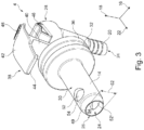
- connector 4 of 1 More details of connector 4 of 1 are based on the 3 and 4 explained, which show the connector 3 according to a second and third perspective.
- a further suction opening 52 ′ can be guided through the casing wall 30 .
- the additional suction opening 52' has an angular position that differs from the suction opening 52 and thus increases the effective cross-section through which the beverage is sucked out of the beverage bag 2 into the beverage channel 24.
- the further suction opening 52' also increases the reliability, because if the wall of the beverage bag 2 also lies over the suction opening 52 when sucking off the beverage liquid, the further suction opening 52' is also available.
- the angular position of the additional suction opening 52 ′ is preferably chosen such that it is radially opposite the suction opening 52 .
- the suction opening 52 and the further suction opening 52' are expediently designed to be congruent, so that the two suction openings 52, 52' can be formed using the same tool, such as a drill, slide or the like.
- suction opening 52 and the further suction opening 52 ′ are subsequently formed into the connection piece, they can be designed as a bore through the jacket wall 30 .
- a cross-sectional area of the suction port 52 defined in 4 is indicated by its diameter 60 can be chosen so that the stability of the connection piece 4 is sufficiently high in this area for the piercing process described above.
- cross-sectional areas between 10% and 30% of a cross-sectional area of the Beverage channel 24 proved to be suitable in 3 is indicated by its diameter 62.
- connection piece 4 is to provide two independent openings so that beverage liquid can be sucked out of the beverage bag 2 via one of the openings when the wall of the beverage bag 2 lies on the other of the openings.
- connection piece 4 is shown.
- connection thread is formed as an internal thread into the puncture tube 14 from the axial rear side 28 counter to the puncture direction 22 .
- This connection thread is from the perspective of figure 5 not to be seen.
- the axial opening 64 to the drinks channel 24 is partially covered by the spacer 54 so that the axial opening 64 is also protected against being covered by the wall of the drinks bag 2 .
- the wall should cover the axial opening 64 from a direction different from a direction of the suction openings 52, 52'.
Landscapes
- Engineering & Computer Science (AREA)
- General Engineering & Computer Science (AREA)
- Mechanical Engineering (AREA)
- Packages (AREA)
Claims (3)
- Pièce de raccordement (4) pour raccorder un tuyau (6) à un sac à boisson (2), comprenant :- un tube de perçage (14) avec un côté de perçage axial (26), un côté arrière axial (28) opposé au côté de perçage axial (26) et une paroi d'enveloppe (30) qui entoure un canal de boisson (24) dans une direction de perçage (22) vue depuis le côté arrière axial (28) vers le côté de perçage axial (26) et qui relie le côté de perçage axial (26) au côté arrière axial (28),- un raccord de tuyau (20) raccordé à la face arrière axiale (28) du tube de perçage (14) et menant dans le canal de boisson (24) pour le raccordement du tuyau (6),- une paroi de butée (32) disposée entre le raccord de tuyau (20) et le côté axial de pénétration (26) et dépassant radialement de la paroi d'enveloppe (30), qui limite une profondeur de pénétration (58) du tube de pénétration (14) dans le sachet de boisson (2), et- une ouverture d'aspiration (52) menant dans le canal de boisson (24), qui, vue dans la direction de pénétration (22), est disposée sur le tube de pénétration (14) avant la paroi de butée (32), et- une entretoise (54) s'étendant devant l'ouverture d'aspiration (52), vue dans la direction de piquage (22),- le tube de piquage (14) étant ouvert (64) sur le côté axial de piquage (26) vers le canal de boisson (24),
où- une surface de section transversale (60) de l'ouverture d'aspiration (52) est comprise entre 10% et 30% d'une surface de section transversale (62) du canal de boisson (2), et- une distance (56) de l'ouverture d'aspiration (52) par rapport au côté de perçage axial (26) du tube de perçage (14) est comprise entre 5% et 20% d'une distance (58) de la paroi de butée (32) par rapport au côté de perçage axial (26) du tube de perçage (14),- l'ouverture d'aspiration (52) et une autre ouverture d'aspiration (52') coïncidente, opposée radialement à l'ouverture d'aspiration (52), sont guidées à travers la paroi d'enveloppe (30),- les ouvertures d'aspiration (52, 52') sont réalisées sous forme de perçages à travers la paroi d'enveloppe (30). - Pièce de raccordement (4) selon la revendication 1, dans laquelle l'entretoise (54) est conçue comme une partie de la paroi d'enveloppe (30).
- Pièce de raccordement (4) selon l'une des revendications précédentes, dans laquelle la paroi d'enveloppe (30), vue dans la direction d'insertion (22), se rétrécit radialement dans une zone de guidage (49) derrière le côté axial d'insertion (26) et l'ouverture d'aspiration (52), vue dans la direction d'insertion (22), est disposée derrière la zone de guidage (49).
Priority Applications (1)
| Application Number | Priority Date | Filing Date | Title |
|---|---|---|---|
| EP19020027.9A EP3683483B1 (fr) | 2019-01-16 | 2019-01-16 | Pièce de raccordement permettant de raccorder un tuyau à un sachet de boisson |
Applications Claiming Priority (1)
| Application Number | Priority Date | Filing Date | Title |
|---|---|---|---|
| EP19020027.9A EP3683483B1 (fr) | 2019-01-16 | 2019-01-16 | Pièce de raccordement permettant de raccorder un tuyau à un sachet de boisson |
Publications (3)
| Publication Number | Publication Date |
|---|---|
| EP3683483A1 EP3683483A1 (fr) | 2020-07-22 |
| EP3683483C0 EP3683483C0 (fr) | 2023-08-09 |
| EP3683483B1 true EP3683483B1 (fr) | 2023-08-09 |
Family
ID=65041544
Family Applications (1)
| Application Number | Title | Priority Date | Filing Date |
|---|---|---|---|
| EP19020027.9A Active EP3683483B1 (fr) | 2019-01-16 | 2019-01-16 | Pièce de raccordement permettant de raccorder un tuyau à un sachet de boisson |
Country Status (1)
| Country | Link |
|---|---|
| EP (1) | EP3683483B1 (fr) |
Family Cites Families (8)
| Publication number | Priority date | Publication date | Assignee | Title |
|---|---|---|---|---|
| USRE32354E (en) * | 1980-07-21 | 1987-02-17 | Scholle Corporation | Container for holding and dispensing fluid |
| EP0585908A3 (fr) * | 1992-09-01 | 1995-02-15 | Praezisions Werkzeuge Ag | Réceptacles avec sachet interne. |
| CA2144494C (fr) * | 1994-03-31 | 2000-02-15 | Clark E. Harris | Chambre de precombustion |
| US5823397A (en) * | 1997-04-15 | 1998-10-20 | Masco Corporation | Personal hygiene liquids dispenser with an improved valve seat |
| DE19839842A1 (de) * | 1998-09-02 | 2000-03-09 | Arthur Steiger | Entnahmevorrichtung für einen Flüssigkeitsbehälter |
| NL1016292C2 (nl) * | 2000-09-28 | 2002-04-02 | Itsac Nv | Zak alsmede een afgiftesysteem omvattende een dergelijke zak en werkwijzen voor de vervaardiging en het vullen van een dergelijke zak. |
| CA2741643C (fr) | 2008-10-22 | 2016-01-12 | Scholle Corporation | Sac auto-obturant dans un ensemble bouchon de boite |
| US9573736B2 (en) | 2013-07-03 | 2017-02-21 | Scholle Ipn Corporation | Connector assembly for a self sealing fitment |
-
2019
- 2019-01-16 EP EP19020027.9A patent/EP3683483B1/fr active Active
Also Published As
| Publication number | Publication date |
|---|---|
| EP3683483A1 (fr) | 2020-07-22 |
| EP3683483C0 (fr) | 2023-08-09 |
Similar Documents
| Publication | Publication Date | Title |
|---|---|---|
| EP2667838B1 (fr) | Dispositif de liaison destiné à relier un premier réservoir à un deuxième réservoir | |
| EP0808148B1 (fr) | Dispositif de transfert | |
| DE602005000215T2 (de) | Eine sterile Verbindung herstellender Perforationsverbinder | |
| DE102012113002B4 (de) | Transfervorrichtung zur Entnahme oder Übergabe eines Fluids | |
| DE3029631C2 (de) | Sammelbehälter zur Aufnahme gefährlicher biologischer Flüssigkeiten | |
| AT514328B1 (de) | Transfervorrichtung | |
| EP0584396A1 (fr) | Raccord pour disconnecter et reconnecter l'écoulement d'un fluide | |
| WO1997015267A2 (fr) | Adaptateur utile pour prelever un liquide dans un recipient ferme par un bouchon | |
| EP2533832B1 (fr) | Connecteur pour récipient contenant un agent actif médical | |
| DE2258372B2 (de) | Füllbare Spritze | |
| CH433605A (de) | Einrichtung zum Mischen von zwei Stoffen und zum Füllen einer Spritze mit der Mischung | |
| DE2439392A1 (de) | Vorrichtung und verfahren zum aseptischen sammeln von fluiden durch unterdruck | |
| DE20016945U1 (de) | Entnahmespike | |
| EP2723648B1 (fr) | Dispositif de réception et de distribution d'un fluide | |
| DE29607437U1 (de) | Medizintechnische Anschlußvorrichtung | |
| DE102013012353B4 (de) | System zur Entnahme medizinischer Flüssigkeiten aus Behältern | |
| DE10048126B4 (de) | Vorrichtung zur Entnahme und/oder Dosierung von Flüssigkeitsproben mittels Unterdruck, insbesondere für analytische Untersuchungen | |
| WO2020249738A2 (fr) | Système de transfert de liquide et composants dédiés | |
| DE60224940T2 (de) | Sicherheitsverpackung für eine flasche für medizinische anwendungen | |
| EP3683483B1 (fr) | Pièce de raccordement permettant de raccorder un tuyau à un sachet de boisson | |
| WO2020221381A1 (fr) | Système de transfert médical | |
| EP0343534B1 (fr) | Récipient pour conserver des liquides, en particulier des liquides corporels | |
| EP2465557A1 (fr) | Dispositif pour la sortie d'un liquide à partir d'un récipient | |
| DE19604113C2 (de) | Einkammer-Transfersystem für Wirksubstanzen, und der daraus fertig montierte Transferbehälter | |
| DE102023121607A1 (de) | Medizinischer Spike mit Ausgasungsschutz |
Legal Events
| Date | Code | Title | Description |
|---|---|---|---|
| PUAI | Public reference made under article 153(3) epc to a published international application that has entered the european phase |
Free format text: ORIGINAL CODE: 0009012 |
|
| STAA | Information on the status of an ep patent application or granted ep patent |
Free format text: STATUS: THE APPLICATION HAS BEEN PUBLISHED |
|
| AK | Designated contracting states |
Kind code of ref document: A1 Designated state(s): AL AT BE BG CH CY CZ DE DK EE ES FI FR GB GR HR HU IE IS IT LI LT LU LV MC MK MT NL NO PL PT RO RS SE SI SK SM TR |
|
| AX | Request for extension of the european patent |
Extension state: BA ME |
|
| STAA | Information on the status of an ep patent application or granted ep patent |
Free format text: STATUS: REQUEST FOR EXAMINATION WAS MADE |
|
| 17P | Request for examination filed |
Effective date: 20210122 |
|
| RBV | Designated contracting states (corrected) |
Designated state(s): AL AT BE BG CH CY CZ DE DK EE ES FI FR GB GR HR HU IE IS IT LI LT LU LV MC MK MT NL NO PL PT RO RS SE SI SK SM TR |
|
| STAA | Information on the status of an ep patent application or granted ep patent |
Free format text: STATUS: EXAMINATION IS IN PROGRESS |
|
| 17Q | First examination report despatched |
Effective date: 20220613 |
|
| GRAP | Despatch of communication of intention to grant a patent |
Free format text: ORIGINAL CODE: EPIDOSNIGR1 |
|
| STAA | Information on the status of an ep patent application or granted ep patent |
Free format text: STATUS: GRANT OF PATENT IS INTENDED |
|
| RIC1 | Information provided on ipc code assigned before grant |
Ipc: F16L 37/096 20060101ALN20230223BHEP Ipc: B65D 77/06 20060101ALI20230223BHEP Ipc: F16L 37/098 20060101AFI20230223BHEP |
|
| INTG | Intention to grant announced |
Effective date: 20230313 |
|
| GRAS | Grant fee paid |
Free format text: ORIGINAL CODE: EPIDOSNIGR3 |
|
| GRAA | (expected) grant |
Free format text: ORIGINAL CODE: 0009210 |
|
| STAA | Information on the status of an ep patent application or granted ep patent |
Free format text: STATUS: THE PATENT HAS BEEN GRANTED |
|
| AK | Designated contracting states |
Kind code of ref document: B1 Designated state(s): AL AT BE BG CH CY CZ DE DK EE ES FI FR GB GR HR HU IE IS IT LI LT LU LV MC MK MT NL NO PL PT RO RS SE SI SK SM TR |
|
| REG | Reference to a national code |
Ref country code: GB Ref legal event code: FG4D Free format text: NOT ENGLISH |
|
| REG | Reference to a national code |
Ref country code: CH Ref legal event code: EP |
|
| REG | Reference to a national code |
Ref country code: DE Ref legal event code: R096 Ref document number: 502019008819 Country of ref document: DE |
|
| REG | Reference to a national code |
Ref country code: IE Ref legal event code: FG4D Free format text: LANGUAGE OF EP DOCUMENT: GERMAN |
|
| U01 | Request for unitary effect filed |
Effective date: 20230905 |
|
| U07 | Unitary effect registered |
Designated state(s): AT BE BG DE DK EE FI FR IT LT LU LV MT NL PT SE SI Effective date: 20230908 |
|
| PG25 | Lapsed in a contracting state [announced via postgrant information from national office to epo] |
Ref country code: GR Free format text: LAPSE BECAUSE OF FAILURE TO SUBMIT A TRANSLATION OF THE DESCRIPTION OR TO PAY THE FEE WITHIN THE PRESCRIBED TIME-LIMIT Effective date: 20231110 |
|
| PG25 | Lapsed in a contracting state [announced via postgrant information from national office to epo] |
Ref country code: IS Free format text: LAPSE BECAUSE OF FAILURE TO SUBMIT A TRANSLATION OF THE DESCRIPTION OR TO PAY THE FEE WITHIN THE PRESCRIBED TIME-LIMIT Effective date: 20231209 |
|
| PG25 | Lapsed in a contracting state [announced via postgrant information from national office to epo] |
Ref country code: RS Free format text: LAPSE BECAUSE OF FAILURE TO SUBMIT A TRANSLATION OF THE DESCRIPTION OR TO PAY THE FEE WITHIN THE PRESCRIBED TIME-LIMIT Effective date: 20230809 Ref country code: NO Free format text: LAPSE BECAUSE OF FAILURE TO SUBMIT A TRANSLATION OF THE DESCRIPTION OR TO PAY THE FEE WITHIN THE PRESCRIBED TIME-LIMIT Effective date: 20231109 Ref country code: IS Free format text: LAPSE BECAUSE OF FAILURE TO SUBMIT A TRANSLATION OF THE DESCRIPTION OR TO PAY THE FEE WITHIN THE PRESCRIBED TIME-LIMIT Effective date: 20231209 Ref country code: HR Free format text: LAPSE BECAUSE OF FAILURE TO SUBMIT A TRANSLATION OF THE DESCRIPTION OR TO PAY THE FEE WITHIN THE PRESCRIBED TIME-LIMIT Effective date: 20230809 Ref country code: GR Free format text: LAPSE BECAUSE OF FAILURE TO SUBMIT A TRANSLATION OF THE DESCRIPTION OR TO PAY THE FEE WITHIN THE PRESCRIBED TIME-LIMIT Effective date: 20231110 |
|
| PG25 | Lapsed in a contracting state [announced via postgrant information from national office to epo] |
Ref country code: PL Free format text: LAPSE BECAUSE OF FAILURE TO SUBMIT A TRANSLATION OF THE DESCRIPTION OR TO PAY THE FEE WITHIN THE PRESCRIBED TIME-LIMIT Effective date: 20230809 |
|
| U20 | Renewal fee for the european patent with unitary effect paid |
Year of fee payment: 6 Effective date: 20240126 |
|
| PG25 | Lapsed in a contracting state [announced via postgrant information from national office to epo] |
Ref country code: ES Free format text: LAPSE BECAUSE OF FAILURE TO SUBMIT A TRANSLATION OF THE DESCRIPTION OR TO PAY THE FEE WITHIN THE PRESCRIBED TIME-LIMIT Effective date: 20230809 |
|
| PG25 | Lapsed in a contracting state [announced via postgrant information from national office to epo] |
Ref country code: SM Free format text: LAPSE BECAUSE OF FAILURE TO SUBMIT A TRANSLATION OF THE DESCRIPTION OR TO PAY THE FEE WITHIN THE PRESCRIBED TIME-LIMIT Effective date: 20230809 Ref country code: RO Free format text: LAPSE BECAUSE OF FAILURE TO SUBMIT A TRANSLATION OF THE DESCRIPTION OR TO PAY THE FEE WITHIN THE PRESCRIBED TIME-LIMIT Effective date: 20230809 Ref country code: ES Free format text: LAPSE BECAUSE OF FAILURE TO SUBMIT A TRANSLATION OF THE DESCRIPTION OR TO PAY THE FEE WITHIN THE PRESCRIBED TIME-LIMIT Effective date: 20230809 Ref country code: CZ Free format text: LAPSE BECAUSE OF FAILURE TO SUBMIT A TRANSLATION OF THE DESCRIPTION OR TO PAY THE FEE WITHIN THE PRESCRIBED TIME-LIMIT Effective date: 20230809 Ref country code: SK Free format text: LAPSE BECAUSE OF FAILURE TO SUBMIT A TRANSLATION OF THE DESCRIPTION OR TO PAY THE FEE WITHIN THE PRESCRIBED TIME-LIMIT Effective date: 20230809 |
|
| REG | Reference to a national code |
Ref country code: DE Ref legal event code: R097 Ref document number: 502019008819 Country of ref document: DE |
|
| PLBE | No opposition filed within time limit |
Free format text: ORIGINAL CODE: 0009261 |
|
| STAA | Information on the status of an ep patent application or granted ep patent |
Free format text: STATUS: NO OPPOSITION FILED WITHIN TIME LIMIT |
|
| 26N | No opposition filed |
Effective date: 20240513 |
|
| PG25 | Lapsed in a contracting state [announced via postgrant information from national office to epo] |
Ref country code: MC Free format text: LAPSE BECAUSE OF FAILURE TO SUBMIT A TRANSLATION OF THE DESCRIPTION OR TO PAY THE FEE WITHIN THE PRESCRIBED TIME-LIMIT Effective date: 20230809 |
|
| PG25 | Lapsed in a contracting state [announced via postgrant information from national office to epo] |
Ref country code: MC Free format text: LAPSE BECAUSE OF FAILURE TO SUBMIT A TRANSLATION OF THE DESCRIPTION OR TO PAY THE FEE WITHIN THE PRESCRIBED TIME-LIMIT Effective date: 20230809 |
|
| REG | Reference to a national code |
Ref country code: CH Ref legal event code: PL |
|
| GBPC | Gb: european patent ceased through non-payment of renewal fee |
Effective date: 20240116 |
|
| PG25 | Lapsed in a contracting state [announced via postgrant information from national office to epo] |
Ref country code: GB Free format text: LAPSE BECAUSE OF NON-PAYMENT OF DUE FEES Effective date: 20240116 |
|
| PG25 | Lapsed in a contracting state [announced via postgrant information from national office to epo] |
Ref country code: CH Free format text: LAPSE BECAUSE OF NON-PAYMENT OF DUE FEES Effective date: 20240131 |
|
| PG25 | Lapsed in a contracting state [announced via postgrant information from national office to epo] |
Ref country code: GB Free format text: LAPSE BECAUSE OF NON-PAYMENT OF DUE FEES Effective date: 20240116 Ref country code: CH Free format text: LAPSE BECAUSE OF NON-PAYMENT OF DUE FEES Effective date: 20240131 |
|
| PG25 | Lapsed in a contracting state [announced via postgrant information from national office to epo] |
Ref country code: IE Free format text: LAPSE BECAUSE OF NON-PAYMENT OF DUE FEES Effective date: 20240116 |
|
| PG25 | Lapsed in a contracting state [announced via postgrant information from national office to epo] |
Ref country code: IE Free format text: LAPSE BECAUSE OF NON-PAYMENT OF DUE FEES Effective date: 20240116 |
|
| U20 | Renewal fee for the european patent with unitary effect paid |
Year of fee payment: 7 Effective date: 20250130 |
|
| PG25 | Lapsed in a contracting state [announced via postgrant information from national office to epo] |
Ref country code: CY Free format text: LAPSE BECAUSE OF FAILURE TO SUBMIT A TRANSLATION OF THE DESCRIPTION OR TO PAY THE FEE WITHIN THE PRESCRIBED TIME-LIMIT; INVALID AB INITIO Effective date: 20190116 |
|
| PG25 | Lapsed in a contracting state [announced via postgrant information from national office to epo] |
Ref country code: HU Free format text: LAPSE BECAUSE OF FAILURE TO SUBMIT A TRANSLATION OF THE DESCRIPTION OR TO PAY THE FEE WITHIN THE PRESCRIBED TIME-LIMIT; INVALID AB INITIO Effective date: 20190116 |
|
| PG25 | Lapsed in a contracting state [announced via postgrant information from national office to epo] |
Ref country code: TR Free format text: LAPSE BECAUSE OF FAILURE TO SUBMIT A TRANSLATION OF THE DESCRIPTION OR TO PAY THE FEE WITHIN THE PRESCRIBED TIME-LIMIT Effective date: 20230809 |
|
| U20 | Renewal fee for the european patent with unitary effect paid |
Year of fee payment: 8 Effective date: 20260120 |