EP3683484B1 - Rohrkoppelsystem - Google Patents
Rohrkoppelsystem Download PDFInfo
- Publication number
- EP3683484B1 EP3683484B1 EP20150669.8A EP20150669A EP3683484B1 EP 3683484 B1 EP3683484 B1 EP 3683484B1 EP 20150669 A EP20150669 A EP 20150669A EP 3683484 B1 EP3683484 B1 EP 3683484B1
- Authority
- EP
- European Patent Office
- Prior art keywords
- pipe
- connecting pipe
- coupling system
- sleeve
- securing sleeve
- Prior art date
- Legal status (The legal status is an assumption and is not a legal conclusion. Google has not performed a legal analysis and makes no representation as to the accuracy of the status listed.)
- Active
Links
Images


Classifications
-
- F—MECHANICAL ENGINEERING; LIGHTING; HEATING; WEAPONS; BLASTING
- F16—ENGINEERING ELEMENTS AND UNITS; GENERAL MEASURES FOR PRODUCING AND MAINTAINING EFFECTIVE FUNCTIONING OF MACHINES OR INSTALLATIONS; THERMAL INSULATION IN GENERAL
- F16L—PIPES; JOINTS OR FITTINGS FOR PIPES; SUPPORTS FOR PIPES, CABLES OR PROTECTIVE TUBING; MEANS FOR THERMAL INSULATION IN GENERAL
- F16L21/00—Joints with sleeve or socket
-
- F—MECHANICAL ENGINEERING; LIGHTING; HEATING; WEAPONS; BLASTING
- F16—ENGINEERING ELEMENTS AND UNITS; GENERAL MEASURES FOR PRODUCING AND MAINTAINING EFFECTIVE FUNCTIONING OF MACHINES OR INSTALLATIONS; THERMAL INSULATION IN GENERAL
- F16L—PIPES; JOINTS OR FITTINGS FOR PIPES; SUPPORTS FOR PIPES, CABLES OR PROTECTIVE TUBING; MEANS FOR THERMAL INSULATION IN GENERAL
- F16L37/00—Couplings of the quick-acting type
- F16L37/26—Couplings of the quick-acting type in which the connection is made by transversely moving the parts together, with or without their subsequent rotation
-
- D—TEXTILES; PAPER
- D06—TREATMENT OF TEXTILES OR THE LIKE; LAUNDERING; FLEXIBLE MATERIALS NOT OTHERWISE PROVIDED FOR
- D06F—LAUNDERING, DRYING, IRONING, PRESSING OR FOLDING TEXTILE ARTICLES
- D06F57/00—Supporting means, other than simple clothes-lines, for linen or garments to be dried or aired
-
- D—TEXTILES; PAPER
- D06—TREATMENT OF TEXTILES OR THE LIKE; LAUNDERING; FLEXIBLE MATERIALS NOT OTHERWISE PROVIDED FOR
- D06F—LAUNDERING, DRYING, IRONING, PRESSING OR FOLDING TEXTILE ARTICLES
- D06F58/00—Domestic laundry dryers
- D06F58/10—Drying cabinets or drying chambers having heating or ventilating means
-
- D—TEXTILES; PAPER
- D06—TREATMENT OF TEXTILES OR THE LIKE; LAUNDERING; FLEXIBLE MATERIALS NOT OTHERWISE PROVIDED FOR
- D06F—LAUNDERING, DRYING, IRONING, PRESSING OR FOLDING TEXTILE ARTICLES
- D06F58/00—Domestic laundry dryers
- D06F58/20—General details of domestic laundry dryers
-
- D—TEXTILES; PAPER
- D06—TREATMENT OF TEXTILES OR THE LIKE; LAUNDERING; FLEXIBLE MATERIALS NOT OTHERWISE PROVIDED FOR
- D06F—LAUNDERING, DRYING, IRONING, PRESSING OR FOLDING TEXTILE ARTICLES
- D06F59/00—Supports adapted to retain the shape of particular articles being dried, e.g. incorporating heating means
Definitions
- the invention relates to a pipe coupling system and a drying device which includes the pipe coupling system according to the invention.
- Drying devices or drying systems are known in the prior art for drying objects such as items of clothing in particular.
- Such known devices usually include at least one drying tube, which is adapted in its shape or in its course to the item of clothing to be dried.
- the drying tube has a plurality of air outlet openings, through which compressed air, optionally heated, can escape through the tube in order to dry the garment from the inside.
- the pipe coupling system described here comprises two pieces of pipe, one piece of pipe having a coupling element and the other piece of pipe having a receptacle for the coupling element.
- the connection between the two pieces of pipe can be secured with a slip-on sleeve, the sleeve being held in position by sealing rings in contact with the pieces of pipe.
- the invention relates to a pipe coupling system, in particular for a drying system, comprising a first connecting pipe, a second connecting pipe that can be connected to the first connecting pipe via a connecting element, and a securing sleeve, the connecting element being insertable into a receiving area of the first connecting pipe, and the securing sleeve being displaceable over the first connection pipe is arranged in such a way that the securing sleeve can be positioned over the receiving area
- the securing sleeve has an insertion area on its inner wall, in which a on the outside of the first Connecting pipe or the second connecting pipe arranged latching element can be inserted or introduced.
- the interaction of the insertion area and the latching element creates a wear-free construction of the securing mechanism that is not dependent on the frictional effect of an element, such as a sealing ring in particular.
- the securing sleeve is preferably designed as a tubular structure or as a tubular element.
- the inner diameter of the securing sleeve is preferably only slightly larger than the outer diameter of the connecting pipe on which the latching element for the insertion area of the securing sleeve is provided.
- the inside diameter of the securing sleeve can optionally be between 0.01 mm and 0.5 mm larger than the outside diameter of the connecting pipe.
- outer diameter of the connecting pipe relates in particular to the widest point of that area of the connecting pipe or connecting pipes over which the securing sleeve is to be moved. This means that the first or the second connecting tube can have a larger outer diameter in certain areas if the locking sleeve is not intended to be moved over that area. If necessary, a widening of the connecting tube can also serve as a sleeve stop in order to limit the mobility of the securing sleeve.
- internal diameter of the locking sleeve refers to that area of the locking sleeve in which no insertion area is provided, ie in particular the smallest diameter of a circular cross section of the locking sleeve.
- the parameters of the lead-in area are referred to as "depth" and "height" in the context of the present invention.
- the depth refers to the extent of the insertion area, which preferably runs parallel to the central axis or to the main direction of extent of the securing sleeve.
- the depth is preferably smaller than the sleeve length, whereby a sleeve stop is formed inside the locking sleeve, so that the locking sleeve can only be moved to a limited extent in the direction of the other connection pipe, namely only until the locking element comes into contact with the sleeve stop.
- the height of the insertion area denotes the height of the insertion area in the wall of the securing sleeve.
- the height is preferably less than the thickness of the wall locking sleeve.
- the insertion area has a height which corresponds to the thickness of the wall. The insertion area can therefore be covered at the top by part of the wall, but it can also be open at the top.
- the aforementioned depth is preferably dimensioned such that the securing sleeve covers the receiving area in the locked position or prevents the connecting element from slipping out of the receiving area.
- the engagement means is preferably suitably positioned on the first connection pipe.
- the locking element is designed as a pin.
- the insertion area is designed as a groove.
- the latching element is preferably designed as a pin.
- the groove can run on the inner circumference of the locking sleeve. According to the invention, the groove runs parallel to the main extension direction of the securing sleeve or to the length of the sleeve.
- the latching element can also comprise more than one pin, in which case the implementation of the insertion area can be designed accordingly in order to be able to accommodate the latching element.
- the latching element is designed as a retaining ring that partially or completely radially encircles the first connecting tube, or that the latching element is designed as a projection of the first connecting tube or the second connecting tube.
- the retaining ring or projection may form a sleeve stop.
- the retaining ring or projection can preferably have a larger diameter than the inner diameter of the locking sleeve.
- the insertion area is designed as a fold that partially or completely surrounds the inner circumference of the securing sleeve.
- the receiving area includes a retaining groove that partially encircles the inner circumference of the first connecting pipe, and that the Connecting element is designed as a collar, wherein the collar is designed such that it can be inserted into the retaining groove.
- the length of the insertion area is greater than the distance between the latching element and the receiving area.
- the shape of the insertion area can be chosen by a person skilled in the art according to the possibilities and it is preferably adapted to the shape of the latching element.
- the cross-sectional shape of a groove can therefore, if appropriate, correspond to the shape of the latching element, in particular a pin.
- the shape of the groove cross section and the shape of the latching element can in particular be rectangular, square, semicircular or arcuate.
- the engagement means is hemispherical, in which case the cross-section of the groove can be semicircular.
- the engagement of the connecting element and the corresponding receiving area is preferably designed in such a way that the interior of the first connecting pipe and the second connecting pipe are arranged in alignment, as a result of which the air flow can flow through the connecting area unhindered.
- the inner wall of the first connecting pipe is arranged flush with the inner wall of the second connecting pipe when the connecting element is in the fully inserted position in the receiving area.
- a stop is preferably provided on that side of the connecting pipe which is opposite the receiving area, in order to prevent the latching element from slipping out of the groove.
- the stop can be designed as a stop means, for example as a projection, but alternatively also as a widening of the connecting tube.
- the stop is preferably formed by a distributor pipe to which the first connection pipe is attached.
- the connection between the first connecting pipe and the connecting pipe is preferably established by a threaded connection.
- first connecting pipe or the second connecting pipe can be arranged or is arranged on a distributor pipe, the main direction of extent of the distributor pipe running orthogonally to the main direction of extent of the first connecting pipe or the second connecting pipe.
- the distributor tube forms a stop for the securing sleeve, the distance between the latching element and the stop being smaller than the length of the sleeve.
- the connecting pipe which can be connected or is connected to the distributor pipe comprises a thread for the detachable connection to the distributor pipe.
- the engagement of the connecting element in the receiving area can, if necessary, essentially be effected by any connection known in the prior art, which enables the connection of two tubular elements by laterally inserting a connecting element into a receiving area.
- the receiving area is preferably designed as a groove that partially encircles the inner circumference of the first connecting pipe, the shape and dimensions of which are adapted to a collar or some other shape of the connecting element.
- An insertion opening which opens the receiving area to the outside, is preferably provided for inserting and removing the connecting element from the receiving area.
- sealing elements can be provided in the receiving area or on the connecting element, but this is not a necessary feature. If only air is passed through the connection, the connection is sufficiently tight even without the use of seals. If the connection is also used to transport liquids, a seal can be advantageous.
- a drying pipe is arranged on the second connecting pipe, which drying pipe is preferably connected or can be connected to the second connecting pipe via one or more plug connections.
- the drying tube has at least one, preferably several, air outlet openings through which air can flow out. That Drying tube may take various forms known to those skilled in the art. If a drying device with the pipe coupling system according to the invention is used for drying items of clothing, the drying pipe can, for example, essentially have the shape of the item of clothing to be dried. If the drying pipe is provided, for example, for drying a full body suit, the drying pipe can have elements that are inserted into the arm and leg areas and into the torso area of the full body suit. As a result, the drying tube can also act as a device similar to a clothes hanger.
- a drying tube can be or is arranged on the first connecting tube or on the second connecting tube, with the drying tube comprising at least one air outlet opening.
- drying pipe can be releasably connected to the first connecting pipe or the second connecting pipe via a plug connection.
- the first receiving pipe can be connected or can be connected to a distributor pipe, in which case the second receiving pipe is or can be connected to the drying pipe.
- the second receiving pipe can also be connected or can be connected to a distribution pipe, in which case the first receiving pipe is or can be connected to the drying pipe.
- the locking element is preferably arranged on that connection pipe which is connected or can be connected to the distributor pipe.
- the latching element is preferably arranged on the first connection pipe if the first connection pipe can be connected or is connected to the distributor pipe. Accordingly, the drying pipe is preferably connected or can be connected to the second connection pipe. It is therefore preferred that the latching element is arranged on that connection pipe which is located at the top when the pipe coupling system is used as intended. This means that the locking sleeve is moved into the locked position by gravity.
- the securing sleeve would be moved into the release position by the effect of gravity.
- a holding means such as an internal sealing ring, would have to be provided in order to permanently hold the locking sleeve in the locked position.
- the receiving area comprises an insertion opening for inserting the connecting element.
- the securing sleeve can be moved between a release position and a blocking position, the securing sleeve releasing the connection area in the release position, and the securing sleeve being arranged at least partially over the connection area in the blocking position.
- a sleeve stop is provided, the length of the insertion area being smaller than the sleeve length of the securing sleeve.
- the locking element is arranged on the first connection pipe, that the first connection pipe is connected or can be connected to the distributor pipe, and that the drying pipe can be arranged or is arranged on the second connection pipe.
- the invention also relates to a drying device comprising a pipe coupling system according to the invention.
- a plurality of distributor pipes can optionally be provided, to which a plurality of first and second connecting pipes are preferably attached.
- a drying device preferably provides air at increased pressure, which is conducted via the distribution pipe via the first connection pipe and the second connection pipe into the drying pipe, where the air can exit via the air outlet openings.
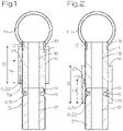
- FIG. 1 shows a schematic lateral sectional view of a pipe coupling system according to the invention in the connected state with the securing sleeve 4 in the release position
- 2 shows the pipe coupling system according to the invention in the connected state with the locking sleeve 4 in the locked position.
- the Figures 1 and 2 show the device according to the invention according to a first embodiment.
- the Figures 1 and 2 show the first connecting pipe 1, which is connected via a thread 19 to the connecting pipe 11 of a drying device in an air-conducting manner.
- the first connection pipe 1 At its end opposite the thread 19, the first connection pipe 1 a receiving area 5 which is designed in the form of a holding groove 9 .
- the retaining groove 9 partially runs around the inner circumference of the first connecting pipe 1 , an insertion opening 18 for inserting a connecting element 2 into the retaining groove 9 being provided.
- the main extension direction of the connecting pipe 11 runs essentially orthogonally to the main extension direction of the first connecting pipe 1 and the second connecting pipe 3.
- the main extension direction of the connecting pipe 11 runs out of the plane of the drawing.
- a securing sleeve 4 is provided in order to be able to secure the connection between the first connecting pipe 1 and the second connecting pipe 3 .
- the securing sleeve 4 is dimensioned in such a way that it completely encloses the first connecting pipe 1 and the second connecting pipe 3 .
- the inner diameter of the securing sleeve 4 is slightly larger than the outer diameter of the first connecting pipe 1, with a slight amount of play being provided for easier displacement of the securing sleeve 4.
- the inside diameter of the securing sleeve 4 is approximately 0.1 mm larger than the outside diameter of the first connecting pipe 1 .
- the insertion area is in this Embodiment designed as a groove 22.
- the groove 22 runs from an edge of the securing sleeve 4, the depth 14 of the insertion area 6 being determined by the overall length of the groove 22.
- the groove 22 runs perpendicularly, i.e. essentially parallel to the main direction of extent of the securing sleeve 4.
- the securing sleeve 4 has a sleeve length 13 , the sleeve length 13 being essentially determined by the normal distance between two opposite edges of the securing sleeve 4 .
- the depth 14 of the insertion area 6 is smaller than the sleeve length 13, which means that the groove 22 does not extend over the entire length of the securing sleeve 4.
- An engagement means 7 which engages in the groove 22 is provided on the outer surface of the first connecting pipe 1 .
- the engagement means 7 is designed as a pin 8 .
- the engagement means 7 can also be designed in other forms as long as it can engage in the groove 22 of the securing sleeve 4 .
- the height of the groove 6 corresponds to the height of the pin 6.
- FIG. 1 shows the pipe coupling system according to the invention with the securing sleeve 4 in the release position, the distribution pipe 11 into which the first connecting pipe 1 is screwed serving as a stop 12 for the securing sleeve 4 .
- the distance between the stop 12 and the latching element 7 is designed in such a way that the latching element 7 cannot slip out of the groove 22 .
- the distance between the stop 12 and the locking element 7 is therefore smaller than the sleeve length 13.
- the securing sleeve 4 completely releases the receiving area 5 of the first connecting pipe 1, as a result of which the connection between the first connecting pipe 1 and the second connecting pipe 3 can be released. This is done by pulling the connecting element 2 out of the receiving area 5.
- the securing sleeve 4 is preferably held in the release position by hand, since it would immediately slip into the blocked position due to the effect of gravity in the arrangement shown.
- the safety sleeve 4 If the safety sleeve 4 is released, it slides down into the locked position, which 2 is shown.
- the securing sleeve 4 can move down as far as the depth 14 of the insertion area 6 dictates. A further downward movement of the securing sleeve 4 is prevented by the sleeve stop 21 on the inside of the securing sleeve 4 .
- the securing sleeve 4 covers the receiving area 5 into which the connecting element 2 is inserted. Since the securing sleeve 4 completely surrounds the receiving area 5 , the connecting element 2 is prevented from slipping out of the receiving area 5 . This enables a stable connection between the first connection pipe 1 and the second connection pipe 3 .
- the securing sleeve 4 must be moved back into a position in which the receiving area 5 is released. This can be the in 1 shown release position, but also any other position in which the connection between the connecting element 2 and the receiving area 5 can be released.
- FIG 3 shows a schematic lateral sectional view of a first connection pipe 1 of the pipe coupling system according to the invention, the insertion opening 18 and the retaining groove 9 of the receiving area 5 being shown.
- the thread 19 is shown, which is designed for screwing the first connection pipe 1 into a distributor pipe 11 .
- the inner wall of the connecting pipe 16 extends between the receiving area 5 and the thread 19.
- FIG. 12 shows a schematic plan view of the first connection pipe 1.
- FIG 3 wherein the insertion opening 18 and the retaining groove 9 of the receiving area 5 are shown schematically.
- FIG 5 shows a schematic lateral sectional view of a second connection pipe 3 of the pipe coupling system according to the invention, to which a drying pipe 15 is connected.
- the second connection pipe 3 has a connecting element 2 at its upper end, which is designed as a collar 10 .
- the connecting element 2 is designed to be inserted into the corresponding receiving area 5 of a first connecting pipe 1 .
- the drying pipe 15 is connected to the second connecting pipe 3 via a plug connection 20 .
- the drying tube 15 is in the figure 5 not shown in detail. It can have different shapes for holding different objects, especially items of clothing. In any case, the drying tube 15 has at least one, preferably several, air outlet openings, from which the air provided by an air supply device can escape.
- figure 6 shows a schematic side sectional view of another example of a pipe coupling system in the connected state with the locking sleeve 4 in the release position, while 7 shows the same embodiment with locking sleeve 4 in the locked position.
- the insertion area 6 is formed by a fold 24 which is formed completely around the inner diameter of the securing sleeve 4 .
- the latching element 7 which in the locked position is in operative connection with the insertion area 6 or with the sleeve stop 21 , is designed in this example as a retaining ring 23 which is designed to completely encircle the outer diameter of the first connecting pipe 1 .
- the height of the retaining ring 23 essentially corresponds to the height of the fold 24.
Landscapes
- Engineering & Computer Science (AREA)
- General Engineering & Computer Science (AREA)
- Mechanical Engineering (AREA)
- Quick-Acting Or Multi-Walled Pipe Joints (AREA)
Description
- Die Erfindung betrifft ein Rohrkoppelsystem, sowie eine Trocknungsvorrichtung, welche das erfindungsgemäße Rohrkoppelsystem umfasst.
- Trocknungsvorrichtungen bzw. Trocknungsanlagen sind im Stand der Technik für das Trocknen von Gegenständen wie insbesondere Kleidungsstücken bekannt. Derartige bekannte Vorrichtungen umfassen üblicherweise wenigstens ein Trocknungsrohr, welches in seiner Form bzw. in seinem Verlauf an das zu trocknende Kleidungsstück angepasst ist. Das Trocknungsrohr weist mehrere Luftauslassöffnungen auf, durch welche durch das Rohr geleitete, gegebenenfalls erwärmte, Druckluft entweichen kann, um so das Kleidungsstück von innen zu trocknen.
- Um ein bereits getrocknetes Kleidungsstück in effizienter Weise von der Trocknungsvorrichtung entfernen zu können, ist es im Stand der Technik bekannt, das Kleidungsstück mitsamt dem Trocknungsrohr von der Trocknungsvorrichtung abzunehmen, womit das Trocknungsrohr weiterhin als eine Art Kleiderbügel verwendet wird. Gleichzeitig wird dadurch an der Trocknungsvorrichtung Platz für ein weiteres Kleidungsstück geschaffen.
- Um die Verbindung des Trocknungsrohres mit der Trocknungsvorrichtung zu verbessern, wurden im Stand der Technik bereits Rohrkoppelsysteme für einen derartigen Einsatz vorgeschlagen. Ein solches Rohrkoppelsystem wird in der österreichischen Patentanmeldung
AT 516 342 A1 - Derartige Dichtungsringe halten die Hülse immer in einer festen Position, weshalb beim Verschieben der Hülse ein erhöhter Kraftaufwand möglich sein kann. Ferner kann das Verschieben der Hülse dadurch erschwert werden, wenn der Benutzer beispielsweise nur eine Hand frei hat. Andere Rohrverbindungssysteme sind beispielsweise aus der
US 3092403 A bekannt. Dort geoffenbarte Sicherungshülsen sind mit einem Gewinde oder einer ringförmigen Kupplung an einem Rohr befestigbar. Auch diese Verbindungen sind nicht einfach einhändig betätigbar. - Es ist eine Aufgabe der vorliegenden Erfindung, diesen Nachteil des Standes der Technik zu überwinden und ein Rohrkoppelsystem zu schaffen, welches nicht den Einsatz einer Hülse mit einem Dichtungsring erfordert.
- Die Aufgabe der Erfindung wird durch das kennzeichnende Merkmal des unabhängigen Patentanspruchs gelöst. Weitere Merkmale von bevorzugten Ausführungsformen der Erfindung ergeben sich aus den abhängigen Patentansprüchen, den Figuren, sowie aus den Ausführungsbeispielen.
- Die Erfindung betrifft ein Rohrkoppelsystem, insbesondere für eine Trocknungsanlage, umfassend ein erstes Anschlussrohr, ein mit dem ersten Anschlussrohr über ein Verbindungselement verbindbares zweites Anschlussrohr, sowie eine Sicherungshülse, wobei das Verbindungselement in einen Aufnahmebereich des ersten Anschlussrohrs einführbar ist, und wobei die Sicherungshülse verschiebbar über dem ersten Anschlussrohr derart angeordnet ist, dass die Sicherungshülse über dem Aufnahmebereich positionierbar ist
- Erfindungsgemäß ist vorgesehen, dass die Sicherungshülse an ihrer Innenwandung einen Einführbereich aufweist, in welchen ein an der Außenseite des ersten Anschlussrohrs oder des zweiten Anschlussrohrs angeordnetes Rastelement einführbar oder eingeführt ist.
- Durch das Zusammenwirken aus Einführbereich und Rastelement wird eine verschleißfreie Konstruktion des Sicherungsmechanismus geschaffen, welche nicht von der Reibungswirkung eines Elements, wie insbesondere eines Dichtungsrings, abhängig ist. Die Sicherungshülse ist bevorzugt als rohrförmige Struktur oder als rohrförmiges Element ausgebildet. Der Innendurchmesser der Sicherungshülse ist bevorzugt nur etwas größer als der Außendurchmesser des Anschlussrohrs, auf welchem das Rastelement für den Einführbereich der Sicherungshülse vorgesehen ist. Dabei kann der Innendurchmesser der Sicherungshülse gegebenenfalls zwischen 0,01 mm und 0,5 mm größer sein als der Außendurchmesser des Anschlussrohrs. Der Begriff "Außendurchmesser des Anschlussrohrs" bezieht sich insbesondere auf die breiteste Stelle jenes Bereichs des Anschlussrohrs bzw. der Anschlussrohre, über welchen die Sicherungshülse bewegt werden soll. Dies bedeutet, dass das erste oder das zweite Anschlussrohr in bestimmten Bereichen einen größeren Außendurchmesser aufweisen kann, wenn nicht vorgesehen ist, dass die Sicherungshülse über jenen Bereich bewegt wird. Gegebenenfalls kann eine Verbreiterung des Anschlussrohrs auch als Hülsenanschlag dienen, um die Bewegbarkeit der Sicherungshülse zu begrenzen. Der Begriff "Innendurchmesser der Sicherungshülse" bezieht sich auf jenen Bereich der Sicherungshülse, in welchem kein Einführbereich vorgesehen ist, also insbesondere den kleinesten Durchmesser eines kreisförmigen Querschnitts der Sicherungshülse.
- Die Parameter des Einführbereichs werden in Zusammenhang mit der vorliegenden Erfindung als "Tiefe" und "Höhe" bezeichnet. Die Tiefe bezeichnet die Erstreckungstiefe des Einführbereichs, welche bevorzugt parallel zur Zentralachse bzw. zur Haupterstreckungsrichtung der Sicherungshülse verläuft. Bevorzugt ist die Tiefe kleiner als die Hülsenlänge, wodurch ein Hülsenanschlag im Inneren der Sicherungshülse gebildet wird, sodass die Sicherungshülse nur in begrenztem Maße in Richtung des jeweils anderen Anschlussrohrs bewegt werden kann, nämlich nur soweit, bis das Rastelement mit dem Hülsenanschlag in Kontakt kommt. Die Höhe des Einführbereichs bezeichnet hingegen die Höhe des Einführbereichs in der Wandung der Sicherungshülse. Bevorzugt ist die Höhe kleiner als die Dicke der Wandung der Sicherungshülse. Es kann jedoch auch vorgesehen sein, dass der Einführbereich eine Höhe aufweist, welcher der Dicke der Wandung entspricht. Der Einführbereich kann also von einem Teil der Wandung nach oben abgedeckt sein, sie kann aber auch nach oben offen sein.
- Die oben genannte Tiefe ist bevorzugt so bemessen, dass die Sicherungshülse in der Sperrstellung den Aufnahmebereich abdeckt bzw. das Herausrutschen des Verbindungselements aus dem Aufnahmebereich verhindert. Dazu ist bevorzugt das Eingriffsmittel am ersten Anschlussrohr passend positioniert.
- Gegebenenfalls ist vorgesehen, dass das Rastelement als Zapfen ausgebildet ist.
- Erfindungsgemäß ist vorgesehen, dass der Einführbereich als Nut ausgebildet ist. Bevorzugt ist in diesem Fall das Rastelement als Zapfen ausgebildet. Die Nut kann am inneren Umfang der Sicherungshülse verlaufen. Erfindungsgemäß verläuft die Nut parallel zur Haupterstreckungsrichtung der Sicherungshülse bzw. zur Hülsenlänge.
- Gegebenenfalls kann das Rastelement auch mehr als einen Zapfen umfassen, wobei dann die Ausführung des Einführbereichs entsprechend ausgebildet sein kann, um das Rastelement aufnehmen zu können.
- Gegebenenfalls ist vorgesehen, dass das Rastelement als das erste Anschlussrohr teilweise oder vollständig radial umlaufender Haltering ausgebildet ist, oder dass das Rastelement als Vorsprung des ersten Anschlussrohrs oder des zweiten Anschlussrohrs ausgebildet ist. Der Haltering oder der Vorsprung kann einen Hülsenanschlag bilden. Der Haltering oder Vorsprung kann bevorzugt einen größeren Durchmesser aufweisen als der Innendurchmesser der Sicherungshülse.
- Gegebenenfalls ist vorgesehen, dass das Einführbereich als ein den inneren Umfang der Sicherungshülse teilweise oder vollständig umlaufender Falz ausgebildet ist.
- Gegebenenfalls ist vorgesehen, dass der Aufnahmebereich eine den inneren Umfang des ersten Anschlussrohres teilweise umlaufende Haltenut umfasst, und dass das Verbindungselement als Kragen ausgebildet ist, wobei der Kragen derart ausgeführt ist, dass er in die Haltenut einführbar ist.
- Gegebenenfalls ist vorgesehen, dass die Länge des Einführbereichs größer als der Abstand des Rastelements zum Aufnahmebereich ist.
- Die Form des Einführbereichs kann von einem Fachmann gemäß den Möglichkeiten gewählt werden und sie ist bevorzugt an die Form des Rastelements angepasst. Die Querschnittsform einer Nut kann also gegebenenfalls der Form des Rastelements, insbesondere eines Zapfens, entsprechen. Die Form des Nutquerschnitts und die Form des Rastelements können insbesondere rechteckig, quadratisch, halbkreisförmig oder bogenförmig sein. Bevorzugt ist das Eingriffsmittel halbkugelförmig ausgebildet, wobei in diesem Fall der Querschnitt der Nut halbkreisförmig sein kann.
- Bevorzugt ist der Eingriff aus Verbindungselement und korrespondierendem Aufnahmebereich so ausgebildet, dass das Innere des ersten Anschlussrohrs und des zweiten Anschlussrohrs fluchtend angeordnet sind, wodurch der Luftstrom den Verbindungsbereich ungehindert durchströmen kann.
- Gegebenenfalls ist also vorgesehen, dass in vollständig eingeführter Stellung des Verbindungselements in den Aufnahmebereich die Innenwandung des ersten Anschlussrohrs mit der Innenwandung des zweiten Anschlussrohrs fluchtend angeordnet ist.
- Bevorzugt ist auf jener dem Aufnahmebereich entgegengesetzten Seite des Anschlussrohrs ein Anschlag vorgesehen, um das Herausrutschen des Rastelements aus der Nut zu verhindern. Der Anschlag kann als Anschlagsmittel gebildet sein, beispielsweise als Vorsprung, jedoch alternativ auch als Verbreiterung des Anschlussrohrs. Bevorzugt wird der Anschlag durch ein Verteilerrohr gebildet, an welchem das erste Anschlussrohr befestigt ist. Bevorzugt wird die Verbindung zwischen dem ersten Anschlussrohr und dem Verbindungsrohr durch eine Gewindeverbindung hergestellt.
- Gegebenenfalls ist also vorgesehen, dass das erste Anschlussrohr oder das zweite Anschlussrohr an einem Verteilerrohr anordenbar oder angeordnet ist, wobei die Haupterstreckungsrichtung des Verteilerrohrs orthogonal zur Haupterstreckungsrichtung des ersten Anschlussrohrs oder des zweiten Anschlussrohrs verläuft.
- Gegebenenfalls ist vorgesehen, dass das Verteilerrohr einen Anschlag für die Sicherungshülse bildet, wobei der Abstand des Rastelements zum Anschlag kleiner als die Hülsenlänge ist.
- Gegebenenfalls ist vorgesehen, dass das mit dem Verteilerrohr verbindbare oder verbundene Anschlussrohr ein Gewinde zur lösbaren Verbindung mit dem Verteilerrohr umfasst.
- Der Eingriff des Verbindungselements in den Aufnahmebereich kann gegebenenfalls im Wesentlichen durch jede im Stand der Technik bekannte Verbindung erfolgen, die das Verbinden zweier Rohrelemente durch seitliches Einführen eines Verbindungselements in einen Aufnahmebereich ermöglichen. Bevorzugt ist der Aufnahmebereich als den inneren Umfang des ersten Anschlussrohres teilweise umlaufende Nut ausgebildet, deren Form und Dimensionierung an einen Kragen oder eine anderweitige Form des Verbindungselements angepasst ist. Zum Einführen und Ausführen des Verbindungselements in den Aufnahmebereich ist bevorzugt eine Einführöffnung vorgesehen, die den Aufnahmebereich nach außen öffnet. Im Aufnahmebereich bzw. am Verbindungselement können gegebenenfalls Dichtungselemente vorgesehen sein, wobei es sich hierbei jedoch nicht um ein notwendiges Merkmal handelt. Wird nur Luft durch die Verbindung geleitet, ist die Verbindung auch ohne die Verwendung von Dichtungen hinreichend dicht. Wird die Verbindung auch zur Beförderung von Flüssigkeiten eingesetzt, kann eine Abdichtung vorteilhaft sein.
- Am zweiten Anschlussrohr ist gegebenenfalls ein Trocknungsrohr angeordnet, welches bevorzugt über eine oder mehrere Steckverbindungen mit dem zweiten Anschlussrohr verbunden oder verbindbar ist. Das Trocknungsrohr weist wenigstens eine, bevorzugt mehrere Luftauslassöffnungen auf, durch welche Luft ausströmen kann. Das Trocknungsrohr kann verschiedene Formen aufweisen, die dem Fachmann aus dem Stand der Technik bekannt sind. Wird eine Trocknungsvorrichtung mit dem erfindungsgemäßen Rohrkoppelsystem zum Trocknen von Kleidungsstücken eingesetzt, kann das Trocknungsrohr beispielsweise im Wesentlichen die Form des zu trocknenden Kleidungsstücks aufweisen. Wird das Trocknungsrohr also beispielsweise zum Trocknen eines Ganzkörperanzugs vorgesehen, kann das Trocknungsrohr Elemente aufweisen, die in Arm- und Beinbereiche, sowie in den Torsobereich des Ganzkörperanzugs eingeführt werden. Dadurch kann das Trocknungsrohr auch als einem Kleiderbügel ähnliche Vorrichtung wirken.
- Gegebenenfalls kann also vorgesehen sein, dass am ersten Anschlussrohr oder am zweiten Anschlussrohr ein Trocknungsrohr anordenbar oder angeordnet ist, wobei das Trocknungsrohr wenigstens eine Luftauslassöffnung umfasst.
- Gegebenenfalls kann vorgesehen sein, dass das Trocknungsrohr über eine Steckverbindung mit dem ersten Anschlussrohr oder dem zweiten Anschlussrohr lösbar verbindbar ist.
- Gegebenenfalls kann das erste Aufnahmerohr mit einem Verteilerrohr verbunden oder verbindbar sein, wobei dann das zweite Aufnahmerohr mit dem Trocknungsrohr verbunden oder verbindbar ist. Alternativ kann auch das zweite Aufnahmerohr mit einem Verteilerrohr verbunden oder verbindbar sein, wobei dann das erste Aufnahmerohr mit dem Trocknungsrohr verbunden oder verbindbar ist.
- Bevorzugt ist das Rastelement an jenem Anschlussrohr angeordnet, welches mit dem Verteilerrohr verbunden oder verbindbar ist. Bevorzugt ist das Rastelement am ersten Anschlussrohr angeordnet, wenn das erste Anschlussrohr mit dem Verteilerrohr verbindbar oder verbunden ist. Demgemäß ist bevorzugt das Trocknungsrohr mit dem zweiten Anschlussrohr verbunden oder verbindbar. Es ist also bevorzugt, dass das Rastelement an jenem Anschlussrohr angeordnet ist, welches sich in der bestimmungsgemäßen Verwendung des Rohrkoppelsystems oben befindet. Dies bedeutet, dass die Sicherungshülse durch Schwerkraftwirkung in die Sperrstellung bewegt wird.
- Wäre das Rastelement alternativ am unteren Anschlussrohr angeordnet, würde die Sicherungshülse durch die Schwerkraftwirkung in die Freigabestellung bewegt werden. In diesem Fall müsste ein Haltemittel, wie etwa ein innenliegender Dichtungsring, vorgesehen sein, um die Sicherungshülse dauerhaft in der Sperrstellung zu halten.
- Gegebenenfalls ist vorgesehen, dass der Aufnahmebereich zum Einführen des Verbindungselements eine Einführöffnung umfasst.
- Gegebenenfalls ist vorgesehen, dass die Sicherungshülse zwischen einer Freigabestellung und einer Sperrstellung bewegbar ist, wobei die Sicherungshülse in der Freigabestellung den Anschlussbereich freigibt, und wobei die Sicherungshülse in der Sperrstellung wenigstens teilweise über dem Anschlussbereich angeordnet ist.
- Gegebenenfalls ist vorgesehen, dass ein Hülsenanschlag vorgesehen ist, wobei die Länge des Einführbereichs kleiner ist als die Hülsenlänge der Sicherungshülse.
- Gegebenenfalls ist vorgesehen, dass das Rastelement am ersten Anschlussrohr angeordnet ist, dass das erste Anschlussrohr mit dem Verteilerrohr verbunden oder verbindbar ist, und dass das Trocknungsrohr am zweiten Anschlussrohr anordenbar oder angeordnet ist.
- Die Erfindung betrifft ferner eine Trocknungsvorrichtung umfassend ein erfindungsgemäßes Rohrkoppelsystem.
- Bei einer Trocknungsvorrichtung, die das erfindungsgemäße Rohrkoppelsystem umfasst, können gegebenenfalls mehrere Verteilerrohre vorgesehen sein, am welchen jeweils bevorzugt mehrere erste und zweite Anschlussrohre befestigt sind. Bevorzugt wird von einer Trocknungsvorrichtung Luft mit erhöhtem Druck bereitgestellt, welche über der Verteilerrohr über das erste Anschlussrohr und das zweite Anschlussrohr in das Trocknungsrohr geleitet wird, wo die Luft über die Luftauslassöffnungen austreten kann.
- Im Folgenden wird die vorliegende Erfindung anhand eines exemplarischen Ausführungsbeispiels im Detail erläutert. Die Merkmale des Ausführungsbeispiels sollen nicht der Einschränkung des Schutzbereichs dienen, sondern lediglich die Erfindung näher illustrieren.
- Es zeigen:
-
Fig. 1 eine schematische seitliche Schnittansicht eines ersten Ausführungsbeispiels eines erfindungsgemäßen Rohrkoppelsystems in verbundenem Zustand mit Sicherungshülse in Freigabestellung; -
Fig. 2 eine schematische seitliche Schnittansicht des ersten Ausführungsbeispiels eines erfindungsgemäßen Rohrkoppelsystems in verbundenem Zustand mit Sicherungshülse in Sperrstellung; -
Fig. 3 eine schematische seitliche Schnittansicht eines Anschlussrohrs des erfindungsgemäßen Rohrkoppelsystems; -
Fig. 4 eine schematische Aufsicht eines Anschlussrohrs des erfindungsgemäßen Rohrkoppelsystems; -
Fig. 5 eine schematische seitliche Schnittansicht eines zweiten Anschlussrohrs des erfindungsgemäßen Rohrkoppelsystems; -
Fig. 6 eine schematische seitliche Schnittansicht eines weiteren Beispiels eines nicht erfindungsgemäßen Rohrkoppelsystems in verbundenem Zustand mit Sicherungshülse in Freigabestellung; -
Fig. 7 eine schematische seitliche Schnittansicht des weiteren Beispiels eines Rohrkoppelsystems in verbundenem Zustand mit Sicherungshülse in Sperrstellung. -
Fig. 1 zeigt eine schematische seitliche Schnittansicht eines erfindungsgemäßen Rohrkoppelsystems in verbundenem Zustand mit Sicherungshülse 4 in Freigabestellung, währendFig. 2 das erfindungsgemäße Rohrkoppelsystem in verbundenem Zustand mit Sicherungshülse 4 in Sperrstellung zeigt. DieFig. 1 und 2 zeigen die erfindungsgemäße Vorrichtung gemäß einem ersten Ausführungsbeispiel. - Die
Fig. 1 und 2 zeigen das erste Anschlussrohr 1, welches über ein Gewinde 19 mit dem Verbindungsrohr 11 einer Trocknungsvorrichtung luftleitend verbunden ist. An seinem dem Gewinde 19 entgegengesetzten Ende weist das erste Anschlussrohr 1 einen Aufnahmebereich 5 auf, welcher in Form einer Haltenut 9 ausgebildet ist. Die Haltenut 9 umläuft den inneren Umfang des ersten Anschlussrohrs 1 teilweise, wobei eine Einführöffnung 18 zum Einführen eines Verbindungselements 2 in die Haltenut 9 vorgesehen ist. - Die Haupterstreckungsrichtung des Verbindungsrohrs 11 verläuft im Wesentlichen orthogonal zur Haupterstreckungsrichtung des ersten Anschlussrohrs 1 und des zweiten Anschlussrohrs 3. Dabei verläuft die Haupterstreckungsrichtung des Verbindungsrohrs 11 aus der Zeichnungsebene heraus.
- In
Fig. 1 und 2 ist zu sehen, dass das Verbindungselement 2 des zweiten Anschlussrohrs 3, welches als Kragen 10 ausgebildet ist, vollständig in die Haltenut 9 eingeführt ist. Dabei sind die Haltenut 9 und der Kragen 10 derart dimensioniert, dass die Innenwandung des ersten Anschlussrohrs 16 und die Innenwandung des zweiten Anschlussrohrs 17 fluchtend angeordnet sind, wodurch die Anschlussrohre 1, 3 in luftleitender Verbindung stehen. - Die
Fig. 1 und 2 zeigen also das erfindungsgemäße Rohrkoppelsystem in vollständig eingeführter Verbindung zwischen erstem Anschlussrohr 1 und zweitem Anschlussrohr 3. An jenem dem Verbindungselement 2 entgegengesetzten Ende des zweiten Anschlussrohrs 3 ist ein Trockenrohr 15 angeordnet, welches aus Gründen der Vereinfachung in denFig. 1 und 2 nicht gezeigt ist. - Um die Verbindung zwischen erstem Anschlussrohr 1 und zweitem Anschlussrohr 3 sichern zu können, ist eine Sicherungshülse 4 vorgesehen. Die Sicherungshülse 4 ist derart dimensioniert, dass sie das erste Anschlussrohr 1 sowie das zweite Anschlussrohr 3 vollständig umschließt. Der Innendurchmesser der Sicherungshülse 4 ist etwas größer als der Außendurchmesser des ersten Anschlussrohrs 1, wobei zur leichteren Verschiebbarkeit der Sicherungshülse 4 ein leichtes Spiel vorgesehen ist. Der Innendurchmesser der Sicherungshülse 4 ist in diesem Ausführungsbeispiel etwa 0,1 mm größer als der Außendurchmesser des ersten Anschlussrohrs 1. An der Innenseite der Sicherungshülse 4 ist ein Einführbereich 6 angeordnet, welcher entlang der Innenwand der Sicherungshülse 4 verläuft. Der Einführbereich ist in diesem Ausführungsbeispiel als Nut 22 ausgebildet. Die Nut 22 verläuft ausgehend von einer Kante der Sicherungshülse 4, wobei die Tiefe 14 des Einführbereichs 6 durch die Gesamtlänge der Nut 22 bestimmt wird. Die Nut 22 verläuft senkrecht, also im Wesentlichen parallel zur Haupterstreckungsrichtung der Sicherungshülse 4.
- Die Sicherungshülse 4 weist eine Hülsenlänge 13 auf, wobei die Hülsenlänge 13 im Wesentlichen durch den Normalabstand zwischen zwei gegenüberliegenden Kanten der Sicherungshülse 4 bestimmt wird. Die Tiefe 14 des Einführbereichs 6 ist kleiner als die Hülsenlänge 13, was bedeutet, dass sich die Nut 22 nicht über die gesamte Länge der Sicherungshülse 4 erstreckt.
- An der Außenfläche des ersten Anschlussrohrs 1 ist ein Eingriffsmittel 7 vorgesehen, welches in die Nut 22 eingreift. Das Eingriffsmittel 7 ist als Zapfen 8 ausgebildet. Das Eingriffsmittel 7 kann jedoch auch in anderen Formen ausgeführt sein, solange es in die Nut 22 der Sicherungshülse 4 eingreifen kann. Die Höhe der Nut 6 entspricht in diesem Ausführungsbeispiel der Höhe des Zapfens 6.
-
Fig. 1 zeigt das erfindungsgemäße Rohrkoppelsystem mit der Sicherungshülse 4 in Freigabestellung, wobei das Verteilerrohr 11, in welches das erste Anschlussrohr 1 eingeschraubt ist, als Anschlag 12 für die Sicherungshülse 4 dient. Der Abstand zwischen dem Anschlag 12 und dem Rastelement 7 ist so gestaltet, dass das Rastelement 7 nicht aus der Nut 22 herausrutschen kann. Der Abstand zwischen dem Anschlag 12 und dem Rastelement 7 ist also kleiner als die Hülsenlänge 13. - In der Freigabestellung gibt die Sicherungshülse 4 den Aufnahmebereich 5 des ersten Anschlussrohrs 1 vollständig frei, wodurch die Verbindung zwischen erstem Anschlussrohr 1 und zweitem Anschlussrohr 3 gelöst werden kann. Dies erfolgt durch Herausziehen des Verbindungselements 2 aus dem Aufnahmebereich 5. Bevorzugt wird die Sicherungshülse 4 händisch in der Freigabestellung gehalten, da diese durch die Wirkung der Schwerkraft in der gezeigten Anordnung sofort in die Sperrstellung rutschen würde.
- Wird die Sicherungshülse 4 losgelassen, rutscht diese nach unten in die Sperrstellung, welche in
Fig. 2 gezeigt ist. Dabei kann sich die Sicherungshülse 4 so weit nach unten bewegen, wie es die Tiefe 14 des Einführbereichs 6 vorgibt. Eine weitere Bewegung der Sicherungshülse 4 nach unten wird durch den Hülsenanschlag 21 an der Innenseite der Sicherungshülse 4 verhindert. - In der Sperrstellung bedeckt die Sicherungshülse 4 den Aufnahmebereich 5, in welchen das Verbindungselement 2 eingeführt ist. Da die Sicherungshülse 4 den Aufnahmebereich 5 vollständig umgibt, wird das Verbindungselement 2 am Herausrutschen aus dem Aufnahmebereich 5 gehindert. Dadurch wird eine stabile Verbindung zwischen dem ersten Anschlussrohr 1 und dem zweiten Anschlussrohr 3 ermöglicht.
- Soll die Verbindung zwischen dem ersten Anschlussrohr 1 und dem zweiten Anschlussrohr 3 gelöst werden, muss die Sicherungshülse 4 wieder in eine Stellung bewegt werden, in der der Aufnahmebereich 5 freigegeben wird. Dies kann die in
Fig. 1 gezeigte Freigabestellung sein, jedoch auch eine beliebige andere Stellung, in welcher die Verbindung zwischen Verbindungselement 2 und Aufnahmebereich 5 gelöst werden kann. -
Fig. 3 zeigt eine schematische seitliche Schnittansicht eines ersten Anschlussrohrs 1 des erfindungsgemäßen Rohrkoppelsystems, wobei die Einführöffnung 18, sowie die Haltenut 9 des Aufnahmebereichs 5 gezeigt sind. Am gegenüberliegenden Ende des Aufnahmebereichs 5 ist das Gewinde 19 gezeigt, welches zum Einschrauben des ersten Anschlussrohrs 1 in ein Verteilerrohr 11 ausgebildet ist. Zwischen dem Aufnahmebereich 5 und dem Gewinde 19 erstreckt sich die Innenwandung des Anschlussrohrs 16. -
Fig. 4 zeigt eine schematische Aufsicht des ersten Anschlussrohrs 1 ausFig. 3 , wobei die Einführöffnung 18 und die Haltenut 9 des Aufnahmebereichs 5 schematisch dargestellt sind. -
Fig. 5 zeigt eine schematische seitliche Schnittansicht eines zweiten Anschlussrohrs 3 des erfindungsgemäßen Rohrkoppelsystems, mit welchem ein Trocknungsrohr 15 verbunden ist. Das zweite Anschlussrohr 3 weist an seinem oberen Ende ein Verbindungselement 2 auf, welches als Kragen 10 ausgeführt ist. Das Verbindungselement 2 ist dazu ausgebildet, in den entsprechenden Aufnahmebereich 5 eines ersten Anschlussrohrs 1 eingeführt zu werden. - Das Trocknungsrohr 15 ist über eine Steckverbindung 20 mit dem zweiten Anschlussrohr 3 verbunden. Das Trocknungsrohr 15 ist in der
Fig. 5 nicht im Detail dargestellt. Es kann unterschiedliche Formen zur Halterung verschiedener Gegenstände, insbesondere Kleidungsstücke, aufweisen. Jedenfalls weist das Trocknungsrohr 15 wenigstens eine, vorzugsweise mehrere, Luftaustrittsöffnungen auf, aus welchen die von einer Luftversorgungsvorrichtung bereitgestellte Luft austreten kann. -
Fig 6 zeigt eine schematische seitliche Schnittansicht eines weiteren Beispiels eines Rohrkoppelsystems in verbundenem Zustand mit Sicherungshülse 4 in Freigabestellung, währendFig. 7 dasselbe Ausführungsbeispiel mit Sicherungshülse 4 in Sperrstellung zeigt. - In diesem Beispiel ist der Einführbereich 6 durch einen Falz 24 gebildet, welche den inneren Durchmesser der Sicherungshülse 4 vollständig umlaufend ausgebildet ist. Das Rastelement 7, welches in Sperrstellung in Wirkverbindung mit dem Einführbereich 6 bzw. mit dem Hülsenanschlag 21 steht, ist in diesem Beispiel als Haltering 23 ausgebildet, welcher den äußeren Durchmesser des ersten Anschlussrohrs 1 vollständig umlaufend ausgebildet ist. Die Höhe des Halterings 23 entspricht im Wesentlichen der Höhe des Falzes 24.
-
- 1
- erstes Anschlussrohr
- 2
- Verbindungselement
- 3
- zweites Anschlussrohr
- 4
- Sicherungshülse
- 5
- Aufnahmebereich
- 6
- Einführbereich
- 7
- Rastelement
- 8
- Zapfen
- 9
- Haltenut
- 10
- Kragen
- 11
- Verteilerrohr
- 12
- Anschlag
- 13
- Hülsenlänge
- 14
- Tiefe
- 15
- Trocknungsrohr
- 16
- Innenwandung des ersten Anschlussrohrs
- 17
- Innenwandung des zweiten Anschlussrohrs
- 18
- Einführöffnung
- 19
- Gewinde
- 20
- Steckverbindung
- 21
- Hülsenanschlag
- 22
- Nut
- 23
- Haltering
- 24
- Falz
- 25
- Innenwandung
Claims (16)
- Rohrkoppelsystem, insbesondere für eine Trocknungsanlage, umfassend ein erstes Anschlussrohr (1), ein mit dem ersten Anschlussrohr (1) über ein Verbindungselement (2) verbindbares zweites Anschlussrohr (3), sowie eine Sicherungshülse (4), wobei das Verbindungselement (2) in einen Aufnahmebereich (5) des ersten Anschlussrohrs (1) einführbar ist, und wobei die Sicherungshülse (4) über dem Aufnahmebereich (5) positionierbar ist,
wobei die Sicherungshülse (4) an ihrer Innenwandung (25) einen Einführbereich (6) aufweist, in welchen ein an der Außenseite des ersten Anschlussrohrs (1) oder des zweiten Anschlussrohrs (3) angeordnetes Rastelement (7) einführbar oder eingeführt ist, dadurch gekennzeichnet, dass der Einführbereich (6) als Nut (22) ausgebildet ist und dass die Nut (22) parallel zur Haupterstreckungsrichtung der Sicherungshülse (4) verläuft. - Rohrkoppelsystem nach Anspruch 1, dadurch gekennzeichnet, dass das Rastelement (7) als Zapfen (8) ausgebildet ist.
- Rohrkoppelsystem nach einem der Ansprüche 1 oder 2, dadurch gekennzeichnet, dass das Rastelement (7) als das erste Anschlussrohr (1) teilweise oder vollständig radial umlaufender Haltering ausgebildet ist, oder dass das Rastelement (7) als Vorsprung des ersten Anschlussrohrs (1) oder des zweiten Anschlussrohrs (3) ausgebildet ist.
- Rohrkoppelsystem nach einem der Ansprüche 1 bis 3, dadurch gekennzeichnet, dass die Sicherungshülse (4) zwischen einer Freigabestellung und einer Sperrstellung bewegbar ist, wobei die Sicherungshülse (4) in der Freigabestellung den Anschlussbereich (5) freigibt, und wobei die Sicherungshülse (4) in der Sperrstellung wenigstens teilweise über dem Anschlussbereich (5) angeordnet ist.
- Rohrkoppelsystem nach einem der Ansprüche 1 bis 4, dadurch gekennzeichnet, dass am inneren Umfang der Sicherungshülse (4) ein Anschlag (21) vorgesehen ist, wobei die Tiefe (14) des Einführbereichs (6) kleiner ist als die Hülsenlänge (13) der Sicherungshülse (4).
- Rohrkoppelsystem nach einem der Ansprüche 1 bis 5, dadurch gekennzeichnet, dass die Tiefe (14) des Einführbereichs (6) größer als der Abstand des Rastelements (7) zum Aufnahmebereich (5) ist.
- Rohrkoppelsystem nach einem der Ansprüche 1 bis 6, dadurch gekennzeichnet, dass der Aufnahmebereich (5) eine den inneren Umfang des ersten Anschlussrohres (1) teilweise umlaufende Haltenut (9) umfasst, und dass das Verbindungselement (2) als Kragen (10) ausgebildet ist, wobei der Kragen (10) derart ausgeführt ist, dass er in die Haltenut (9) einführbar ist.
- Rohrkoppelsystem nach einem der Ansprüche 1 bis 7, dadurch gekennzeichnet, dass das erste Anschlussrohr (1) oder das zweite Anschlussrohr (3) an einem Verteilerrohr (11) angeordnet ist, wobei die Haupterstreckungsrichtung des Verteilerrohrs (11) orthogonal zur Haupterstreckungsrichtung des ersten Anschlussrohrs (1) oder des zweiten Anschlussrohrs (3) verläuft.
- Rohrkoppelsystem nach Anspruch 8, dadurch gekennzeichnet, dass das Verteilerrohr (11) einen Anschlag (12) für die Sicherungshülse (4) bildet, wobei der Abstand des Rastelements (7) zum Anschlag (12) kleiner als die Hülsenlänge (13) ist.
- Rohrkoppelsystem nach Anspruch 8 oder 9, dadurch gekennzeichnet, dass das mit dem Verteilerrohr verbundene Anschlussrohr (1, 3) ein Gewinde (19) zur lösbaren Verbindung mit dem Verteilerrohr (11) umfasst.
- Rohrkoppelsystem nach einem der Ansprüche 1 bis 10, dadurch gekennzeichnet, dass am ersten Anschlussrohr (1) oder am zweiten Anschlussrohr (3) ein Trocknungsrohr (15) angeordnet ist, wobei das Trocknungsrohr (15) wenigstens eine Luftauslassöffnung umfasst.
- Rohrkoppelsystem nach Anspruch 11, dadurch gekennzeichnet, dass das Trocknungsrohr (15) über eine Steckverbindung (20) mit dem ersten Anschlussrohr (1) oder dem zweiten Anschlussrohr (3) lösbar verbindbar ist.
- Rohrkoppelsystem nach einem der Ansprüche 1 bis 12, dadurch gekennzeichnet, dass in vollständig eingeführter Stellung des Verbindungselements (2) in den Aufnahmebereich (5) die Innenwandung des ersten Anschlussrohrs (16) mit der Innenwandung des zweiten Anschlussrohrs (17) fluchtend angeordnet ist.
- Rohrkoppelsystem nach einem der Ansprüche 1 bis 13, dadurch gekennzeichnet, dass der Aufnahmebereich (5) zum Einführen des Verbindungselements (2) eine Einführöffnung (18) umfasst.
- Rohrkoppelsystem nach einem der Ansprüche 8 bis 14, dadurch gekennzeichnet,- dass das Rastelement (7) am ersten Anschlussrohr (1) angeordnet ist,- dass das erste Anschlussrohr (1) mit dem Verteilerrohr verbunden oder verbindbar ist, und- dass das Trocknungsrohr am zweiten Anschlussrohr (3) anordenbar oder angeordnet ist.
- Trocknungsvorrichtung umfassend ein Rohrkoppelsystem nach einem der Ansprüche 1 bis 15.
Applications Claiming Priority (1)
| Application Number | Priority Date | Filing Date | Title |
|---|---|---|---|
| ATA50032/2019A AT522120B1 (de) | 2019-01-16 | 2019-01-16 | Rohrkoppelsystem |
Publications (2)
| Publication Number | Publication Date |
|---|---|
| EP3683484A1 EP3683484A1 (de) | 2020-07-22 |
| EP3683484B1 true EP3683484B1 (de) | 2022-09-28 |
Family
ID=69147522
Family Applications (1)
| Application Number | Title | Priority Date | Filing Date |
|---|---|---|---|
| EP20150669.8A Active EP3683484B1 (de) | 2019-01-16 | 2020-01-08 | Rohrkoppelsystem |
Country Status (3)
| Country | Link |
|---|---|
| EP (1) | EP3683484B1 (de) |
| AT (1) | AT522120B1 (de) |
| ES (1) | ES2934844T3 (de) |
Families Citing this family (2)
| Publication number | Priority date | Publication date | Assignee | Title |
|---|---|---|---|---|
| CN216158525U (zh) * | 2021-09-22 | 2022-04-01 | 浙江盾安人工环境股份有限公司 | 连接管组件及具有其的控制阀组件 |
| AT525264B1 (de) * | 2021-12-21 | 2023-02-15 | Helmut Jannach | Koppelsystem |
Family Cites Families (5)
| Publication number | Priority date | Publication date | Assignee | Title |
|---|---|---|---|---|
| US3092403A (en) * | 1959-11-25 | 1963-06-04 | Dale B Gerdeman | Symmetrical coupling having interlocking lugs |
| US3984130A (en) * | 1975-03-17 | 1976-10-05 | Berger Industries, Inc. | Pipe joint for an intermediate metal conduit |
| US5439258A (en) * | 1993-08-17 | 1995-08-08 | Production Control Units, Inc. | Tube coupling unit |
| US5815961A (en) * | 1996-06-26 | 1998-10-06 | Whirlpool Corporation | Clothes treating cabinet with inflatable hanger |
| AT516342B1 (de) * | 2014-10-02 | 2017-07-15 | Jannach Helmut | Rohrkoppelsystem |
-
2019
- 2019-01-16 AT ATA50032/2019A patent/AT522120B1/de active
-
2020
- 2020-01-08 EP EP20150669.8A patent/EP3683484B1/de active Active
- 2020-01-08 ES ES20150669T patent/ES2934844T3/es active Active
Also Published As
| Publication number | Publication date |
|---|---|
| AT522120A1 (de) | 2020-08-15 |
| ES2934844T3 (es) | 2023-02-27 |
| AT522120B1 (de) | 2022-08-15 |
| EP3683484A1 (de) | 2020-07-22 |
Similar Documents
| Publication | Publication Date | Title |
|---|---|---|
| DE60111338T2 (de) | Steckdosenelement und Schnellkupplung und Vorrichtung die ein solches Element enthält | |
| DE10149804B4 (de) | Behälter und Stöpsel für den Behälter | |
| EP1166003B1 (de) | Kupplungsteil für eine fluidkupplungsanordnung, insbesondere eine schlauchkupplung, sowie fluidkupplungsanordnung | |
| DE112014006531B4 (de) | Gegen Lösen gesicherte Emulsionspumpe | |
| DE2553189C3 (de) | Vorrichtung zum lösbaren Befestigen von Schlauch- oder Rohrenden | |
| DE102011085398A1 (de) | Verbindungseinheit | |
| DE3440753C2 (de) | ||
| DE102015106063B4 (de) | Steckverbindung für Fluid-Leitungen mit einem Halteteil und einer Sekundärverriegelung | |
| DE60023761T2 (de) | Vorrichtung zur Kopplung eines Ventilkörpers oder Ähnlichem mit einem Verbindungsstück | |
| DE102014102662B4 (de) | Steckverbindung für Fluid-Leitungen und Halteteil für eine derartige Steckverbindung | |
| EP2740985A1 (de) | Schnellkupplung mit Sicherheitsverriegelung | |
| DE102013100772A1 (de) | Steckverbindung für Fluid-Leitungen und Halteteil für eine derartige Steckverbindung | |
| AT522120B1 (de) | Rohrkoppelsystem | |
| DE112014000513T5 (de) | Durchflussratensteuervorrichtung | |
| DE10001236C5 (de) | Sicherheitsentlüftungskupplung für Druckgas, insbesondere Druckluftleitungen | |
| DE202014104273U1 (de) | Steckschlüssel mit Festhalt-und Positionierungseinrichtung | |
| DE1925171A1 (de) | Verbindungsvorrichtung oder Kupplung | |
| EP1722146B1 (de) | Verbindungsanordnung für Leitungssystem mit Ringelement | |
| EP1604432A1 (de) | Sicherungselement zum sichern gegen öffnen einer steckverbindung zwischen einem kabelbaumstecker und einem kupplungsstecker. | |
| EP4462003A1 (de) | Verbindung für wasserführende bauteile | |
| EP3444210B1 (de) | Verbindungsvorrichtung zum verbinden eines flexiblen ersten behälters mit einem formstabilen zweiten behälter | |
| DE1115998B (de) | Steckkupplung fuer unter Druck stehende Schlauchleitungen | |
| EP1549873B1 (de) | Aufnahmeteil einer fluid-steckverbindung | |
| DE29900221U1 (de) | Entlüftungsvorrichtung mit einem Entlüftungsventil, insbesondere für Heizkörper | |
| DE2210175A1 (de) |
Legal Events
| Date | Code | Title | Description |
|---|---|---|---|
| PUAI | Public reference made under article 153(3) epc to a published international application that has entered the european phase |
Free format text: ORIGINAL CODE: 0009012 |
|
| STAA | Information on the status of an ep patent application or granted ep patent |
Free format text: STATUS: THE APPLICATION HAS BEEN PUBLISHED |
|
| AK | Designated contracting states |
Kind code of ref document: A1 Designated state(s): AL AT BE BG CH CY CZ DE DK EE ES FI FR GB GR HR HU IE IS IT LI LT LU LV MC MK MT NL NO PL PT RO RS SE SI SK SM TR |
|
| AX | Request for extension of the european patent |
Extension state: BA ME |
|
| STAA | Information on the status of an ep patent application or granted ep patent |
Free format text: STATUS: REQUEST FOR EXAMINATION WAS MADE |
|
| 17P | Request for examination filed |
Effective date: 20201217 |
|
| RBV | Designated contracting states (corrected) |
Designated state(s): AL AT BE BG CH CY CZ DE DK EE ES FI FR GB GR HR HU IE IS IT LI LT LU LV MC MK MT NL NO PL PT RO RS SE SI SK SM TR |
|
| GRAP | Despatch of communication of intention to grant a patent |
Free format text: ORIGINAL CODE: EPIDOSNIGR1 |
|
| STAA | Information on the status of an ep patent application or granted ep patent |
Free format text: STATUS: GRANT OF PATENT IS INTENDED |
|
| RIC1 | Information provided on ipc code assigned before grant |
Ipc: D06F 59/00 20060101ALI20220427BHEP Ipc: D06F 57/00 20060101ALI20220427BHEP Ipc: D06F 58/20 20060101ALI20220427BHEP Ipc: F16L 37/26 20060101AFI20220427BHEP |
|
| INTG | Intention to grant announced |
Effective date: 20220512 |
|
| GRAS | Grant fee paid |
Free format text: ORIGINAL CODE: EPIDOSNIGR3 |
|
| GRAA | (expected) grant |
Free format text: ORIGINAL CODE: 0009210 |
|
| STAA | Information on the status of an ep patent application or granted ep patent |
Free format text: STATUS: THE PATENT HAS BEEN GRANTED |
|
| AK | Designated contracting states |
Kind code of ref document: B1 Designated state(s): AL AT BE BG CH CY CZ DE DK EE ES FI FR GB GR HR HU IE IS IT LI LT LU LV MC MK MT NL NO PL PT RO RS SE SI SK SM TR |
|
| RAP3 | Party data changed (applicant data changed or rights of an application transferred) |
Owner name: JANNACH, HELMUT |
|
| REG | Reference to a national code |
Ref country code: GB Ref legal event code: FG4D Free format text: NOT ENGLISH |
|
| RIN1 | Information on inventor provided before grant (corrected) |
Inventor name: JANNACH, HELMUT |
|
| REG | Reference to a national code |
Ref country code: CH Ref legal event code: EP |
|
| REG | Reference to a national code |
Ref country code: DE Ref legal event code: R096 Ref document number: 502020001749 Country of ref document: DE |
|
| REG | Reference to a national code |
Ref country code: AT Ref legal event code: REF Ref document number: 1521439 Country of ref document: AT Kind code of ref document: T Effective date: 20221015 |
|
| REG | Reference to a national code |
Ref country code: IE Ref legal event code: FG4D Free format text: LANGUAGE OF EP DOCUMENT: GERMAN |
|
| REG | Reference to a national code |
Ref country code: SE Ref legal event code: TRGR Ref country code: LT Ref legal event code: MG9D |
|
| REG | Reference to a national code |
Ref country code: NL Ref legal event code: FP |
|
| PG25 | Lapsed in a contracting state [announced via postgrant information from national office to epo] |
Ref country code: RS Free format text: LAPSE BECAUSE OF FAILURE TO SUBMIT A TRANSLATION OF THE DESCRIPTION OR TO PAY THE FEE WITHIN THE PRESCRIBED TIME-LIMIT Effective date: 20220928 Ref country code: NO Free format text: LAPSE BECAUSE OF FAILURE TO SUBMIT A TRANSLATION OF THE DESCRIPTION OR TO PAY THE FEE WITHIN THE PRESCRIBED TIME-LIMIT Effective date: 20221228 Ref country code: LV Free format text: LAPSE BECAUSE OF FAILURE TO SUBMIT A TRANSLATION OF THE DESCRIPTION OR TO PAY THE FEE WITHIN THE PRESCRIBED TIME-LIMIT Effective date: 20220928 Ref country code: LT Free format text: LAPSE BECAUSE OF FAILURE TO SUBMIT A TRANSLATION OF THE DESCRIPTION OR TO PAY THE FEE WITHIN THE PRESCRIBED TIME-LIMIT Effective date: 20220928 Ref country code: FI Free format text: LAPSE BECAUSE OF FAILURE TO SUBMIT A TRANSLATION OF THE DESCRIPTION OR TO PAY THE FEE WITHIN THE PRESCRIBED TIME-LIMIT Effective date: 20220928 |
|
| REG | Reference to a national code |
Ref country code: SK Ref legal event code: T3 Ref document number: E 40944 Country of ref document: SK |
|
| REG | Reference to a national code |
Ref country code: ES Ref legal event code: FG2A Ref document number: 2934844 Country of ref document: ES Kind code of ref document: T3 Effective date: 20230227 |
|
| PG25 | Lapsed in a contracting state [announced via postgrant information from national office to epo] |
Ref country code: HR Free format text: LAPSE BECAUSE OF FAILURE TO SUBMIT A TRANSLATION OF THE DESCRIPTION OR TO PAY THE FEE WITHIN THE PRESCRIBED TIME-LIMIT Effective date: 20220928 Ref country code: GR Free format text: LAPSE BECAUSE OF FAILURE TO SUBMIT A TRANSLATION OF THE DESCRIPTION OR TO PAY THE FEE WITHIN THE PRESCRIBED TIME-LIMIT Effective date: 20221229 |
|
| PG25 | Lapsed in a contracting state [announced via postgrant information from national office to epo] |
Ref country code: SM Free format text: LAPSE BECAUSE OF FAILURE TO SUBMIT A TRANSLATION OF THE DESCRIPTION OR TO PAY THE FEE WITHIN THE PRESCRIBED TIME-LIMIT Effective date: 20220928 Ref country code: RO Free format text: LAPSE BECAUSE OF FAILURE TO SUBMIT A TRANSLATION OF THE DESCRIPTION OR TO PAY THE FEE WITHIN THE PRESCRIBED TIME-LIMIT Effective date: 20220928 Ref country code: PT Free format text: LAPSE BECAUSE OF FAILURE TO SUBMIT A TRANSLATION OF THE DESCRIPTION OR TO PAY THE FEE WITHIN THE PRESCRIBED TIME-LIMIT Effective date: 20230130 Ref country code: CZ Free format text: LAPSE BECAUSE OF FAILURE TO SUBMIT A TRANSLATION OF THE DESCRIPTION OR TO PAY THE FEE WITHIN THE PRESCRIBED TIME-LIMIT Effective date: 20220928 |
|
| PG25 | Lapsed in a contracting state [announced via postgrant information from national office to epo] |
Ref country code: PL Free format text: LAPSE BECAUSE OF FAILURE TO SUBMIT A TRANSLATION OF THE DESCRIPTION OR TO PAY THE FEE WITHIN THE PRESCRIBED TIME-LIMIT Effective date: 20220928 Ref country code: IS Free format text: LAPSE BECAUSE OF FAILURE TO SUBMIT A TRANSLATION OF THE DESCRIPTION OR TO PAY THE FEE WITHIN THE PRESCRIBED TIME-LIMIT Effective date: 20230128 Ref country code: EE Free format text: LAPSE BECAUSE OF FAILURE TO SUBMIT A TRANSLATION OF THE DESCRIPTION OR TO PAY THE FEE WITHIN THE PRESCRIBED TIME-LIMIT Effective date: 20220928 |
|
| REG | Reference to a national code |
Ref country code: DE Ref legal event code: R097 Ref document number: 502020001749 Country of ref document: DE |
|
| PG25 | Lapsed in a contracting state [announced via postgrant information from national office to epo] |
Ref country code: AL Free format text: LAPSE BECAUSE OF FAILURE TO SUBMIT A TRANSLATION OF THE DESCRIPTION OR TO PAY THE FEE WITHIN THE PRESCRIBED TIME-LIMIT Effective date: 20220928 |
|
| PG25 | Lapsed in a contracting state [announced via postgrant information from national office to epo] |
Ref country code: DK Free format text: LAPSE BECAUSE OF FAILURE TO SUBMIT A TRANSLATION OF THE DESCRIPTION OR TO PAY THE FEE WITHIN THE PRESCRIBED TIME-LIMIT Effective date: 20220928 |
|
| PLBE | No opposition filed within time limit |
Free format text: ORIGINAL CODE: 0009261 |
|
| STAA | Information on the status of an ep patent application or granted ep patent |
Free format text: STATUS: NO OPPOSITION FILED WITHIN TIME LIMIT |
|
| 26N | No opposition filed |
Effective date: 20230629 |
|
| PG25 | Lapsed in a contracting state [announced via postgrant information from national office to epo] |
Ref country code: SI Free format text: LAPSE BECAUSE OF FAILURE TO SUBMIT A TRANSLATION OF THE DESCRIPTION OR TO PAY THE FEE WITHIN THE PRESCRIBED TIME-LIMIT Effective date: 20220928 |
|
| PG25 | Lapsed in a contracting state [announced via postgrant information from national office to epo] |
Ref country code: MC Free format text: LAPSE BECAUSE OF FAILURE TO SUBMIT A TRANSLATION OF THE DESCRIPTION OR TO PAY THE FEE WITHIN THE PRESCRIBED TIME-LIMIT Effective date: 20220928 |
|
| PG25 | Lapsed in a contracting state [announced via postgrant information from national office to epo] |
Ref country code: MC Free format text: LAPSE BECAUSE OF FAILURE TO SUBMIT A TRANSLATION OF THE DESCRIPTION OR TO PAY THE FEE WITHIN THE PRESCRIBED TIME-LIMIT Effective date: 20220928 |
|
| PG25 | Lapsed in a contracting state [announced via postgrant information from national office to epo] |
Ref country code: BG Free format text: LAPSE BECAUSE OF FAILURE TO SUBMIT A TRANSLATION OF THE DESCRIPTION OR TO PAY THE FEE WITHIN THE PRESCRIBED TIME-LIMIT Effective date: 20220928 |
|
| PG25 | Lapsed in a contracting state [announced via postgrant information from national office to epo] |
Ref country code: BG Free format text: LAPSE BECAUSE OF FAILURE TO SUBMIT A TRANSLATION OF THE DESCRIPTION OR TO PAY THE FEE WITHIN THE PRESCRIBED TIME-LIMIT Effective date: 20220928 |
|
| PG25 | Lapsed in a contracting state [announced via postgrant information from national office to epo] |
Ref country code: CY Free format text: LAPSE BECAUSE OF FAILURE TO SUBMIT A TRANSLATION OF THE DESCRIPTION OR TO PAY THE FEE WITHIN THE PRESCRIBED TIME-LIMIT; INVALID AB INITIO Effective date: 20200108 |
|
| PG25 | Lapsed in a contracting state [announced via postgrant information from national office to epo] |
Ref country code: HU Free format text: LAPSE BECAUSE OF FAILURE TO SUBMIT A TRANSLATION OF THE DESCRIPTION OR TO PAY THE FEE WITHIN THE PRESCRIBED TIME-LIMIT; INVALID AB INITIO Effective date: 20200108 |
|
| PG25 | Lapsed in a contracting state [announced via postgrant information from national office to epo] |
Ref country code: TR Free format text: LAPSE BECAUSE OF FAILURE TO SUBMIT A TRANSLATION OF THE DESCRIPTION OR TO PAY THE FEE WITHIN THE PRESCRIBED TIME-LIMIT Effective date: 20220928 |
|
| REG | Reference to a national code |
Ref country code: CH Ref legal event code: U11 Free format text: ST27 STATUS EVENT CODE: U-0-0-U10-U11 (AS PROVIDED BY THE NATIONAL OFFICE) Effective date: 20260201 |
|
| PGFP | Annual fee paid to national office [announced via postgrant information from national office to epo] |
Ref country code: LU Payment date: 20260121 Year of fee payment: 7 Ref country code: NL Payment date: 20260121 Year of fee payment: 7 |
|
| PGFP | Annual fee paid to national office [announced via postgrant information from national office to epo] |
Ref country code: SE Payment date: 20260121 Year of fee payment: 7 |
|
| PGFP | Annual fee paid to national office [announced via postgrant information from national office to epo] |
Ref country code: GB Payment date: 20260123 Year of fee payment: 7 |
|
| PGFP | Annual fee paid to national office [announced via postgrant information from national office to epo] |
Ref country code: ES Payment date: 20260227 Year of fee payment: 7 |
|
| PGFP | Annual fee paid to national office [announced via postgrant information from national office to epo] |
Ref country code: DE Payment date: 20251217 Year of fee payment: 7 Ref country code: IE Payment date: 20260122 Year of fee payment: 7 |
|
| PGFP | Annual fee paid to national office [announced via postgrant information from national office to epo] |
Ref country code: AT Payment date: 20260102 Year of fee payment: 7 |
|
| PGFP | Annual fee paid to national office [announced via postgrant information from national office to epo] |
Ref country code: BE Payment date: 20260121 Year of fee payment: 7 Ref country code: IT Payment date: 20260126 Year of fee payment: 7 |
|
| PGFP | Annual fee paid to national office [announced via postgrant information from national office to epo] |
Ref country code: FR Payment date: 20260123 Year of fee payment: 7 |
|
| PGFP | Annual fee paid to national office [announced via postgrant information from national office to epo] |
Ref country code: CH Payment date: 20260201 Year of fee payment: 7 |
|
| PGFP | Annual fee paid to national office [announced via postgrant information from national office to epo] |
Ref country code: SK Payment date: 20260105 Year of fee payment: 7 |