EP3683502A1 - Stapelbare luftverwirbler - Google Patents
Stapelbare luftverwirbler Download PDFInfo
- Publication number
- EP3683502A1 EP3683502A1 EP19209835.8A EP19209835A EP3683502A1 EP 3683502 A1 EP3683502 A1 EP 3683502A1 EP 19209835 A EP19209835 A EP 19209835A EP 3683502 A1 EP3683502 A1 EP 3683502A1
- Authority
- EP
- European Patent Office
- Prior art keywords
- swirl
- swirlers
- recited
- swirler
- stack
- Prior art date
- Legal status (The legal status is an assumption and is not a legal conclusion. Google has not performed a legal analysis and makes no representation as to the accuracy of the status listed.)
- Granted
Links
Images


Classifications
-
- F—MECHANICAL ENGINEERING; LIGHTING; HEATING; WEAPONS; BLASTING
- F23—COMBUSTION APPARATUS; COMBUSTION PROCESSES
- F23D—BURNERS
- F23D11/00—Burners using a direct spraying action of liquid droplets or vaporised liquid into the combustion space
- F23D11/10—Burners using a direct spraying action of liquid droplets or vaporised liquid into the combustion space the spraying being induced by a gaseous medium, e.g. water vapour
- F23D11/106—Burners using a direct spraying action of liquid droplets or vaporised liquid into the combustion space the spraying being induced by a gaseous medium, e.g. water vapour medium and fuel meeting at the burner outlet
- F23D11/107—Burners using a direct spraying action of liquid droplets or vaporised liquid into the combustion space the spraying being induced by a gaseous medium, e.g. water vapour medium and fuel meeting at the burner outlet at least one of both being subjected to a swirling motion
-
- B—PERFORMING OPERATIONS; TRANSPORTING
- B33—ADDITIVE MANUFACTURING TECHNOLOGY
- B33Y—ADDITIVE MANUFACTURING, i.e. MANUFACTURING OF THREE-DIMENSIONAL [3D] OBJECTS BY ADDITIVE DEPOSITION, ADDITIVE AGGLOMERATION OR ADDITIVE LAYERING, e.g. BY 3D PRINTING, STEREOLITHOGRAPHY OR SELECTIVE LASER SINTERING
- B33Y80/00—Products made by additive manufacturing
-
- B—PERFORMING OPERATIONS; TRANSPORTING
- B29—WORKING OF PLASTICS; WORKING OF SUBSTANCES IN A PLASTIC STATE IN GENERAL
- B29C—SHAPING OR JOINING OF PLASTICS; SHAPING OF MATERIAL IN A PLASTIC STATE, NOT OTHERWISE PROVIDED FOR; AFTER-TREATMENT OF THE SHAPED PRODUCTS, e.g. REPAIRING
- B29C64/00—Additive manufacturing, i.e. manufacturing of three-dimensional [3D] objects by additive deposition, additive agglomeration or additive layering, e.g. by 3D printing, stereolithography or selective laser sintering
- B29C64/10—Processes of additive manufacturing
- B29C64/171—Processes of additive manufacturing specially adapted for manufacturing multiple 3D objects
- B29C64/176—Sequentially
-
- B—PERFORMING OPERATIONS; TRANSPORTING
- B29—WORKING OF PLASTICS; WORKING OF SUBSTANCES IN A PLASTIC STATE IN GENERAL
- B29C—SHAPING OR JOINING OF PLASTICS; SHAPING OF MATERIAL IN A PLASTIC STATE, NOT OTHERWISE PROVIDED FOR; AFTER-TREATMENT OF THE SHAPED PRODUCTS, e.g. REPAIRING
- B29C64/00—Additive manufacturing, i.e. manufacturing of three-dimensional [3D] objects by additive deposition, additive agglomeration or additive layering, e.g. by 3D printing, stereolithography or selective laser sintering
- B29C64/40—Structures for supporting 3D objects during manufacture and intended to be sacrificed after completion thereof
-
- B—PERFORMING OPERATIONS; TRANSPORTING
- B33—ADDITIVE MANUFACTURING TECHNOLOGY
- B33Y—ADDITIVE MANUFACTURING, i.e. MANUFACTURING OF THREE-DIMENSIONAL [3D] OBJECTS BY ADDITIVE DEPOSITION, ADDITIVE AGGLOMERATION OR ADDITIVE LAYERING, e.g. BY 3D PRINTING, STEREOLITHOGRAPHY OR SELECTIVE LASER SINTERING
- B33Y10/00—Processes of additive manufacturing
-
- F—MECHANICAL ENGINEERING; LIGHTING; HEATING; WEAPONS; BLASTING
- F23—COMBUSTION APPARATUS; COMBUSTION PROCESSES
- F23D—BURNERS
- F23D11/00—Burners using a direct spraying action of liquid droplets or vaporised liquid into the combustion space
- F23D11/10—Burners using a direct spraying action of liquid droplets or vaporised liquid into the combustion space the spraying being induced by a gaseous medium, e.g. water vapour
- F23D11/108—Burners using a direct spraying action of liquid droplets or vaporised liquid into the combustion space the spraying being induced by a gaseous medium, e.g. water vapour medium and fuel intersecting downstream of the burner outlet
-
- F—MECHANICAL ENGINEERING; LIGHTING; HEATING; WEAPONS; BLASTING
- F23—COMBUSTION APPARATUS; COMBUSTION PROCESSES
- F23R—GENERATING COMBUSTION PRODUCTS OF HIGH PRESSURE OR HIGH VELOCITY, e.g. GAS-TURBINE COMBUSTION CHAMBERS
- F23R3/00—Continuous combustion chambers using liquid or gaseous fuel
- F23R3/02—Continuous combustion chambers using liquid or gaseous fuel characterised by the air-flow or gas-flow configuration
- F23R3/04—Air inlet arrangements
- F23R3/10—Air inlet arrangements for primary air
- F23R3/12—Air inlet arrangements for primary air inducing a vortex
- F23R3/14—Air inlet arrangements for primary air inducing a vortex by using swirl vanes
-
- F—MECHANICAL ENGINEERING; LIGHTING; HEATING; WEAPONS; BLASTING
- F23—COMBUSTION APPARATUS; COMBUSTION PROCESSES
- F23R—GENERATING COMBUSTION PRODUCTS OF HIGH PRESSURE OR HIGH VELOCITY, e.g. GAS-TURBINE COMBUSTION CHAMBERS
- F23R3/00—Continuous combustion chambers using liquid or gaseous fuel
- F23R3/28—Continuous combustion chambers using liquid or gaseous fuel characterised by the fuel supply
-
- F—MECHANICAL ENGINEERING; LIGHTING; HEATING; WEAPONS; BLASTING
- F23—COMBUSTION APPARATUS; COMBUSTION PROCESSES
- F23R—GENERATING COMBUSTION PRODUCTS OF HIGH PRESSURE OR HIGH VELOCITY, e.g. GAS-TURBINE COMBUSTION CHAMBERS
- F23R3/00—Continuous combustion chambers using liquid or gaseous fuel
- F23R3/28—Continuous combustion chambers using liquid or gaseous fuel characterised by the fuel supply
- F23R3/283—Attaching or cooling of fuel injecting means including supports for fuel injectors, stems, or lances
-
- B—PERFORMING OPERATIONS; TRANSPORTING
- B29—WORKING OF PLASTICS; WORKING OF SUBSTANCES IN A PLASTIC STATE IN GENERAL
- B29C—SHAPING OR JOINING OF PLASTICS; SHAPING OF MATERIAL IN A PLASTIC STATE, NOT OTHERWISE PROVIDED FOR; AFTER-TREATMENT OF THE SHAPED PRODUCTS, e.g. REPAIRING
- B29C64/00—Additive manufacturing, i.e. manufacturing of three-dimensional [3D] objects by additive deposition, additive agglomeration or additive layering, e.g. by 3D printing, stereolithography or selective laser sintering
- B29C64/10—Processes of additive manufacturing
- B29C64/171—Processes of additive manufacturing specially adapted for manufacturing multiple 3D objects
-
- B—PERFORMING OPERATIONS; TRANSPORTING
- B33—ADDITIVE MANUFACTURING TECHNOLOGY
- B33Y—ADDITIVE MANUFACTURING, i.e. MANUFACTURING OF THREE-DIMENSIONAL [3D] OBJECTS BY ADDITIVE DEPOSITION, ADDITIVE AGGLOMERATION OR ADDITIVE LAYERING, e.g. BY 3D PRINTING, STEREOLITHOGRAPHY OR SELECTIVE LASER SINTERING
- B33Y99/00—Subject matter not provided for in other groups of this subclass
-
- F—MECHANICAL ENGINEERING; LIGHTING; HEATING; WEAPONS; BLASTING
- F23—COMBUSTION APPARATUS; COMBUSTION PROCESSES
- F23R—GENERATING COMBUSTION PRODUCTS OF HIGH PRESSURE OR HIGH VELOCITY, e.g. GAS-TURBINE COMBUSTION CHAMBERS
- F23R2900/00—Special features of, or arrangements for continuous combustion chambers; Combustion processes therefor
- F23R2900/00018—Manufacturing combustion chamber liners or subparts
-
- Y—GENERAL TAGGING OF NEW TECHNOLOGICAL DEVELOPMENTS; GENERAL TAGGING OF CROSS-SECTIONAL TECHNOLOGIES SPANNING OVER SEVERAL SECTIONS OF THE IPC; TECHNICAL SUBJECTS COVERED BY FORMER USPC CROSS-REFERENCE ART COLLECTIONS [XRACs] AND DIGESTS
- Y10—TECHNICAL SUBJECTS COVERED BY FORMER USPC
- Y10T—TECHNICAL SUBJECTS COVERED BY FORMER US CLASSIFICATION
- Y10T29/00—Metal working
- Y10T29/49—Method of mechanical manufacture
- Y10T29/49789—Obtaining plural product pieces from unitary workpiece
- Y10T29/49794—Dividing on common outline
Definitions
- the present disclosure relates to nozzles and injectors, and more particularly to swirlers for nozzle and injectors such as used in fuel injection for gas turbine engines.
- Air swirlers such as for use as inner air swirlers in fuel injectors and nozzles, are traditionally difficult to make. Advanced engine designs have high requirements for performance including low emissions. This often translates into complex swirler designs. Using conventional machining the geometry, e.g., aerodynamic vane geometry, is intricate and therefore costly and time consuming. If turning slots are used, milling out the slots is time consuming and costly. Additive manufacturing can accommodate a variety of geometries, but is also slow and expensive due to the fact that traditional additive manufacturing machines do not have a large enough build plate to economically produce a large number of swirlers.
- a swirler includes an inner body defining a swirl axis.
- a plurality of swirl vanes extend outward from the inner body.
- the swirl vanes define respective swirl slots therebetween for imparting swirl on a fluid passing through the swirl slots.
- the inner body can follow a first cone angle that diverges in a downstream direction along the swirl axis.
- the swirl vanes can define a frustoconical volume that follows a second cone angle that converges in the downstream direction.
- the swirl slots and swirl vanes can be oriented tangential to the swirl axis.
- An outer ring can be connected to the swirl vanes and can provide an outward boundary to the swirl slots.
- the inner body can have a constant wall thickness.
- the inner body can define a plurality of cooling holes therethrough inboard of the swirl slots.
- a method of making swirlers includes additively manufacturing a vertical stack of swirlers as described above.
- Additively manufacturing the vertical stack can include building an external ring and an inner point inside the external ring and additively manufacturing the vertical stack in a vertical build direction from the external ring and inner point.
- the inner body of a lower most swirler in the vertical stack can originate from the inner point.
- the method can include additively manufacturing a central support rod aligned with the swirl axis of the swirlers.
- the central support rod can support between adjacent swirlers in the stack so that the inner bodies of swirlers in the stack can be built up, each starting from the central support rod and diverging therefrom in the vertical build direction.
- the central support rod can include frangible features adjacent each swirler connected thereto and further comprising breaking the frangible features to separate the swirlers in the stack from one another. Breaking the frangible features can include twisting the swirlers relative to one another.
- the method can include separating the swirlers from one another by machining away the central support rod. An external tube outboard of the swirl vanes can be built up from the external ring to support the build from outside. The method can include machining the external tube away to separate the swirlers from one another.
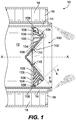
- FIG. 1 a partial view of an exemplary embodiment of a swirler in accordance with the disclosure is shown in Fig. 1 and is designated generally by reference character 100.
- FIGs. 2-5 Other embodiments of swirlers in accordance with the disclosure, or aspects thereof, are provided in Figs. 2-5 , as will be described.
- the systems and methods described herein can be used to facilitate manufacture of swirlers, such as for use as inner air swirlers in fuel injectors and nozzles.
- the swirler 100 is seated as an inner air swirler in the inner air passage 12 of a nozzle 10 that defines a fuel passage 14 outboard of the inner air passage 12 and an outer air passage 16 with an outer air cap 18 outboard of the fuel passage 14.
- Fuel issued from the fuel passage 14 is sheared between swirling air from the outer air swirler 18 and from the inner air swirler 100 to atomize the fuel spray indicated in Fig. 1 by stippling for combustion, e.g., in a combustor of a gas turbine engine.
- Gaseous fuel can be used in addition to or in lieu of liquid fuel.
- the swirler 100 includes an inner body 102 defining a swirl axis A.
- a plurality of swirl vanes 104 extend outward from the inner body 102, i.e.
- the swirl vanes 104 define respective swirl slots 106 therebetween for imparting swirl on a fluid, e.g., air, passing through the swirl slots 106 from upstream of the swirler 100, i.e. the left side of the swirler 100 in Fig. 1 , to downstream of the swirler 100, i.e. on the right side of the swirler 100 in Fig. 1 .
- a fluid e.g., air
- the inner body 102 is a conical body that follows a first cone angle ⁇ which diverges in a downstream direction along the swirl axis A, i.e. the conical body 102 gets further from the swirl axis A the further to the right it is along the swirl axis A in Fig. 1 .
- the swirl vanes 104 define a frustoconical volume, e.g. indicated by the dotted area in Fig. 1 , that follows a second cone angle ⁇ that converges in the downstream direction, i.e. the swirl vanes 104 get closer to the swirl axis A the further to the right they are in Fig. 1 .
- the swirl slots 106 and swirl vanes 104 are oriented tangential to the swirl axis A, in other words, the swirl slots 106 and swirl vanes 104 are not aligned along radii of axis A, but are offset from the radii of axis A as in a radial type swirler.
- An outer ring 108 is connected to the swirl vanes 104 and provides an outward boundary to the swirl slots 106.
- the inner body 102 has a constant wall thickness T, and a plurality of cooling holes 110 therethrough inboard of the swirl slots 106.
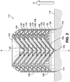
- a method of making swirlers such as swirler 100 described above includes additively manufacturing a vertical, nested stack 112 of swirlers 100.
- Additively manufacturing the vertical stack includes building an external ring 114 and an inner point 116 inside the external ring 114 and additively manufacturing the vertical stack in a vertical build direction D from the external ring 114 and inner point 116.
- the external ring 114 and inner point 116 can be formed on a build plate 118, e.g. of a selective laser sintering machine.
- the inner body 102 of a lower most swirler in the vertical stack 112 originates from the inner point 116.
- the angle of the inner body 102 is conducive to being built up from this central point 116 in additive manufacturing machines.
- the method includes additively manufacturing a central support rod 120 aligned with the swirl axis A of the swirlers 100.
- the central support rod 120 supports between adjacent swirlers 100 in the stack 112 so that the inner bodies 102 of swirlers 100 in the stack 112 can each be built up from a central point, with all the swirlers but the lower most each starting from the central support rod 120 and diverging therefrom in the vertical build direction D.
- the central support rod 120 includes frangible features 122, 124 adjacent each swirler 100 connected thereto.
- Each frangible feature 122 is just below the respective inner body 102 and is a frustoconical indentation in the cylindrical body of the central support rod 120.
- Each frangible feature 124 is a similar frustoconical indentation just above the respective inner body 102.
- the connection 124 between the central support rod 120 and the inner body 102 provides support and allows some heat transfer and mechanical support for a proper build.
- an external tube 126 outboard of the swirl vanes 104 and outer rings 108 of the swirlers is built up from the external ring 114 to support the build from outside.
- a respective ledge 128 protruding inward from the external tube 126 for supporting the build of each of the outer rings 108.
- the frustoconical angle ⁇ of the swirl vanes described above with reference to Fig. 1 is conducive to building up in additive manufacturing machines from the ledges 128.
- FIG. 3 several stacks 112 of swirlers 100 can be fit on a single build plate 118.
- Those skilled in the art will readily appreciate that any suitable number of swirlers in each stack, and any suitable number of stacks can be included on a build plate without departing from the scope of this disclosure.
- each stack 112 can be removed from the build plate 118.
- the external tube 126 labeled in Fig. 2
- the frangible features 122, 124 can then be broken to finish separating the swirlers 100 in the stack 112 from one another. Breaking the frangible features 122, 124 can include twisting the swirlers relative to one another about the swirl axis A.
- any remnant features of the central support rod 120 can be machined away from the swirler 100 using conventional techniques. Having the support structure 132 (labeled in Fig. 4 ) between the frangible feature 122 and the inner body 102 protects the inner body 102, e.g., from being damaged during the additive manufacturing process. It is also contemplated that in addition to or in lieu of using the frangible features 122, 124, the swirlers 100 can be separated from one another by machining away the central support rod 120, e.g., by drilling it down the swirl axis A or using electrical discharge machining (EDM), resulting in swirlers 100 with a central aperture 130 through the inner body 102 thereof. This central aperture 130 can be kept as a cooling bore, or can be plugged, e.g. by welding or brazing.
- EDM electrical discharge machining
- Systems and methods as disclosed herein provide swirlers that can economically be produced using additive manufacturing, while providing design flexibility needed for intricate features such as required in modern engines, e.g. for stringent emissions requirements. Relative to the number of swirlers that can be produced as disclosed herein, there is little support clean up required after a build.
- the conical geometries disclosed herein provide for nearly self-supporting build structures and allow nesting within one another for compact and efficient manufacturing.
Landscapes
- Engineering & Computer Science (AREA)
- Chemical & Material Sciences (AREA)
- Mechanical Engineering (AREA)
- Materials Engineering (AREA)
- Combustion & Propulsion (AREA)
- General Engineering & Computer Science (AREA)
- Manufacturing & Machinery (AREA)
- Physics & Mathematics (AREA)
- Optics & Photonics (AREA)
- Turbine Rotor Nozzle Sealing (AREA)
- Structures Of Non-Positive Displacement Pumps (AREA)
Applications Claiming Priority (1)
| Application Number | Priority Date | Filing Date | Title |
|---|---|---|---|
| US16/248,137 US10557630B1 (en) | 2019-01-15 | 2019-01-15 | Stackable air swirlers |
Publications (2)
| Publication Number | Publication Date |
|---|---|
| EP3683502A1 true EP3683502A1 (de) | 2020-07-22 |
| EP3683502B1 EP3683502B1 (de) | 2022-09-28 |
Family
ID=68610059
Family Applications (1)
| Application Number | Title | Priority Date | Filing Date |
|---|---|---|---|
| EP19209835.8A Active EP3683502B1 (de) | 2019-01-15 | 2019-11-18 | Verfahren zur herstellung von verwirblern |
Country Status (2)
| Country | Link |
|---|---|
| US (2) | US10557630B1 (de) |
| EP (1) | EP3683502B1 (de) |
Citations (5)
| Publication number | Priority date | Publication date | Assignee | Title |
|---|---|---|---|---|
| AU6657181A (en) * | 1981-01-23 | 1982-07-29 | Moskovsky Aviatsionny Institut Imeni Sergo Ordzhonikidze | Rotary burner |
| EP1402956A2 (de) * | 2002-09-30 | 2004-03-31 | Delavan Inc. | Zerstäuber mit diskreten Strahlen |
| EP1605204A2 (de) * | 2004-06-09 | 2005-12-14 | Delavan Inc | Konischer Dallerzeuger für Brennstoffeinspriztdüse und Brennkammersdomen, sowie Verfahren zur Herstellung |
| US20140102572A1 (en) * | 2012-10-17 | 2014-04-17 | Delavan Inc. | Radial vane inner air swirlers |
| US20170205070A1 (en) * | 2016-01-15 | 2017-07-20 | Delavan Inc | Swirlers |
Family Cites Families (54)
| Publication number | Priority date | Publication date | Assignee | Title |
|---|---|---|---|---|
| US2701164A (en) | 1951-04-26 | 1955-02-01 | Gen Motors Corp | Duplex fuel nozzle |
| US3029029A (en) | 1959-05-26 | 1962-04-10 | Parker Hannifin Corp | Dual-orifice return flow nozzle |
| US3638865A (en) | 1970-08-31 | 1972-02-01 | Gen Electric | Fuel spray nozzle |
| US3642210A (en) | 1970-10-05 | 1972-02-15 | Texaco Inc | Oil burner |
| JPS5141693B1 (de) | 1971-05-24 | 1976-11-11 | ||
| US3831854A (en) | 1973-02-23 | 1974-08-27 | Hitachi Ltd | Pressure spray type fuel injection nozzle having air discharge openings |
| US3857156A (en) * | 1973-12-19 | 1974-12-31 | Federal Mogul Corp | Method of making tetrafluoroethylene sealing elements with hydrodynamic action |
| US3980233A (en) | 1974-10-07 | 1976-09-14 | Parker-Hannifin Corporation | Air-atomizing fuel nozzle |
| US4024748A (en) * | 1975-03-11 | 1977-05-24 | Bendo Kogyo Co., Ltd. | Apparatus for producing annular metallic blanks for metallic rings |
| JPS5765879A (en) * | 1980-10-08 | 1982-04-21 | Daido Metal Kogyo Kk | Connecting rod for radial piston motor and manufacturing method thereof |
| US4559009A (en) | 1982-08-06 | 1985-12-17 | Hauck Manufacturing Company | Aggregate dryer burner |
| US4831700A (en) | 1986-07-24 | 1989-05-23 | Ex-Cell-O Corporation | Method for making a fuel injector |
| US4754922A (en) | 1986-07-24 | 1988-07-05 | Ex-Cell-O Corporation | Airblast fuel injector tip with integral cantilever spring fuel metering valve and method for reducing vapor lock from high temperature |
| DE3642122C1 (de) | 1986-12-10 | 1988-06-09 | Mtu Muenchen Gmbh | Brennstoffeinspritzvorrichtung |
| JPH02147610U (de) | 1989-05-11 | 1990-12-14 | ||
| US5499768A (en) | 1989-05-31 | 1996-03-19 | Ohkawara Kakohki Co., Ltd. | Spray nozzle unit |
| US5167116A (en) | 1989-07-07 | 1992-12-01 | Fuel Systems Textron Inc. | Small airblast fuel nozzle with high efficiency inner air swirler |
| US5144804A (en) | 1989-07-07 | 1992-09-08 | Fuel Systems Textron Inc. | Small airblast fuel nozzle with high efficiency inner air swirler |
| US5228624A (en) | 1992-03-02 | 1993-07-20 | Mensink Daniel L | Swirling structure for mixing two concentric fluid flows at nozzle outlet |
| ATE153119T1 (de) | 1992-08-18 | 1997-05-15 | Damper Design Inc | Vorrichtung und verfahren zur zufuhr von teilchenförmigem brennstoff und förderluft |
| US5505045A (en) | 1992-11-09 | 1996-04-09 | Fuel Systems Textron, Inc. | Fuel injector assembly with first and second fuel injectors and inner, outer, and intermediate air discharge chambers |
| US5299909A (en) | 1993-03-25 | 1994-04-05 | Praxair Technology, Inc. | Radial turbine nozzle vane |
| US5605287A (en) | 1995-01-17 | 1997-02-25 | Parker-Hannifin Corporation | Airblast fuel nozzle with swirl slot metering valve |
| US5761907A (en) | 1995-12-11 | 1998-06-09 | Parker-Hannifin Corporation | Thermal gradient dispersing heatshield assembly |
| US5680766A (en) | 1996-01-02 | 1997-10-28 | General Electric Company | Dual fuel mixer for gas turbine combustor |
| US5797268A (en) | 1996-07-05 | 1998-08-25 | Westinghouse Electric Corporation | Partially swirled multi-swirl combustor plate and chimneys |
| DK0836049T3 (da) | 1996-10-08 | 2002-04-08 | Enel Spa | Injektionsdyse til pulveriseret kul |
| US5865024A (en) | 1997-01-14 | 1999-02-02 | General Electric Company | Dual fuel mixer for gas turbine combustor |
| GB9726697D0 (en) | 1997-12-18 | 1998-02-18 | Secr Defence | Fuel injector |
| US6224816B1 (en) | 1998-03-27 | 2001-05-01 | 3D Systems, Inc. | Molding method, apparatus, and device including use of powder metal technology for forming a molding tool with thermal control elements |
| US6082113A (en) | 1998-05-22 | 2000-07-04 | Pratt & Whitney Canada Corp. | Gas turbine fuel injector |
| JP3474774B2 (ja) * | 1998-05-29 | 2003-12-08 | リコーマイクロエレクトロニクス株式会社 | インクジェットヘッドのノズルプレートの製造方法 |
| US6460344B1 (en) | 1999-05-07 | 2002-10-08 | Parker-Hannifin Corporation | Fuel atomization method for turbine combustion engines having aerodynamic turning vanes |
| US6205763B1 (en) | 1999-05-24 | 2001-03-27 | General Electric Company | Method of forming a swirler with as-cast holes |
| US6547163B1 (en) | 1999-10-01 | 2003-04-15 | Parker-Hannifin Corporation | Hybrid atomizing fuel nozzle |
| US6256995B1 (en) | 1999-11-29 | 2001-07-10 | Pratt & Whitney Canada Corp. | Simple low cost fuel nozzle support |
| US6363726B1 (en) | 2000-09-29 | 2002-04-02 | General Electric Company | Mixer having multiple swirlers |
| US6688534B2 (en) | 2001-03-07 | 2004-02-10 | Delavan Inc | Air assist fuel nozzle |
| US6539724B2 (en) | 2001-03-30 | 2003-04-01 | Delavan Inc | Airblast fuel atomization system |
| US6484489B1 (en) | 2001-05-31 | 2002-11-26 | General Electric Company | Method and apparatus for mixing fuel to decrease combustor emissions |
| US6418726B1 (en) | 2001-05-31 | 2002-07-16 | General Electric Company | Method and apparatus for controlling combustor emissions |
| US6755024B1 (en) | 2001-08-23 | 2004-06-29 | Delavan Inc. | Multiplex injector |
| US6698208B2 (en) | 2001-12-14 | 2004-03-02 | Elliott Energy Systems, Inc. | Atomizer for a combustor |
| US6865889B2 (en) | 2002-02-01 | 2005-03-15 | General Electric Company | Method and apparatus to decrease combustor emissions |
| FR2836986B1 (fr) | 2002-03-07 | 2004-11-19 | Snecma Moteurs | Systeme d'injection multi-modes d'un melange air/carburant dans une chambre de combustion |
| US6823677B2 (en) | 2002-09-03 | 2004-11-30 | Pratt & Whitney Canada Corp. | Stress relief feature for aerated gas turbine fuel injector |
| US7251940B2 (en) | 2004-04-30 | 2007-08-07 | United Technologies Corporation | Air assist fuel injector for a combustor |
| US20060064874A1 (en) * | 2004-09-30 | 2006-03-30 | Bonnville Kenneth J | Method of manufacturing a node and of securing a plurality of structural components to the node to form an article |
| US7237730B2 (en) | 2005-03-17 | 2007-07-03 | Pratt & Whitney Canada Corp. | Modular fuel nozzle and method of making |
| US7832102B2 (en) * | 2005-10-06 | 2010-11-16 | Yamashita Rubber Kabushiki Kaisha | Link rod manufacturing method |
| DE102006003259A1 (de) * | 2006-01-19 | 2007-07-26 | Behr Thermot-Tronik Gmbh | Verfahren zum Herstellen von Ventilgehäusen und Ventilgehäuse |
| US9399320B2 (en) * | 2013-03-08 | 2016-07-26 | Stratasys, Inc. | Three-dimensional parts having interconnected hollow patterns, and method for generating and printing thereof |
| US10066082B2 (en) * | 2014-10-16 | 2018-09-04 | Ricoh Company, Ltd. | Three-dimensional object producing method |
| US10245822B2 (en) * | 2015-12-11 | 2019-04-02 | Global Filtration Systems | Method and apparatus for concurrently making multiple three-dimensional objects from multiple solidifiable materials |
-
2019
- 2019-01-15 US US16/248,137 patent/US10557630B1/en active Active
- 2019-11-18 EP EP19209835.8A patent/EP3683502B1/de active Active
-
2020
- 2020-02-10 US US16/785,787 patent/US20200292168A1/en not_active Abandoned
Patent Citations (5)
| Publication number | Priority date | Publication date | Assignee | Title |
|---|---|---|---|---|
| AU6657181A (en) * | 1981-01-23 | 1982-07-29 | Moskovsky Aviatsionny Institut Imeni Sergo Ordzhonikidze | Rotary burner |
| EP1402956A2 (de) * | 2002-09-30 | 2004-03-31 | Delavan Inc. | Zerstäuber mit diskreten Strahlen |
| EP1605204A2 (de) * | 2004-06-09 | 2005-12-14 | Delavan Inc | Konischer Dallerzeuger für Brennstoffeinspriztdüse und Brennkammersdomen, sowie Verfahren zur Herstellung |
| US20140102572A1 (en) * | 2012-10-17 | 2014-04-17 | Delavan Inc. | Radial vane inner air swirlers |
| US20170205070A1 (en) * | 2016-01-15 | 2017-07-20 | Delavan Inc | Swirlers |
Also Published As
| Publication number | Publication date |
|---|---|
| US20200292168A1 (en) | 2020-09-17 |
| US10557630B1 (en) | 2020-02-11 |
| EP3683502B1 (de) | 2022-09-28 |
Similar Documents
| Publication | Publication Date | Title |
|---|---|---|
| US12055295B2 (en) | Fuel nozzle structure for air assist injection | |
| US7707832B2 (en) | Device for injecting a mixture of air and fuel, and a combustion chamber and turbomachine provided with such a device | |
| EP1605204B1 (de) | Verfahren zur Herstellung konischer Drallerzeuger für Brennstoffeinspriztdüse | |
| EP3671039B1 (de) | Mehrpunktkraftstoffeinspritzsystem mit hitzeschild | |
| US7862295B2 (en) | Device for guiding a stream of air entering a combustion chamber of a turbomachine | |
| JP5110635B2 (ja) | 空気と燃料の混合物を噴射する装置、ならびにそのような装置が設けられた燃焼室とターボ機械 | |
| US11015811B2 (en) | Plate swirler with converging swirl passages | |
| EP3336432B1 (de) | Gestufter radialer luftwirbler mit radialem flüssigkraftstoffverteiler | |
| US10739006B2 (en) | Fuel nozzle for a gas turbine engine | |
| US11168886B2 (en) | Injector nose for turbomachine including a secondary fuel swirler with changing section | |
| CN113503564B (zh) | 用于在涡轮发动机中使用的燃烧器 | |
| EP3683502B1 (de) | Verfahren zur herstellung von verwirblern | |
| EP4403829B1 (de) | Brennstoffdüsen | |
| US4821387A (en) | Method of manufacturing cooling film devices for combustion chambers of turbomachines | |
| US11774097B2 (en) | Thermal resistant air cap | |
| EP4212782B1 (de) | Fluidverteiler mit kanälen für gasturbinenbrennstoffinjector und herstellungsverfahren | |
| CN211502776U (zh) | 一种槽环形复合割嘴 |
Legal Events
| Date | Code | Title | Description |
|---|---|---|---|
| PUAI | Public reference made under article 153(3) epc to a published international application that has entered the european phase |
Free format text: ORIGINAL CODE: 0009012 |
|
| STAA | Information on the status of an ep patent application or granted ep patent |
Free format text: STATUS: THE APPLICATION HAS BEEN PUBLISHED |
|
| AK | Designated contracting states |
Kind code of ref document: A1 Designated state(s): AL AT BE BG CH CY CZ DE DK EE ES FI FR GB GR HR HU IE IS IT LI LT LU LV MC MK MT NL NO PL PT RO RS SE SI SK SM TR |
|
| AX | Request for extension of the european patent |
Extension state: BA ME |
|
| STAA | Information on the status of an ep patent application or granted ep patent |
Free format text: STATUS: REQUEST FOR EXAMINATION WAS MADE |
|
| 17P | Request for examination filed |
Effective date: 20210119 |
|
| RBV | Designated contracting states (corrected) |
Designated state(s): AL AT BE BG CH CY CZ DE DK EE ES FI FR GB GR HR HU IE IS IT LI LT LU LV MC MK MT NL NO PL PT RO RS SE SI SK SM TR |
|
| GRAP | Despatch of communication of intention to grant a patent |
Free format text: ORIGINAL CODE: EPIDOSNIGR1 |
|
| STAA | Information on the status of an ep patent application or granted ep patent |
Free format text: STATUS: GRANT OF PATENT IS INTENDED |
|
| INTG | Intention to grant announced |
Effective date: 20220407 |
|
| RIN1 | Information on inventor provided before grant (corrected) |
Inventor name: TIBBS, ANDY W. Inventor name: GREENFIELD, JACOB Inventor name: SAMO, JOSEPH Inventor name: RYON, JASON A. |
|
| RAP3 | Party data changed (applicant data changed or rights of an application transferred) |
Owner name: COLLINS ENGINE NOZZLES, INC. |
|
| GRAS | Grant fee paid |
Free format text: ORIGINAL CODE: EPIDOSNIGR3 |
|
| GRAA | (expected) grant |
Free format text: ORIGINAL CODE: 0009210 |
|
| STAA | Information on the status of an ep patent application or granted ep patent |
Free format text: STATUS: THE PATENT HAS BEEN GRANTED |
|
| AK | Designated contracting states |
Kind code of ref document: B1 Designated state(s): AL AT BE BG CH CY CZ DE DK EE ES FI FR GB GR HR HU IE IS IT LI LT LU LV MC MK MT NL NO PL PT RO RS SE SI SK SM TR |
|
| REG | Reference to a national code |
Ref country code: GB Ref legal event code: FG4D |
|
| REG | Reference to a national code |
Ref country code: CH Ref legal event code: EP |
|
| REG | Reference to a national code |
Ref country code: AT Ref legal event code: REF Ref document number: 1521464 Country of ref document: AT Kind code of ref document: T Effective date: 20221015 |
|
| REG | Reference to a national code |
Ref country code: DE Ref legal event code: R096 Ref document number: 602019019986 Country of ref document: DE |
|
| REG | Reference to a national code |
Ref country code: IE Ref legal event code: FG4D |
|
| REG | Reference to a national code |
Ref country code: LT Ref legal event code: MG9D |
|
| PG25 | Lapsed in a contracting state [announced via postgrant information from national office to epo] |
Ref country code: SE Free format text: LAPSE BECAUSE OF FAILURE TO SUBMIT A TRANSLATION OF THE DESCRIPTION OR TO PAY THE FEE WITHIN THE PRESCRIBED TIME-LIMIT Effective date: 20220928 Ref country code: RS Free format text: LAPSE BECAUSE OF FAILURE TO SUBMIT A TRANSLATION OF THE DESCRIPTION OR TO PAY THE FEE WITHIN THE PRESCRIBED TIME-LIMIT Effective date: 20220928 Ref country code: NO Free format text: LAPSE BECAUSE OF FAILURE TO SUBMIT A TRANSLATION OF THE DESCRIPTION OR TO PAY THE FEE WITHIN THE PRESCRIBED TIME-LIMIT Effective date: 20221228 Ref country code: LV Free format text: LAPSE BECAUSE OF FAILURE TO SUBMIT A TRANSLATION OF THE DESCRIPTION OR TO PAY THE FEE WITHIN THE PRESCRIBED TIME-LIMIT Effective date: 20220928 Ref country code: LT Free format text: LAPSE BECAUSE OF FAILURE TO SUBMIT A TRANSLATION OF THE DESCRIPTION OR TO PAY THE FEE WITHIN THE PRESCRIBED TIME-LIMIT Effective date: 20220928 Ref country code: FI Free format text: LAPSE BECAUSE OF FAILURE TO SUBMIT A TRANSLATION OF THE DESCRIPTION OR TO PAY THE FEE WITHIN THE PRESCRIBED TIME-LIMIT Effective date: 20220928 |
|
| REG | Reference to a national code |
Ref country code: NL Ref legal event code: MP Effective date: 20220928 |
|
| REG | Reference to a national code |
Ref country code: AT Ref legal event code: MK05 Ref document number: 1521464 Country of ref document: AT Kind code of ref document: T Effective date: 20220928 |
|
| PG25 | Lapsed in a contracting state [announced via postgrant information from national office to epo] |
Ref country code: HR Free format text: LAPSE BECAUSE OF FAILURE TO SUBMIT A TRANSLATION OF THE DESCRIPTION OR TO PAY THE FEE WITHIN THE PRESCRIBED TIME-LIMIT Effective date: 20220928 Ref country code: GR Free format text: LAPSE BECAUSE OF FAILURE TO SUBMIT A TRANSLATION OF THE DESCRIPTION OR TO PAY THE FEE WITHIN THE PRESCRIBED TIME-LIMIT Effective date: 20221229 |
|
| PG25 | Lapsed in a contracting state [announced via postgrant information from national office to epo] |
Ref country code: SM Free format text: LAPSE BECAUSE OF FAILURE TO SUBMIT A TRANSLATION OF THE DESCRIPTION OR TO PAY THE FEE WITHIN THE PRESCRIBED TIME-LIMIT Effective date: 20220928 Ref country code: RO Free format text: LAPSE BECAUSE OF FAILURE TO SUBMIT A TRANSLATION OF THE DESCRIPTION OR TO PAY THE FEE WITHIN THE PRESCRIBED TIME-LIMIT Effective date: 20220928 Ref country code: PT Free format text: LAPSE BECAUSE OF FAILURE TO SUBMIT A TRANSLATION OF THE DESCRIPTION OR TO PAY THE FEE WITHIN THE PRESCRIBED TIME-LIMIT Effective date: 20230130 Ref country code: ES Free format text: LAPSE BECAUSE OF FAILURE TO SUBMIT A TRANSLATION OF THE DESCRIPTION OR TO PAY THE FEE WITHIN THE PRESCRIBED TIME-LIMIT Effective date: 20220928 Ref country code: CZ Free format text: LAPSE BECAUSE OF FAILURE TO SUBMIT A TRANSLATION OF THE DESCRIPTION OR TO PAY THE FEE WITHIN THE PRESCRIBED TIME-LIMIT Effective date: 20220928 Ref country code: AT Free format text: LAPSE BECAUSE OF FAILURE TO SUBMIT A TRANSLATION OF THE DESCRIPTION OR TO PAY THE FEE WITHIN THE PRESCRIBED TIME-LIMIT Effective date: 20220928 |
|
| PG25 | Lapsed in a contracting state [announced via postgrant information from national office to epo] |
Ref country code: SK Free format text: LAPSE BECAUSE OF FAILURE TO SUBMIT A TRANSLATION OF THE DESCRIPTION OR TO PAY THE FEE WITHIN THE PRESCRIBED TIME-LIMIT Effective date: 20220928 Ref country code: PL Free format text: LAPSE BECAUSE OF FAILURE TO SUBMIT A TRANSLATION OF THE DESCRIPTION OR TO PAY THE FEE WITHIN THE PRESCRIBED TIME-LIMIT Effective date: 20220928 Ref country code: IS Free format text: LAPSE BECAUSE OF FAILURE TO SUBMIT A TRANSLATION OF THE DESCRIPTION OR TO PAY THE FEE WITHIN THE PRESCRIBED TIME-LIMIT Effective date: 20230128 Ref country code: EE Free format text: LAPSE BECAUSE OF FAILURE TO SUBMIT A TRANSLATION OF THE DESCRIPTION OR TO PAY THE FEE WITHIN THE PRESCRIBED TIME-LIMIT Effective date: 20220928 |
|
| REG | Reference to a national code |
Ref country code: DE Ref legal event code: R097 Ref document number: 602019019986 Country of ref document: DE |
|
| PG25 | Lapsed in a contracting state [announced via postgrant information from national office to epo] |
Ref country code: NL Free format text: LAPSE BECAUSE OF FAILURE TO SUBMIT A TRANSLATION OF THE DESCRIPTION OR TO PAY THE FEE WITHIN THE PRESCRIBED TIME-LIMIT Effective date: 20220928 Ref country code: MC Free format text: LAPSE BECAUSE OF FAILURE TO SUBMIT A TRANSLATION OF THE DESCRIPTION OR TO PAY THE FEE WITHIN THE PRESCRIBED TIME-LIMIT Effective date: 20220928 Ref country code: AL Free format text: LAPSE BECAUSE OF FAILURE TO SUBMIT A TRANSLATION OF THE DESCRIPTION OR TO PAY THE FEE WITHIN THE PRESCRIBED TIME-LIMIT Effective date: 20220928 |
|
| REG | Reference to a national code |
Ref country code: CH Ref legal event code: PL |
|
| P01 | Opt-out of the competence of the unified patent court (upc) registered |
Effective date: 20230530 |
|
| REG | Reference to a national code |
Ref country code: BE Ref legal event code: MM Effective date: 20221130 |
|
| PG25 | Lapsed in a contracting state [announced via postgrant information from national office to epo] |
Ref country code: LI Free format text: LAPSE BECAUSE OF NON-PAYMENT OF DUE FEES Effective date: 20221130 Ref country code: DK Free format text: LAPSE BECAUSE OF FAILURE TO SUBMIT A TRANSLATION OF THE DESCRIPTION OR TO PAY THE FEE WITHIN THE PRESCRIBED TIME-LIMIT Effective date: 20220928 Ref country code: CH Free format text: LAPSE BECAUSE OF NON-PAYMENT OF DUE FEES Effective date: 20221130 |
|
| PLBE | No opposition filed within time limit |
Free format text: ORIGINAL CODE: 0009261 |
|
| STAA | Information on the status of an ep patent application or granted ep patent |
Free format text: STATUS: NO OPPOSITION FILED WITHIN TIME LIMIT |
|
| PG25 | Lapsed in a contracting state [announced via postgrant information from national office to epo] |
Ref country code: LU Free format text: LAPSE BECAUSE OF NON-PAYMENT OF DUE FEES Effective date: 20221118 |
|
| 26N | No opposition filed |
Effective date: 20230629 |
|
| PG25 | Lapsed in a contracting state [announced via postgrant information from national office to epo] |
Ref country code: IE Free format text: LAPSE BECAUSE OF NON-PAYMENT OF DUE FEES Effective date: 20221118 |
|
| PG25 | Lapsed in a contracting state [announced via postgrant information from national office to epo] |
Ref country code: SI Free format text: LAPSE BECAUSE OF FAILURE TO SUBMIT A TRANSLATION OF THE DESCRIPTION OR TO PAY THE FEE WITHIN THE PRESCRIBED TIME-LIMIT Effective date: 20220928 Ref country code: BE Free format text: LAPSE BECAUSE OF NON-PAYMENT OF DUE FEES Effective date: 20221130 |
|
| PG25 | Lapsed in a contracting state [announced via postgrant information from national office to epo] |
Ref country code: HU Free format text: LAPSE BECAUSE OF FAILURE TO SUBMIT A TRANSLATION OF THE DESCRIPTION OR TO PAY THE FEE WITHIN THE PRESCRIBED TIME-LIMIT; INVALID AB INITIO Effective date: 20191118 |
|
| PG25 | Lapsed in a contracting state [announced via postgrant information from national office to epo] |
Ref country code: CY Free format text: LAPSE BECAUSE OF FAILURE TO SUBMIT A TRANSLATION OF THE DESCRIPTION OR TO PAY THE FEE WITHIN THE PRESCRIBED TIME-LIMIT Effective date: 20220928 |
|
| PG25 | Lapsed in a contracting state [announced via postgrant information from national office to epo] |
Ref country code: MK Free format text: LAPSE BECAUSE OF FAILURE TO SUBMIT A TRANSLATION OF THE DESCRIPTION OR TO PAY THE FEE WITHIN THE PRESCRIBED TIME-LIMIT Effective date: 20220928 Ref country code: IT Free format text: LAPSE BECAUSE OF FAILURE TO SUBMIT A TRANSLATION OF THE DESCRIPTION OR TO PAY THE FEE WITHIN THE PRESCRIBED TIME-LIMIT Effective date: 20220928 |
|
| PG25 | Lapsed in a contracting state [announced via postgrant information from national office to epo] |
Ref country code: TR Free format text: LAPSE BECAUSE OF FAILURE TO SUBMIT A TRANSLATION OF THE DESCRIPTION OR TO PAY THE FEE WITHIN THE PRESCRIBED TIME-LIMIT Effective date: 20220928 |
|
| PG25 | Lapsed in a contracting state [announced via postgrant information from national office to epo] |
Ref country code: BG Free format text: LAPSE BECAUSE OF FAILURE TO SUBMIT A TRANSLATION OF THE DESCRIPTION OR TO PAY THE FEE WITHIN THE PRESCRIBED TIME-LIMIT Effective date: 20220928 |
|
| PG25 | Lapsed in a contracting state [announced via postgrant information from national office to epo] |
Ref country code: MT Free format text: LAPSE BECAUSE OF FAILURE TO SUBMIT A TRANSLATION OF THE DESCRIPTION OR TO PAY THE FEE WITHIN THE PRESCRIBED TIME-LIMIT Effective date: 20220928 |
|
| PGFP | Annual fee paid to national office [announced via postgrant information from national office to epo] |
Ref country code: DE Payment date: 20251022 Year of fee payment: 7 |
|
| PGFP | Annual fee paid to national office [announced via postgrant information from national office to epo] |
Ref country code: GB Payment date: 20251022 Year of fee payment: 7 |
|
| PGFP | Annual fee paid to national office [announced via postgrant information from national office to epo] |
Ref country code: FR Payment date: 20251022 Year of fee payment: 7 |