EP3683531A1 - Kreuzstromwärmetauscher - Google Patents
Kreuzstromwärmetauscher Download PDFInfo
- Publication number
- EP3683531A1 EP3683531A1 EP20151748.9A EP20151748A EP3683531A1 EP 3683531 A1 EP3683531 A1 EP 3683531A1 EP 20151748 A EP20151748 A EP 20151748A EP 3683531 A1 EP3683531 A1 EP 3683531A1
- Authority
- EP
- European Patent Office
- Prior art keywords
- tubes
- flow
- heat exchanger
- fluid
- ducts
- Prior art date
- Legal status (The legal status is an assumption and is not a legal conclusion. Google has not performed a legal analysis and makes no representation as to the accuracy of the status listed.)
- Granted
Links
Images



Classifications
-
- F—MECHANICAL ENGINEERING; LIGHTING; HEATING; WEAPONS; BLASTING
- F28—HEAT EXCHANGE IN GENERAL
- F28D—HEAT-EXCHANGE APPARATUS, NOT PROVIDED FOR IN ANOTHER SUBCLASS, IN WHICH THE HEAT-EXCHANGE MEDIA DO NOT COME INTO DIRECT CONTACT
- F28D7/00—Heat-exchange apparatus having stationary tubular conduit assemblies for both heat-exchange media, the media being in contact with different sides of a conduit wall
- F28D7/005—Heat-exchange apparatus having stationary tubular conduit assemblies for both heat-exchange media, the media being in contact with different sides of a conduit wall the conduits for only one medium being tubes having bent portions or being assembled from bent tubes or being tubes having a toroidal configuration
-
- F—MECHANICAL ENGINEERING; LIGHTING; HEATING; WEAPONS; BLASTING
- F28—HEAT EXCHANGE IN GENERAL
- F28D—HEAT-EXCHANGE APPARATUS, NOT PROVIDED FOR IN ANOTHER SUBCLASS, IN WHICH THE HEAT-EXCHANGE MEDIA DO NOT COME INTO DIRECT CONTACT
- F28D1/00—Heat-exchange apparatus having stationary conduit assemblies for one heat-exchange medium only, the media being in contact with different sides of the conduit wall, in which the other heat-exchange medium is a large body of fluid, e.g. domestic or motor car radiators
- F28D1/02—Heat-exchange apparatus having stationary conduit assemblies for one heat-exchange medium only, the media being in contact with different sides of the conduit wall, in which the other heat-exchange medium is a large body of fluid, e.g. domestic or motor car radiators with heat-exchange conduits immersed in the body of fluid
- F28D1/04—Heat-exchange apparatus having stationary conduit assemblies for one heat-exchange medium only, the media being in contact with different sides of the conduit wall, in which the other heat-exchange medium is a large body of fluid, e.g. domestic or motor car radiators with heat-exchange conduits immersed in the body of fluid with tubular conduits
- F28D1/047—Heat-exchange apparatus having stationary conduit assemblies for one heat-exchange medium only, the media being in contact with different sides of the conduit wall, in which the other heat-exchange medium is a large body of fluid, e.g. domestic or motor car radiators with heat-exchange conduits immersed in the body of fluid with tubular conduits the conduits being bent, e.g. in a serpentine or zig-zag
-
- F—MECHANICAL ENGINEERING; LIGHTING; HEATING; WEAPONS; BLASTING
- F28—HEAT EXCHANGE IN GENERAL
- F28D—HEAT-EXCHANGE APPARATUS, NOT PROVIDED FOR IN ANOTHER SUBCLASS, IN WHICH THE HEAT-EXCHANGE MEDIA DO NOT COME INTO DIRECT CONTACT
- F28D1/00—Heat-exchange apparatus having stationary conduit assemblies for one heat-exchange medium only, the media being in contact with different sides of the conduit wall, in which the other heat-exchange medium is a large body of fluid, e.g. domestic or motor car radiators
- F28D1/02—Heat-exchange apparatus having stationary conduit assemblies for one heat-exchange medium only, the media being in contact with different sides of the conduit wall, in which the other heat-exchange medium is a large body of fluid, e.g. domestic or motor car radiators with heat-exchange conduits immersed in the body of fluid
- F28D1/04—Heat-exchange apparatus having stationary conduit assemblies for one heat-exchange medium only, the media being in contact with different sides of the conduit wall, in which the other heat-exchange medium is a large body of fluid, e.g. domestic or motor car radiators with heat-exchange conduits immersed in the body of fluid with tubular conduits
- F28D1/047—Heat-exchange apparatus having stationary conduit assemblies for one heat-exchange medium only, the media being in contact with different sides of the conduit wall, in which the other heat-exchange medium is a large body of fluid, e.g. domestic or motor car radiators with heat-exchange conduits immersed in the body of fluid with tubular conduits the conduits being bent, e.g. in a serpentine or zig-zag
- F28D1/0477—Heat-exchange apparatus having stationary conduit assemblies for one heat-exchange medium only, the media being in contact with different sides of the conduit wall, in which the other heat-exchange medium is a large body of fluid, e.g. domestic or motor car radiators with heat-exchange conduits immersed in the body of fluid with tubular conduits the conduits being bent, e.g. in a serpentine or zig-zag the conduits being bent in a serpentine or zig-zag
-
- F—MECHANICAL ENGINEERING; LIGHTING; HEATING; WEAPONS; BLASTING
- F28—HEAT EXCHANGE IN GENERAL
- F28D—HEAT-EXCHANGE APPARATUS, NOT PROVIDED FOR IN ANOTHER SUBCLASS, IN WHICH THE HEAT-EXCHANGE MEDIA DO NOT COME INTO DIRECT CONTACT
- F28D7/00—Heat-exchange apparatus having stationary tubular conduit assemblies for both heat-exchange media, the media being in contact with different sides of a conduit wall
- F28D7/08—Heat-exchange apparatus having stationary tubular conduit assemblies for both heat-exchange media, the media being in contact with different sides of a conduit wall the conduits being otherwise bent, e.g. in a serpentine or zig-zag
-
- F—MECHANICAL ENGINEERING; LIGHTING; HEATING; WEAPONS; BLASTING
- F28—HEAT EXCHANGE IN GENERAL
- F28D—HEAT-EXCHANGE APPARATUS, NOT PROVIDED FOR IN ANOTHER SUBCLASS, IN WHICH THE HEAT-EXCHANGE MEDIA DO NOT COME INTO DIRECT CONTACT
- F28D7/00—Heat-exchange apparatus having stationary tubular conduit assemblies for both heat-exchange media, the media being in contact with different sides of a conduit wall
- F28D7/08—Heat-exchange apparatus having stationary tubular conduit assemblies for both heat-exchange media, the media being in contact with different sides of a conduit wall the conduits being otherwise bent, e.g. in a serpentine or zig-zag
- F28D7/082—Heat-exchange apparatus having stationary tubular conduit assemblies for both heat-exchange media, the media being in contact with different sides of a conduit wall the conduits being otherwise bent, e.g. in a serpentine or zig-zag with serpentine or zig-zag configuration
-
- F—MECHANICAL ENGINEERING; LIGHTING; HEATING; WEAPONS; BLASTING
- F28—HEAT EXCHANGE IN GENERAL
- F28D—HEAT-EXCHANGE APPARATUS, NOT PROVIDED FOR IN ANOTHER SUBCLASS, IN WHICH THE HEAT-EXCHANGE MEDIA DO NOT COME INTO DIRECT CONTACT
- F28D7/00—Heat-exchange apparatus having stationary tubular conduit assemblies for both heat-exchange media, the media being in contact with different sides of a conduit wall
- F28D7/16—Heat-exchange apparatus having stationary tubular conduit assemblies for both heat-exchange media, the media being in contact with different sides of a conduit wall the conduits being arranged in parallel spaced relation
-
- F—MECHANICAL ENGINEERING; LIGHTING; HEATING; WEAPONS; BLASTING
- F28—HEAT EXCHANGE IN GENERAL
- F28F—DETAILS OF HEAT-EXCHANGE AND HEAT-TRANSFER APPARATUS, OF GENERAL APPLICATION
- F28F1/00—Tubular elements; Assemblies of tubular elements
- F28F1/08—Tubular elements crimped or corrugated in longitudinal section
-
- F—MECHANICAL ENGINEERING; LIGHTING; HEATING; WEAPONS; BLASTING
- F28—HEAT EXCHANGE IN GENERAL
- F28F—DETAILS OF HEAT-EXCHANGE AND HEAT-TRANSFER APPARATUS, OF GENERAL APPLICATION
- F28F2250/00—Arrangements for modifying the flow of the heat exchange media, e.g. flow guiding means; Particular flow patterns
- F28F2250/10—Particular pattern of flow of the heat exchange media
- F28F2250/106—Particular pattern of flow of the heat exchange media with cross flow
Definitions
- the present invention relates to heat exchangers and, in particular, to a heat exchanger that utilizes a cross-flow configuration to increase the thermal energy transfer primary surface area of the heat exchanger.
- Heat exchangers aim to transfer heat between a hot fluid and a cool fluid.
- walls primary surfaces
- fins secondary surfaces
- the heat transfer through primary surface is very good because the walls are thin and the distance the thermal energy needs to travel is relatively small.
- the heat transfer through secondary surfaces is less efficient than primary surfaces because the thermal energy must travel a longer distance along the length of the fins.
- the most compact heat exchangers i.e., high surface area per unit volume
- a heat exchanger including a plurality of tubes, a header, and a plurality of flow voids.
- the plurality of tubes extends in a first direction through which a first fluid is configured to flow.
- Each of the plurality of tubes have waves that repeat at regular intervals along the first flow direction and are spaced from one another vertically and laterally in the second direction.
- the header extends in the first direction and is attached to each of the plurality of tubes.
- the header is configured to convey the first fluid to each of the plurality of tubes.
- the plurality of flow voids are formed between the plurality of tubes.
- the plurality of flow voids extend in a second direction through which a second fluid is configured to flow such that the second fluid is in thermal contact with the plurality of tubes.
- a heat exchanger includes multiple ducts extending substantially in a first direction and configured to accommodate the flow of a first fluid with each duct of the multiple ducts having a wave pattern and a cross-flow zone extending substantially in a second direction perpendicular to the first direction with the multiple ducts extending through the cross-flow zone.
- the cross-flow zone is configured to accommodate the flow of a second fluid such that the second fluid is in contact with the multiple ducts.
- a heat exchanger is disclosed herein that utilizes a cross-flow configuration to transfer thermal energy between a first fluid and a second fluid.
- the cross-flow configuration includes multiple tubes/ducts (hereinafter referred to as "tubes”) that extend in a first direction and are surrounded by and extend through a plurality of flow voids, which are shown as the voids formed between the plurality of tubes (hereinafter referred to as a singular "flow void").
- the first fluid flows through the tubes, and the second fluid flows through the flow void substantially in a second direction, which is perpendicular to the first direction and the tubes.
- Such a configuration results in almost the entire surface area of the tubes being primary surface area, thereby increasing the thermal energy transfer between the first fluid and the second fluid.
- the tubes can have a wave pattern that increases the surface area of the tubes within the flow void by increasing the length of the tubes.
- the waves can have a variety of shapes, including waves that are based on a sinusoidal (i.e., cosine or sine) curve.
- the tubes can be a variety of shapes, including tubes that each have a circular cross-sectional shape or an oblong cross-sectional shape (for example, oval, ellipsoidal, or any other oblong shape), to increase or decrease the flow area of the tubes and/or the primary surface area of the tubes. Changes to the cross-sectional shape will also impact the pressure drop of the flow in the second direction. Oblong cross-sectional shapes will have lower second direction pressure drop compared to round cross sectional shapes.
- the heat exchanger can include a plurality of walls that extend between laterally adjacent tubes such that the plurality of walls divide the flow void into multiple discrete flow channels through which the second fluid can flow.
- the walls can be any thickness and include features for additional thermal energy transfer capabilities, such as fins or other structures. It should be noted that the walls are barriers separating the flow void into flow channels and are not fins that extend into the flow void merely to increase the thermal energy transfer surface area of the heat exchanger.
- the flow void being divided into discrete flow channels provides a heat exchanger that experiences channel flow characteristics in both flow directions, which may be advantageous in some applications. Further, the walls provide additional surface area through which thermal energy can transfer between the first fluid and the second fluid, thereby increasing the thermal energy transfer between the first fluid and the second fluid without the addition of volume to the flow void and heat exchanger.
- Additive manufacturing can be utilized to create the disclosed heat exchanger so that all components of the heat exchanger are formed during one manufacturing process to form a continuous and monolithic structure. Further, additive manufacturing can easily and reliably form the heat exchanger with complex tubes, walls, and/or shapes and small tolerances.
- continuous and monolithic means formed as a single unit without seams, weld lines, adhesive lines, or any other discontinuities.
- the waves of the tubes (which, for example, are based on sinusoidal curves) can have alternate amplitudes, wavelengths, and other characteristics as required for optimal thermal energy transfer and to accommodate a designed flow of the first fluid and/or second fluid. Further, the waves can have a variety of shapes, such as triangular waves with pointed peaks and troughs, rectangular waves with flat tops and bottoms, and/or other configurations.
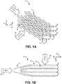
- FIG. 1A is a perspective view of a first embodiment of a heat exchanger
- FIG. 1B is a top view of the heat exchanger in FIG. 1A
- FIG. 1C is an elevation view of the heat exchanger in FIG. 1A
- FIG. 1D is a front view of the heat exchanger in FIG. 1A
- Heat exchanger 10 includes tubes 12 arranged into first column 14, second column 16, third column 18, and fourth column 20 as well as first row 22, second row 24, and third row 26.
- Heat exchanger 10 also includes header 27 attached to tubes 12 and flow void 28 through which tubes 12 extend.
- First fluid 30 is configured to flow through header 27 and tubes 12 in first direction 32
- second fluid 34 is configured to flow through flow void 28 in second direction 36. While not shown, flow void 28 can be bounded on all sides by walls (with openings to allow the flow of second fluid 34) to enclose heat exchanger 10.
- Tubes 12 extend laterally in first direction 32 through flow void 28. Tubes 12 provide a number of enclosed ducts through which first fluid 30 is configured to flow. First fluid 30 within tubes 12 either accepts thermal energy from second fluid 34 or conveys thermal energy to second fluid 34 depending on which of first fluid 30 and second fluid 34 has a greater temperature. In this disclosure, first fluid 30 has a greater temperature than second fluid 34, but in other embodiments second fluid 34 can have a greater temperature than first fluid 30. While flowing through tubes 12, thermal energy flows through the walls comprising tubes 12 and into second fluid 34 within flow void 28.
- the amount of thermal energy transferred depends on a variety of factors and can be adjusted by modifying the flow velocity of first fluid 30 and/or second fluid 34, the thickness of the walls of tubes 12, the size, shape, and surface area of tubes 12, and other factors. These factors can be adjusted and/or selected depending on the thermal energy transfer needs of heat exchanger 10.
- tubes 12 can vary depending on the size, shape, and thermal energy transfer needs (among other considerations) of heat exchanger 10. As shown in FIGS. 1A-1D , tubes 12 are arranged in four columns horizontally adjacent to one another (first column 14, second column 16, third column 18, and fourth column 20) each having three tubes 12 (thus, there are three rows: first row 22, second row 24, and third row 26). Tubes 12 in each of the columns 14-20 are horizontally aligned to be directly above and below adjacent tubes, but other embodiments can have tubes 12 in other arrangement. The configuration of tubes 12 being horizontally aligned is seen most easily in FIG. 1B , which shows the four column 14-20 horizontally aligned.
- Tubes 12 are arranged in three rows 22-26 that are vertically offset from adjacent tubes in the same row to form a zig-zag pattern. Tubes 12 in the three rows 22-26 being vertically offset is seen most easily in FIG. 1C , which shows tubes 12 in each of the three rows 22-26 having two vertical positions.
- the configuration in which adjacent tubes in rows 22-26 are vertically offset ensures that second fluid 34 flowing through flow void 28 contacts the entire surface of each tube 12 to provide maximum thermal energy transfer. Further, the distance/space between tubes 12 can be as small or large as necessary to meet the thermal energy transfer needs of heat exchanger 10.
- Each of tubes 12 can have a wave pattern based on a sinusoidal curve.
- Each of tubes 12 can be configured such that all peaks and troughs line up or are offset from one another (e.g., the waves of adjacent tubes 12 can be offset from one another by one-half wavelength)
- each of tubes 12 can have waves with different wavelengths, amplitudes, and shapes, such as waves that are triangular (i.e., pointed peaks and troughs), rectangular (i.e., flat peaks and troughs), or another configuration. While the disclosed embodiments show tubes 12 with waves that propagate vertically, the waves can be configured to propagate laterally or in other directions.
- Tubes 12 can have any cross-sectional shape, such as circular, oblong, or rectangular. Further, adjacent tubes 12 can have different cross-sectional shapes than one another.
- Header 27 is upstream from and conveys first fluid 30 to each tube 12. Header 27 extends substantially in first direction 32 and is attached to each tube 12. Header 27 can have a variety of configurations including having one or multiple inlets that accept first fluid 30 and divide first fluid 30 to flow into tubes 12. Header 27 can be continuous and monolithic with tubes 12 or can be a separate component fastened to each of tubes 12. Additionally, while not shown, heat exchanger 10 can include a similar header on a downstream end of tubes 12 to merge first fluid 30 into one or multiple consolidated flow paths.
- Tubes 12 extend across flow void 28.
- Second fluid 34 is configured to flow through flow void 28 in second direction 36 to contact tubes 12 to transfer thermal energy between first fluid 30 within tubes 12 and second fluid 34 within flow void 28.
- Flow void 28 can be enclosed by walls (not shown) or another structure and allows second fluid 34 to flow freely (whether turbulent or laminar) around tubes 12. While the disclosed embodiments discuss second fluid 34 flowing through flow void 28, other embodiments can include a configuration in which second fluid 34 is merely contained within flow void 28 and does not flow but rather accepts or gives thermal energy to first fluid 28 within tubes 12 without flowing through flow void 28. As shown in FIG.
- second fluid 34 flowing through flow void 28 can, after contacting one tube 12, be directed upwards so as to flow over tube 12 or downwards so as to flow under tube 12 to provide increased thermal energy transfer because second fluid 34 is able to flow completely around tubes 12 to contact the entire primary thermal energy transfer surface area of tubes 12.
- Other embodiments can include columns 14-20 that are not aligned such that second flow 34 is not directly upwards and downwards as shown in FIG. 1D .
- flow void 28 can include substantially lateral walls between adjacent tubes 12 to divide the flow of second fluid 34 into discrete channels.
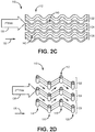
- FIG. 2A is a perspective view of a second embodiment of a heat exchanger
- FIG. 2B is a top view of the heat exchanger in FIG. 2A
- FIG. 2C is an elevation view of the heat exchanger in FIG. 2A
- FIG. 2D is a front view of the heat exchanger in FIG. 2A
- Heat exchanger 110 includes tubes 112 comprising first column 114, second column 116, third column 118, and fourth column 120 as well as first row 122, second row 124, and third row 126.
- Heat exchanger 110 also includes flow void 128, first fluid 130, first direction 132, second fluid 134, and second direction 136.
- the components of heat exchanger 110 are the same as those similarly named with regards to heat exchanger 10 in FIGS.
- heat exchanger 110 includes walls 138 that extend substantially laterally between adjacent tubes 112 to divide flow void 128 into multiple discrete flow channels 140 and 142. Additionally, while not shown, heat exchanger 110 can be configured to include a header similar to header 27 of heat exchanger 10.
- walls 138 extend substantially laterally between and connect to tubes 12 of each of first row 122, second row 124, and third row 126 (i.e., walls 138 extend between horizontally adjacent tubes 112).
- walls 138 extend between adjacent tubes 112 of first row 122 in a zig-zag pattern (because adjacent tubes 112 in each row 122-126 are offset from one another).
- a similar configuration is present with walls 138 extending between adjacent tubes 112 of second row 124 and adjacent tubes 112 of third row 126.
- Walls 138 divide flow void 128 into multiple flow channels (top flow channel 140 and bottom flow channel 142).
- heat exchanger 110 can include configurations that have more than two flow channels with more than three rows and more than four columns of tubes 112.
- Walls 138 extending in first direction 132 follow the waves of tubes 112 such that, as shown in the disclosed embodiment, walls 138 have waves that are based on a sinusoidal curve.
- Walls 138 extending in first direction 132 can have other configurations and/or shapes, such as waves that are triangular (i.e., pointed peaks and troughs), rectangular (i.e., flat peaks and troughs), or have another configuration.
- walls 138 can include openings to allow second fluid 134 to flow between multiple channels 140 and 142.
- Walls 138 provide additional surface area through which thermal energy can transfer between first fluid 130 and second fluid 134, thereby increasing the thermal energy transfer between the two fluids 130 and 134 without the addition of volume to flow void 128 and heat exchanger 110.
- Flow void 128 being divided into flow channels 140 and 142 provide heat exchanger 110 with channel flow characteristics in both first flow direction 132 (through tubes 112) and second flow direction 136 (through flow channels 140 and 142), which may be advantageous and desirable in some applications.
- Tubes 112 of heat exchanger 110 can have a variety of cross-sectional shapes and/or wave patterns.
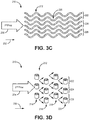
- FIG. 3A is a perspective view of a third embodiment of a heat exchanger
- FIG. 3B is a top view of the heat exchanger in FIG. 3A
- FIG. 3C is an elevation view of the heat exchanger in FIG. 3A
- FIG. 3D is a front view of the heat exchanger in FIG. 3A
- Heat exchanger 210 includes tubes 112 comprising first column 214, second column 216, third column 218, and fourth column 220 as well as first row 222, second row 224, and third row 226.
- Heat exchanger 210 also includes flow void 228, first fluid 120, first direction 232, second fluid 234, and second direction 236.
- the components of heat exchanger 210 are the same as those similarly named with regards to heat exchanger 10 in FIGS.
- each of tubes 212 of heat exchanger 210 have a cross-sectional shape that is oblong.
- Tubes 212 having an oblong cross-sectional shape increases the surface area of each of tubes 212, thereby increasing the thermal energy transfer between first fluid 130 and second fluid 134. Additionally, the pressure drop of second fluid 234 flowing over the oblong tubes, as shown in FIG. 3D , will be less than the pressure drop of second fluid 34 flowing over tubes 12 in FIG. 1D for the same tube cross-sectional area.
- tubes 212 can have a variety of shapes, wave patterns, and configurations/spacing depending on design considerations and thermal energy transfer needs.
- Heat exchanger 10/110/210 that is disclosed herein utilizes a cross-flow configuration to transfer thermal energy between first fluid 30/130/230 and second fluid 34/134/234.
- the cross-flow configuration includes multiple tubes/ducts 12/112/212 that extend in first direction 32/132/232 through flow void 28/128/228.
- First fluid 30/130/230 flows through tubes 12/112/212, and second fluid 34/134/234 flows through flow void 28/128/228 substantially in second direction 36/136/236, which is perpendicular to first direction 32/132/232 and tubes 12/112/232.
- Such a configuration results in the entire surface area of tubes 12/112/232 being primary surface area, thereby increasing the thermal energy transfer capabilities between first fluid 30/130/230 and second fluid 34/134/234.
- Tubes 12/112/212 can have a wave pattern that increases the surface area of tubes 12/112/212 within flow void 28/128/228 by increasing the length of tubes 12/112/212.
- the waves can have a variety of shapes, including waves that are based on a sinusoidal (i.e., cosine or sine) curve.
- tubes 12/112/212 can be a variety of shapes, including tubes 12/112/212 that each have a circular cross-sectional shape (tubes 12 in FIGS. 1A-1D and tubes 112 in FIGS. 2A-2D ) or an oblong cross-sectional shape (tubes 212 in FIGS. 3A-3D ), to increase or decrease the flow area of tubes 12/112/212 and/or the primary surface area of tubes 12/112/212.
- heat exchanger 110 can include a plurality of walls 138 that extend between laterally adjacent tubes 112 substantially in second direction 136 such that the plurality of walls 138 divide flow void 128 into multiple discrete flow channels 140 and 142 through which second fluid 134 can flow.
- Flow void 128 being divided into discrete flow channels 140 and 142 results in heat exchanger 110 experiencing channel flow characteristics in both flow directions, which may be advantageous in some applications.
- walls 138 provide additional surface area through which thermal energy can transfer between first fluid 130 and second fluid 134, thereby increasing the thermal energy transfer between first fluid 130 and second fluid 134 without the addition of volume to flow void 128 and heat exchanger 110.
- the waves of tubes 12/112/212 can have alternate amplitudes, wavelengths, and other characteristics as required for optimal thermal energy transfer and to accommodate a designed flow of first fluid 30/130/230 and/or second fluid 34/134/234. Further, the waves can have a variety of shapes, such as triangular waves with pointed peaks and troughs, rectangular waves with flat tops and bottoms, and/or other configurations.
- a heat exchanger including a plurality of tubes, a header, and a plurality of flow voids.
- the plurality of tubes extends in a first direction through which a first fluid is configured to flow.
- Each of the plurality of tubes have waves that repeat at regular intervals along the first flow direction and are spaced from one another vertically and laterally in the second direction.
- the header extends in the first direction and is attached to each of the plurality of tubes.
- the header is configured to convey the first fluid to each of the plurality of tubes.
- the plurality of flow voids are formed between the plurality of tubes.
- the plurality of flow voids extend in a second direction through which a second fluid is configured to flow such that the second fluid is in thermal contact with the plurality of tubes.
- the heat exchanger of the preceding paragraph can optionally include, additionally and/or alternatively, any one or more of the following features, configurations, and/or additional components:
- the waves of the plurality of tubes are based on a sinusoidal curve.
- the plurality of tubes are arranged vertically in columns with tubes being directly above and below adjacent tubes.
- the plurality of tubes are arranged into at least four columns.
- the plurality of tubes are arranged laterally in rows with tubes being vertically offset from adjacent tubes.
- the plurality of tubes are arranged into at least three rows.
- a cross-sectional shape of each of the plurality of tubes is circular.
- a cross-sectional shape of each of the plurality of tubes is oblong.
- a plurality of walls extending between horizontally adjacent tubes substantially in the second direction with the plurality of walls dividing the flow void into multiple discrete flow channels through which the second fluid is configured to flow.
- the plurality of walls divides the flow void into at least two discrete flow channels.
- Each of the plurality of tubes are vertically offset from one another such that the discrete flow channels form a zig-zag pattern.
- the plurality of tubes, the header, and the plurality of walls are constructed from the same material.
- a heat exchanger includes multiple ducts extending substantially in a first direction and configured to accommodate the flow of a first fluid with each duct of the multiple ducts having a wave pattern and a cross-flow zone extending substantially in a second direction perpendicular to the first direction with the multiple ducts extending through the cross-flow zone.
- the cross-flow zone is configured to accommodate the flow of a second fluid such that the second fluid is in contact with the multiple ducts.
- the heat exchanger of the preceding paragraph can optionally include, additionally and/or alternatively, any one or more of the following features, configurations, and/or additional components:
- the waves of each duct of the multiple ducts are based on a sinusoidal curve.
- Waves of laterally adjacent ducts of the multiple ducts have differing amplitudes.
- the multiple ducts are arranged vertically in columns with ducts being directly above and below adjacent ducts.
- the multiple ducts are arranged laterally in rows with ducts being vertically offset from laterally adjacent ducts.
- a cross-sectional shape of each duct of the multiple ducts is circular.
- a cross-sectional shape of each duct of the multiple ducts is oblong.
- a plurality of walls extending between laterally adjacent ducts substantially in the second direction such that the plurality of walls divide the cross-flow zone into multiple discrete flow channels through which the second fluid is configured to flow.
Landscapes
- Engineering & Computer Science (AREA)
- Physics & Mathematics (AREA)
- Thermal Sciences (AREA)
- Mechanical Engineering (AREA)
- General Engineering & Computer Science (AREA)
- Geometry (AREA)
- Heat-Exchange Devices With Radiators And Conduit Assemblies (AREA)
Applications Claiming Priority (1)
| Application Number | Priority Date | Filing Date | Title |
|---|---|---|---|
| US16/248,271 US10890381B2 (en) | 2019-01-15 | 2019-01-15 | Cross-flow heat exchanger |
Publications (2)
| Publication Number | Publication Date |
|---|---|
| EP3683531A1 true EP3683531A1 (de) | 2020-07-22 |
| EP3683531B1 EP3683531B1 (de) | 2026-04-15 |
Family
ID=69167738
Family Applications (1)
| Application Number | Title | Priority Date | Filing Date |
|---|---|---|---|
| EP20151748.9A Active EP3683531B1 (de) | 2019-01-15 | 2020-01-14 | Kreuzstromwärmetauscher |
Country Status (2)
| Country | Link |
|---|---|
| US (2) | US10890381B2 (de) |
| EP (1) | EP3683531B1 (de) |
Families Citing this family (7)
| Publication number | Priority date | Publication date | Assignee | Title |
|---|---|---|---|---|
| US10890381B2 (en) * | 2019-01-15 | 2021-01-12 | Hamilton Sundstrand Corporation | Cross-flow heat exchanger |
| US11274602B2 (en) * | 2019-05-24 | 2022-03-15 | Pratt & Whitney Canada Corp. | Air cooler for gas turbine engine |
| US11555659B2 (en) * | 2020-12-18 | 2023-01-17 | Hamilton Sundstrand Corporation | Multi-scale heat exchanger core |
| AU2021416859A1 (en) * | 2021-01-11 | 2023-07-13 | Conflux Technology Pty Ltd | Heat exchanger |
| US20220412658A1 (en) * | 2021-06-23 | 2022-12-29 | Hamilton Sundstrand Corporation | Wavy adjacent passage heat exchanger core |
| US12421897B2 (en) * | 2022-07-15 | 2025-09-23 | Rtx Corporation | Aircraft heat exchanger |
| US12152839B2 (en) * | 2022-10-06 | 2024-11-26 | Rtx Corporation | Tube heat exchanger using 3-tube bundles |
Citations (5)
| Publication number | Priority date | Publication date | Assignee | Title |
|---|---|---|---|---|
| EP1548386A1 (de) * | 2002-08-28 | 2005-06-29 | Toyo Radiator Co., Ltd. | Agr-kühler |
| WO2008058734A1 (de) * | 2006-11-15 | 2008-05-22 | Behr Gmbh & Co. Kg | Wärmeübertrager für kraftfahrzeug mit stranggepresstem gekrümmten strömungskanal |
| CN107504850A (zh) * | 2017-08-31 | 2017-12-22 | 中国石油大学(华东) | 一种异型管式换热器 |
| EP3312538A1 (de) * | 2016-10-20 | 2018-04-25 | Hamilton Sundstrand Corporation | Rippenrohrwärmetauscher |
| DE112017001354T5 (de) * | 2016-03-16 | 2018-11-29 | Mitsubishi Electric Corporation | Lamellenfreier wärmetauscher, aussenraumeinheit einer klimaanlagenvorrichtung, die den lamellenfreien wärmetauscher aufweist, und innenraumeinheit einer klimaanlagenvorrichtung, die den lamellenfreien wärmetauscher aufweist |
Family Cites Families (24)
| Publication number | Priority date | Publication date | Assignee | Title |
|---|---|---|---|---|
| US4293033A (en) | 1979-06-29 | 1981-10-06 | Linde Aktiengesellschaft | Plate-type heat exchanger |
| DE3220774C2 (de) | 1982-06-02 | 1986-09-25 | W. Schmidt GmbH & Co KG, 7518 Bretten | Plattenverdampfer oder -kondensator |
| JPS61262593A (ja) | 1985-05-15 | 1986-11-20 | Showa Alum Corp | 熱交換器 |
| US4919200A (en) | 1989-05-01 | 1990-04-24 | Stanislas Glomski | Heat exchanger wall assembly |
| DE102004011608A1 (de) * | 2004-03-18 | 2005-10-13 | Obrist Engineering Gmbh | Wärmetauscher einer Fahrzeugklimaanlage |
| GB0427362D0 (en) | 2004-12-14 | 2005-01-19 | Sustainable Engine Systems Ltd | Heat exchanger |
| US7254953B2 (en) | 2005-01-06 | 2007-08-14 | Caterpillar Inc | Thermoelectric heat exchange element |
| JP2007113793A (ja) | 2005-10-17 | 2007-05-10 | Calsonic Kansei Corp | エバポレータ |
| JP4994450B2 (ja) | 2007-06-18 | 2012-08-08 | 三菱電機株式会社 | 熱交換素子およびその製造方法ならびに熱交換器および熱交換換気装置 |
| US8568495B2 (en) | 2008-09-05 | 2013-10-29 | Samsung Sdi Co., Ltd. | Evaporator and fuel reformer having the same |
| DE102009052045A1 (de) | 2009-11-05 | 2011-05-12 | Rvt Process Equipment Gmbh | Gewelltes Packungsgitter sowie geordnete, aus mehreren Packungsgittern aufgebaute Packung |
| GB201121754D0 (en) | 2011-12-19 | 2012-02-01 | Rolls Royce Plc | A heat exchanger |
| EP2711163A1 (de) | 2012-09-21 | 2014-03-26 | Hirschberg Engineering | Dreidimensionale Formkörper |
| US11162424B2 (en) * | 2013-10-11 | 2021-11-02 | Reaction Engines Ltd | Heat exchangers |
| US10809016B2 (en) | 2015-02-06 | 2020-10-20 | Raytheon Technologies Corporation | Heat exchanger system with additively manufactured heat transfer tube that follows a non-linear path |
| US11112183B2 (en) | 2016-01-14 | 2021-09-07 | Hamilton Sundstrand Corporation | Heat exchanger channels |
| CN107036479B (zh) | 2016-02-04 | 2020-05-12 | 丹佛斯微通道换热器(嘉兴)有限公司 | 换热板以及使用其的板式换热器 |
| US10605544B2 (en) | 2016-07-08 | 2020-03-31 | Hamilton Sundstrand Corporation | Heat exchanger with interleaved passages |
| GB2552956A (en) | 2016-08-15 | 2018-02-21 | Hs Marston Aerospace Ltd | Heat exchanger device |
| US10704841B2 (en) | 2017-01-03 | 2020-07-07 | Titan Tensor LLC | Monolithic bicontinuous labyrinth structures and methods for their manufacture |
| US11090225B2 (en) | 2018-03-08 | 2021-08-17 | Thaddeus Medical Systems, Inc. | Protection device that promotes air flow for heat transfer |
| US10932395B2 (en) | 2018-06-04 | 2021-02-23 | GM Global Technology Operations LLC | Thermal management device for use on electronics in a transportation vehicle |
| US20200033070A1 (en) | 2018-07-25 | 2020-01-30 | Andreas Vlahinos | Minimal surface heat exchanger |
| US10890381B2 (en) * | 2019-01-15 | 2021-01-12 | Hamilton Sundstrand Corporation | Cross-flow heat exchanger |
-
2019
- 2019-01-15 US US16/248,271 patent/US10890381B2/en active Active
-
2020
- 2020-01-14 EP EP20151748.9A patent/EP3683531B1/de active Active
- 2020-12-09 US US17/116,087 patent/US11448466B2/en active Active
Patent Citations (5)
| Publication number | Priority date | Publication date | Assignee | Title |
|---|---|---|---|---|
| EP1548386A1 (de) * | 2002-08-28 | 2005-06-29 | Toyo Radiator Co., Ltd. | Agr-kühler |
| WO2008058734A1 (de) * | 2006-11-15 | 2008-05-22 | Behr Gmbh & Co. Kg | Wärmeübertrager für kraftfahrzeug mit stranggepresstem gekrümmten strömungskanal |
| DE112017001354T5 (de) * | 2016-03-16 | 2018-11-29 | Mitsubishi Electric Corporation | Lamellenfreier wärmetauscher, aussenraumeinheit einer klimaanlagenvorrichtung, die den lamellenfreien wärmetauscher aufweist, und innenraumeinheit einer klimaanlagenvorrichtung, die den lamellenfreien wärmetauscher aufweist |
| EP3312538A1 (de) * | 2016-10-20 | 2018-04-25 | Hamilton Sundstrand Corporation | Rippenrohrwärmetauscher |
| CN107504850A (zh) * | 2017-08-31 | 2017-12-22 | 中国石油大学(华东) | 一种异型管式换热器 |
Also Published As
| Publication number | Publication date |
|---|---|
| US10890381B2 (en) | 2021-01-12 |
| US20200224974A1 (en) | 2020-07-16 |
| EP3683531B1 (de) | 2026-04-15 |
| US20210088285A1 (en) | 2021-03-25 |
| US11448466B2 (en) | 2022-09-20 |
Similar Documents
| Publication | Publication Date | Title |
|---|---|---|
| EP3683531B1 (de) | Kreuzstromwärmetauscher | |
| US11454448B2 (en) | Enhanced heat transfer surface | |
| US10048020B2 (en) | Heat transfer surfaces with flanged apertures | |
| KR102243230B1 (ko) | 열전달 판 및 판 열교환기 | |
| US6273183B1 (en) | Heat exchanger turbulizers with interrupted convolutions | |
| US9766015B2 (en) | Heat exchanger | |
| US20140091453A1 (en) | Cooling device and semiconductor device | |
| JP4584976B2 (ja) | 熱交換プレートおよびプレートパッケージ | |
| JP2010203694A (ja) | 液冷式冷却装置 | |
| US20020195239A1 (en) | Heat exchanger | |
| EP3040670A1 (de) | Wärmeübertrager, insbesondere ein kondensator oder ein gaskühler | |
| EA030192B1 (ru) | Теплообменник | |
| JP2018521293A (ja) | 熱交換器用フィン組立体およびフィン組立体を有する熱交換器 | |
| US20040144525A1 (en) | Heat exchanger with brazed plates | |
| JP2013537298A (ja) | 冷媒導管とその冷媒導管を備えた熱交換器 | |
| KR20160042182A (ko) | 열교환기용 튜브 | |
| CN104034190A (zh) | 双点波图案的热交换器 | |
| EP0415584B1 (de) | Stapelverdampfer | |
| JP2015113983A (ja) | 熱交換器 | |
| JP5162538B2 (ja) | 液冷式冷却装置 | |
| JP6592930B2 (ja) | 熱交換器 | |
| EA030173B1 (ru) | Каталитический реактор | |
| EP2064509A1 (de) | Wärmeübertragungsflächen mit flansch-öffnungen | |
| KR102164292B1 (ko) | 인쇄기판형 열교환기 및 이를 포함하는 열교환 장치 | |
| US20210003352A1 (en) | Heat exchanger |
Legal Events
| Date | Code | Title | Description |
|---|---|---|---|
| PUAI | Public reference made under article 153(3) epc to a published international application that has entered the european phase |
Free format text: ORIGINAL CODE: 0009012 |
|
| STAA | Information on the status of an ep patent application or granted ep patent |
Free format text: STATUS: THE APPLICATION HAS BEEN PUBLISHED |
|
| AK | Designated contracting states |
Kind code of ref document: A1 Designated state(s): AL AT BE BG CH CY CZ DE DK EE ES FI FR GB GR HR HU IE IS IT LI LT LU LV MC MK MT NL NO PL PT RO RS SE SI SK SM TR |
|
| AX | Request for extension of the european patent |
Extension state: BA ME |
|
| STAA | Information on the status of an ep patent application or granted ep patent |
Free format text: STATUS: REQUEST FOR EXAMINATION WAS MADE |
|
| 17P | Request for examination filed |
Effective date: 20210119 |
|
| RBV | Designated contracting states (corrected) |
Designated state(s): AL AT BE BG CH CY CZ DE DK EE ES FI FR GB GR HR HU IE IS IT LI LT LU LV MC MK MT NL NO PL PT RO RS SE SI SK SM TR |
|
| STAA | Information on the status of an ep patent application or granted ep patent |
Free format text: STATUS: EXAMINATION IS IN PROGRESS |
|
| 17Q | First examination report despatched |
Effective date: 20240514 |
|
| GRAP | Despatch of communication of intention to grant a patent |
Free format text: ORIGINAL CODE: EPIDOSNIGR1 |
|
| STAA | Information on the status of an ep patent application or granted ep patent |
Free format text: STATUS: GRANT OF PATENT IS INTENDED |
|
| INTG | Intention to grant announced |
Effective date: 20251110 |
|
| GRAS | Grant fee paid |
Free format text: ORIGINAL CODE: EPIDOSNIGR3 |
|
| GRAA | (expected) grant |
Free format text: ORIGINAL CODE: 0009210 |
|
| STAA | Information on the status of an ep patent application or granted ep patent |
Free format text: STATUS: THE PATENT HAS BEEN GRANTED |
|
| AK | Designated contracting states |
Kind code of ref document: B1 Designated state(s): AL AT BE BG CH CY CZ DE DK EE ES FI FR GB GR HR HU IE IS IT LI LT LU LV MC MK MT NL NO PL PT RO RS SE SI SK SM TR |
|
| REG | Reference to a national code |
Ref country code: CH Ref legal event code: F10 Free format text: ST27 STATUS EVENT CODE: U-0-0-F10-F00 (AS PROVIDED BY THE NATIONAL OFFICE) Effective date: 20260415 |