EP3683536B1 - Acquisition de cibles - Google Patents
Acquisition de cibles Download PDFInfo
- Publication number
- EP3683536B1 EP3683536B1 EP19000597.5A EP19000597A EP3683536B1 EP 3683536 B1 EP3683536 B1 EP 3683536B1 EP 19000597 A EP19000597 A EP 19000597A EP 3683536 B1 EP3683536 B1 EP 3683536B1
- Authority
- EP
- European Patent Office
- Prior art keywords
- heat
- target
- target body
- emitting
- simulation
- Prior art date
- Legal status (The legal status is an assumption and is not a legal conclusion. Google has not performed a legal analysis and makes no representation as to the accuracy of the status listed.)
- Active
Links
Images


Classifications
-
- F—MECHANICAL ENGINEERING; LIGHTING; HEATING; WEAPONS; BLASTING
- F41—WEAPONS
- F41J—TARGETS; TARGET RANGES; BULLET CATCHERS
- F41J2/00—Reflecting targets, e.g. radar-reflector targets; Active targets transmitting electromagnetic or acoustic waves
- F41J2/02—Active targets transmitting infrared radiation
Definitions
- the invention relates to a method for zeroing a firearm with a target device that enables a thermal image to be captured, in particular of a rifle, with an appropriate target simulation being arranged at a distance from the firearm, according to the preamble of claim 1, and a device according to the preamble of claim 7.
- telescopic sights or other night vision devices for shooting in the dark, which react to infrared light, ie can detect thermal radiation emitted, for example by an animal.
- the target is not optically visible in the dark.
- U.S. 6,337,475 B1 shows a heatable target silhouette that has a copper foil on the back and a heating coil and requires a power source such as a 1.5 V battery to operate. Since the target silhouette has relatively large dimensions, such a target silhouette is very expensive, bulky and heavy. It is therefore very difficult to take it with you on hunting missions in nature, which usually require some walking.
- U.S. 6,767,015 B1 shows a heatable target in the shape and size of a human torso, giving the target significant proportions.
- a plurality of heated cells are provided, arranged within a closed housing. All cells are arranged in a common, large vacuum container, which must be airtight and must be evacuated before use. A vacuum pump is therefore required, which is active in cell production. After opening the container, all cells are activated together. Therefore, the disadvantages mentioned above with regard to mass, size and bulkiness are particularly pronounced with this target, making the equipment expenditure excessively large and difficult for hunters to cope with.
- U.S. 2017/350678 A1 discloses a target simulation to which an infrared reflective element or a thermal reflective element can be adhered, to be manufactured from roll or sheet material and having dimensions in the range of less than 25.4 mm on an edge.
- the invention is based on the problem of providing a simple and inexpensive way of calibrating a target detection system based on thermal radiation, even when visibility is poor or absent.
- the invention solves this problem by a method having the features of claim 1, which of course can be used not only in the dark but also when visibility is available, and by a device having the features of claim 7. Regarding further developments of the invention referred to the dependent claims.
- the target simulation is provided with a heat-emitting target body with a maximum edge length or a maximum diameter of less than or equal to 40 millimeters, the target body being provided or filled with a substance that reacts exothermically with air , possible, even in the absence of visibility, for example in the dark, to enable calibration of the thermal imaging.
- the heat radiation from the target body can be detected, for example, using a thermal imaging night vision device, which can also be designed as a telescopic sight.
- such a target body has a temperature of approx. 35° C. to more than 50° C. and can maintain this temperature for several hours. It can be designed as a disposable body and be self-adhesive on at least one side.
- the heat-dissipating target body is preferably designed in the manner of a plaster and, according to the invention, it is glued onto, for example, a target card known per se.
- a target card known per se.
- Such a rather flat radiator is also referred to as a heating pad.
- the heat-emitting target body can advantageously be provided or filled with a substance in the manner of a hand warmer.
- the heat-emitting target body it is possible inexpensively for the heat-emitting target body to contain iron powder, which reacts with atmospheric oxygen in an exothermic reaction to form iron oxide. Then tearing open an airtight package of the target body is enough to start the heat dissipation.
- Such target bodies are advantageously disposable products. They can be held particularly advantageously in vacuum packs that can be torn off individually. These form, for example, connected strips of 5 to 20 pieces.
- the heat-dissipating target body very favorably has a regular geometric outline, for example a circle, a square or a hexagon, so that from a distance (typically up to more than 100 meters) it has an approximately punctiform appearance and symmetry.
- the heat-emitting target body should be relatively small and have maximum edge lengths of less than 30 millimeters in particular.
- target bodies are cut to size before it is attached to the target card and is thus brought to the desired size and outline shape. It is also possible for target bodies to be of different sizes and shapes (e.g. squares with side lengths of 40 millimeters, squares with side lengths of 30 millimeters, circles with diameters of 20 millimeters).
- the heat-dissipating target body can be glued to the center of a target card, which, for example, has an edge length of 20 to 30 centimeters, before use, so that even slightly offset shots hit the surrounding target card and thus their deviation when the target card is subsequently evaluated are visible.
- the heat-emitting target body is additionally provided with a phosphorescent and/or fluorescent substance and emits light in the visible range
- optical recognition of the target body can also be possible in addition or as an alternative.
- Optical target detection can then also take place, for example via residual light target detection.
- a target simulation with at least one heat-emitting target body for calibrating a firearm with a target device that enables a thermal image to be recorded, in particular a rifle equipped in this way, is claimed separately.
- the target body can be made up independently of, for example, target maps or other parts of the target simulation.
- the claimed target simulation can also only consist of a target body, which can be glued or nailed, for example.
- such a heat-dissipating target body can have a plaster-like design and be fastened or fastenable to the center of a target card.
- the target body is provided with a self-adhesive backing for this purpose.
- the target body is in particular regularly geometrically shaped, for example square or round, so that the deviations of the actual from the desired trajectory can be tracked in any direction with equal value.
- the heat-emitting target body is provided or filled with a substance in the manner of a hand warmer and, according to the invention, reacts exothermically with air to enable heat emission. Further action, such as an electrical voltage or moistening, is then not required. Operation is tool-free and particularly easy.
- the heat-emitting target body can be kept in an airtight packaging until it is used, which in particular provides an airtight compartment for each individual target body.
- the target bodies can then be removed individually and activated as required.
- a method for calibrating a thermal image acquisition of a firearm, in particular a rifle is schematically indicated, the rifle--itself not shown--being fired here from a raised position 2, which of course is not mandatory, onto a target simulation 1.
- the method can be carried out in daylight or, in particular, also in fog, darkness or other restricted visibility.
- such a firearm is first sighted and, if necessary, also optimized with regard to thermal imaging. If hunting is then to take place the following night, the thermal imaging is then calibrated in the dark using the method mentioned.
- the firearm is equipped with a thermal imaging system that works, for example, with the aid of a night vision sight or a thermal imaging sight. Fine adjustments can be made in any direction, for example a monitor that can display a thermal image optically.
- Zeroing in and the associated calibration is understood here to mean any shooting at a target simulation 1 .
- This can also be movable, for example - not shown here - for example via a motor drive.
- the calibration does not have to be at the beginning of a hunt, but can also be carried out again and again in between.
- a (fixed or moving) target simulation 1 to be hit is arranged at a distance from the firearm.
- the distance can correspond to that which corresponds to the usual hunting and shooting conditions, ie typically 50 meters to well over 100 meters in the horizontal direction.
- This target simulation 1 is functionally provided with at least one heat-emitting target body 3 - or consists of this - which is glued, for example, to a target card 4 in the center thereof.
- the use of a destination card 4 is of course not mandatory.
- the target body 3 can also represent a target simulation 1 by itself.
- the target body 3 or the target card 4 holding it can in turn be fixed to a tree 5, a fence or some other mount.
- the type of fixing is variable: for example, simply gluing or nailing is an option.
- the heat-emitting target body 3 Due to the heat-emitting target body 3, this can also be detected from a great distance via infrared detection, for example via a night vision sight or a thermal imaging sight, even if there is no or too little light in the visible range.
- a separate night vision device and/or, in particular, a telescopic sight with infrared detection on the firearm can be used in order to detect the heat signal (infrared radiation) over the distance.
- the temperature of the target body 3 is preferably above 35°C in operation. During the chemical reaction mentioned, temperatures of approx. 50°C occur over a period of 6 to 24 hours.
- the target simulation 1 After the target simulation 1 has been placed, several shots are fired at the heat body 3 along the line of fire 6 drawn in dashed lines; then the shooter or other person goes to the target card and looks at where (of the target body 3 or the surrounding target card 4) the shots landed.
- the deviation can be used to correct the calibration of the thermal image acquisition, for example the fine adjustment of a monitor for the thermal image.
- the thermal image then depicts reality exactly, so that the firearm can then be used with pinpoint accuracy. It may be necessary to zero in several times with the calibration mentioned.
- the target bodies 3 can be shot at themselves, this is not critical.
- the heat-emitting target body 3 can be designed in the manner of a plaster, with the rear side, which is glued to the target card 4, for example, being able to be self-adhesive for easy handling, but not necessarily.
- a protective film on the adhesive surface 9 can be removed on site.
- the heat-emitting target body 3 can, for example, be provided with or filled with a substance in the manner of a hand warmer.
- the heat-emitting target body 3 can contain iron powder or another material that reacts with atmospheric oxygen in an exothermic reaction to form iron oxide or another oxide.
- the release of heat then starts automatically through the supply of oxygen from the air, i.e. through opening the packaging. In this case, it makes sense to keep the target bodies 3 individually in airtight packaging until they are used.
- a single airtight compartment can be provided for each target body 3; these can be in the form of continuous tear-off strips, for example via perforations.
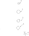
- the heat-dissipating target body 3 advantageously has a regular geometric outline shape, such as a circular, square, hexagonal or octagonal shape. In 4 a few such forms are indicated.
- the edge length 7 or the diameter 8 is in particular less than 40 millimeters in order to avoid excessively broad and spongy heat radiation. Edge lengths of approx. 30 millimeters are particularly favorable.
- a narrow, unfilled seam of a pad or the like can also be provided around the target body 3 . This can have a thickness of about 3 to 8 millimeters.
- a heat-dissipating target body 3 is offered in different dimensions and external outline shapes and can be used directly to fit.
- target bodies 3 can either be completely separated from the start or separated from one another at a perforation and glued to the center of a target card 4 directly before use.
- Such target bodies 3 can have a thickness of, for example, a few millimeters to about 10 millimeters, such as in 3 is visible.
- the target body 3 need not have an exact rectangular shape, but may exhibit a slight pillow shape and deformability.
- the heat-emitting target body can additionally be provided with a phosphorescent and/or fluorescent substance and can also emit light in the visible range. This makes it easier to check the correct trajectory 6. A longer afterglow is also possible.
Landscapes
- Engineering & Computer Science (AREA)
- Physics & Mathematics (AREA)
- Electromagnetism (AREA)
- Radar, Positioning & Navigation (AREA)
- Remote Sensing (AREA)
- General Engineering & Computer Science (AREA)
- Aiming, Guidance, Guns With A Light Source, Armor, Camouflage, And Targets (AREA)
- Telescopes (AREA)
Claims (13)
- Procédé de réglage d'une arme à feu, en particulier d'un fusil, avec un dispositif de cible qui permet une acquisition d'une image par rayonnement thermique, dans lequel une simulation de cible (1) à atteindre est agencée à une distance de l'arme à feu, dans lequel un corps de cible (3) exothermique est collé sur la simulation de cible (1), lequel présente des longueurs d'arête (7) maximales ou un diamètre (8) maximal égal ou inférieur à 40 millimètres,
caractérisé en ce que
le corps de cible (3) exothermique est pourvu ou rempli d'une substance qui réagit de manière exothermique avec l'air. - Procédé selon la revendication 1,
caractérisé en ce que
le corps de cible (3) exothermique est réalisé comme un pavé. - Procédé selon l'une quelconque des revendications 1 à 2,
caractérisé en ce que
le corps de cible (3) exothermique contient de la poudre de fer ou un autre matériau qui réagit avec l'oxygène atmosphérique dans une réaction exothermique pour former un oxyde de fer ou un autre oxyde. - Procédé selon l'une quelconque des revendications 1 à 3,
caractérisé en ce que
le corps de cible (3) exothermique présente une forme de profil géométrique régulière, en particulier rectangulaire ou ronde. - Procédé selon l'une quelconque des revendications 1 à 4,
caractérisé en ce que
le corps de cible (3) exothermique présente des longueurs d'arête (7) maximales ou un diamètre (8) de moins de 30 millimètres. - Procédé selon l'une quelconque des revendications 1 à 5,
caractérisé en ce que
le corps de cible (3) exothermique est collé avant l'utilisation dans le centre d'une carte de cible (4). - Simulation de cible (1) pour le réglage d'une arme à feu, en particulier d'un fusil, avec un dispositif de cible qui permet une acquisition d'une image par rayonnement thermique, dans laquelle la simulation de cible (1) comporte au moins un corps de cible (3) collé et exothermique en fonction qui présente des longueurs d'arête (7) maximales ou un diamètre maximal (8) égal ou inférieur à 40 millimètres,
caractérisée en ce que
le corps de cible (3) exothermique est pourvu ou rempli d'une substance qui réagit de manière exothermique avec l'air. - Simulation de cible (1) selon la revendication 7,
caractérisée en ce que
le corps de cible (3) exothermique est réalisé comme un pavé et est ou peut être fixé au centre d'une carte de cible (4). - Simulation de cible (1) selon l'une quelconque des revendications 7 à 8,
caractérisée en ce que
le corps de cible (3) exothermique présente des longueurs d'arête (7) maximales ou un diamètre (8) maximal de moins de 30 millimètres. - Simulation de cible (1) selon l'une quelconque des revendications 7 à 9,
caractérisée en ce que
le corps de cible (3) exothermique est maintenu jusqu'à l'insertion dans un emballage étanche à l'air. - Simulation de cible (1) selon la revendication 10,
caractérisée en ce que
l'emballage étanche à l'air comporte une pluralité de compartiments individuellement déchirables. - Simulation de cible (1) selon l'une quelconque des revendications 7 à 11,
caractérisée en ce que
le corps de cible (3) exothermique est autocollant. - Simulation de cible (1) selon l'une quelconque des revendications 7 à 12,
caractérisée en ce que
le corps de cible (3) exothermique est en outre pourvu d'une substance phosphorescente et/ou fluorescente et émet de la lumière dans la plage visible.
Applications Claiming Priority (1)
| Application Number | Priority Date | Filing Date | Title |
|---|---|---|---|
| DE102019000225.3A DE102019000225A1 (de) | 2019-01-16 | 2019-01-16 | Zielerfassung |
Publications (3)
| Publication Number | Publication Date |
|---|---|
| EP3683536A1 EP3683536A1 (fr) | 2020-07-22 |
| EP3683536B1 true EP3683536B1 (fr) | 2023-06-07 |
| EP3683536C0 EP3683536C0 (fr) | 2023-06-07 |
Family
ID=69104195
Family Applications (1)
| Application Number | Title | Priority Date | Filing Date |
|---|---|---|---|
| EP19000597.5A Active EP3683536B1 (fr) | 2019-01-16 | 2019-12-28 | Acquisition de cibles |
Country Status (2)
| Country | Link |
|---|---|
| EP (1) | EP3683536B1 (fr) |
| DE (1) | DE102019000225A1 (fr) |
Families Citing this family (2)
| Publication number | Priority date | Publication date | Assignee | Title |
|---|---|---|---|---|
| DE102019000225A1 (de) | 2019-01-16 | 2020-07-16 | André Roekens | Zielerfassung |
| US20240377166A1 (en) * | 2023-05-11 | 2024-11-14 | Christopher M. Thompson | Thermal shooting targets and systems |
Family Cites Families (9)
| Publication number | Priority date | Publication date | Assignee | Title |
|---|---|---|---|---|
| GB2184215B (en) * | 1985-10-15 | 1988-08-10 | Fulmer Res Inst Ltd | Improvements in or relating to a thermal image target |
| US6337475B1 (en) * | 2000-02-24 | 2002-01-08 | The United States Of America As Represented By The Secretary Of The Army | Thermal silhouette target and zeroing technique |
| DE10150069A1 (de) * | 2001-10-10 | 2003-04-30 | Bundesrep Deutschland | Wärmebildfähige Zielscheibe |
| US6767015B1 (en) * | 2003-06-05 | 2004-07-27 | The United States Of America As Represented By The Secretary Of The Navy | Thermal target |
| US7528397B2 (en) * | 2006-03-31 | 2009-05-05 | Boyer Thomas R | Thermal infrared signage method with application to infrared weapon sight calibration |
| US20110175292A1 (en) * | 2008-02-07 | 2011-07-21 | Carni Anthony R | Thermal Signature Target |
| US20120218633A1 (en) * | 2011-02-24 | 2012-08-30 | Cincotti K Dominic | Targets, target training systems, and methods |
| US10228219B2 (en) * | 2016-06-06 | 2019-03-12 | Boyer Thomas R | Universal weapon zeroing target |
| DE102019000225A1 (de) | 2019-01-16 | 2020-07-16 | André Roekens | Zielerfassung |
-
2019
- 2019-01-16 DE DE102019000225.3A patent/DE102019000225A1/de not_active Withdrawn
- 2019-12-28 EP EP19000597.5A patent/EP3683536B1/fr active Active
Also Published As
| Publication number | Publication date |
|---|---|
| DE102019000225A1 (de) | 2020-07-16 |
| EP3683536C0 (fr) | 2023-06-07 |
| EP3683536A1 (fr) | 2020-07-22 |
Similar Documents
| Publication | Publication Date | Title |
|---|---|---|
| DE102013019098B3 (de) | System zum Erfassen von Parametern der Umwelt und Umgebung | |
| DE102020128610A1 (de) | Mikropunktvisier mit einem dualemitter | |
| EP2579709A2 (fr) | Étiquette d'identification pour animaux | |
| EP3683536A1 (fr) | Acquisition de cibles | |
| DE102009009082A1 (de) | Wirkmittelwurfsystem zum Abschuss nicht-letaler Wirkmittel von einem Fahrzeug, insbesondere einem Polizei-oder Militärfahrzeug | |
| DE112020002404T5 (de) | Proportional reagierende konduktive Energiewaffe sowie Verfahren | |
| DE102018128002A1 (de) | Verfahren zur Bodenabtastung mit Hilfe einer (Drehflügel)-Flugdrohne | |
| DE202016004550U1 (de) | 3D-Messgerät | |
| DE2655306C3 (de) | Verfahren und Vorrichtung zur Ausblendung von Störstrahlern in einer Einrichtung zur optischen Lenkung von Flugkörpern | |
| DE202019000992U1 (de) | Zielerfassung bei insbesondere Dunkelheit | |
| DE1261019B (de) | Einrichtung zur Trefferermittlung bei militaerischen Manoevern | |
| EP3118561B1 (fr) | Systeme a energie dirigee et systeme d'arme | |
| DE102022130560B4 (de) | Verfahren und Vorrichtung zur Abwehr von Luftfahrzeugen, insbesondere von unbemannten Luftfahrzeugen | |
| DE102020004487A1 (de) | Wirkmittel zur Bekämpfung eines Ziels | |
| EP2362208A1 (fr) | Dispositif de mesure destiné à la mesure de la bioluminescence, chimioluminescence ou fluorescence d'objets, dispositif de rayonnement, système de mesure et procédé d'observation de plantes | |
| DE1489750B2 (de) | Strahlungsdetektor zum sichtbarmachen und betrachten von un sichtbaren strahlen | |
| DE102012002687A1 (de) | Granate mit einem Markierungsstoff | |
| DE2240598C3 (de) | Vorrichtung mit Radargerät, Laser-Entfernungsmesser und Infrarot-Zielverfolgungsgerät zur Feind-Flugobjekt-Vermessung und -Verfolgung | |
| DE3127844C2 (de) | Verfahen zum Abwerfen von Munition von einem Kampfflugzeug aus | |
| DE298537C (fr) | ||
| DE2411791C3 (de) | Verfahren zum Bekämpfen von Bodenzielen mittels lenkbarer Geschosse | |
| DE8909166U1 (de) | Tränengaspatrone | |
| CH720466A1 (de) | Messvorrichtungsgehäuse zur Befestigung an Fortbewegungsmittel | |
| WO2001092814A2 (fr) | Cartouche, dispositif de tir permettant de tirer des cartouches, et procede de fabrication d'une cartouche | |
| EP3987929A1 (fr) | Procédé de pulvérisation d'un agent de pulvérisation au moyen d'un pulvérisateur agricole |
Legal Events
| Date | Code | Title | Description |
|---|---|---|---|
| PUAI | Public reference made under article 153(3) epc to a published international application that has entered the european phase |
Free format text: ORIGINAL CODE: 0009012 |
|
| STAA | Information on the status of an ep patent application or granted ep patent |
Free format text: STATUS: THE APPLICATION HAS BEEN PUBLISHED |
|
| AK | Designated contracting states |
Kind code of ref document: A1 Designated state(s): AL AT BE BG CH CY CZ DE DK EE ES FI FR GB GR HR HU IE IS IT LI LT LU LV MC MK MT NL NO PL PT RO RS SE SI SK SM TR |
|
| AX | Request for extension of the european patent |
Extension state: BA ME |
|
| STAA | Information on the status of an ep patent application or granted ep patent |
Free format text: STATUS: REQUEST FOR EXAMINATION WAS MADE |
|
| 17P | Request for examination filed |
Effective date: 20210119 |
|
| RBV | Designated contracting states (corrected) |
Designated state(s): AL AT BE BG CH CY CZ DE DK EE ES FI FR GB GR HR HU IE IS IT LI LT LU LV MC MK MT NL NO PL PT RO RS SE SI SK SM TR |
|
| STAA | Information on the status of an ep patent application or granted ep patent |
Free format text: STATUS: EXAMINATION IS IN PROGRESS |
|
| 17Q | First examination report despatched |
Effective date: 20220809 |
|
| GRAP | Despatch of communication of intention to grant a patent |
Free format text: ORIGINAL CODE: EPIDOSNIGR1 |
|
| STAA | Information on the status of an ep patent application or granted ep patent |
Free format text: STATUS: GRANT OF PATENT IS INTENDED |
|
| INTG | Intention to grant announced |
Effective date: 20220920 |
|
| GRAS | Grant fee paid |
Free format text: ORIGINAL CODE: EPIDOSNIGR3 |
|
| GRAA | (expected) grant |
Free format text: ORIGINAL CODE: 0009210 |
|
| STAA | Information on the status of an ep patent application or granted ep patent |
Free format text: STATUS: THE PATENT HAS BEEN GRANTED |
|
| TPAC | Observations filed by third parties |
Free format text: ORIGINAL CODE: EPIDOSNTIPA |
|
| AK | Designated contracting states |
Kind code of ref document: B1 Designated state(s): AL AT BE BG CH CY CZ DE DK EE ES FI FR GB GR HR HU IE IS IT LI LT LU LV MC MK MT NL NO PL PT RO RS SE SI SK SM TR |
|
| REG | Reference to a national code |
Ref country code: GB Ref legal event code: FG4D Free format text: NOT ENGLISH |
|
| REG | Reference to a national code |
Ref country code: CH Ref legal event code: EP Ref country code: AT Ref legal event code: REF Ref document number: 1576311 Country of ref document: AT Kind code of ref document: T Effective date: 20230615 |
|
| REG | Reference to a national code |
Ref country code: DE Ref legal event code: R096 Ref document number: 502019007837 Country of ref document: DE |
|
| U01 | Request for unitary effect filed |
Effective date: 20230705 |
|
| U07 | Unitary effect registered |
Designated state(s): AT BE BG DE DK EE FI FR IT LT LU LV MT NL PT SE SI Effective date: 20230714 |
|
| REG | Reference to a national code |
Ref country code: LT Ref legal event code: MG9D |
|
| PG25 | Lapsed in a contracting state [announced via postgrant information from national office to epo] |
Ref country code: NO Free format text: LAPSE BECAUSE OF FAILURE TO SUBMIT A TRANSLATION OF THE DESCRIPTION OR TO PAY THE FEE WITHIN THE PRESCRIBED TIME-LIMIT Effective date: 20230907 Ref country code: ES Free format text: LAPSE BECAUSE OF FAILURE TO SUBMIT A TRANSLATION OF THE DESCRIPTION OR TO PAY THE FEE WITHIN THE PRESCRIBED TIME-LIMIT Effective date: 20230607 |
|
| PG25 | Lapsed in a contracting state [announced via postgrant information from national office to epo] |
Ref country code: RS Free format text: LAPSE BECAUSE OF FAILURE TO SUBMIT A TRANSLATION OF THE DESCRIPTION OR TO PAY THE FEE WITHIN THE PRESCRIBED TIME-LIMIT Effective date: 20230607 Ref country code: HR Free format text: LAPSE BECAUSE OF FAILURE TO SUBMIT A TRANSLATION OF THE DESCRIPTION OR TO PAY THE FEE WITHIN THE PRESCRIBED TIME-LIMIT Effective date: 20230607 Ref country code: GR Free format text: LAPSE BECAUSE OF FAILURE TO SUBMIT A TRANSLATION OF THE DESCRIPTION OR TO PAY THE FEE WITHIN THE PRESCRIBED TIME-LIMIT Effective date: 20230908 |
|
| PG25 | Lapsed in a contracting state [announced via postgrant information from national office to epo] |
Ref country code: SK Free format text: LAPSE BECAUSE OF FAILURE TO SUBMIT A TRANSLATION OF THE DESCRIPTION OR TO PAY THE FEE WITHIN THE PRESCRIBED TIME-LIMIT Effective date: 20230607 |
|
| PG25 | Lapsed in a contracting state [announced via postgrant information from national office to epo] |
Ref country code: IS Free format text: LAPSE BECAUSE OF FAILURE TO SUBMIT A TRANSLATION OF THE DESCRIPTION OR TO PAY THE FEE WITHIN THE PRESCRIBED TIME-LIMIT Effective date: 20231007 |
|
| U20 | Renewal fee for the european patent with unitary effect paid |
Year of fee payment: 5 Effective date: 20231221 |
|
| PG25 | Lapsed in a contracting state [announced via postgrant information from national office to epo] |
Ref country code: SM Free format text: LAPSE BECAUSE OF FAILURE TO SUBMIT A TRANSLATION OF THE DESCRIPTION OR TO PAY THE FEE WITHIN THE PRESCRIBED TIME-LIMIT Effective date: 20230607 Ref country code: SK Free format text: LAPSE BECAUSE OF FAILURE TO SUBMIT A TRANSLATION OF THE DESCRIPTION OR TO PAY THE FEE WITHIN THE PRESCRIBED TIME-LIMIT Effective date: 20230607 Ref country code: RO Free format text: LAPSE BECAUSE OF FAILURE TO SUBMIT A TRANSLATION OF THE DESCRIPTION OR TO PAY THE FEE WITHIN THE PRESCRIBED TIME-LIMIT Effective date: 20230607 Ref country code: IS Free format text: LAPSE BECAUSE OF FAILURE TO SUBMIT A TRANSLATION OF THE DESCRIPTION OR TO PAY THE FEE WITHIN THE PRESCRIBED TIME-LIMIT Effective date: 20231007 Ref country code: CZ Free format text: LAPSE BECAUSE OF FAILURE TO SUBMIT A TRANSLATION OF THE DESCRIPTION OR TO PAY THE FEE WITHIN THE PRESCRIBED TIME-LIMIT Effective date: 20230607 |
|
| PG25 | Lapsed in a contracting state [announced via postgrant information from national office to epo] |
Ref country code: PL Free format text: LAPSE BECAUSE OF FAILURE TO SUBMIT A TRANSLATION OF THE DESCRIPTION OR TO PAY THE FEE WITHIN THE PRESCRIBED TIME-LIMIT Effective date: 20230607 |
|
| REG | Reference to a national code |
Ref country code: DE Ref legal event code: R097 Ref document number: 502019007837 Country of ref document: DE |
|
| PLBE | No opposition filed within time limit |
Free format text: ORIGINAL CODE: 0009261 |
|
| STAA | Information on the status of an ep patent application or granted ep patent |
Free format text: STATUS: NO OPPOSITION FILED WITHIN TIME LIMIT |
|
| 26N | No opposition filed |
Effective date: 20240308 |
|
| REG | Reference to a national code |
Ref country code: CH Ref legal event code: PL |
|
| PG25 | Lapsed in a contracting state [announced via postgrant information from national office to epo] |
Ref country code: MC Free format text: LAPSE BECAUSE OF FAILURE TO SUBMIT A TRANSLATION OF THE DESCRIPTION OR TO PAY THE FEE WITHIN THE PRESCRIBED TIME-LIMIT Effective date: 20230607 |
|
| GBPC | Gb: european patent ceased through non-payment of renewal fee |
Effective date: 20231228 |
|
| PG25 | Lapsed in a contracting state [announced via postgrant information from national office to epo] |
Ref country code: MC Free format text: LAPSE BECAUSE OF FAILURE TO SUBMIT A TRANSLATION OF THE DESCRIPTION OR TO PAY THE FEE WITHIN THE PRESCRIBED TIME-LIMIT Effective date: 20230607 |
|
| REG | Reference to a national code |
Ref country code: IE Ref legal event code: MM4A |
|
| PG25 | Lapsed in a contracting state [announced via postgrant information from national office to epo] |
Ref country code: IE Free format text: LAPSE BECAUSE OF NON-PAYMENT OF DUE FEES Effective date: 20231228 |
|
| PG25 | Lapsed in a contracting state [announced via postgrant information from national office to epo] |
Ref country code: GB Free format text: LAPSE BECAUSE OF NON-PAYMENT OF DUE FEES Effective date: 20231228 |
|
| PG25 | Lapsed in a contracting state [announced via postgrant information from national office to epo] |
Ref country code: CH Free format text: LAPSE BECAUSE OF NON-PAYMENT OF DUE FEES Effective date: 20231231 |
|
| PG25 | Lapsed in a contracting state [announced via postgrant information from national office to epo] |
Ref country code: IE Free format text: LAPSE BECAUSE OF NON-PAYMENT OF DUE FEES Effective date: 20231228 Ref country code: GB Free format text: LAPSE BECAUSE OF NON-PAYMENT OF DUE FEES Effective date: 20231228 Ref country code: CH Free format text: LAPSE BECAUSE OF NON-PAYMENT OF DUE FEES Effective date: 20231231 |
|
| U20 | Renewal fee for the european patent with unitary effect paid |
Year of fee payment: 6 Effective date: 20241212 |
|
| PG25 | Lapsed in a contracting state [announced via postgrant information from national office to epo] |
Ref country code: CY Free format text: LAPSE BECAUSE OF FAILURE TO SUBMIT A TRANSLATION OF THE DESCRIPTION OR TO PAY THE FEE WITHIN THE PRESCRIBED TIME-LIMIT; INVALID AB INITIO Effective date: 20191228 |
|
| PG25 | Lapsed in a contracting state [announced via postgrant information from national office to epo] |
Ref country code: HU Free format text: LAPSE BECAUSE OF FAILURE TO SUBMIT A TRANSLATION OF THE DESCRIPTION OR TO PAY THE FEE WITHIN THE PRESCRIBED TIME-LIMIT; INVALID AB INITIO Effective date: 20191228 |
|
| PG25 | Lapsed in a contracting state [announced via postgrant information from national office to epo] |
Ref country code: TR Free format text: LAPSE BECAUSE OF FAILURE TO SUBMIT A TRANSLATION OF THE DESCRIPTION OR TO PAY THE FEE WITHIN THE PRESCRIBED TIME-LIMIT Effective date: 20230607 |
|
| U20 | Renewal fee for the european patent with unitary effect paid |
Year of fee payment: 7 Effective date: 20251211 |