EP3683760A1 - Procédé de commande d'une installation d'alimentation en énergie - Google Patents
Procédé de commande d'une installation d'alimentation en énergie Download PDFInfo
- Publication number
- EP3683760A1 EP3683760A1 EP20155672.7A EP20155672A EP3683760A1 EP 3683760 A1 EP3683760 A1 EP 3683760A1 EP 20155672 A EP20155672 A EP 20155672A EP 3683760 A1 EP3683760 A1 EP 3683760A1
- Authority
- EP
- European Patent Office
- Prior art keywords
- energy
- switch
- request
- generator
- control device
- Prior art date
- Legal status (The legal status is an assumption and is not a legal conclusion. Google has not performed a legal analysis and makes no representation as to the accuracy of the status listed.)
- Granted
Links
Images


Classifications
-
- G—PHYSICS
- G05—CONTROLLING; REGULATING
- G05D—SYSTEMS FOR CONTROLLING OR REGULATING NON-ELECTRIC VARIABLES
- G05D23/00—Control of temperature
- G05D23/19—Control of temperature characterised by the use of electric means
-
- F—MECHANICAL ENGINEERING; LIGHTING; HEATING; WEAPONS; BLASTING
- F24—HEATING; RANGES; VENTILATING
- F24D—DOMESTIC- OR SPACE-HEATING SYSTEMS, e.g. CENTRAL HEATING SYSTEMS; DOMESTIC HOT-WATER SUPPLY SYSTEMS; ELEMENTS OR COMPONENTS THEREFOR
- F24D18/00—Small-scale combined heat and power [CHP] generation systems specially adapted for domestic heating, space heating or domestic hot-water supply
-
- G—PHYSICS
- G05—CONTROLLING; REGULATING
- G05D—SYSTEMS FOR CONTROLLING OR REGULATING NON-ELECTRIC VARIABLES
- G05D23/00—Control of temperature
- G05D23/19—Control of temperature characterised by the use of electric means
- G05D23/1919—Control of temperature characterised by the use of electric means characterised by the type of controller
-
- G—PHYSICS
- G06—COMPUTING OR CALCULATING; COUNTING
- G06Q—INFORMATION AND COMMUNICATION TECHNOLOGY [ICT] SPECIALLY ADAPTED FOR ADMINISTRATIVE, COMMERCIAL, FINANCIAL, MANAGERIAL OR SUPERVISORY PURPOSES; SYSTEMS OR METHODS SPECIALLY ADAPTED FOR ADMINISTRATIVE, COMMERCIAL, FINANCIAL, MANAGERIAL OR SUPERVISORY PURPOSES, NOT OTHERWISE PROVIDED FOR
- G06Q50/00—Information and communication technology [ICT] specially adapted for implementation of business processes of specific business sectors, e.g. utilities or tourism
- G06Q50/06—Energy or water supply
-
- H—ELECTRICITY
- H02—GENERATION; CONVERSION OR DISTRIBUTION OF ELECTRIC POWER
- H02J—ELECTRIC POWER NETWORKS; CIRCUIT ARRANGEMENTS OR SYSTEMS FOR SUPPLYING OR DISTRIBUTING ELECTRIC POWER; SYSTEMS FOR STORING ELECTRIC ENERGY
- H02J3/00—Circuit arrangements for AC mains or AC distribution networks
- H02J3/12—Arrangements for adjusting voltage in AC networks by changing a characteristic of the network load
- H02J3/14—Arrangements for adjusting voltage in AC networks by changing a characteristic of the network load by switching loads on to, or off from, the networks, e.g. progressively balanced loading
-
- F—MECHANICAL ENGINEERING; LIGHTING; HEATING; WEAPONS; BLASTING
- F24—HEATING; RANGES; VENTILATING
- F24D—DOMESTIC- OR SPACE-HEATING SYSTEMS, e.g. CENTRAL HEATING SYSTEMS; DOMESTIC HOT-WATER SUPPLY SYSTEMS; ELEMENTS OR COMPONENTS THEREFOR
- F24D2101/00—Electric generators of small-scale CHP systems
- F24D2101/10—Gas turbines; Steam engines or steam turbines; Water turbines, e.g. located in water pipes
-
- F—MECHANICAL ENGINEERING; LIGHTING; HEATING; WEAPONS; BLASTING
- F24—HEATING; RANGES; VENTILATING
- F24D—DOMESTIC- OR SPACE-HEATING SYSTEMS, e.g. CENTRAL HEATING SYSTEMS; DOMESTIC HOT-WATER SUPPLY SYSTEMS; ELEMENTS OR COMPONENTS THEREFOR
- F24D2101/00—Electric generators of small-scale CHP systems
- F24D2101/20—Wind turbines
-
- F—MECHANICAL ENGINEERING; LIGHTING; HEATING; WEAPONS; BLASTING
- F24—HEATING; RANGES; VENTILATING
- F24D—DOMESTIC- OR SPACE-HEATING SYSTEMS, e.g. CENTRAL HEATING SYSTEMS; DOMESTIC HOT-WATER SUPPLY SYSTEMS; ELEMENTS OR COMPONENTS THEREFOR
- F24D2101/00—Electric generators of small-scale CHP systems
- F24D2101/30—Fuel cells
-
- F—MECHANICAL ENGINEERING; LIGHTING; HEATING; WEAPONS; BLASTING
- F24—HEATING; RANGES; VENTILATING
- F24D—DOMESTIC- OR SPACE-HEATING SYSTEMS, e.g. CENTRAL HEATING SYSTEMS; DOMESTIC HOT-WATER SUPPLY SYSTEMS; ELEMENTS OR COMPONENTS THEREFOR
- F24D2101/00—Electric generators of small-scale CHP systems
- F24D2101/40—Photovoltaic [PV] modules
-
- F—MECHANICAL ENGINEERING; LIGHTING; HEATING; WEAPONS; BLASTING
- F24—HEATING; RANGES; VENTILATING
- F24D—DOMESTIC- OR SPACE-HEATING SYSTEMS, e.g. CENTRAL HEATING SYSTEMS; DOMESTIC HOT-WATER SUPPLY SYSTEMS; ELEMENTS OR COMPONENTS THEREFOR
- F24D2101/00—Electric generators of small-scale CHP systems
- F24D2101/80—Electric generators driven by external combustion engines, e.g. Stirling engines
-
- F—MECHANICAL ENGINEERING; LIGHTING; HEATING; WEAPONS; BLASTING
- F24—HEATING; RANGES; VENTILATING
- F24D—DOMESTIC- OR SPACE-HEATING SYSTEMS, e.g. CENTRAL HEATING SYSTEMS; DOMESTIC HOT-WATER SUPPLY SYSTEMS; ELEMENTS OR COMPONENTS THEREFOR
- F24D2103/00—Thermal aspects of small-scale CHP systems
- F24D2103/10—Small-scale CHP systems characterised by their heat recovery units
- F24D2103/17—Storage tanks
-
- F—MECHANICAL ENGINEERING; LIGHTING; HEATING; WEAPONS; BLASTING
- F24—HEATING; RANGES; VENTILATING
- F24D—DOMESTIC- OR SPACE-HEATING SYSTEMS, e.g. CENTRAL HEATING SYSTEMS; DOMESTIC HOT-WATER SUPPLY SYSTEMS; ELEMENTS OR COMPONENTS THEREFOR
- F24D2103/00—Thermal aspects of small-scale CHP systems
- F24D2103/20—Additional heat sources for supporting thermal peak loads
-
- F—MECHANICAL ENGINEERING; LIGHTING; HEATING; WEAPONS; BLASTING
- F24—HEATING; RANGES; VENTILATING
- F24D—DOMESTIC- OR SPACE-HEATING SYSTEMS, e.g. CENTRAL HEATING SYSTEMS; DOMESTIC HOT-WATER SUPPLY SYSTEMS; ELEMENTS OR COMPONENTS THEREFOR
- F24D2200/00—Heat sources or energy sources
- F24D2200/32—Heat sources or energy sources involving multiple heat sources in combination or as alternative heat sources
-
- H—ELECTRICITY
- H02—GENERATION; CONVERSION OR DISTRIBUTION OF ELECTRIC POWER
- H02J—ELECTRIC POWER NETWORKS; CIRCUIT ARRANGEMENTS OR SYSTEMS FOR SUPPLYING OR DISTRIBUTING ELECTRIC POWER; SYSTEMS FOR STORING ELECTRIC ENERGY
- H02J2105/00—Networks for supplying or distributing electric power characterised by their spatial reach or by the load
- H02J2105/10—Local stationary networks having a local or delimited stationary reach
- H02J2105/12—Local stationary networks having a local or delimited stationary reach supplying households or buildings
-
- H—ELECTRICITY
- H02—GENERATION; CONVERSION OR DISTRIBUTION OF ELECTRIC POWER
- H02J—ELECTRIC POWER NETWORKS; CIRCUIT ARRANGEMENTS OR SYSTEMS FOR SUPPLYING OR DISTRIBUTING ELECTRIC POWER; SYSTEMS FOR STORING ELECTRIC ENERGY
- H02J2105/00—Networks for supplying or distributing electric power characterised by their spatial reach or by the load
- H02J2105/40—Networks for supplying or distributing electric power characterised by their spatial reach or by the load characterised by the loads connecting to the networks or being supplied by the networks
- H02J2105/42—Home appliances
-
- H—ELECTRICITY
- H02—GENERATION; CONVERSION OR DISTRIBUTION OF ELECTRIC POWER
- H02J—ELECTRIC POWER NETWORKS; CIRCUIT ARRANGEMENTS OR SYSTEMS FOR SUPPLYING OR DISTRIBUTING ELECTRIC POWER; SYSTEMS FOR STORING ELECTRIC ENERGY
- H02J2105/00—Networks for supplying or distributing electric power characterised by their spatial reach or by the load
- H02J2105/50—Networks for supplying or distributing electric power characterised by their spatial reach or by the load for selectively controlling the operation of the loads
- H02J2105/59—Networks for supplying or distributing electric power characterised by their spatial reach or by the load for selectively controlling the operation of the loads one of the loads acting as leader and the other or others acting as followers
-
- Y—GENERAL TAGGING OF NEW TECHNOLOGICAL DEVELOPMENTS; GENERAL TAGGING OF CROSS-SECTIONAL TECHNOLOGIES SPANNING OVER SEVERAL SECTIONS OF THE IPC; TECHNICAL SUBJECTS COVERED BY FORMER USPC CROSS-REFERENCE ART COLLECTIONS [XRACs] AND DIGESTS
- Y02—TECHNOLOGIES OR APPLICATIONS FOR MITIGATION OR ADAPTATION AGAINST CLIMATE CHANGE
- Y02B—CLIMATE CHANGE MITIGATION TECHNOLOGIES RELATED TO BUILDINGS, e.g. HOUSING, HOUSE APPLIANCES OR RELATED END-USER APPLICATIONS
- Y02B30/00—Energy efficient heating, ventilation or air conditioning [HVAC]
- Y02B30/70—Efficient control or regulation technologies, e.g. for control of refrigerant flow, motor or heating
-
- Y—GENERAL TAGGING OF NEW TECHNOLOGICAL DEVELOPMENTS; GENERAL TAGGING OF CROSS-SECTIONAL TECHNOLOGIES SPANNING OVER SEVERAL SECTIONS OF THE IPC; TECHNICAL SUBJECTS COVERED BY FORMER USPC CROSS-REFERENCE ART COLLECTIONS [XRACs] AND DIGESTS
- Y02—TECHNOLOGIES OR APPLICATIONS FOR MITIGATION OR ADAPTATION AGAINST CLIMATE CHANGE
- Y02B—CLIMATE CHANGE MITIGATION TECHNOLOGIES RELATED TO BUILDINGS, e.g. HOUSING, HOUSE APPLIANCES OR RELATED END-USER APPLICATIONS
- Y02B70/00—Technologies for an efficient end-user side electric power management and consumption
- Y02B70/30—Systems integrating technologies related to power network operation and communication or information technologies for improving the carbon footprint of the management of residential or tertiary loads, i.e. smart grids as climate change mitigation technology in the buildings sector, including also the last stages of power distribution and the control, monitoring or operating management systems at local level
-
- Y—GENERAL TAGGING OF NEW TECHNOLOGICAL DEVELOPMENTS; GENERAL TAGGING OF CROSS-SECTIONAL TECHNOLOGIES SPANNING OVER SEVERAL SECTIONS OF THE IPC; TECHNICAL SUBJECTS COVERED BY FORMER USPC CROSS-REFERENCE ART COLLECTIONS [XRACs] AND DIGESTS
- Y04—INFORMATION OR COMMUNICATION TECHNOLOGIES HAVING AN IMPACT ON OTHER TECHNOLOGY AREAS
- Y04S—SYSTEMS INTEGRATING TECHNOLOGIES RELATED TO POWER NETWORK OPERATION, COMMUNICATION OR INFORMATION TECHNOLOGIES FOR IMPROVING THE ELECTRICAL POWER GENERATION, TRANSMISSION, DISTRIBUTION, MANAGEMENT OR USAGE, i.e. SMART GRIDS
- Y04S20/00—Management or operation of end-user stationary applications or the last stages of power distribution; Controlling, monitoring or operating thereof
- Y04S20/20—End-user application control systems
- Y04S20/222—Demand response systems, e.g. load shedding, peak shaving
-
- Y—GENERAL TAGGING OF NEW TECHNOLOGICAL DEVELOPMENTS; GENERAL TAGGING OF CROSS-SECTIONAL TECHNOLOGIES SPANNING OVER SEVERAL SECTIONS OF THE IPC; TECHNICAL SUBJECTS COVERED BY FORMER USPC CROSS-REFERENCE ART COLLECTIONS [XRACs] AND DIGESTS
- Y04—INFORMATION OR COMMUNICATION TECHNOLOGIES HAVING AN IMPACT ON OTHER TECHNOLOGY AREAS
- Y04S—SYSTEMS INTEGRATING TECHNOLOGIES RELATED TO POWER NETWORK OPERATION, COMMUNICATION OR INFORMATION TECHNOLOGIES FOR IMPROVING THE ELECTRICAL POWER GENERATION, TRANSMISSION, DISTRIBUTION, MANAGEMENT OR USAGE, i.e. SMART GRIDS
- Y04S20/00—Management or operation of end-user stationary applications or the last stages of power distribution; Controlling, monitoring or operating thereof
- Y04S20/20—End-user application control systems
- Y04S20/242—Home appliances
- Y04S20/244—Home appliances the home appliances being or involving heating ventilating and air conditioning [HVAC] units
Definitions
- the present invention relates to a method for controlling an energy supply system with at least two energy generators which provide energy in the form of heat and / or cold and / or electrical energy.
- the invention further relates to a control device for controlling an energy supply system.
- the U.S. patent application US 2011/012427 A1 describes methods for controlling and / or managing a large number of energy consumers and energy suppliers.
- the U.S. patent application US 2011/071690 A1 discloses methods for managing changes in a power grid.
- EP 1202425 A2 known a system for planning the energy supply of consumers.
- a method for operating a system with a plurality of heat generating devices is known, for example, from US Pat EP 2187136 A2 known.
- the system can provide heat output using multiple heat generators, the distribution of the heat output among the individual heat generators being variable so that they can be operated close to their optimal efficiency.
- the power can not only be allocated via a higher-level boiler management system, but also by coordinating the individual heat generation devices with each other.
- a mobile heating system which has a plurality of fuel-operated heating devices which are in communication with one another via a bus system.
- the heating system is set up in such a way that when the heating system is started, one of the heating devices is configured as a master, based on predetermined rules, with regard to the control of further heating devices connected to the bus system.
- the remaining heaters are configured as slaves.
- the European patent application EP 2144130 A1 discloses a group management system that can collectively control a variety of devices and allows flexible addition or modification of device groups.
- a hybrid heating system consisting of at least one condensing boiler and at least one non-condensing boiler is from the international patent application WO 2008/091970 A2 known.
- the individual boilers are switched on and off by a control system after determining the heating load based, among other things, on the flow in the main line of the Heating system and other start criteria.
- the boilers are also selected depending on the outside temperature and the operating hours of the individual boilers.
- the present invention is based on the object of specifying a method for controlling an energy supply system, by means of which an improved service life of the energy generators used can be achieved compared to the prior art.
- a method for controlling an energy supply system is to be provided in which the number of switch-on and switch-off processes can be reduced.
- the service life of the energy producers can be distributed particularly evenly by the method according to the invention, as a result of which gentle operation and an improved service life of the energy producers can be achieved.
- particularly reliable operation of the energy supply system can be achieved in this way.
- the inventors have recognized that, in particular, energy supply systems which provide several different forms of energy have to meet a large number of different requirements. On the one hand, there can be a multitude of different requirements. On the other hand, a large number of energy producers may also have a large number of different restrictions with regard to the power that can be provided and / or the current availability of the energy producers. In order to operate the energy supply system as required, all requirements and restrictions of the energy producers must be taken into account.
- the methods according to the invention now make it possible for the first time to control such an energy supply system and in particular also multivalent energy supply systems in a coordinated manner.
- the object is achieved by methods for controlling an energy supply system, the energy supply system having at least two energy generators which are designed to provide at least one form of energy, heat and / or cold and / or electrical energy. Each energy generator also has a regulating device for regulating the energy generator.
- the energy supply system comprises a control device for coordinated control of the control devices, the control device carrying out the following method steps periodically at predetermined discrete times: First, an energy supply request for providing energy in the form of heat and / or cold and / or electrical energy is recorded. For each form of energy, the control device determines which energy producers are required to fulfill the energy supply request and generates switch-on requests for the energy generators required to fulfill the energy supply request and switch-off requests for the energy generators not required to fulfill the energy supply request. For each form of energy, the control device generates switch-on requirements for fulfilling the Energy supply requirement required energy producers and switch-off requirements for the energy producers not required to fulfill the energy supply requirement.
- the control device determines a first energy generator designed to simultaneously provide a first form of energy and a second form of energy, for which there was a switch-on request for the first form of energy and a switch-off request for the second form of energy at a previous point in time, and one for the current point in time Switch-off request for the first form of energy is present. If there is an energy supply request for the provision of the second form of energy at the present time, the control device generates a switch-on request for the second form of energy for the first energy generator.
- the first energy generator which initially provided energy of the first form of energy
- the second energy generator does not have to be switched on in order to provide the second form of energy. Avoiding switch-on and / or switch-off processes can increase the lifespan of the energy producers.
- energy generators if they remain in operation for a long time, can also be operated for a longer time with optimal power output, as a result of which, for example, particularly efficient and low-pollution operation can be achieved.
- an energy generator is “switched on” when the power provided by the energy generator exceeds a predetermined power threshold.
- the power provided by the energy generator is increased until the power provided by the energy generator is greater than the predetermined power threshold.
- an energy generator is “switched off” when the power provided by the energy generator falls below a predetermined power threshold.
- the power provided by the energy generator is reduced until the power provided by the energy generator is less than the predetermined power threshold.
- the energy supply system is preferably a multivalent energy supply system, the energy generators of which use a total of at least two different energy sources.
- a multivalent energy supply system is an energy supply system that uses more than one energy source as an energy source. It has at least two energy generators, each of which provides a usable form of energy, such as heat, cold, mechanical energy and / or electrical energy. Heat can be provided, for example, for a hot water supply and / or a heating system and / or as process heat, for example for industrial applications.
- a fluid carrier medium that is to say a gas or a liquid, for example water or water vapor, is usually used to transport the heat.
- the at least two energy producers of a multivalent energy supply system use at least two different energy sources in total.
- Fossil and / or regenerative energy sources can be used as energy sources.
- two or more from the following list can be used: coal, natural gas, heating oil, diesel, gasoline, hydrogen, biogas, wood (for example in the form of pellets and / or wood chips) or other types of biomass, geothermal energy, solar radiation, Wind, electrical energy (for example electrical current and / or electrical voltage), district heating, mechanical energy (for example hydropower).
- a multivalent energy supply system can use a combination of regenerative and fossil energy sources, so that particularly reliable operation of the energy supply system can be achieved, since a temporally fluctuating availability of one of the energy sources used can be compensated for by using at least one further energy source.
- the method according to the invention allows the control of the energy supply system to react to conditions that change over time.
- an energy generator that uses the sun as an energy source cannot provide energy at night.
- a wind turbine cannot provide energy when there is no wind.
- the control device can therefore be designed to control the energy supply system as a function of the specific properties of the energy producers.
- a multivalent energy supply system has at least two energy producers, each of which uses at least one of the aforementioned energy sources to provide energy in the form of heat, cold and / or electrical energy, for example two or more from the following list, which is a non-exhaustive list: Oil boilers, gas boilers, condensing boilers, gas engines, gas turbines, combined heat and power plants (CHPs), wood boilers, (electric) heat pumps, photovoltaic systems, wind turbines, thermal solar collectors, fuel cells.
- a cogeneration can be implemented, for example with a Stirling engine.
- the control of the energy supply system must take place depending on the specific properties of the energy producers, which depend, among other things, on the type of energy source used.
- the present invention aims inter alia to combine specific properties of energy generators in a synergetic manner.
- the method according to the invention allows the respective advantages of different energy sources to be optimally combined with one another, in particular with regard to their availability and / or energy content. This is achieved through a coordinated control of the energy producers, so that the multivalency of the energy supply system, i.e. the use of different energy sources, gives an advantage over monovalent energy supply systems that only use one energy source.
- Controlling a multivalent energy supply system can be particularly complex and usually requires a customized solution that is adapted to the specific system configuration, such as a programmable logic controller.
- a programmable logic controller Depending on the complexity of the multivalent energy supply system, the development effort and the associated costs for providing a system control can be very high.
- the configuration of a corresponding control can be very complicated and time-consuming when installing a multivalent energy supply system.
- a preferred method aims to optimally control a large number of different multivalent energy supply systems with differently constructed infrastructures and different components.
- a preferred control device is designed to optimally control a large number of different multivalent energy supply systems.
- a control device can be designed to carry out the methods according to the invention for controlling an energy supply system.
- the control device can control a large number of different system configurations without having to be reprogrammed for each new or changed system configuration. Instead, must the control device for controlling a different or changed system configuration with different boundary conditions can only be reconfigured accordingly.
- Coordinated control of the control devices means that the control device takes into account the entirety of the energy producers in the energy supply system when determining the target values and / or when generating switch-on requests and / or when generating switch-off requests. This can mean that when there is a large number of energy supply requirements for different forms of energy, it must be taken into account which energy producer can provide which form (s) of energy. Furthermore, the controller may need to determine whether multiple power generators are required to meet the energy supply request (s). When selecting the energy generators to meet the energy supply requirement (s), the control device can also take into account how much time the different energy generators need to reach a specific target value and / or whether there are restrictions regarding the availability of an energy carrier used by the energy generators.
- the control device can be designed to record a large number of specific properties of the energy producers and, if necessary, to compare them with one another and / or to recognize and take into account dependencies between the energy producers.
- specific properties with regard to the power output of the energy producers can be taken into account when controlling the energy supply system.
- Specific properties with regard to the power output include, inter alia, a maximum power that can be provided by the energy generator and the time that the energy generator needs to transition from a switched off to an optimal operating state.
- the different energy generators can have very different specific properties and accordingly place different or even contradictory demands on their operation in an energy supply system. Typical specific properties of some selected energy producers are described below as examples.
- An oil boiler or gas boiler uses the fossil energy sources of heating oil or natural gas and supplies heat that is usually transferred to a fluid carrier medium, usually water. It can deliver high performance in a short time and can also be switched off quickly. Such a boiler is easy to control and can therefore be used in modulating operation. A boiler also allows frequent switching on and off and can therefore also be used in two stages in switching on / off. Oil boilers and gas boilers are therefore particularly flexible in their operation are often used as so-called peak load boilers, which should react quickly to fluctuations in energy supply requirements.
- the total energy costs which take into account the costs of the energy source itself as well as the costs of maintenance and the investment costs for the boiler, are at a medium level compared to other energy producers.
- a combined heat and power plant usually uses fossil energy sources, but could also be operated with biogas or hydrogen, which comes from renewable sources. It supplies heat and electrical energy (electrical current and / or electrical voltage), is easy to regulate and can be quickly ramped up to high outputs and also quickly ramped down again. In contrast to the boiler, the CHP should not be switched off or on frequently. In order to operate a CHP unit economically, it is usually used in continuous operation. Despite high investment costs, the combined heat and power plant thus has a relatively low overall energy cost.
- a wood boiler uses solid fuel from a renewable energy source (wood, for example in the form of pellets or wood chips) and provides heat. It is only moderately controllable and can only be ramped up or down to high power relatively slowly. Due to the long switching times, a wood boiler should not be switched on or off frequently. For safety reasons, when switching off, you usually have to wait until the fuel already in the combustion chamber is completely burned. On the other hand, when switching on, sufficient fuel must first be transported into the combustion chamber and ignited. It causes relatively low total energy costs. Therefore, it is mostly used as a base load boiler that is in continuous operation as far as possible and can meet a minimum energy requirement of an energy supply system.
- a renewable energy source wood, for example in the form of pellets or wood chips
- a wood boiler In order to be able to react to fluctuations in the requested amount of energy, a wood boiler is mostly used in combination with a buffer storage, which temporarily stores the heat provided by the wood boiler if the amount of heat required by consumers is smaller than the amount of heat provided by the wood boiler. If the amount of heat required by the consumers is greater than the amount of heat provided by the wood boiler, the stored amount of heat can first be released from the buffer storage.
- a gas boiler is often used together with wooden boilers in an energy supply system. The gas boiler is switched on when the required amount of heat exceeds the amount of heat available from the wood boiler and the buffer storage. The gas boiler is therefore used as a peak load boiler.
- wood boilers are operated in pairs, so that at least one of the two wood boilers is always ready for operation.
- An electrical heat pump uses electrical energy and, depending on the source from which the electrical energy was obtained, uses fossil and / or regenerative energy sources. It can provide heat and / or cold, but has a limited temperature range.
- a heat pump can usually provide a maximum flow temperature of 60 ° C. It is easy to regulate and can be quickly ramped up to high performance and also quickly ramped down again. However, it must not be switched on or off frequently. It causes relatively low total energy costs.
- the buffer store can temporarily store energy provided by energy producers.
- a buffer store can be, for example, a store for electrical energy, for example in the form of batteries or capacitors, or a heat store and / or cold store, for example in the form of an insulated water tank.
- Energy can also be stored in the form of mechanical energy, for example in a flywheel.
- a buffer memory allows the operation of the energy producers to be at least partially decoupled from the energy consumers. This can improve the efficiency of an energy supply system.
- At least one of the energy producers of the energy supply system can be designed to provide at least two forms of energy at the same time.
- An example of this is a combined heat and power plant (CHP) that can provide both heat and electrical energy.
- CHP combined heat and power plant
- the method can also include a step in which a first energy generator designed to simultaneously provide a first form of energy and a second form of energy, for example heat and electrical energy, is determined, for which there is a request to switch on the first form of energy and a request to switch off the second form of energy. So that, for example, there is a switch-on request for heat and a switch-off request for electrical energy.
- the first energy generator can be a CHP, for example.
- a second energy generator designed to provide the second form of energy (for example electrical energy) can be determined, for which there is a request to switch on the second form of energy.
- the control device can then be designed to generate a switch-on request for the second energy form for the first energy generator and a switch-off request for the second energy form for the second energy generator.
- the first energy producer can therefore take over the switch-on requirement of the second energy form from the second energy producer. This can advantageously take place in particular if the first energy generator, in a sequence of switching on for the second form of energy, only stands after the second energy generator and would therefore actually only be switched on, if the second energy generator is already switched on.
- the control device recognizes that switching on the second energy generator can be avoided if the energy supply request can be met by the first energy generator.
- the individual energy generators are switched on or off sequentially along a predetermined sequence.
- the next energy generator in sequence is only switched on when the current energy requirement can no longer be met by the energy generators that are already switched on. Accordingly, energy generators are only switched off when the amount of energy provided exceeds the required demand. This can result in an energy generator that can only be switched on or off very slowly and / or regulated, blocking the switching on (or switching off) of a subsequent energy generator in the sequence, so that it can take a very long time to meet a demand or to reduce overall performance when demand is reduced.
- the control method according to the invention can combine sequential control with parallel control of energy generators.
- the energy producers are divided into groups, with a variable order of the energy producers being defined within a group.
- a sequence of groups called a cascade can be defined, a cascade comprising one or more groups.
- a cascade is a superordinate level of the division of the energy producers and defines a sequential sequence of switching on and / or switching off energy producers or groups of energy producers. Cascades can be controlled independently of one another. Thus, several sequential sequences of energy generators that can be executed in parallel can be defined, wherein different criteria for switching on and / or switching off can be defined in each case. For each form of energy one can own division and sequence of energy producers in groups and cascades can be determined.
- a sequence (sequence) of energy producers is defined in each group, the sequence being variable, for example depending on control variables of the energy producers. For example, a runtime compensation between several energy producers in a group can be realized.
- the sequence of switching on and / or switching off energy generators within a cascade can be determined as a function of a sequence of the groups and the sequences within the groups.
- each cascade it can be independently decided whether and according to which criteria energy producers should be switched on and / or off according to the sequence.
- a multitude of criteria can be defined for each cascade, which, for example, define threshold values as a function of energy supply requirements.
- the cascades can be carried out in parallel by the control device.
- the control quality can be significantly improved compared to methods in which only a single linear sequence of energy generators can be defined.
- the parallel execution of cascades can prevent the switching sequence from sticking to a power generator that prevents a switching operation.
- the control quality describes the behavior of a control.
- a high (or good) control quality means that a certain required setpoint can be reached in a particularly short time.
- a low (or bad) control quality means that a certain required setpoint is only reached in a relatively long time.
- control device determines target values for each energy generator in order to fulfill the energy supply requirement as a function of the determined switch-on requirement (s) and / or switch-off requirement (s) and outputs the target values to the control devices of the respective energy generator.
- the control device can preferably detect restrictions with respect to the control variables of the respective energy generator from each of the control devices, the restrictions relating to minimum and / or maximum values of a power provided by the energy generator and / or indicating whether the relevant energy generator must be switched on or off.
- the restrictions with regard to the control variables of energy generators can also be specified in a manner other than by a control device, for example manually by a user.
- restrictions can be producer-specific restrictions. For example, a minimum value and / or a maximum value can be specified as a restriction. A minimum value and maximum value can also be the same size. In this way, an operating point can be defined at which an energy generator is to be operated. Such an operating point can, for example, ensure a particularly high efficiency of the energy generator.
- the control device takes into account specifications by the energy producers in a coordinated manner when determining the target values for fulfilling the energy supply requirements. In particular, it can be avoided that the control device determines a target value for an energy generator that cannot meet this target value due to its own restrictions.
- control device can be designed to detect from each of the control devices specific properties with regard to a power output of the respective energy generator, which indicate how an energy generator reacts to a change in the control variable.
- specific properties with regard to the power output of an energy generator can also be specified in a manner other than by detection by a control device, for example manually by a user.
- Such specific properties can represent a characteristic curve of an energy generator, which, for example, indicates what output the energy generator outputs when a specific manipulated variable is set.
- the specific properties can relate in particular to dynamic properties of the energy generator. For example, they can describe how much time an energy generator takes to start up at full load (maximum power output) or how long it takes to switch the energy generator off (no power output).
- a specific property of an energy generator can also depend on a hydraulic connection of the energy generator in the energy supply system. In this way it can be achieved that energy producers are controlled according to their physical arrangement in the energy supply system. This can simplify, for example, the fulfillment of a requirement to provide a specific flow temperature.
- a specific property of an energy generator according to the invention can also be the energy form (s) it provides.
- the specific property may be the energy source used by the energy producer and / or depend on the type of energy source used.
- the method can preferably include a step in which it is determined whether there is an energy provision request for more than one of the energy forms heat, cold or electrical energy. Then a division of the cascades depending on the the form of energy made available to energy producers is determined. The energy producers are then regulated by the control device in accordance with the division of the energy producers into cascades, depending on the forms of energy.
- the method may also include a step in which it is determined whether there is more than one energy supply request for an energy producer. If there is more than one energy supply request for an energy producer, the control device can determine which energy supply request is to be treated as a priority. The setpoints are then determined for one energy producer as a function of the priority energy supply requirement. The prioritization of the energy supply requirements can take place, for example, as a function of the requested form of energy.
- the control device preferably comprises a device for detecting restrictions.
- the restrictions can relate to minimum and / or maximum values of a power provided by an energy producer and / or indicate whether the energy producer in question must be switched on or off.
- the control device can further comprise a coordination unit, which is designed to output switch-on and / or switch-off requests and / or setpoint values from the energy forms according to a prioritization of the energy forms to the setpoint value output device.
- the coordination unit can be designed to set a priority for each form of energy, so that each form of energy is given a different priority. In this way, conflicts can be resolved when there are conflicting switch-on or switch-off requirements for an energy producer. The switch-on or switch-off request which was generated by an energy form with a higher priority is then adopted.
- the energy supply system can be designed to provide energy in the form of heat, cold and / or electrical energy.
- At least one energy supply request can exist for each form of energy.
- Energy supply requirements can be recorded for each form of energy independently of one another by the control device and further processed into corresponding setpoint requirements for energy producers.
- an energy delivery request may come from a consumer, a variety of consumers, or an external or internal device that coordinates requirements from a variety of consumers. Criteria for energy producers that are assigned to the corresponding energy form can also be specified for each energy form.
- Energy delivery requirements for everyone Forms of energy can be recorded independently of one another by the control device and processed further in corresponding setpoint specifications to energy producers.
- one or more forms of energy (s) can be subdivided, for example depending on the connection of the energy producers and / or the types of consumers present in the consumer circuits. This can be used, for example, to deliver the (physical) form of heat to different consumer circuits with different requirements.
- the energy producers affected by the energy supply request can also be connected to separate consumer circuits. Alternatively, it is possible to switch between different consumer circuits by means of valves, throttle valves and / or switches.
- the division into the energy forms of heat, cold and electrical energy can also be supplemented by other forms of energy (e.g. mechanical energy).
- an energy form can also be divided into sub-energy forms depending on the use.
- the energy form of heat can be divided into hot water, heating and / or warm air.
- the energy form of refrigeration can, for example, be divided into a building cooling system (e.g. air conditioning with fresh air supply) and a device cooling system (e.g. coolant for cooling machines). Accordingly, a priority order can be defined for sub-forms of energy within one form of energy and / or for all forms of energy and sub-forms of energy.
- the control device can prioritize certain forms of energy, so that an energy supply request or switch-on requests and / or switch-off requests for a first form of energy is treated preferentially over an energy supply request or switch-on requests and / or switch-off requests of a second energy form.
- the control device can also determine or record a priority order for the forms of energy. The priority order can, for example, be set manually by a user. The control device can thus provide energy supply requirements Detect and process switch-on requests and / or switch-off requests depending on the priority energy form.
- a CHP unit supplies both heat and electrical energy (electrical current and / or electrical voltage). Consequently, there can be two different requirements for a CHP from the two forms of energy. Since the electrical energy provided by the CHP can be fed into a public power grid at any time if there is no corresponding requirement of the consumers supplied by the energy supply system, the CHP is usually used in continuous operation.
- the energy form heat includes all energy producers that can provide thermal energy.
- the control unit for the energy form of heat takes into account conditions for switching on and / or switching off that are related to an energy supply request for heat, for example a required system flow temperature and / or a buffer temperature.
- energy producers are assigned to the forms of energy electrical energy and cooling.
- Each energy generator in the energy supply system has a control device for regulating control variables of the energy generator.
- Control variables of an energy generator include, for example, a boiler temperature of the energy generator, a volume and / or mass flow of a carrier medium through the energy generator, a temperature of the carrier medium at the supply and / or return of the energy generator, a power consumption of the energy generator and / or a power output of the energy generator.
- the controlled variables can relate to an electrical current, an electrical power and / or an electrical voltage.
- the control devices are coordinated by a control device which is superior to the control devices.
- the control device is designed to detect an energy supply request for energy in the form of heat and / or cold and / or electrical energy.
- An energy supply request can be, for example, a request to provide a specific flow temperature or a specific temperature in a buffer store, in particular in a specific area of the buffer store, or it can be electrical power.
- the energy supply request can be generated, for example, by a consumer or a group of consumers and can be output to the control device via a suitable data communication connection.
- the control device can also be designed to determine target values for each energy generator in order to meet the energy supply requirement as a function of the energy carrier used in each case, the target values also comprising instructions for switching an energy generator on or off.
- the control device is also designed to output the target values to the control devices.
- the control device uses a suitable data communication connection to communicate with the control devices.
- the various energy sources used in the energy supply system can, for example, make demands on the energy supply system due to different costs and / or fluctuating availability.
- the control device determines the setpoints for the energy producers, for example as a function of the current and / or also a calculated or predefined or predicted availability of the energy sources used for the future.
- control device can be designed to operate preferred energy generators, which for example use particularly inexpensive and / or regenerative energy sources, with high or maximum output.
- preferred energy generators which use less economical and / or fossil fuels, for example, and are intended to cover the peak loads, should not be used to store heat in a buffer store.
- the preferred energy generators should preferably be allowed to use the buffer storage in order to realize longer running times or fewer switching operations.
- the control device can also select non-preferred energy producers for loading a buffer store.
- the targeted switching on and off of energy generators by the control device would not be sufficient to meet the energy supply requirement, because switching alone does not define the degree of modulation or the power (or the temperature level) with which the released energy generator is to work. It follows from this that setpoint values are required by the control device.
- boundary conditions should also be taken into account. These boundary conditions can include, for example, control strategies, defined preferred energy producers and / or buffer dynamics.
- the targeted release of energy generators is not sufficient, for example, to regulate a system flow temperature and / or a buffer temperature to a desired level with a required output. Because the release does not define which power and at what temperature level the respective energy producer should deliver. Additional setpoint specifications are therefore required. Different energy producers can be represented in an energy supply system with individual producer-specific restrictions (for example minimum and maximum values of the output, the volume flow or the running times). In addition, the extensive configuration options allow energy producers to work on different control variables (for example, system flow temperature, buffer charge status, electrical current, electrical voltage). These circumstances require that every energy producer receives individual setpoints in addition to the release or switching request.
- Each control device of each energy generator preferably has an interface in order to receive setpoints from the control device.
- the control devices act on the energy generators via suitable actuators in order to regulate the control variables to the corresponding setpoint.
- the control variables include, for example: an (electrical or heating or cooling) power that the energy generator brings into the energy supply system, a volume or mass flow (or electrical current) from the energy generator into the energy supply system, an energy generator supply temperature (an electrical voltage).
- control device cannot act directly on these control variables, but merely outputs setpoints to a control device of the energy generator. Controlling the controlled variables to the setpoints remains the responsibility of the control equipment. Instead of a fixed setpoint, the control device can also specify a working range (in each case by an upper and lower restriction or a threshold value) in which the control variables can be set by the control device. A work area defined by the control device can accordingly be defined by one or more setpoints which define minimum and / or maximum values for the controlled variables. Control variables are for example: A maximum thermal or electrical output (or heat output, cooling output) of the energy generator that must not be exceeded. The demand is, for example, in percent in relation to the physically possible maximum output of the energy producer concerned.
- the demand is, for example, in percent in relation to the physically possible maximum output of the energy producer concerned.
- the demand is, for example, in percent in relation to the physically possible maximum current of the energy producer in question.
- the demand is, for example, in percent in relation to the physically possible maximum current of the energy producer in question.
- a minimum and / or maximum power generator set temperature or voltage The request is made in degrees Celsius or volts.
- the specific values that the control device sends to the control devices of the energy producers are also referred to below as setpoints.
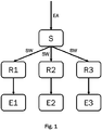
- FIG. 1 shows a schematic structure of a control device S for controlling a power supply system according to a first embodiment.
- the energy supply system is preferably a multivalent energy supply system, the energy generators E1-E3 of which use at least two different energy sources.
- the energy supply system shown has three energy generators E1-E3, which provide energy in the form of heat F1 and / or cold F3 and / or electrical energy F2.
- the energy supply system has a control device S which is designed to detect at least one energy supply request EA for providing energy in the form of heat F1 and / or cold F3 and / or electrical energy F2.
- the at least one energy supply request EA can be generated, for example, by a large number of consumers (not shown), specified manually by a user, or generated by a higher-level device that communicates with the control device.
- the control device S determines setpoints for the plurality of energy generators E1-E3 of the energy supply system as a function of the at least one energy supply request EA and outputs the setpoints SW to control devices R1-R3 of the energy generators E1-E3.
- Embodiment of the energy supply system shown comprises three energy generators E1-E3, the invention is not limited to the fact that the energy supply system has only three energy generators E1-E3. Rather, any number of energy generators can be controlled by a control device S according to the invention or using one of the methods according to the invention.
- the control device S is designed for each energy form F1-F3 to determine which energy generators E1-E3 are required to meet the at least one energy supply requirement EA. The determination can be carried out as a function of the amount of energy requested by the at least one energy supply request EA and the power that can be provided by the energy generators E1-E3.
- control device S For each form of energy F1-F3, the control device S generates switch-on requests ON for the energy generators E1-E3 required to fulfill the at least one energy supply request EA. Furthermore, the control device S generates switch-off requests AUS for each energy form F1-F3 for the energy generators E1-E3 which are not required to fulfill the at least one energy supply request EA.
- control device S determines whether there is one, several or no switch-on request ON and whether there is one, several or no switch-off request OFF.
- the control device S In a first operating mode "ON before OFF", the control device S issues a switch-on request ON for each energy generator E1-E3 for which there is at least one switch-on request ON to the corresponding control device R1-R3. For each energy generator E1-E3 for which there is no switch-on request ON and at least one switch-off request OFF, the control device S issues a switch-off request OFF to the corresponding control device R1-R3.
- the control device S issues an OFF request for each energy generator E1-E3 for which there is at least one switch-on request OFF to the corresponding control device R1-R3.
- the control device S issues a switch-on request ON to the corresponding control device R1-R3.
- the control device S sets a priority for each energy form F1-F3, so that each energy form F1-F3 receives a different priority. For example, heat F1 can receive the highest, electrical current F2 a medium and cold F3 the lowest priority.
- heat F1 can receive the highest, electrical current F2 a medium and cold F3 the lowest priority.
- the control device S outputs the switch-on request ON or switch-off request OFF, which was generated by the energy form F1-F3 with the higher priority, to the corresponding control device R1-R3.
- a switch-off request AUS is output to the control device R1 in accordance with the exemplary priority division.
- the control device S is also designed to determine setpoints SW for each energy generator E1-E3 in order to fulfill the at least one energy supply request EA depending on the determined switch-on request (s) ON and / or switch-off request (s) OFF and the setpoints SW to the control devices R1 -R3 output.
- control device S If the control device S detects energy supply requests EA for the simultaneous provision of heat F1 and electrical current F2, the control device S can determine a first energy generator designed for the simultaneous provision of the first energy form heat F1 and the second energy form electrical current F2, for example the aforementioned CHP plant E1.
- the control device S determines that for a second energy generator E2, which is designed to provide heat F1, for example a gas boiler E2, there is a switch-on requirement ON of the first energy form F1.
- the control device S recognizes that the CHP E1 can meet the energy supply requirement EA for both heat F1 and electrical current F2 and is already switched on for the provision of electrical current. Switching on the gas boiler E2 can be avoided here. Therefore, the control device S generates a switch-on request ON of the first energy form heat F1 for the CHP E1 and a switch-off request OFF of the first energy form heat F1 for the gas boiler E2 and outputs these switching requests to the corresponding control devices R1-R2. The CHP E1 then provides the requested energy in the form of heat F1 and electrical current F2. The gas boiler E2 does not have to be switched on at all.
- the control device S preferably executes the control method according to the invention periodically at predetermined discrete times k.
- the control device determines a first energy generator E1, which is designed to simultaneously provide a first energy form heat F1 and a second energy form electrical current F2.
- This can in turn be the CHP E1 of the example described above.
- the CHP E1 was due to the activation requirement of the second energy form F2 in operation.
- the CHP E1 had the status "requested externally".
- the control device has generated a switch-off request AUS to the CHP E1 for the second energy form F2. If there is also a switch-off request OFF from the first energy form heat F1, the CHP plant E1 would be switched off since there would now be a switch-off request OFF for both energy forms heat F1 and electrical current F2, which the CHP plant E1 can provide.
- the control device S can recognize that it is advantageous to generate a switch-on request ON for the CHP E1 for the energy form F1.
- the CHP E1 is already in operation because of a previously generated switch-on request of energy form F2 and does not have to be switched on first. A switching process for the CHP E1 could thus be avoided.
- This transfer of the CHP plant E1 from the energy form heat F1 can in particular also take place if the CHP plant E1 would not have had a turn in a switching sequence of the energy form heat F1, but a second energy generator, for example the gas boiler E2. Switching off the CHP E1 and switching on the gas boiler E2 can thus be prevented.
- a switch-on indicator for the energy generator E1 is another energy generator E2-E3, which is also given a switch-on request ON for the same form of energy. In the present example, this can be the gas boiler E2, which can also provide heat F1. If, for the gas boiler E2 at the previous point in time k-1, there was a switch-off request OFF from the first energy form heat F1 and now at the current point in time k a switch-on request ON is issued by the first energy form heat F1, the switch-on request ON is described as above CHP E1 transferred.
- the generated switch-on request EIN to the gas boiler E2 is an indicator that more heat F1 is to be provided. Therefore, the gas boiler E2 is referred to here as the switch-on indicator for the CHP E1.
- the control device S can detect or even determine an order of switching on and / or switching off the energy generators E1-E3 for each energy form F1-F3.
- the switch-on requests ON and / or switch-off requests OFF are then determined depending on the sequence.
- the control device S can also decide that energy generators E1-E3 are skipped in the sequence if a switching process can be avoided as a result.
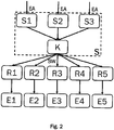
- FIG. 2 shows a second embodiment of an energy supply system with five energy generators E1-E5. Only differences between the second exemplary embodiment and the first exemplary embodiment are described in more detail below.
- the control device S here comprises three control units S1-S3 and a coordinating unit K.
- the control units S1-S3 each record an energy supply request EA for each energy form F1-F3.
- the first control unit S1 can record an energy supply request EA in the form of a heat request
- the second control unit S2 can record an energy supply request EA in the form of a request for supplying electrical energy
- the third control unit S3 can record an energy supply request EA in the form of a cooling request. Since there may be energy producers E1-E5 in the power supply system that provide more than one form of energy F1-F2, such as a combined heat and power plant that provides electrical energy F2 and heat F1, the control device S may have energy supply requirements EA for different forms of energy F1-F3 recorded that affect the same energy producer E1-E5.
- the coordination unit K is designed to check the energy supply requirements EA detected by the three control units S1-S3 and the target values determined therefrom for conflicts and to coordinate the use of the energy generators E1-E5 accordingly. For this purpose, different priorities can be given to the individual forms of energy F1-F3, for example. For example, in an energy supply system with one or more CHP units, it would make sense to give priority to requests for the provision of electrical energy F2 so that the CHP units are not switched off if (temporarily) there is no request to provide heat F1 and therefore generates a switch-off request for heat F1 becomes.
- the coordination unit K is designed to regulate the interaction between the various forms of energy F1-F3.
- Energy generators E1-E5, which provide several forms of energy F1-F3 and receive a switch-on request ON with respect to a first form of energy F1-F3, for example electricity F2, are intended, for example, on the basis of energy supply requirements EA for a second form of energy F1-F3, for example heat F1 or third Energy form F1-F3, for example cold F3, cannot be switched off.
- the coordination unit K assigns priorities to the forms of energy. The order of priorities can be fixed or variable.
- that form of energy F1-F3 that first gives an energy generator E1-E5 a request to switch on can receive the highest priority.
- the energy form F1-F3 can do this keep the top priority for a long time as their demand is. If several energy forms F1-F3 issue a switching request to an energy generator E1-E5 in a calculation step k, the priority can also be determined in accordance with a predetermined sequence of priorities.
- the coordination unit K can also take into account that as few switching operations as possible should take place.
- the coordination unit K also takes into account generator-specific specifications, since there are energy generators E1-E5 which must not be switched for a specific time after being switched on or off. Other energy generators E1-E5 can be switched on and off practically indefinitely.
- FIG 3 shows a schematic representation of a third embodiment of an energy supply system for providing heat F1 and electrical energy F2.
- a hydraulic diagram (a schematic representation of the infrastructure) of the energy supply system is shown for the heat supply, in which heat is given off to a fluid carrier medium, for example water.
- the carrier medium transports the heat via a lead V to at least one consumer circuit (not shown).
- the flow V is shown as a solid arrow, which illustrates the direction of flow of the carrier medium to the consumer circuit.
- a large number of consumers for example a large number of radiators, can be arranged in the consumer circuit.
- the carrier medium flows from the consumer circuit back to the energy supply system via a return R.
- the return R is shown as a dashed arrow, which illustrates the direction of flow of the carrier medium.
- the carrier medium can be made to flow, for example, by means of circulation pumps, which can be arranged in the generator circuit, for example in the energy generators B1-B2, G1-G2 and / or in the consumer circuit.
- valves and / or throttle valves and / or sensors for measuring the current and / or the temperature in the energy generators B1-B2, G1-G2 and / or in the flow V and / or in the return R can be arranged to flow through the To control or regulate energy generators B1-B2, G1-G2.
- the energy supply system has two combined heat and power plants (CHP) B1-B2 and two gas boilers G1-G2, the two CHP plants B1-B2 being arranged parallel to each other between flow V and return R. Via the return R, the carrier medium coming from the consumers flows to the energy generators, which supply heat to the carrier medium. The carrier medium flows to the consumer circuit via the flow V.
- the BHKW B1-B2 are for this designed to provide energy in the form of heat F1 and electrical current F2.
- the two gas boilers G1-G2 are designed to provide energy in the form of heat F1.
- a first gas boiler G1 is also arranged parallel to the CHP plants B1-B2 and downstream of them at the flow V.
- the first gas boiler G1 is, for example, a condensing boiler with a high degree of efficiency.
- a further gas boiler G2 is arranged in series in the flow V further downstream of the buffer store P, so that the second gas boiler G2 can raise the flow temperature directly. Due to the arrangement of the second gas boiler G2 in the flow after the buffer store, it cannot influence the temperature of the water stored in the buffer store.
- the second gas boiler G2 is in particular a gas boiler that can still operate even when the temperature of the carrier medium is already relatively high.
- the CHP plants B1-B2 and the gas boilers G1-G2 each have a control device R1-R4 for controlling control variables of the energy generators B1-B2, G1-G2.
- a control device S is connected to the control devices R1-R4 and can periodically poll the set control variables from the control devices R1-R4 at predetermined discrete times k and / or output setpoint values SW as well as switch-on requests ON and switch-off requests OFF to the control devices R1-R4.
- the energy supply system can thus be similar to that in Figure 1 shown, but with four energy generators B1-B2, G1-G2.
- the control device S can receive energy supply requests EA, that is, requests for the provision of electrical energy F2 and / or heat F1, for example from the consumer circuit or a higher-level consumption controller.
- the control device S controls the energy generators B1-B2, G1-G2 via the control devices R1-R4 in order to meet the required energy requirement.
- the energy supply system of the present example is to be operated according to the following task:
- the CHP plants B1-B2 should preferably be used so that electrical energy F2 can be provided at any time in addition to heat F1.
- the operation of CHP plants is particularly reliable due to the long and uninterrupted running times and by avoiding switching operations, the energy generators B1-B2, G1-G2 can be spared.
- the first gas boiler G1 should only be used if both CHP plants B1-B2 are already in operation and the heat they provide in the flow V is not sufficient to meet an energy supply request EA, for example in the form of a required temperature in the buffer storage P or a system flow temperature at the handover to the consumer cycle (far right in Figure 3 ) to meet.
- the gas boiler G1 can already be switched on when one of the two CHP plants B1-B2 is already in operation in order to be able to react particularly quickly to a temporarily increased heat requirement.
- the second gas boiler G2 should only be switched on when both CHP plants B1-B2 and the first gas boiler G1 are already in operation and the heat provided is not sufficient to supply a requested flow temperature.
- the sequence in which the gas boilers G1 and G2 are switched on should be fixed, since the gas boiler G1 is a condensing boiler with a high degree of efficiency.
- the CHP plants B1 and B2 should also be able to be switched on if there is an energy supply request EA for electrical energy.
- a runtime compensation should take place between the two CHP plants B1-B2.
- a requirement for the control system is that a runtime compensation should take place between the CHP plants B1-B2.
- a fixed sequence of switching on and / or switching off with the CHP B1-B2 would have to be defined in the first two places in a control according to the prior art. With a fixed sequence of switching on and / or switching off, however, no runtime compensation would be possible. With a conventional control system, the first CHP unit B1 would receive considerably more operating hours than the second CHP unit B2.
- the two CHP plants B1-B2 are assigned to a first group GR1.
- CHP units B1-B2 can swap jobs within group GR1.
- a criterion for where a CHP unit should be in the group can be the runtime difference between the CHP units B1-B2.
- a minimum runtime difference can be specified, from which the positions should be exchanged.
- the control device records the running times of the CHP plants B1-B2 and determines the sequence of the CHP plants B1-B2 depending on the recorded running times.
- Job-specific criteria are criteria for switching energy producers on or off, which are retained in their respective positions in a group and do not exchange with the energy producers when the positions within the group are exchanged.
- a job-specific criterion can be, for example, guidelines as to how an energy generator should be switched on and off in time. These can be, for example, a switch-on integral and / or a switch-off integral.
- Another example of a job criterion is the switching off of an energy generator as a function of a buffer temperature.
- a behavior of the energy supply system can be defined that is independent of which energy generator is currently in the corresponding position.
- threshold values can be defined, which exceed or fall below a certain predetermined switching behavior. For example, it can be determined for each point in the order of the energy producers whether the energy generator should be switched off or on at the respective point if a threshold value is exceeded or not reached. It is thus possible to predefine the behavior of an energy supply system with a configuration that may still be unknown, regardless of the energy generators actually used later, within certain limits.
- the order in which the first gas boiler G1 and the second gas boiler G2 are switched on should be fixed. A runtime compensation between the gas boilers G1-G2 should not take place. To achieve this, the two gas boilers G1-G2 are assigned to two separate groups GR2, GR3.
- the three groups GR1-GR3 of the first energy form F1 can be assigned to a common cascade 1.
- a cascade is therefore a higher level than the groups in the division of energy producers.
- the order of the groups GR1-GR3 is usually fixed and is not changed by the control device S. However, it can also be provided that the order of the groups changes under certain circumstances.
- group GR1 is placed first in cascade 1. Since the gas boiler G1 should preferably be operated, the group GR2 is placed in second place. In the present exemplary embodiment, the order of the group is thus fixed.
- the CHP plants B1-B2 can be operated as follows to provide heat:
- the first CHP plant B1 in the first place in the GR1 group (depending on the runtime compensation, this can also be the second CHP plant B2) will fall below a required one Plant flow temperature switched on.
- the required system flow temperature is measured downstream of the second gas boiler G2 in the flow V. If a predetermined limit value of the temperature in the buffer store P, which is measured in a layer lying below in the buffer store P, is exceeded, the first CHP unit B1 is switched off.
- the control of the second CHP unit B2 in second place in group GR1 is carried out in a similar manner to that of the first CHP unit B1. If, despite the CHP B1 being switched on, a drop below the required system flow temperature is detected, the control device S switches on the second CHP B2. If a predetermined limit value of the temperature in the buffer store P, which is measured, for example, in a layer located in the middle of the buffer store P, is exceeded, the control device S switches the second CHP unit B2 off again.
- the gas boiler G1 is switched on when the CHP plants B1 and B2 are already switched on when the required system flow temperature is undershot.
- the gas boiler G1 is switched off when a threshold value of the temperature in the buffer store P, which is measured in an upper layer, is exceeded.
- the second gas boiler G2 is switched on. As soon as the required system flow temperature is exceeded, the control device S switches the gas boiler G2 off again.
- the control device S In addition to the energy supply requests EA for heat F1, the control device S also receives energy supply requests EA for electrical energy F2 or electrical power (for example in the form of a current request or a voltage request).
- the CHP plants B1-B2 can therefore be switched or regulated in addition to an energy supply request EA for heat F1 as a function of an energy supply request EA for electrical energy F2. Therefore, the CHP plants B1-B2 are assigned to a second form of energy F2 for electrical energy.
- Energy supply requirements EA for electrical energy F2 and / or switching requirements (ON / OFF) for energy producers that provide electrical energy F1 are generated or taken into account by the control device S.
- the BHKW B1-B2 can thus be used to meet the energy supply requirements EA of two forms of energy F1-F2.
- contradicting claims are received (or generated) by the control device S. So it may be that the energy form heat F1 requires that both CHP plants B1-B2 should be switched off because, for example, the buffer store P has reached its maximum temperature.
- the energy form electrical energy F2 continues to request the operation of the first CHP.
- the control device S must therefore decide which requirement from which form of energy F1-F2 should be given priority.
- the energy supply requests EA for heat F1 and for electrical energy F2 are processed in a coordinated manner by the control device S. This corresponds to a compromise finding between the energy supply request for heat F1 and the energy supply request for electrical energy F2. If the energy form heat F1 requires, for example, a switch-off of a CHP unit B1-B2, the control device S first checks whether operation of the CHP unit B1-B2 is still required in order to fulfill an energy supply requirement for electrical energy F1-F2 before the CHP unit B1 in question -B2 is switched off.
- a switch-on request ON is always given priority ("ON before OFF”). Accordingly, an energy generator remains switched on whenever at least one form of energy F1-F3 requests the relevant energy generator. The energy generator is only switched off when no form of energy F1-F3 requests the operation of the energy generator.
- Alternative strategies can provide that a switch-off request OFF is always given priority ("OFF before ON") or a prioritization of the energy forms F1-F3 is defined, so that the control device S always follows a switching request ON / OFF of a specific energy form F1-F3 .
- a modification of the third exemplary embodiment is described below in which the following tasks are to be fulfilled: Requirements for electrical energy F2 are to be covered by the CHP plants B1-B2. Furthermore, power blocks specified by the consumers should be taken into account when operating the CHP plants B1-B2. A current block here specifies a requirement that no electrical energy may be fed into the local network from the energy supply system. In the event of power blocks, the gas boilers G1-G2 alone have to provide heat.
- the CHP plants B1-B2 should preferably be used. As a result, the operation of the energy supply system can be particularly reliable. As long as there is no power cut, the CHP units B1-B2 become Providing heat is used, whereby the CHP plants B1-B2 can be used particularly efficiently while simultaneously providing electrical energy.
- the number of times the CHP B1-B2 is switched on and off due to changing requirements for electrical energy F2 and / or heat F1 should be reduced as far as possible. This is intended to protect the CHP plants B1-B2 and to achieve particularly uninterrupted and reliable continuous operation.
- a first mode of operation requirements for the provision of electrical energy act directly on the CHP B1-B2 and are therefore automatically prioritized over requirements for the provision of heat.
- This mode of operation can result in a very limited control quality.
- control device only takes into account requirements for providing heat.
- the electrical energy generated by the BHKW B1-B2 is only a by-product and can therefore not be adapted to the needs. Power locks are ignored in this mode.
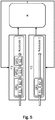
- FIG. 5 shows a fourth embodiment, in which the control device S comprises as a further component a coordination unit K, which is designed to coordinate energy supply requirements EA for heat F1 and electrical energy F2.
- the control device S can be similar to that described in the second exemplary embodiment and in Figure 2 shown for each form of energy F1-F2 comprise an assigned control unit S1-S2, the coordination unit K comparing and coordinating the setpoint values SW generated by the control units S1-S2 with each other before being output to the relevant control devices R1-R4.
- Coordinating means, in particular, that conflicts between switch-on and switch-off requests from different forms of energy F1-F2 are resolved and that avoidable switching operations are recognized.
- the method carried out by the control device S with the coordination unit K can, for example, proceed as follows:
- the control device S checks whether the CHP unit B1, which is operated on the basis of an energy supply request EA for supplying electrical energy F2, is sufficient to meet an energy supply request EA for supplying heat F1 would.
- the control device S makes an estimate of the power required to meet the energy supply requirement EA for providing heat F1. If the previously recorded energy supply request EA for supplying electrical energy F2 no longer applies - if a switch-off request OFF is generated for the energy form F2 (in particular by the control device S itself), the coordinating unit K can decide to continue to supply the CHP unit B1 with heat F1 operate (takeover of the CHP plant B1 by the energy form F1).
- the control device S generates a switch-on request ON for the energy form heat F1.
- the transition of the switch-on requirement ON from the energy form electrical energy F2 to the energy form heat F1 is also referred to as external transfer.
- the CHP unit B1 remains switched on continuously due to the delay-free change of the switch-on request ON for providing electrical energy F2 to the switch-on request ON for providing heat F1 and now continues to supply the heat which is required to maintain the heat requirement. In this way, a switching process of switching the CHP B1 off and on again can be avoided.
- the control quality for the provision of heat remains consistently high and the service life of the BHKW B1 can be improved.
- the controlled operation of the energy supply system (for a first form of energy F1, a switch-on request ON is recorded, changes to a switch request to provide a further form of energy F2 are considered to be interference) accepted) regulated operation of the system.
- the calculated switching requests ON / OFF are returned to the respective other form of energy via the coordination unit K, so that changes in the switching requests can be taken into account immediately and in a coordinated manner.
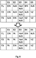
- FIG. 6 shows a hydraulic diagram of a power supply system according to a fifth embodiment.
- the energy supply system comprises two gas boilers G1-G2, two BKHW B1-B2 and two wood boilers H1-H2 as well as a buffer storage P.
- a temperature sensor T1 is arranged in the flow V, which measures the system flow temperature.
- Three temperature sensors T2-T4 are arranged in the buffer store P, each measuring the temperature in the buffer store P, respectively in an upper area, in a middle area and in a lower area of the buffer store.
- the temperature sensors T1-T4 output their measurement signals to a control device S.
- the energy supply system is controlled as a function of a detected energy supply requirement EA, which, for example, specifies a required system flow temperature, for example at measuring point T1, or a buffer storage temperature at one of the three measuring points T2-T4 of buffer storage P.
- the control device S can then determine target values SW for the energy generators B1-B2, G1-G2, H1-H2 as a function of a deviation of the values measured at the measurement points T1-T4 from the specifications of the energy supply request EA and output them to the corresponding control devices.
- the two wooden boilers H1-H2 are assigned to a group GR1. As described above, a runtime compensation can take place in the group between the wooden boilers H1-H2.
- the two CHP plants B1-B2 are assigned to group GR2 and also operated with runtime compensation.
- the two gas boilers G1 and G2 are assigned to group GR3.
- a runtime compensation can also take place between the gas boilers G1-G2. This division of the energy producers into groups takes place within the energy form heat F1.
- the two CHP plants B1-B2 are also divided into groups (or a group) within the energy form electrical energy F2.
- the wood boilers H1-H2 and the CHP plants B1-B2 are classified as preferred energy producers because their operation has economic advantages compared to the gas boilers G1-G2.
- the groups GR1 and GR2 are assigned to a first cascade 1.
- the order of groups GR1 and GR2 within the group can be based on group-specific criteria. For example, the sequence can be determined depending on the current fuel costs or the availability of the energy sources used, depending on planned maintenance measures or made dependent on an energy supply requirement for electrical energy F2.
- producer-specific criteria can influence the order of the groups GR1, GR2 in cascade 1.
- a requirement for the control device S can be that a large amount of energy is to be stored in the buffer store P.
- a buffer temperature sensor T4 is selected in a lower area of the buffer memory P for the buffer temperature control.
- the target buffer temperature is set to 70 ° C, for example.
- the control device S then ensures that the buffer store P is fully charged to a temperature of 70 ° C.
- a buffer temperature sensor T3 is selected in a central region of the buffer store P for the buffer temperature control.
- a buffer temperature sensor T2 is selected at an upper area of the buffer memory P for the buffer temperature control. It is not necessary to specify a target buffer temperature, since a target energy generator supply temperature can be calculated from a target system supply temperature. Only as much energy is generated as is consumed by the consumers, the buffer store P is not loaded in this case.
- the system flow temperature can be measured, for example, by a temperature sensor T1 on the flow V.
- Figure 7 illustrates the division of the energy generators of the seventh embodiment into groups and cascades.
- an exemplary system status is displayed, in which the two wood boilers H1-H2 of the first group GR1 are both switched on and running under full load.
- the two CHP plants B1-B2 of the second group GR2 are switched off.
- the first gas boiler G1 is switched on and is operated in a modulating manner with a load of currently 40%.
- the mode of operation of the method according to the invention is to be described in detail in a sixth exemplary embodiment.
- the aim of the process is to minimize the switch-on and switch-off processes of energy producers as much as possible. In other words, one aim of the method is to avoid producer cycles.
- a lock is issued to an energy producer, or if there is a producer-specific criterion that prevents an energy producer from being switched on, this fact is taken into account by the control device S when generating switch-on requests ON.
- the affected energy producer is ignored for the duration of the lock when controlling the energy supply system.
- a blocked energy generator is skipped when the sequence is processed. This prevents the control from getting stuck on the blocked energy generator and from being able to optimally meet an energy supply request EA.
- the control device controls the energy producers in dependence on the energy form (s) F1-F3 provided by them.
- the energy producers are assigned to the energy forms F1-F3, that they can provide.
- the control device S determines which energy producers are requested to switch ON more than one energy form F1-F3, or the control device determines for each energy form F1- requested by the present energy supply request (s) EA. F3 which of the available energy producers are required to meet the energy supply requirement (s) EA.
- the control device generates switch-on requests ON for the energy generators required to fulfill the energy supply request (s) EA and preferably also switch-off requests OFF for the energy generators not required to fulfill the energy supply request (s) EA.
- the control device can determine the switch-on requests ON and switch-off requests OFF as an example (see Figure 8 ), which is described in more detail below.
- the demands of the different forms of energy can be summarized in a demand matrix.
- the top matrix in Figure 8 is an example of a demand matrix for five energy producers E1-E5 and three energy forms F1-F3.
- the energy generators E1-E5 are in the columns and the energy forms F1-F3 in the rows.
- An entry in the matrix can include a switch-on request (ON), a switch-off request (OFF), an indication that the energy producer E1-E5 does not offer the relevant form of energy F1-F3 ("not applicable", NZ) or a block ("hard OFF" ) of the energy generator E1-E5.
- the matrix thus contains all information about the requirements of the individual forms of energy F1-F3 for the individual energy suppliers E1-E5.
- the energy generator E3 is currently being serviced and can therefore not be used. There is a "hard OFF" in the claims matrix. Energy generator E1 receives an ON request from energy forms F1 and F2 and an OFF request from F3. Energy producer E4 can only provide energy forms F1 and F2, energy generator E5 only energy form F1.
- the interaction between the energy forms F1-F3 is regulated via the requirements matrix.
- the control device S can preferably have a coordination unit K, which is designed to coordinate the demands of the individual forms of energy F1-F3 on the energy producers E1-E5.
- the strategy can be followed that energy producers E1-E5, which can provide more than one energy form F1-F3 and have received an ON request for an energy form F1-F3, are no longer switched off by other energy forms F1-F3 can. This can be done, for example, using the "ON ahead” or "OFF before ON” rules already described. Alternatively, the forms of energy F1-F3 can be prioritized. The highest priority form of energy F1-F3, which gives an energy generator E1-E5 a switch-on request ON, becomes the so-called master via the energy generator E1-E5.
- a so-called external requirement matrix (FA matrix for short) can be determined from the requirement matrix.
- the FA matrix receives information for each energy form F1-F3 and each energy generator E1-E5 as to whether the corresponding energy generator E1-E5 has received an ON request from an energy form F1-F3 with a higher priority (master).
- the switch-on request ON of the master energy form F1-F3 is also referred to as an external request (FA) with respect to the energy form F1-F3 with a lower priority.
- the FA matrix can have one or more "FA” entries. As long as an energy generator E1-E5 has an entry "FA" for an energy form F1-F3 in the FA matrix, it can no longer be switched off by this energy form F1-F3.
- Figure 8 illustrates how an external requirements matrix (bottom) is created from the requirements matrix (top).
- first energy generator E1 there is an ON request for the first energy form F1 and the second energy form F2.
- the third energy form F3 delivers an OFF request. If there are two ON switch-on requests, it must be decided which of the energy forms F1-F2 should take over the energy generator E1 as the master.
- an energy form F1-F3 can, for example, be defined as a master via an energy generator E1-E5 if it has first given the relevant energy generator E1-E5 a switch-on request ON.
- the energy form F1-F3 can remain master until it withdraws its switch-on request ON or is replaced by a switch-off request OFF. If two forms of energy F1-F3 simultaneously give a power-on request E1-E5 a switch-on request ON, a predetermined priority sequence of the forms of energy F1-F3 can be used, for example.
- a CHP such as in a power supply system of the fifth exemplary embodiment, it would make sense to assign the highest priority to the energy form electrical energy F2, since the energy form heat F1 drops as a by-product.
- Third-party energy producers E1-E5 remain switched on and make a contribution to covering the energy requirements for all energy types F1-F3 concerned. If an energy generator E1-E5 is no longer requested by the first energy form F1-F3 (master), the energy generator can be taken over by a second energy form F1-F3, in which it was considered to be requested externally (FA), if the energy generator E1- E5 is required to meet the energy supply requirement EA of the second energy form F1-F3. For this purpose, the control device S can make an estimate of the expected energy requirement.
- the second energy form F1-F3 gives the relevant energy producer E1-E5 a switch-on request ON.
- the second form of energy F1-F3 becomes the master of the relevant energy generator E1-E5. This can prevent the energy generator E1-E5 from being switched off first and then being switched on again by a switch-on request ON for the second energy form F1-F3.
- control device S can be designed to determine an expected energy requirement. Furthermore, the control device S can be designed to estimate whether the need can be covered by the released energy producers E1-E5, whereby all energy producers E1-E5 of the second energy form F1-F3 can make a contribution.
- So-called indicators can be considered in order to determine the energy requirement of a specific form of energy F1-F3. Individual indicators are assigned to each externally requested FA energy generator E1-E5, one indicator being a further energy generator E1-E5 of the relevant energy form F1-F3. As soon as an indicator receives a change in demand (from ON to OFF or from OFF to ON), it can be assumed that in the relevant energy form F1-F3 either too much (ON to OFF) or too little (OFF to ON) energy is provided becomes. If an indicator receives an ON request after it was previously switched off (OFF to ON), this is an indication that the energy producers E1-E5 of the relevant energy form F1-F3 provide too little energy.
- the result of the determination of the energy requirement is that the previously externally requested FA energy generator E1-E5 continues to be operated by the energy form F1-F3, that is to say is accordingly given a switch-on request ON by the energy form F1-F3.
- an indicator is switched off (OFF to ON)
- this indicates an excess supply of energy of the energy form F1-F3, so that the previously externally requested FA energy generator E1-E5 is not accepted and receives an OFF request.
- Indicators are preferably switchable (or controllable) energy generators E1-E5 within an energy form F1-F3.
- the energy generators E1-E5 are switched according to a defined sequence for switching on and / or switching off.
- Issuing a switch-on request (OFF to ON) to a switch-on indicator means that an initially externally requested FA energy generator E1-E5 within the considered energy form F1-F3 is taken over by the energy form F1-F3, i.e. that the energy form F1-F3 receives a switch-on request A issued.
- Issuing a switch-off request (ON to OFF) of a switch-off indicator means that an externally requested energy generator E1-E5 is not taken over by the energy form F1-F3. This method is described in more detail
- the externally requested FA energy generators E1-E5 are not taken over.
- a low cycle reduction is achieved if the externally requested FA energy generators E1-E5 are taken over according to a sequence of switching on and / or switching off.
- the control device S must therefore perform a calculation of the expected energy requirement.
- a high cycle reduction can be achieved by directly taking over all externally requested FA energy generators E1-E5 depending on the next switchable energy generator E1-E5 within the sequence of switching on.
- the mode in which the control device S is to operate can either be determined manually by a user, determined by a higher-level device, or determined by the control device S itself on the basis of parameters (for example depending on the season and / or an outside temperature). If the "no clock reduction" mode is selected, the externally requested energy generators E1-E5 are not taken over. This means that energy generators E1-E5 requested externally by a first energy form F1-F3 are no longer taken into account by the other energy forms F1-F3. For example, a first energy generator E1 is first given an OFF request from a first energy form F1. A second form of energy F2, however, requires this energy generator E1 to cover the energy requirement and gives the energy generator E1 a switch-on request.
- energy generators E1-E5 can be taken over by energy formers F1-F3 as required. According to need means that the transfer takes place depending on the expected energy requirement, in particular calculated by the control device S. In addition, the takeover can also be canceled if the need changes.
- This mode also takes into account a predetermined sequence for switching on and / or switching off the energy generators E1-E5 within the energy form F1-F3 for each energy form F1-F3. This means that the energy generators are normally only switched on or off along the sequence of switching on and / or switching off.
- Figure 9 shows eight energy generators E1-E8 of a first energy form F1, which are arranged in a first sequence of switching on and / or switching off (cascade 1). Furthermore, there may be further cascades with sequences of switching on and / or switching off that can be carried out independently of the first cascade 1.
- the switch-on requests ON and / or switch-off requests OFF of the first energy form F1 are shown in each case among the energy generators E1-E8.
- Energy generators E1 and E8 have a switch-on requirement ON given by energy form F1.
- the remaining energy generators E2-E7 have switch-off requests OFF, energy generator E5 having a lock hard OFF, so that it cannot be switched on.
- Energy producers E2, E4 and E7 which have been given a switch-off request from energy form F1, are requested by other energy forms in each case by switching-on requests ON. The following describes the conditions under which one of the externally requested energy generators E2, E4 and E7 can be taken over by energy form F1.
- energy generator E3 is the first switchable energy generator along the sequence of switching on in cascade 1 of energy form F1.
- energy generator E3 precedes all externally requested energy generators E2, E4, E7 in the sequence of switching on (from left to right), it cannot be in the "low clock reduction" mode for any of these energy generators E2, E4, E7 switch-on indicator. In other words, switching on only E3 would not lead to the takeover of one of the energy generators E2, E4, E7 in the energy form F1.
- the two energy generators E2 and E4 are requested by a third party and have a switchable energy generator, namely energy generator E6, in the order in which they are switched on.
- E6 is the switch-on indicator for E2 and E4.
- the energy form F1 would therefore issue the energy producers E2 and E4 each with a switch-on request if, according to the order, they first give the energy generator E6 a switch-on request ON. Since the energy generator E6 in the present example is the Figure 9 However, in the order in which it is switched on is only after energy generator E3, energy generator E6 could only be switched on simultaneously with or after switching on energy generator E3.
- the control device S could decide, depending on a calculated energy requirement, that the switch-on indicator itself, i.e. energy generator E6, is not even switched on in spite of the switch-on request ON, and the switch-on request ON for E6 a switch-off request OFF is replaced. This is particularly the case when the calculated energy requirements can be met by the energy generators E2 and E4 taken over.
- the same basic idea also applies to the determination of the switch-off indicator.
- the takeover of an externally requested energy generator is withdrawn if the last energy generator that can be switched off receives an OFF request in the sequence after the externally requested energy generator considered (to the right of). If there is no other switchable energy generator in the sequence, the first switchable energy generator in front of (left) the energy generator under consideration is used as a switch-off indicator. Of all energy generators in question, the one that is determined as the switch-off indicator is the one that has the smallest distance along the sequence from the externally requested energy generator under consideration.
- the control device S can also implement a "high clock reduction" mode.
- this mode the assumption applies that an energy generator requested externally for a second energy form F2 is always required to cover an energy requirement of a first energy form F1 if any energy generator receives an ON request in a sequence of switching on the first energy form F1.
- the first switchable energy generator in a sequence of switching on within the first energy form F1 is therefore suitable as a switch-on indicator.
- the mode "high clock reduction” is based on the representation in Figure 10 explained in more detail.
- Figure 10 shows an example of determining the power-on indicator in the "high clock reduction” mode.
- the energy form F1 here has eight energy generators E1-E8. It is understood that the mode is similarly applicable to any other number of energy producers and is not limited to the exemplary number.
- the three energy producers E2, E4, E7 of the in Figure 10 are requested externally by a second form of energy F2.
- All externally requested energy generators E2, E4, E7 have the same switch-on indicator, namely energy generator E3, which is the first switchable energy generator in the sequence in which the first energy form F1 is switched on.
- energy generator E3 receives an ON request to provide energy of the first energy form F1 (dotted arrow from OFF to ON)
- all externally requested energy generators E2, E4, E7 are also given ON requests of the energy form F1 (dashed arrows).
- the "high clock reduction" mode works without a switch-off indicator. There is no provision for withdrawing the external requirements that have been taken over, since the energy producers E2, E4, E7 that are taken over are to be requested by means of switch-off criteria of their own energy type F1 after the external energy type F2 has withdrawn their claim.
- the adopted energy generators E2, E4, E7 are then treated in exactly the same way as any other energy generator in energy form F1 for which there is an ON request. In particular, an energy generator is only switched off when each energy form F1, F2 issues an OFF request to the energy generator in question.
- the transfer can take place on the basis of activation indicators or without an indicator.
- the switch-on indicator can be, in particular, the next switchable energy generator which, in the sequence in which it is switched on, stands (to the right of) the externally requested energy generator under consideration. Energy generators that are in front of (to the left of) the externally requested energy generator in question in the order in which they are switched on are not considered as switch-on indicators in this operating mode.
- the switch-off indicator is in particular that energy generator which, in the sequence in which it is switched on, is the last energy generator that can be switched off after (to the right of) the externally requested energy generator under consideration.
- the switch-off indicator has the smallest distance to the externally requested energy generator among all switch-off energy generators within the sequence of switching on or switching off. If not If there is an energy generator that meets these criteria, the first energy generator that is in front of (to the left of) the energy generator under consideration in the sequence of switching on or switching off is used as the switch-off indicator.
- control device S can be designed to carry out calculations for controlling the energy supply system periodically at predetermined times k.
- each calculation step k only one form of energy F1-F3 can be the so-called master for an energy generator.
- An energy form F1-F3 can remain master until it withdraws its demand.
- the highest-priority energy form F1-F3 can in particular become the master of the energy producer. This situation can occur in particular when a master energy form F1-F3 withdraws its ON switch-on request and other energy forms F1-F3 want to take over the energy generator. In this case, the energy generator is "inherited" from the subsequent energy form F1-F3.
Landscapes
- Engineering & Computer Science (AREA)
- Business, Economics & Management (AREA)
- Physics & Mathematics (AREA)
- Health & Medical Sciences (AREA)
- Economics (AREA)
- General Physics & Mathematics (AREA)
- Thermal Sciences (AREA)
- Chemical & Material Sciences (AREA)
- Combustion & Propulsion (AREA)
- Mechanical Engineering (AREA)
- General Engineering & Computer Science (AREA)
- Water Supply & Treatment (AREA)
- Public Health (AREA)
- General Health & Medical Sciences (AREA)
- Human Resources & Organizations (AREA)
- Marketing (AREA)
- Primary Health Care (AREA)
- Strategic Management (AREA)
- Tourism & Hospitality (AREA)
- General Business, Economics & Management (AREA)
- Power Engineering (AREA)
- Theoretical Computer Science (AREA)
- Automation & Control Theory (AREA)
- Supply And Distribution Of Alternating Current (AREA)
Priority Applications (1)
| Application Number | Priority Date | Filing Date | Title |
|---|---|---|---|
| PL20155672T PL3683760T3 (pl) | 2016-03-24 | 2017-03-23 | Sposób sterowania systemem dostaw energii |
Applications Claiming Priority (3)
| Application Number | Priority Date | Filing Date | Title |
|---|---|---|---|
| DE102016205036.2A DE102016205036B4 (de) | 2016-03-24 | 2016-03-24 | Verfahren zum Steuern einer Energieversorgungsanlage |
| PCT/EP2017/056927 WO2017162793A1 (fr) | 2016-03-24 | 2017-03-23 | Procédé de commande d'un système d'alimentation en énergie électrique |
| EP17713610.8A EP3433826B1 (fr) | 2016-03-24 | 2017-03-23 | Procédé de commande d'un système d'alimentation en énergie électrique |
Related Parent Applications (2)
| Application Number | Title | Priority Date | Filing Date |
|---|---|---|---|
| EP17713610.8A Division EP3433826B1 (fr) | 2016-03-24 | 2017-03-23 | Procédé de commande d'un système d'alimentation en énergie électrique |
| EP17713610.8A Division-Into EP3433826B1 (fr) | 2016-03-24 | 2017-03-23 | Procédé de commande d'un système d'alimentation en énergie électrique |
Publications (2)
| Publication Number | Publication Date |
|---|---|
| EP3683760A1 true EP3683760A1 (fr) | 2020-07-22 |
| EP3683760B1 EP3683760B1 (fr) | 2021-07-14 |
Family
ID=58413073
Family Applications (3)
| Application Number | Title | Priority Date | Filing Date |
|---|---|---|---|
| EP20155672.7A Active EP3683760B1 (fr) | 2016-03-24 | 2017-03-23 | Procédé de commande d'une installation d'alimentation en énergie |
| EP17713610.8A Active EP3433826B1 (fr) | 2016-03-24 | 2017-03-23 | Procédé de commande d'un système d'alimentation en énergie électrique |
| EP20155671.9A Active EP3683648B1 (fr) | 2016-03-24 | 2017-03-23 | Procédé de commande d'une installation d'alimentation en énergie |
Family Applications After (2)
| Application Number | Title | Priority Date | Filing Date |
|---|---|---|---|
| EP17713610.8A Active EP3433826B1 (fr) | 2016-03-24 | 2017-03-23 | Procédé de commande d'un système d'alimentation en énergie électrique |
| EP20155671.9A Active EP3683648B1 (fr) | 2016-03-24 | 2017-03-23 | Procédé de commande d'une installation d'alimentation en énergie |
Country Status (7)
| Country | Link |
|---|---|
| US (1) | US10699352B2 (fr) |
| EP (3) | EP3683760B1 (fr) |
| CA (1) | CA3018643C (fr) |
| DE (1) | DE102016205036B4 (fr) |
| PL (3) | PL3433826T3 (fr) |
| RU (1) | RU2739751C2 (fr) |
| WO (1) | WO2017162793A1 (fr) |
Families Citing this family (6)
| Publication number | Priority date | Publication date | Assignee | Title |
|---|---|---|---|---|
| DE102017008011A1 (de) * | 2017-08-25 | 2019-02-28 | BauDesign-Rems GmbH | Vorrichtung zur Energieversorgung von Gebäuden |
| CN108798898B (zh) * | 2018-04-20 | 2023-11-28 | 华电电力科学研究院有限公司 | 质子交换膜燃料电池与燃气轮机联合供应蒸汽和热水的系统及方法 |
| DE102020209071A1 (de) | 2020-07-20 | 2022-01-20 | Robert Bosch Gesellschaft mit beschränkter Haftung | Steuerungsvorrichtung für ein HVAC-System |
| US11728658B2 (en) * | 2020-12-18 | 2023-08-15 | Caterpillar Inc. | Hybrid power system control and operating strategy based on power system state vector calculation |
| EP4178059A1 (fr) * | 2021-11-09 | 2023-05-10 | Rohde & Schwarz GmbH & Co. KG | Alimentation et son procédé de fonctionnement |
| CN115854412B (zh) * | 2023-02-03 | 2023-10-20 | 华能济南黄台发电有限公司 | 一种城市电厂供热机组电锅炉系统 |
Citations (7)
| Publication number | Priority date | Publication date | Assignee | Title |
|---|---|---|---|---|
| EP1202425A2 (fr) | 2000-09-28 | 2002-05-02 | Siemens Aktiengesellschaft | Système et méthode de planification de l'alimentation d'énérgie et interface avec un système de gestion d'énérgie pour l'utilisation dans la planification de l'alimentation d'énérgie |
| WO2008091970A2 (fr) | 2007-01-26 | 2008-07-31 | Thermodynamic Process Control, Llc. | Commande de modulation d'un système de chauffage hydronique |
| WO2009141176A1 (fr) | 2008-05-23 | 2009-11-26 | Webasto Ag | Système de chauffage mobile |
| EP2144130A1 (fr) | 2007-04-11 | 2010-01-13 | Daikin Industries, Ltd. | Dispositif de gestion de groupes et système de gestion de groupes |
| EP2187136A2 (fr) | 2008-11-17 | 2010-05-19 | Olaf Brüning | Procédé de fonctionnement d'un système de transport d'énergie thermique sur un support fluide |
| US20110012427A1 (en) | 2009-07-15 | 2011-01-20 | Jason Craig | System And Method Of Controlling A Plurality of Energy Loads and Energy Supplies In A Coordinated Manner |
| US20110071690A1 (en) | 2010-07-02 | 2011-03-24 | David Sun | Methods that provide dispatchers in power grid control centers with a capability to manage changes |
Family Cites Families (9)
| Publication number | Priority date | Publication date | Assignee | Title |
|---|---|---|---|---|
| DE10348563B4 (de) | 2002-10-22 | 2014-01-09 | Fisher-Rosemount Systems, Inc. | Integration von Grafikdisplayelementen, Prozeßmodulen und Steuermodulen in Prozeßanlagen |
| US8065131B2 (en) | 2005-07-29 | 2011-11-22 | General Electric Company | Configurable system and method for power and process plant modeling |
| DE202006001553U1 (de) | 2006-02-01 | 2006-06-29 | Handwerkskammer Osnabrück-Emsland | Schulungsgerät |
| US7778806B2 (en) | 2006-03-29 | 2010-08-17 | Hitachi, Ltd | Method and apparatus for simulating microcomputer-based systems |
| DE102007061415A1 (de) | 2007-12-16 | 2009-07-23 | Viessmann Werke Gmbh & Co Kg | Heizungsanlage |
| DE102008063954B3 (de) | 2008-12-25 | 2010-07-22 | Mayer, Michael, Dipl.-Ing. | Verfahren zum Regeln mindestens einer dezentralen Energieversorgungsanlage nach zumindest ökologischen Zielvorgaben, die insbesondere die Minimierung von CO2-Emissionen umfassen, sowie nach dem Verfahren geregelte dezentrale Energieversorgungsanlage |
| RU2528627C2 (ru) * | 2012-12-25 | 2014-09-20 | Федеральное государственное бюджетное образовательное учреждение высшего профессионального образования "Пензенская государственная технологическая академия" | Многофункциональная гибридная альтернативная электростанция |
| US10175681B2 (en) * | 2014-05-01 | 2019-01-08 | Johnson Controls Technology Company | High level central plant optimization |
| US20170031962A1 (en) * | 2015-07-31 | 2017-02-02 | Johnson Controls Technology Company | Systems and methods for visualizing equipment utilization in a central plant |
-
2016
- 2016-03-24 DE DE102016205036.2A patent/DE102016205036B4/de not_active Expired - Fee Related
-
2017
- 2017-03-23 US US16/087,661 patent/US10699352B2/en active Active
- 2017-03-23 EP EP20155672.7A patent/EP3683760B1/fr active Active
- 2017-03-23 PL PL17713610T patent/PL3433826T3/pl unknown
- 2017-03-23 PL PL20155671T patent/PL3683648T3/pl unknown
- 2017-03-23 EP EP17713610.8A patent/EP3433826B1/fr active Active
- 2017-03-23 PL PL20155672T patent/PL3683760T3/pl unknown
- 2017-03-23 WO PCT/EP2017/056927 patent/WO2017162793A1/fr not_active Ceased
- 2017-03-23 EP EP20155671.9A patent/EP3683648B1/fr active Active
- 2017-03-23 CA CA3018643A patent/CA3018643C/fr active Active
- 2017-03-23 RU RU2018137207A patent/RU2739751C2/ru active
Patent Citations (7)
| Publication number | Priority date | Publication date | Assignee | Title |
|---|---|---|---|---|
| EP1202425A2 (fr) | 2000-09-28 | 2002-05-02 | Siemens Aktiengesellschaft | Système et méthode de planification de l'alimentation d'énérgie et interface avec un système de gestion d'énérgie pour l'utilisation dans la planification de l'alimentation d'énérgie |
| WO2008091970A2 (fr) | 2007-01-26 | 2008-07-31 | Thermodynamic Process Control, Llc. | Commande de modulation d'un système de chauffage hydronique |
| EP2144130A1 (fr) | 2007-04-11 | 2010-01-13 | Daikin Industries, Ltd. | Dispositif de gestion de groupes et système de gestion de groupes |
| WO2009141176A1 (fr) | 2008-05-23 | 2009-11-26 | Webasto Ag | Système de chauffage mobile |
| EP2187136A2 (fr) | 2008-11-17 | 2010-05-19 | Olaf Brüning | Procédé de fonctionnement d'un système de transport d'énergie thermique sur un support fluide |
| US20110012427A1 (en) | 2009-07-15 | 2011-01-20 | Jason Craig | System And Method Of Controlling A Plurality of Energy Loads and Energy Supplies In A Coordinated Manner |
| US20110071690A1 (en) | 2010-07-02 | 2011-03-24 | David Sun | Methods that provide dispatchers in power grid control centers with a capability to manage changes |
Also Published As
| Publication number | Publication date |
|---|---|
| EP3433826A1 (fr) | 2019-01-30 |
| RU2018137207A3 (fr) | 2020-06-30 |
| CA3018643A1 (fr) | 2017-09-28 |
| RU2739751C2 (ru) | 2020-12-28 |
| PL3433826T3 (pl) | 2021-03-08 |
| EP3683760B1 (fr) | 2021-07-14 |
| EP3683648A1 (fr) | 2020-07-22 |
| US10699352B2 (en) | 2020-06-30 |
| EP3433826B1 (fr) | 2020-09-02 |
| DE102016205036B4 (de) | 2018-12-13 |
| WO2017162793A1 (fr) | 2017-09-28 |
| EP3683648B1 (fr) | 2021-09-08 |
| US20190114724A1 (en) | 2019-04-18 |
| DE102016205036A1 (de) | 2017-09-28 |
| PL3683760T3 (pl) | 2021-12-20 |
| RU2018137207A (ru) | 2020-04-24 |
| CA3018643C (fr) | 2023-09-05 |
| PL3683648T3 (pl) | 2022-01-24 |
Similar Documents
| Publication | Publication Date | Title |
|---|---|---|
| EP3683648B1 (fr) | Procédé de commande d'une installation d'alimentation en énergie | |
| EP2918795B1 (fr) | Régulation pour systèmes de pile ORC | |
| DE102017220414A1 (de) | Verfahren zum Betreiben eines eine Wärmepumpe aufweisenden Wärmespeichersystems | |
| EP3433827B1 (fr) | Procédé de commande d'une installation de distribution d'énergie multivalente | |
| DE102015107214A1 (de) | Verfahren und Vorrichtung zur Steuerung der Wärmeversorgung von Wärmeverbrauchern | |
| EP2084801A1 (fr) | Procédé de fonctionnement d'un réseau à basse tension | |
| DE102013108879A1 (de) | Verfahren zum Betreiben eines Kraftwerkssystems | |
| EP3433824B1 (fr) | Procédé pour commander une installation d'alimentation en énergie polyvalente | |
| EP2875560A1 (fr) | Procédé de réglage du rapport entre l'énergie électrique injectée et prélevée dans un réseau d'alimentation en énergie électrique | |
| DE102012108496A1 (de) | Energiewandlervorrichtung und Verfahren zum Bereitstellen von Regelleistung | |
| EP3433825B1 (fr) | Procédé de commande d'un système d'alimentation en énergie électrique multivalent | |
| EP3139103B1 (fr) | Procédé de préparation de boissons chaudes | |
| DE102021006564A1 (de) | Verfahren zum betreiben eines heizungssystems mit brennstoffzelle und heizungssystem mit brennstoffzelle | |
| DE102021203798A1 (de) | Verfahren zum betreiben eines heizungssystems mit brennstoffzelle und heizungssystem mit brennstoffzelle | |
| EP3433684B1 (fr) | Dispositif et procédé de configuration d'une installation d'alimentation en énergie multivalente | |
| DE102009008649B4 (de) | Verfahren und Vorrichtung zum Regeln der Laufzeit eines Brenners | |
| DE102012212040B4 (de) | Wärmepumpenanlage sowie Verfahren zum Bereitstellen von Warmwasser | |
| DE102022101012A1 (de) | Regel- und Steuerungsverfahren sowie Anlage zur verringerten CO2-Emission | |
| WO2004059156A2 (fr) | Combinaison de dispositifs de couplage de force et de chaleur | |
| DE102017223549A1 (de) | Energiesystem und Verfahren zum Betrieb eines Energiesystems | |
| WO2019162029A1 (fr) | Système pour commander des flux d'énergie | |
| DE102012210063A1 (de) | Betrieb und Auslegung einer Anlage |
Legal Events
| Date | Code | Title | Description |
|---|---|---|---|
| PUAI | Public reference made under article 153(3) epc to a published international application that has entered the european phase |
Free format text: ORIGINAL CODE: 0009012 |
|
| STAA | Information on the status of an ep patent application or granted ep patent |
Free format text: STATUS: REQUEST FOR EXAMINATION WAS MADE |
|
| 17P | Request for examination filed |
Effective date: 20200205 |
|
| AC | Divisional application: reference to earlier application |
Ref document number: 3433826 Country of ref document: EP Kind code of ref document: P |
|
| AK | Designated contracting states |
Kind code of ref document: A1 Designated state(s): AL AT BE BG CH CY CZ DE DK EE ES FI FR GB GR HR HU IE IS IT LI LT LU LV MC MK MT NL NO PL PT RO RS SE SI SK SM TR |
|
| STAA | Information on the status of an ep patent application or granted ep patent |
Free format text: STATUS: EXAMINATION IS IN PROGRESS |
|
| 17Q | First examination report despatched |
Effective date: 20200731 |
|
| RBV | Designated contracting states (corrected) |
Designated state(s): AL AT BE BG CH CY CZ DE DK EE ES FI FR GB GR HR HU IE IS IT LI LT LU LV MC MK MT NL NO PL PT RO RS SE SI SK SM TR |
|
| RIC1 | Information provided on ipc code assigned before grant |
Ipc: F24H 9/20 20060101ALI20201203BHEP Ipc: G05D 23/19 20060101ALI20201203BHEP Ipc: H02J 3/14 20060101ALI20201203BHEP Ipc: G06Q 50/06 20120101AFI20201203BHEP Ipc: F24D 19/10 20060101ALI20201203BHEP |
|
| GRAP | Despatch of communication of intention to grant a patent |
Free format text: ORIGINAL CODE: EPIDOSNIGR1 |
|
| STAA | Information on the status of an ep patent application or granted ep patent |
Free format text: STATUS: GRANT OF PATENT IS INTENDED |
|
| INTG | Intention to grant announced |
Effective date: 20210119 |
|
| GRAJ | Information related to disapproval of communication of intention to grant by the applicant or resumption of examination proceedings by the epo deleted |
Free format text: ORIGINAL CODE: EPIDOSDIGR1 |
|
| STAA | Information on the status of an ep patent application or granted ep patent |
Free format text: STATUS: EXAMINATION IS IN PROGRESS |
|
| GRAP | Despatch of communication of intention to grant a patent |
Free format text: ORIGINAL CODE: EPIDOSNIGR1 |
|
| STAA | Information on the status of an ep patent application or granted ep patent |
Free format text: STATUS: GRANT OF PATENT IS INTENDED |
|
| INTC | Intention to grant announced (deleted) | ||
| GRAS | Grant fee paid |
Free format text: ORIGINAL CODE: EPIDOSNIGR3 |
|
| INTG | Intention to grant announced |
Effective date: 20210514 |
|
| GRAA | (expected) grant |
Free format text: ORIGINAL CODE: 0009210 |
|
| STAA | Information on the status of an ep patent application or granted ep patent |
Free format text: STATUS: THE PATENT HAS BEEN GRANTED |
|
| RAP1 | Party data changed (applicant data changed or rights of an application transferred) |
Owner name: VIESSMANN CLIMATE SOLUTIONS SE |
|
| AC | Divisional application: reference to earlier application |
Ref document number: 3433826 Country of ref document: EP Kind code of ref document: P |
|
| AK | Designated contracting states |
Kind code of ref document: B1 Designated state(s): AL AT BE BG CH CY CZ DE DK EE ES FI FR GB GR HR HU IE IS IT LI LT LU LV MC MK MT NL NO PL PT RO RS SE SI SK SM TR |
|
| REG | Reference to a national code |
Ref country code: GB Ref legal event code: FG4D Free format text: NOT ENGLISH |
|
| REG | Reference to a national code |
Ref country code: IE Ref legal event code: FG4D Free format text: LANGUAGE OF EP DOCUMENT: GERMAN |
|
| REG | Reference to a national code |
Ref country code: DE Ref legal event code: R096 Ref document number: 502017010928 Country of ref document: DE |
|
| REG | Reference to a national code |
Ref country code: AT Ref legal event code: REF Ref document number: 1411249 Country of ref document: AT Kind code of ref document: T Effective date: 20210815 |
|
| REG | Reference to a national code |
Ref country code: NL Ref legal event code: FP |
|
| REG | Reference to a national code |
Ref country code: LT Ref legal event code: MG9D |
|
| PG25 | Lapsed in a contracting state [announced via postgrant information from national office to epo] |
Ref country code: FI Free format text: LAPSE BECAUSE OF FAILURE TO SUBMIT A TRANSLATION OF THE DESCRIPTION OR TO PAY THE FEE WITHIN THE PRESCRIBED TIME-LIMIT Effective date: 20210714 Ref country code: HR Free format text: LAPSE BECAUSE OF FAILURE TO SUBMIT A TRANSLATION OF THE DESCRIPTION OR TO PAY THE FEE WITHIN THE PRESCRIBED TIME-LIMIT Effective date: 20210714 Ref country code: NO Free format text: LAPSE BECAUSE OF FAILURE TO SUBMIT A TRANSLATION OF THE DESCRIPTION OR TO PAY THE FEE WITHIN THE PRESCRIBED TIME-LIMIT Effective date: 20211014 Ref country code: PT Free format text: LAPSE BECAUSE OF FAILURE TO SUBMIT A TRANSLATION OF THE DESCRIPTION OR TO PAY THE FEE WITHIN THE PRESCRIBED TIME-LIMIT Effective date: 20211115 Ref country code: LT Free format text: LAPSE BECAUSE OF FAILURE TO SUBMIT A TRANSLATION OF THE DESCRIPTION OR TO PAY THE FEE WITHIN THE PRESCRIBED TIME-LIMIT Effective date: 20210714 Ref country code: BG Free format text: LAPSE BECAUSE OF FAILURE TO SUBMIT A TRANSLATION OF THE DESCRIPTION OR TO PAY THE FEE WITHIN THE PRESCRIBED TIME-LIMIT Effective date: 20211014 Ref country code: SE Free format text: LAPSE BECAUSE OF FAILURE TO SUBMIT A TRANSLATION OF THE DESCRIPTION OR TO PAY THE FEE WITHIN THE PRESCRIBED TIME-LIMIT Effective date: 20210714 Ref country code: RS Free format text: LAPSE BECAUSE OF FAILURE TO SUBMIT A TRANSLATION OF THE DESCRIPTION OR TO PAY THE FEE WITHIN THE PRESCRIBED TIME-LIMIT Effective date: 20210714 Ref country code: ES Free format text: LAPSE BECAUSE OF FAILURE TO SUBMIT A TRANSLATION OF THE DESCRIPTION OR TO PAY THE FEE WITHIN THE PRESCRIBED TIME-LIMIT Effective date: 20210714 |
|
| PG25 | Lapsed in a contracting state [announced via postgrant information from national office to epo] |
Ref country code: LV Free format text: LAPSE BECAUSE OF FAILURE TO SUBMIT A TRANSLATION OF THE DESCRIPTION OR TO PAY THE FEE WITHIN THE PRESCRIBED TIME-LIMIT Effective date: 20210714 Ref country code: GR Free format text: LAPSE BECAUSE OF FAILURE TO SUBMIT A TRANSLATION OF THE DESCRIPTION OR TO PAY THE FEE WITHIN THE PRESCRIBED TIME-LIMIT Effective date: 20211015 |
|
| REG | Reference to a national code |
Ref country code: DE Ref legal event code: R097 Ref document number: 502017010928 Country of ref document: DE |
|
| PG25 | Lapsed in a contracting state [announced via postgrant information from national office to epo] |
Ref country code: DK Free format text: LAPSE BECAUSE OF FAILURE TO SUBMIT A TRANSLATION OF THE DESCRIPTION OR TO PAY THE FEE WITHIN THE PRESCRIBED TIME-LIMIT Effective date: 20210714 |
|
| PLBE | No opposition filed within time limit |
Free format text: ORIGINAL CODE: 0009261 |
|
| STAA | Information on the status of an ep patent application or granted ep patent |
Free format text: STATUS: NO OPPOSITION FILED WITHIN TIME LIMIT |
|
| PG25 | Lapsed in a contracting state [announced via postgrant information from national office to epo] |
Ref country code: SM Free format text: LAPSE BECAUSE OF FAILURE TO SUBMIT A TRANSLATION OF THE DESCRIPTION OR TO PAY THE FEE WITHIN THE PRESCRIBED TIME-LIMIT Effective date: 20210714 Ref country code: SK Free format text: LAPSE BECAUSE OF FAILURE TO SUBMIT A TRANSLATION OF THE DESCRIPTION OR TO PAY THE FEE WITHIN THE PRESCRIBED TIME-LIMIT Effective date: 20210714 Ref country code: RO Free format text: LAPSE BECAUSE OF FAILURE TO SUBMIT A TRANSLATION OF THE DESCRIPTION OR TO PAY THE FEE WITHIN THE PRESCRIBED TIME-LIMIT Effective date: 20210714 Ref country code: EE Free format text: LAPSE BECAUSE OF FAILURE TO SUBMIT A TRANSLATION OF THE DESCRIPTION OR TO PAY THE FEE WITHIN THE PRESCRIBED TIME-LIMIT Effective date: 20210714 Ref country code: CZ Free format text: LAPSE BECAUSE OF FAILURE TO SUBMIT A TRANSLATION OF THE DESCRIPTION OR TO PAY THE FEE WITHIN THE PRESCRIBED TIME-LIMIT Effective date: 20210714 Ref country code: AL Free format text: LAPSE BECAUSE OF FAILURE TO SUBMIT A TRANSLATION OF THE DESCRIPTION OR TO PAY THE FEE WITHIN THE PRESCRIBED TIME-LIMIT Effective date: 20210714 |
|
| 26N | No opposition filed |
Effective date: 20220419 |
|
| PG25 | Lapsed in a contracting state [announced via postgrant information from national office to epo] |
Ref country code: MC Free format text: LAPSE BECAUSE OF FAILURE TO SUBMIT A TRANSLATION OF THE DESCRIPTION OR TO PAY THE FEE WITHIN THE PRESCRIBED TIME-LIMIT Effective date: 20210714 |
|
| GBPC | Gb: european patent ceased through non-payment of renewal fee |
Effective date: 20220323 |
|
| PG25 | Lapsed in a contracting state [announced via postgrant information from national office to epo] |
Ref country code: LU Free format text: LAPSE BECAUSE OF NON-PAYMENT OF DUE FEES Effective date: 20220323 Ref country code: IE Free format text: LAPSE BECAUSE OF NON-PAYMENT OF DUE FEES Effective date: 20220323 Ref country code: GB Free format text: LAPSE BECAUSE OF NON-PAYMENT OF DUE FEES Effective date: 20220323 |
|
| PGFP | Annual fee paid to national office [announced via postgrant information from national office to epo] |
Ref country code: AT Payment date: 20230317 Year of fee payment: 7 |
|
| PGFP | Annual fee paid to national office [announced via postgrant information from national office to epo] |
Ref country code: TR Payment date: 20230320 Year of fee payment: 7 |
|
| P01 | Opt-out of the competence of the unified patent court (upc) registered |
Effective date: 20230515 |
|
| PGFP | Annual fee paid to national office [announced via postgrant information from national office to epo] |
Ref country code: CH Payment date: 20230402 Year of fee payment: 7 |
|
| PGFP | Annual fee paid to national office [announced via postgrant information from national office to epo] |
Ref country code: NL Payment date: 20240320 Year of fee payment: 8 |
|
| PG25 | Lapsed in a contracting state [announced via postgrant information from national office to epo] |
Ref country code: MK Free format text: LAPSE BECAUSE OF FAILURE TO SUBMIT A TRANSLATION OF THE DESCRIPTION OR TO PAY THE FEE WITHIN THE PRESCRIBED TIME-LIMIT Effective date: 20210714 Ref country code: CY Free format text: LAPSE BECAUSE OF FAILURE TO SUBMIT A TRANSLATION OF THE DESCRIPTION OR TO PAY THE FEE WITHIN THE PRESCRIBED TIME-LIMIT Effective date: 20210714 |
|
| PG25 | Lapsed in a contracting state [announced via postgrant information from national office to epo] |
Ref country code: HU Free format text: LAPSE BECAUSE OF FAILURE TO SUBMIT A TRANSLATION OF THE DESCRIPTION OR TO PAY THE FEE WITHIN THE PRESCRIBED TIME-LIMIT; INVALID AB INITIO Effective date: 20170323 |
|
| PGFP | Annual fee paid to national office [announced via postgrant information from national office to epo] |
Ref country code: PL Payment date: 20240311 Year of fee payment: 8 |
|
| PG25 | Lapsed in a contracting state [announced via postgrant information from national office to epo] |
Ref country code: MT Free format text: LAPSE BECAUSE OF FAILURE TO SUBMIT A TRANSLATION OF THE DESCRIPTION OR TO PAY THE FEE WITHIN THE PRESCRIBED TIME-LIMIT Effective date: 20210714 |
|
| REG | Reference to a national code |
Ref country code: CH Ref legal event code: PL |
|
| REG | Reference to a national code |
Ref country code: AT Ref legal event code: MM01 Ref document number: 1411249 Country of ref document: AT Kind code of ref document: T Effective date: 20240323 |
|
| PG25 | Lapsed in a contracting state [announced via postgrant information from national office to epo] |
Ref country code: AT Free format text: LAPSE BECAUSE OF NON-PAYMENT OF DUE FEES Effective date: 20240323 |
|
| PG25 | Lapsed in a contracting state [announced via postgrant information from national office to epo] |
Ref country code: AT Free format text: LAPSE BECAUSE OF NON-PAYMENT OF DUE FEES Effective date: 20240323 Ref country code: CH Free format text: LAPSE BECAUSE OF NON-PAYMENT OF DUE FEES Effective date: 20240331 |
|
| PGFP | Annual fee paid to national office [announced via postgrant information from national office to epo] |
Ref country code: BE Payment date: 20250320 Year of fee payment: 9 |
|
| REG | Reference to a national code |
Ref country code: DE Ref legal event code: R081 Ref document number: 502017010928 Country of ref document: DE Owner name: VIESSMANN HOLDING INTERNATIONAL GMBH, DE Free format text: FORMER OWNER: VIESSMANN CLIMATE SOLUTIONS SE, 35108 ALLENDORF, DE |
|
| REG | Reference to a national code |
Ref country code: NL Ref legal event code: MM Effective date: 20250401 |
|
| PG25 | Lapsed in a contracting state [announced via postgrant information from national office to epo] |
Ref country code: NL Free format text: LAPSE BECAUSE OF NON-PAYMENT OF DUE FEES Effective date: 20250401 |
|
| PGFP | Annual fee paid to national office [announced via postgrant information from national office to epo] |
Ref country code: DE Payment date: 20260219 Year of fee payment: 10 |
|
| PGFP | Annual fee paid to national office [announced via postgrant information from national office to epo] |
Ref country code: IT Payment date: 20260219 Year of fee payment: 10 |
|
| PGFP | Annual fee paid to national office [announced via postgrant information from national office to epo] |
Ref country code: FR Payment date: 20260220 Year of fee payment: 10 |