EP3683877A1 - Stapelbatterie und batteriemodul - Google Patents
Stapelbatterie und batteriemodul Download PDFInfo
- Publication number
- EP3683877A1 EP3683877A1 EP18856849.7A EP18856849A EP3683877A1 EP 3683877 A1 EP3683877 A1 EP 3683877A1 EP 18856849 A EP18856849 A EP 18856849A EP 3683877 A1 EP3683877 A1 EP 3683877A1
- Authority
- EP
- European Patent Office
- Prior art keywords
- bonding
- bonding portions
- power generation
- separators
- stacked
- Prior art date
- Legal status (The legal status is an assumption and is not a legal conclusion. Google has not performed a legal analysis and makes no representation as to the accuracy of the status listed.)
- Pending
Links
Images


Classifications
-
- H—ELECTRICITY
- H01—ELECTRIC ELEMENTS
- H01M—PROCESSES OR MEANS, e.g. BATTERIES, FOR THE DIRECT CONVERSION OF CHEMICAL ENERGY INTO ELECTRICAL ENERGY
- H01M10/00—Secondary cells; Manufacture thereof
- H01M10/04—Construction or manufacture in general
- H01M10/0413—Large-sized flat cells or batteries for motive or stationary systems with plate-like electrodes
-
- H—ELECTRICITY
- H01—ELECTRIC ELEMENTS
- H01M—PROCESSES OR MEANS, e.g. BATTERIES, FOR THE DIRECT CONVERSION OF CHEMICAL ENERGY INTO ELECTRICAL ENERGY
- H01M10/00—Secondary cells; Manufacture thereof
- H01M10/04—Construction or manufacture in general
-
- H—ELECTRICITY
- H01—ELECTRIC ELEMENTS
- H01M—PROCESSES OR MEANS, e.g. BATTERIES, FOR THE DIRECT CONVERSION OF CHEMICAL ENERGY INTO ELECTRICAL ENERGY
- H01M10/00—Secondary cells; Manufacture thereof
- H01M10/04—Construction or manufacture in general
- H01M10/0468—Compression means for stacks of electrodes and separators
-
- H—ELECTRICITY
- H01—ELECTRIC ELEMENTS
- H01M—PROCESSES OR MEANS, e.g. BATTERIES, FOR THE DIRECT CONVERSION OF CHEMICAL ENERGY INTO ELECTRICAL ENERGY
- H01M10/00—Secondary cells; Manufacture thereof
- H01M10/05—Accumulators with non-aqueous electrolyte
- H01M10/058—Construction or manufacture
- H01M10/0585—Construction or manufacture of accumulators having only flat construction elements, i.e. flat positive electrodes, flat negative electrodes and flat separators
-
- H—ELECTRICITY
- H01—ELECTRIC ELEMENTS
- H01M—PROCESSES OR MEANS, e.g. BATTERIES, FOR THE DIRECT CONVERSION OF CHEMICAL ENERGY INTO ELECTRICAL ENERGY
- H01M50/00—Constructional details or processes of manufacture of the non-active parts of electrochemical cells other than fuel cells, e.g. hybrid cells
- H01M50/10—Primary casings; Jackets or wrappings
- H01M50/102—Primary casings; Jackets or wrappings characterised by their shape or physical structure
- H01M50/103—Primary casings; Jackets or wrappings characterised by their shape or physical structure prismatic or rectangular
-
- H—ELECTRICITY
- H01—ELECTRIC ELEMENTS
- H01M—PROCESSES OR MEANS, e.g. BATTERIES, FOR THE DIRECT CONVERSION OF CHEMICAL ENERGY INTO ELECTRICAL ENERGY
- H01M50/00—Constructional details or processes of manufacture of the non-active parts of electrochemical cells other than fuel cells, e.g. hybrid cells
- H01M50/10—Primary casings; Jackets or wrappings
- H01M50/102—Primary casings; Jackets or wrappings characterised by their shape or physical structure
- H01M50/105—Pouches or flexible bags
-
- H—ELECTRICITY
- H01—ELECTRIC ELEMENTS
- H01M—PROCESSES OR MEANS, e.g. BATTERIES, FOR THE DIRECT CONVERSION OF CHEMICAL ENERGY INTO ELECTRICAL ENERGY
- H01M50/00—Constructional details or processes of manufacture of the non-active parts of electrochemical cells other than fuel cells, e.g. hybrid cells
- H01M50/10—Primary casings; Jackets or wrappings
- H01M50/116—Primary casings; Jackets or wrappings characterised by the material
- H01M50/124—Primary casings; Jackets or wrappings characterised by the material having a layered structure
-
- H—ELECTRICITY
- H01—ELECTRIC ELEMENTS
- H01M—PROCESSES OR MEANS, e.g. BATTERIES, FOR THE DIRECT CONVERSION OF CHEMICAL ENERGY INTO ELECTRICAL ENERGY
- H01M50/00—Constructional details or processes of manufacture of the non-active parts of electrochemical cells other than fuel cells, e.g. hybrid cells
- H01M50/20—Mountings; Secondary casings or frames; Racks, modules or packs; Suspension devices; Shock absorbers; Transport or carrying devices; Holders
- H01M50/204—Racks, modules or packs for multiple batteries or multiple cells
- H01M50/207—Racks, modules or packs for multiple batteries or multiple cells characterised by their shape
- H01M50/211—Racks, modules or packs for multiple batteries or multiple cells characterised by their shape adapted for pouch cells
-
- H—ELECTRICITY
- H01—ELECTRIC ELEMENTS
- H01M—PROCESSES OR MEANS, e.g. BATTERIES, FOR THE DIRECT CONVERSION OF CHEMICAL ENERGY INTO ELECTRICAL ENERGY
- H01M50/00—Constructional details or processes of manufacture of the non-active parts of electrochemical cells other than fuel cells, e.g. hybrid cells
- H01M50/20—Mountings; Secondary casings or frames; Racks, modules or packs; Suspension devices; Shock absorbers; Transport or carrying devices; Holders
- H01M50/233—Mountings; Secondary casings or frames; Racks, modules or packs; Suspension devices; Shock absorbers; Transport or carrying devices; Holders characterised by physical properties of casings or racks, e.g. dimensions
- H01M50/242—Mountings; Secondary casings or frames; Racks, modules or packs; Suspension devices; Shock absorbers; Transport or carrying devices; Holders characterised by physical properties of casings or racks, e.g. dimensions adapted for protecting batteries against vibrations, collision impact or swelling
-
- H—ELECTRICITY
- H01—ELECTRIC ELEMENTS
- H01M—PROCESSES OR MEANS, e.g. BATTERIES, FOR THE DIRECT CONVERSION OF CHEMICAL ENERGY INTO ELECTRICAL ENERGY
- H01M50/00—Constructional details or processes of manufacture of the non-active parts of electrochemical cells other than fuel cells, e.g. hybrid cells
- H01M50/20—Mountings; Secondary casings or frames; Racks, modules or packs; Suspension devices; Shock absorbers; Transport or carrying devices; Holders
- H01M50/262—Mountings; Secondary casings or frames; Racks, modules or packs; Suspension devices; Shock absorbers; Transport or carrying devices; Holders with fastening means, e.g. locks
-
- H—ELECTRICITY
- H01—ELECTRIC ELEMENTS
- H01M—PROCESSES OR MEANS, e.g. BATTERIES, FOR THE DIRECT CONVERSION OF CHEMICAL ENERGY INTO ELECTRICAL ENERGY
- H01M50/00—Constructional details or processes of manufacture of the non-active parts of electrochemical cells other than fuel cells, e.g. hybrid cells
- H01M50/20—Mountings; Secondary casings or frames; Racks, modules or packs; Suspension devices; Shock absorbers; Transport or carrying devices; Holders
- H01M50/271—Lids or covers for the racks or secondary casings
-
- H—ELECTRICITY
- H01—ELECTRIC ELEMENTS
- H01M—PROCESSES OR MEANS, e.g. BATTERIES, FOR THE DIRECT CONVERSION OF CHEMICAL ENERGY INTO ELECTRICAL ENERGY
- H01M50/00—Constructional details or processes of manufacture of the non-active parts of electrochemical cells other than fuel cells, e.g. hybrid cells
- H01M50/40—Separators; Membranes; Diaphragms; Spacing elements inside cells
-
- H—ELECTRICITY
- H01—ELECTRIC ELEMENTS
- H01M—PROCESSES OR MEANS, e.g. BATTERIES, FOR THE DIRECT CONVERSION OF CHEMICAL ENERGY INTO ELECTRICAL ENERGY
- H01M50/00—Constructional details or processes of manufacture of the non-active parts of electrochemical cells other than fuel cells, e.g. hybrid cells
- H01M50/50—Current conducting connections for cells or batteries
- H01M50/543—Terminals
- H01M50/547—Terminals characterised by the disposition of the terminals on the cells
- H01M50/55—Terminals characterised by the disposition of the terminals on the cells on the same side of the cell
-
- H—ELECTRICITY
- H01—ELECTRIC ELEMENTS
- H01M—PROCESSES OR MEANS, e.g. BATTERIES, FOR THE DIRECT CONVERSION OF CHEMICAL ENERGY INTO ELECTRICAL ENERGY
- H01M50/00—Constructional details or processes of manufacture of the non-active parts of electrochemical cells other than fuel cells, e.g. hybrid cells
- H01M50/50—Current conducting connections for cells or batteries
- H01M50/543—Terminals
- H01M50/552—Terminals characterised by their shape
- H01M50/553—Terminals adapted for prismatic, pouch or rectangular cells
- H01M50/557—Plate-shaped terminals
-
- Y—GENERAL TAGGING OF NEW TECHNOLOGICAL DEVELOPMENTS; GENERAL TAGGING OF CROSS-SECTIONAL TECHNOLOGIES SPANNING OVER SEVERAL SECTIONS OF THE IPC; TECHNICAL SUBJECTS COVERED BY FORMER USPC CROSS-REFERENCE ART COLLECTIONS [XRACs] AND DIGESTS
- Y02—TECHNOLOGIES OR APPLICATIONS FOR MITIGATION OR ADAPTATION AGAINST CLIMATE CHANGE
- Y02E—REDUCTION OF GREENHOUSE GAS [GHG] EMISSIONS, RELATED TO ENERGY GENERATION, TRANSMISSION OR DISTRIBUTION
- Y02E60/00—Enabling technologies; Technologies with a potential or indirect contribution to GHG emissions mitigation
- Y02E60/10—Energy storage using batteries
-
- Y—GENERAL TAGGING OF NEW TECHNOLOGICAL DEVELOPMENTS; GENERAL TAGGING OF CROSS-SECTIONAL TECHNOLOGIES SPANNING OVER SEVERAL SECTIONS OF THE IPC; TECHNICAL SUBJECTS COVERED BY FORMER USPC CROSS-REFERENCE ART COLLECTIONS [XRACs] AND DIGESTS
- Y02—TECHNOLOGIES OR APPLICATIONS FOR MITIGATION OR ADAPTATION AGAINST CLIMATE CHANGE
- Y02P—CLIMATE CHANGE MITIGATION TECHNOLOGIES IN THE PRODUCTION OR PROCESSING OF GOODS
- Y02P70/00—Climate change mitigation technologies in the production process for final industrial or consumer products
- Y02P70/50—Manufacturing or production processes characterised by the final manufactured product
Definitions
- the present disclosure relates to a stacked battery and a battery module.
- a stacked battery includes a power generation element in which a plurality of electrodes and a plurality of separators are alternately stacked, an exterior member that accommodates the power generation element, and positive and negative tabs electrically connected to the power generation element and led out of the exterior member.
- the exterior member seals the power generation element as peripheral edge portions thereof are overlapped and bonded.
- Patent Document 1 Japanese laid-open publication No. 2013-73913
- the present disclosure provides some embodiments of a stacked battery capable of improving a volume energy density while maintaining impact resistance, and a battery module including such a stacked battery.
- a stacked battery including: a power generation element in which a plurality of electrodes and a plurality of separators are alternately stacked; an exterior member configured to accommodate the power generation element; first bonding portions configured to bond the electrodes and the separators; and second bonding portions configured to bond outermost layers of the power generation element and an inner side of the exterior member.
- the exterior member includes a joint portion where peripheral edge portions of the exterior member are overlapped and joined.
- an outer peripheral edge of each of the separators has a shape similar to a shape of an outer peripheral edge of each of the electrodes, and the separators have such a size that the outer peripheral edge of each of the separators is located inside the joint portion without being sandwiched by the joint portion.
- a battery module including at least one of the stacked battery mentioned above, including: a holding member configured to sandwich and hold the stacked battery from both sides in the stacking direction; a pressing part configured to apply a pressing force to the stacked battery in the stacking direction; and third bonding portions configured to bond the stacked battery to the holding member.
- the second bonding portions bond the outermost layers of the power generation element and the inner side of the exterior member in a region that does not overlap with a region where the pressing part and the third bonding portions are present.
- FIG. 1 is a perspective view showing a battery module 200.
- FIG. 2 is a schematic sectional view showing the battery module 200.
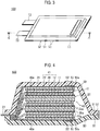
- FIG. 3 is a perspective view showing a stacked battery 100.
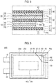
- FIG. 4 is a sectional view taken along line 4-4 in FIG. 3 .
- FIG. 5 is an enlarged sectional view showing the main part of FIG. 4 .
- FIG. 6 is a plan view showing the stacked battery 100 in a state in which a part of an outer layer member is cut away.
- the term "stacking direction" refers to a direction in which electrodes and separators are stacked in the stacked battery 100.
- the stacked battery 100 of the present embodiment has a flat shape. The direction in which a plurality of stacked batteries 100 is stacked coincides with the stacking direction in which the electrodes and the separators are stacked.
- the illustrated battery module 200 includes a plurality of stacked batteries 100 and a holding member 110 that sandwiches and holds the stacked batteries 100 from both sides in the stacking direction.
- the stacked battery 100 includes a power generation element 40 in which a plurality of electrodes 10 and 20 and a plurality of separators 30 are alternately stacked, and an exterior member 50 that accommodates the power generation element 40 ( see FIGS. 3 and 4 ).
- the stacked battery 100 includes first bonding portions 61 for bonding the electrodes 10 and 20 and the separators 30 ( see FIG. 5 ).
- the stacked battery 100 includes second bonding portions 62 for bonding outermost layers 40a of the power generation element 40 and an inner side 50a of the exterior member 50 ( see FIGS. 4 and 6 ).
- the exterior member 50 includes a joint portion 52 in which peripheral edge portions 51 are overlapped and joined ( see FIGS. 4 and 6 ).
- each of the separators 30 includes an outer peripheral edge 30a having a shape similar to a shape of outer peripheral edges 10a and 20a of the electrodes 10 and 20, and has such a size that the outer peripheral edge 30a of each of the separators 30 is located inside the joint portion 52 without being sandwiched by the joint portion 52 ( see FIG. 6 ).
- the stacked battery 100 is also simply referred to as "unit cell 100.” Details will be described below.
- the power generation element 40 includes the positive electrode 10 in which a positive electrode active material layer 12 is disposed on at least one surface of a positive electrode current collector 11, the negative electrode 20 in which a negative electrode active material layer 22 is disposed on at least one surface of a negative electrode current collector 21, and a separator 30 for holding an electrolytic solution.
- a unit cell layer 41 is formed by causing the positive electrode active material layer 12 and the negative electrode active material layer 22 to face each other with the separator 30 interposed therebetween.
- the power generation element 40 is accommodated in the exterior member 50 in a state where a plurality of unit cell layers 41 is stacked.
- the positive electrode current collector 11 has a shape of a thin film made of, for example, aluminum.
- a positive electrode tab 13 for charging and discharging is connected to the positive electrode current collector 11.
- the positive electrode active material layer 12 includes a positive electrode active material such as spinel type lithium manganite, lithium nickel manganese cobalt composite oxide having a layered crystal structure, or the like.
- the negative electrode current collector 21 has a shape of a thin film made of, for example, copper.
- a negative electrode tab 23 for charging and discharging is connected to the negative electrode current collector 21.
- the negative electrode active material layer 22 includes negative electrode active materials. At least one of the negative electrode active materials is selected from the group consisting of graphite, amorphous carbon-coated graphite, silicon (Si), silicon alloy, and silicon oxide.
- An area of the negative electrode active material layer 22 is larger than an area of the positive electrode active material layer 12.
- the separator 30 holds an electrolyte contained in the electrolytic solution.
- a type of the separator 30 is not particularly limited as long as it can hold the electrolyte contained in the electrolytic solution.
- a conventionally known separator may be appropriately used.
- the exterior member 50 accommodates the power generation element 40 together with the electrolytic solution.
- the exterior member 50 is formed of a laminate sheet having a three-layer structure.
- a first innermost layer is formed using a heat-fusible resin, for example, polypropylene (PP), polyethylene (PE), ionomer, or ethylene vinyl acetate (EVA).
- a second layer is formed using a foil-like metal, for example, an Al foil or a Ni foil.
- a third layer is formed using a resinous film, for example, rigid polyethylene terephthalate (PET) or nylon.
- the exterior member 50 has the joint portion 52 where the peripheral edge portions 51 are overlapped and joined.
- the joint portion 52 is formed by overlapping and heating the peripheral edge portions 51 of the exterior member 50 so that the first layers of heat-fusible resin are welded to each other.
- the first bonding portions 61 bond the electrodes 10 and 20 (the positive electrode 10 and the negative electrode 20) and the separators 30.
- a positional shift called a playing card shift.
- the term "playing card shift” means a phenomenon that a position of a constituent member (the electrodes 10 and 20 or the separators 30) at a specific portion of the power generation element 40 is shifted laterally beyond an allowable dimension from a position of the constituent member at another portion.
- the first bonding portions 61 are not provided, the position of the constituent member at the substantially central portion of the power generation element 40 in the stacking direction is easily shifted laterally from the position of the constituent member at another portion.
- a constituent material of the first bonding portions 61 is not limited as long as they can bond the electrodes 10 and 20 and the separator 30.
- the first bonding portions 61 are formed, for example, on both surfaces of a separator base 31 (corresponding to a "base of a separator") and are formed of a bonding layer 32 containing a bonding material.
- the bonding layer 32 is provided over the entire surface or a part of the surface of the separator base 31.
- the separator base 31 it may be possible to use, for example, a porous sheet, a nonwoven fabric, or the like made of a polymer or fiber that absorbs and holds the electrolyte contained in the electrolytic solution.
- the bonding material constituting the bonding layer 32 is not limited as long as it can bond the positive electrode active material layer 12 and the separator base 31 and can bond the negative electrode active material layer 22 and the separator base 31.
- the bonding material it may be possible to use, for example, an olefin-based resin such as polyethylene (PE), polypropylene (PP), or the like, an (meth) acryl-based resin such as polymethyl acrylate (PMA), polymethyl methacrylate (PMMA), or the like, and a fluorine resin such as polyvinylidene fluoride (PVdF), polyvinyl fluoride (PVF), or the like.
- the bonding material of the bonding layer 32 that bonds the positive electrode 10 and the separator base 31 may be the same as or different from the bonding material of the bonding layer 32 that bonds the negative electrode 20 and the separator base 31.
- the first bonding portions 61 are disposed at all locations between the positive electrode 10 and the separator 30 and between the negative electrode 20 and the separator 30. However, it is not necessary to dispose the first bonding portions 61 at all locations between the electrodes 10 and 20 and the separators 30 as long as the playing card shift can be prevented, and the first bonding portions 61 may be disposed at intervals.
- the first bonding portions 61 may be disposed at equal intervals in the stacking direction.
- the first bonding portions 61 may be disposed "densely" at a substantially central portion of the power generation element 40 in the stacking direction, and may be disposed "sparsely” at a portion near the outermost layer 40a of the power generation element 40.
- the separator 30 In the case where the first bonding portions 61 are disposed at intervals, it is possible to use the separator 30 in which the first bonding portion 61 is formed only on one surface of the separator base 31. In a portion where the positive electrode 10 and the negative electrode 20 arranged on both sides of the separator 30 are not bonded together, it is possible to use the separator 30 formed only of the separator base 31 in which the first bonding portions 61 are not formed on both surfaces of the separator base 31.
- the second bonding portions 62 bond the outermost layers 40a of the power generation element 40 and the inner side 50a of the exterior member 50. This can prevent a position of the power generation element 40 with respect to the exterior member 50 from being shifted laterally beyond an allowable dimension when the unit cell 100 receives an impact. When the second bonding portions 62 are not provided, the position of the power generation element 40 is easily shifted laterally with respect to the inner side 50a of the exterior member 50.
- a constituent material of the second bonding portions 62 is not limited as long as it can bond the outermost layers 40a of the power generation element 40 and the inner side 50a of the exterior member 50.
- the second bonding portions 62 includes, for example, bonding agents, adhesives, or double-sided tapes.
- the bonding material constituting the bonding agents, the bonding material constituting the adhesives, or the bonding material constituting bonding layers in the double-sided tapes may be the above-mentioned bonding material constituting the bonding layers 32 in the first bonding portions 61.
- the outermost layer 40a of the power generation element 40 shown in FIG. 4 is the negative electrode current collector 21.
- the outermost layer 40a of the power generation element 40 is not limited to this case.
- the second bonding portions 62 bond the illustrated negative electrode current collector 21 and the inner side 50a of the exterior member 50, and may also bond the negative electrode active material layer 22, the positive electrode current collector 11, the positive electrode active material layer 12, or the separator 30 and the inner side 50a of the exterior member 50.
- the second bonding portions 62 bond the outermost layers 40a of the power generation element 40 and the inner side 50a of the exterior member 50 at a position opposite to a side where the positive electrode tab 13 and the negative electrode tab 23 are connected.
- a bonding force per unit area and a size of the second bonding portions 62 are determined from the viewpoint of sufficiently securing a bonding force that prevents the position of the power generation element 40 with respect to the exterior member 50 from being shifted laterally beyond an allowable dimension when the unit cell 100 receives an impact.
- a rectangular shape shown by a two-dot chain line in FIG. 6 indicates a position where third bonding portions 133 and fourth bonding portions 134 to be used when forming the battery module 200 are located.
- the outer peripheral edge 30a of the separator 30 has a shape similar to the shape of the outer peripheral edges 10a and 20a of the electrodes 10 and 20. Furthermore, the separator 30 has such a size that the outer peripheral edge 30a of the separator 30 is positioned inside the joint portion 52 without being sandwiched by the joint portion 52 of the exterior member 50. Due to such shape and size of the separator 30, the separator 30 does not have a portion that partially protrudes laterally beyond the outer peripheral edges 10a and 20a of the electrodes 10 and 20 (the outer peripheral edge 20a of the larger negative electrode 20 in the illustrated example).
- the shape of the outer peripheral edges 10a and 20a of the electrodes 10 and 20 is rectangular, and the shape of the outer peripheral edge 30a of the separator 30 is also rectangular.
- the separator 30 does not function as a member for joining the power generation element 40 to the exterior member 50. For this reason, when determining the size of the separator 30, it is not necessary to consider the point of joining the separator 30 to the exterior member 50, but it is only necessary to consider ensuring the function of the power generation element 40. Therefore, there is no need to provide a region for joining the separator 30 and the exterior member 50 inside the exterior member 50, and the size of the separator 30 and the exterior member 50 can be made as small as possible. As a result, a ratio of a volume of the power generation element 40 to a volume of the exterior member 50 increases.
- the separator 30 has such a size that the outer peripheral edge 30a of the separator 30 does not protrude laterally beyond the outer peripheral edge 20a of the negative electrode 20. This makes it unnecessary to provide a space in the exterior member 50 to make sure that the outer peripheral edge 30a of the separator 30 is not sandwiched by the joint portion 52 of the exterior member 50.
- the size of the exterior member 50 can be made as small as possible. As a result, the ratio of the volume of the power generation element 40 to the volume of the exterior member 50 can be further increased.
- the size of the separator 30 is not limited to the size shown in FIG. 5 .
- the outer peripheral edge 30a of the separator 30 may have a shape similar to the shape of the outer peripheral edges 10a and 20a of the electrodes 10 and 20, and the separator 30 may have such a size that the outer peripheral edge 30a is located inside the joint portion 52 without being sandwiched by the joint portion 52. That is, the separator 30 may not have a portion that partially protrudes laterally beyond the outer peripheral edges 10a and 20a of the electrodes 10 and 20.
- the outer peripheral edge 30a of the separator 30 may be smaller than the outer peripheral edge 20a of the negative electrode 20. Furthermore, the outer peripheral edge 30a of the separator 30 may have a shape similar to the shape of the outer peripheral edges 10a and 20a of the electrodes 10 and 20, and the outer peripheral edge 30a of the separator 30 may be larger than the outer peripheral edge 20a of the negative electrode 20.
- the battery module 200 includes a plurality of unit cells 100, the holding member 110 that sandwiches and holds the unit cells 100 from both sides in the stacking direction, and a pressing part 120 provided in the holding member 110 and configured to press the unit cells 100 with a pressing force acting along the stacking direction.
- the battery module 200 further includes the third bonding portions 133 that bond the unit cells 100 to the holding member 110 and the fourth bonding portions 134 that bond the unit cells 100 to each other.
- the second bonding portions 62 bond the outermost layers 40a of the power generation element 40 and the inner side 50a of the exterior member 50 in a region that does not overlap with the region where the pressing part 120 and the third bonding portions 133 are present ( see also FIGS. 4 and 5 ). Furthermore, when the unit cells 100 are viewed in a plan view from the stacking direction, the second bonding portions 62 bond the outermost layers 40a of the power generation element 40 and the inner side 50a of the exterior member 50 in a region that does not overlap with the region where the fourth bonding portions 134 are present (see also FIG. 6 ). Details will be described below.
- the unit cells 100 have a flat shape.
- the direction in which the unit cells 100 are stacked coincides with the stacking direction in which the electrodes 10 and 20 and the separators 30 are stacked.
- portions indicated by reference numeral 53 exaggerate bulges that appear on the surfaces of the exterior members 50 by providing the second bonding portions 62.
- a dimension of the bulges 53 of the exterior members 50 is about 30 ⁇ m on one side.
- the holding member 110 includes an upper holding member 111 and a lower holding member 112.
- the upper holding member 111 and the lower holding member 112 have a plate shape and are made of a metallic material such as aluminum or the like.
- the upper holding member 111 and the lower holding member 112 have through holes 113 through which through bolts (not shown) are inserted. Four through holes 113 are formed.
- the stacked unit cells 100 are sandwiched between the upper holding member 111 and the lower holding member 112 from both sides in the stacking direction.
- the upper holding member 111 and the lower holding member 112 are fastened by the through bolts.
- hollow sleeves 114 into which the through bolts are inserted are disposed between the upper holding member 111 and the lower holding member 112 ( see FIG. 1 ).
- the pressing part 120 is formed of a bulging portion 121 formed at a central portion of the upper holding member 111.
- the bulging portion 121 bulges toward the stacked unit cells 100.
- the bulging portion 121 has a concave camber shape.
- the bulging portion 121 has a pressing surface 122 to which the third bonding portion 133 is attached, and an inclined surface 123 which obliquely extends from the pressing surface 122.
- the pressing surface 122 of the bulging portion 121 is bonded to an end surface of the uppermost unit cell 100 among the stacked unit cells 100 via the third bonding portion 133.
- the lowermost unit cell 100 is bonded to the lower holding member 112 through the third bonding portion 133. Then, by fastening the upper holding member 111 and the lower holding member 112, a pressing force acting in the stacking direction is applied to each unit cell 100.
- the third bonding portions 133 bond the uppermost unit cell 100 and the lowermost unit cell 100 to the holding member 110.
- the third bonding portions 133 are arranged in the central portions of the uppermost unit cell 100 and the lowermost unit cell 100 ( see also the two-dot chain line in FIG. 6 ).
- a constituent material of the third bonding portions 133 is not limited as long as it can bond the unit cells 100 and the holding member 110.
- the third bonding portions 133 include, for example, bonding agents, adhesives, or double-sided tapes.
- the bonding material constituting the bonding agents, the bonding material constituting the adhesives, or the bonding material constituting bonding layers in the double-sided tapes may be the above-mentioned bonding material constituting the bonding layers 32 in the first bonding portions 61.
- the second bonding portions 62 bond the outermost layers 40a of the power generation element 40 and the inner side 50a of the exterior member 50 in a region that does not overlap with the region where the pressing part 120 and the third bonding portion 133 are present ( see also FIG. 6 ).
- a distance between the pressing surface 122 of the pressing part 120 and the end surface of the uppermost unit cell 100 locally becomes small. The pressing force applied to the unit cells 100 is locally increased due to the presence of the second bonding portions 62.
- the second bonding portions 62 are caused to exist in a region that does not overlap with the region where the pressing part 120 and the third bonding portion 133 are present.
- the second bonding portions 62 may exist in a region that overlaps with a region where the inclined surface 123 is present. This is because the inclined surface 123 does not make contact with the unit cell 100 and there is no possibility that the pressing force applied to the unit cell 100 is locally increased.
- a thickness of the second bonding portions 62 in the stacking direction is preferably smaller than a thickness of the third bonding portions 133 in the stacking direction. This is because the holding member 110 (the upper holding member 111 and the lower holding member 112) does not make contact with the bulge 53 of the exterior member 50 and there is no possibility that the pressing force applied to the unit cells 100 is locally increased.
- the fourth bonding portions 134 bond the unit cells 100 to each other.
- the fourth bonding portions 134 have substantially the same size as the third bonding portions 133, and are arranged in the central portions of the unit cells 100 just like the third bonding portions 133 (see also the two-dot chain line in FIG. 6 ).
- a constituent material of the fourth bonding portions 134 is not limited as long as it can bond the unit cells 100 to each other.
- the fourth bonding portions 134 include, for example, bonding agents, adhesives, or double-sided tapes.
- the bonding material constituting the bonding agents, the bonding material constituting the adhesives, or the bonding material constituting bonding layers in the double-sided tapes may be the above-mentioned bonding material constituting the bonding layers 32 in the first bonding portions 61.
- the second bonding portions 62 bond the outermost layers 40a of the power generation element 40 and the inner side 50a of the exterior member 50 in a region that does not overlap with the region where the fourth bonding portions 134 are present ( see also FIG. 6 ).
- the distance between the unit cells 100 locally becomes small. The pressing force applied to the unit cells 100 is locally increased due to the presence of the second bonding portions 62.
- the second bonding portions 62 are caused to exist in a region that does not overlap with the region where the fourth bonding portions 134 are present.
- the thickness of the second bonding portions 62 in the stacking direction is preferably smaller than a half a thickness of the fourth bonding portions 134 in the stacking direction.
- the electrodes 10 and 20 (the positive electrode 10 and the negative electrode 20) and the separator 30 are bonded by the first bonding portions 61.
- the outermost layers 40a of the power generation element 40 and the inner side 50a of the exterior member 50 are bonded by the second bonding portions 62. This can prevent the position of the power generation element 40 with respect to the exterior member 50 from being shifted laterally beyond an allowable dimension when the unit cell 100 receives an impact.
- the outer peripheral edge 30a of the separator 30 has a shape similar to the shape of the outer peripheral edges 10a and 20a of the electrodes 10 and 20, and the separator 30 has such a size that the outer peripheral edge 30a is located inside the joint portion 52 without being sandwiched by the joint portion 52. That is, the separator 30 does not have a portion that partially protrudes laterally beyond the outer peripheral edges 10a and 20a of the electrodes 10 and 20. There is no need to provide a space for joining the outer peripheral edge 30a of the separator 30 and the exterior member 50 inside the exterior member 50. Therefore, the ratio of the volume of the power generation element 40 to the volume of the exterior member 50 is increased, and the volume energy density representing the output energy per unit volume of the unit cell 100 is improved.
- the separator 30 has such a size that the outer peripheral edge 30a of the separator 30 does not protrude laterally beyond the outer peripheral edges 10a and 20a of the electrodes 10 and 20, it is possible to further increase the ratio of the volume of the power generation element 40 to the volume of the exterior member 50. Thus, the volume energy density is further increased.
- the uppermost unit cell 100 and the lowermost unit cell 100 are bonded to the holding member 110 by the third bonding portions 133.
- the unit cells 100 are bonded to each other by the fourth bonding portions 134.
- the second bonding portions 62 bond the outermost layers 40a of the power generation element 40 and the inner side 50a of the exterior member 50 in a region that does not overlap with the region where the pressing part 120 and the third bonding portions 133 are present.
- the second bonding portions 62 bond the outermost layers 40a of the power generation element 40 and the inner side 50a of the exterior member 50 in a region that does not overlap with the region where the fourth bonding portions 134 are present.
- the thickness of the second bonding portions 62 in the stacking direction is smaller than the thickness of the third bonding portions 133 in the stacking direction.
- the holding member 110 (the upper holding member 111 and the lower holding member 112) does not make contact with the bulge 53 of the exterior member 50. There is no possibility that the pressing force applied to the unit cells 100 is locally increased.
- the thickness of the second bonding portions 62 in the stacking direction is smaller than a half the thickness of the fourth bonding portions 134 in the stacking direction.
- the adjacent unit cells 100 do not make contact with each other at the portion of the bulge 53 of the exterior member 50. There is no possibility that the pressing force applied to the unit cells 100 by the pressing part 120 becomes non-uniform.
- the unit cell 100 of the present embodiment includes the power generation element 40, the exterior member 50, the first bonding portions 61 that bond the electrodes 10 and 20 and the separator 30, and the second bonding portions 62 that bond the outermost layers 40a of the power generation element 40 and the inner side 50a of the exterior member 50.
- the exterior member 50 has the joint portion 52.
- the outer peripheral edge 30a of the separator 30 has a shape similar to the shape of the outer peripheral edges 10a and 20a of the electrodes 10 and 20, and the separator 30 has such a size that the outer peripheral edge 30a of the separator 30 is located inside the joint portion 52 without being sandwiched by the joint portion 52.
- the first bonding portions 61 and the second bonding portions 62 can prevent a positional shift called a playing card shift or can prevent the position of the power generation element 40 with respect to the exterior member 50 from being shifted laterally beyond an allowable dimension. Furthermore, there is no need to provide a space for joining the outer peripheral edge 30a of the separator 30 and the exterior member 50 inside the exterior member 50. Thus, the volume energy density is improved. As a result, it is possible to provide the unit cell 100 capable of improving the volume energy density while maintaining the impact resistance.
- the separator 30 has such a size that the outer peripheral edge 30a of the separator 30 does not protrude laterally beyond the outer peripheral edges 10a and 20a of the electrodes 10 and 20.
- the second bonding portions 62 include, for example, bonding agents, adhesives, or double-sided tapes.
- the outermost layers 40a of the power generation element 40 and the inner side 50a of the exterior member 50 can be bonded using an appropriate material.
- the first bonding portions 61 are formed on at least one surface of the separator base 31 and are formed of the bonding layer 32 containing a bonding material.
- the electrodes 10 and 20 and the separators 30 can be bonded using the bonding separators 30, and the stacking operation in a manufacturing process of the power generation element 40 can be easily performed.
- the battery module 200 of the present embodiment is a battery module 200 including at least one unit cell 100, and includes the holding member 110, the pressing part 120, and the third bonding portions 133 that bond the unit cell 100 to the holding member 110.
- the second bonding portions 62 bond the outermost layers 40a of the power generation element 40 and the inner side 50a of the exterior member 50 in a region that does not overlap with the region where the pressing part 120 and the third bonding portions 133 are present.
- the third bonding portions 133 can prevent the unit cells 100 bonded to the holding member 110 from being shifted laterally with respect to the holding member 110 beyond an allowable dimension. Since the second bonding portions 62 exist in the region that does not overlap with the region where the pressing part 120 and the third bonding portions 133 are present, the pressing force applied to the unit cell 100 can be made uniform.
- the third bonding portions 133 include, for example, bonding agents, adhesives, or double-sided tapes.
- the unit cell 100 and the holding member 110 can be bonded using an appropriate material.
- the thickness of the second bonding portions 62 in the stacking direction is smaller than the thickness of the third bonding portions 133 in the stacking direction.
- the holding member 110 does not make contact with the bulge 53 of the exterior member 50. This makes it possible to prevent the pressing force applied to the unit cells 100 from being locally increased.
- the battery module 200 further includes the fourth bonding portions 134 that bond the unit cells 100 sandwiched by the holding member 110 to each other.
- the second bonding portions 62 bond the outermost layers 40a of the power generation element 40 and the inner side 50a of the exterior member 50 in a region that does not overlap with the region where the fourth bonding portions 134 are present.
- the fourth bonding portions 134 can prevent the unit cells 100 other than the unit cells 100 bonded to the holding member 110 from being shifted laterally with respect to the holding member 110 beyond an allowable dimension. Furthermore, the second bonding portions 62 exist in the region which does not overlap with the region where the fourth bonding portions 134 are present. Therefore, the pressing force applied to the unit cells 100 can be made uniform.
- the fourth bonding portions 134 include, for example, bonding agents, adhesives, or double-sided tapes.
- the unit cells 100 can be bonded to each other using an appropriate material.
- the thickness of the second bonding portions 62 in the stacking direction is smaller than a half the thickness of the fourth bonding portions 134 in the stacking direction.
- the adjacent unit cells 100 do not make contact with each other at the portion of the bulge 53 of the exterior member 50. This makes it possible to prevent the pressing force applied to the unit cells 100 by the pressing part 120 from being non-uniform.
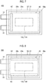
- FIGS. 7, 8 and 9 are plan views showing Modifications 1, 2, and 3 of the arrangement position of the second bonding portions 62, respectively.
- the arrangement position of the second bonding portions 62 is appropriately determined from the viewpoint of preventing the positional shift of the power generation element 40 with respect to the exterior member 50 and from the viewpoint of not overlapping with the region where the third bonding portions 133 and the fourth bonding portions 134 are present.
- the second bonding portions 62 bond the outermost layers 40a of the power generation element 40 and the inner side 50a of the exterior member 50 at positions on the same side as the side to which the positive electrode tab 13 and the negative electrode tab 23 are connected.
- the second bonding portions 62 bond the outermost layers 40a of the power generation element 40 and the inner side 50a of the exterior member 50 at positions extending in parallel with a direction in which the positive electrode tab 13 and the negative electrode tab 23 extend.
- Modification 3 shown in FIG. 9 is directed to a combination of the position of the embodiment and the position of Modification 2.
- the second bonding portions 62 bond the outermost layers 40a of the power generation element 40 and the inner side 50a of the exterior member 50 at positions on the side opposite to the side to which the positive electrode tab 13 and the negative electrode tab 23 are connected and at positions extending in parallel with the direction in which the positive electrode tab 13 and the negative electrode tab 23 extend.
- FIG. 10 is an enlarged sectional view showing a main part of the power generation element 40.
- FIG. 10 corresponds to FIG. 5 .
- the constituent material of the first bonding portions 61 is not limited as long as it can bond the electrodes 10 and 20 and the separators 30.
- a modification of the first bonding portions 61 may be configured by, for example, a bonding layer 33, which is formed on at least one surface of the separator base 31 and includes a bonding material and a heat-resistant material.
- the bonding layer 33 is provided over the entire surface or a part of the surface of the separator base 31.
- the same material as the separator 30 of the embodiment may be used as the separator base 31 and the bonding material.
- Alumina powder, a binder for binding the alumina powder, or the like is used as the heat-resistant material.
- the first bonding portions 61 are configured by the bonding layer 33, which is formed on at least one surface of the separator base 31 and includes a bonding material and a heat-resistant material.
- the electrodes 10 and 20 and the separators 30 can be bonded using the separators 30 having adhesiveness and heat resistance, and the stacking operation in the manufacturing process of the power generation element 40 having improved heat resistance can be easily performed.
- the present disclosure is not limited to this case.
- the present disclosure may also be applied to a battery module 200 in which one unit cell 100 is sandwiched by the holding member 110.
- the third bonding portions 133 for bonding the unit cells 100 to the holding member 110 exist, but the fourth bonding portions 134 for bonding the unit cells 100 to each other do not exist.
- the bulging portion 121 may be provided only in at least one of the upper holding member 111 and the lower holding member 112. Although there is shown the case where the bulging portion 121 is provided on the upper holding member 111, the bulging portion 121 may be provided only on the lower holding member 112. Bulging portions 121 may be provided on both the upper holding member 111 and the lower holding member 112.
- the pressing part 120 is not limited to the case where the holding member 110 includes the camber-shaped bulging portion 121.
- a sheet member provided with a leaf spring portion or a sheet member formed of an elastic material may be interposed between the holding member 110 and the unit cells 100 or between the unit cells 100, thereby forming the pressing part 120.
- 10 positive electrode (electrode), 10a: outer peripheral edge, 11: positive electrode current collector, 12: positive electrode active material layer, 13: positive electrode tab, 20: negative electrode (electrode), 20a: outer peripheral edge, 21: negative electrode current collector, 22: negative electrode active material layer, 23: negative electrode tab, 30: separator, 30a: outer peripheral edge, 31: separator base (base of separator), 32: bonding layer, 33: bonding layer, 40: power generation element, 40a: outermost layer, 41: unit cell layer, 50: exterior member, 50a: inner side of exterior member, 51: peripheral edge portion, 52: joint portion, 53; bulge, 61: first bonding portion, 62: second bonding portion, 100: stacked battery (unit cell), 110: holding member, 111: upper holding member, 112: lower holding member, 120: pressing part, 121: bulging portion, 122: pressing surface, 123: inclined surface, 133: third bonding portion, 134: fourth bonding portion, 200: battery module
Landscapes
- Chemical & Material Sciences (AREA)
- Chemical Kinetics & Catalysis (AREA)
- Electrochemistry (AREA)
- General Chemical & Material Sciences (AREA)
- Engineering & Computer Science (AREA)
- Manufacturing & Machinery (AREA)
- Secondary Cells (AREA)
- Battery Mounting, Suspending (AREA)
- Cell Separators (AREA)
- Sealing Battery Cases Or Jackets (AREA)
Applications Claiming Priority (2)
| Application Number | Priority Date | Filing Date | Title |
|---|---|---|---|
| JP2017177128A JP6943699B2 (ja) | 2017-09-14 | 2017-09-14 | 積層型電池および電池モジュール |
| PCT/JP2018/030217 WO2019054114A1 (ja) | 2017-09-14 | 2018-08-13 | 積層型電池および電池モジュール |
Publications (2)
| Publication Number | Publication Date |
|---|---|
| EP3683877A1 true EP3683877A1 (de) | 2020-07-22 |
| EP3683877A4 EP3683877A4 (de) | 2021-07-21 |
Family
ID=65722704
Family Applications (1)
| Application Number | Title | Priority Date | Filing Date |
|---|---|---|---|
| EP18856849.7A Pending EP3683877A4 (de) | 2017-09-14 | 2018-08-13 | Stapelbatterie und batteriemodul |
Country Status (5)
| Country | Link |
|---|---|
| US (1) | US20200373625A1 (de) |
| EP (1) | EP3683877A4 (de) |
| JP (1) | JP6943699B2 (de) |
| CN (1) | CN111247679B (de) |
| WO (1) | WO2019054114A1 (de) |
Cited By (1)
| Publication number | Priority date | Publication date | Assignee | Title |
|---|---|---|---|---|
| CN116154382A (zh) * | 2023-04-23 | 2023-05-23 | 宁德时代新能源科技股份有限公司 | 电池的箱体、电池以及用电装置 |
Families Citing this family (7)
| Publication number | Priority date | Publication date | Assignee | Title |
|---|---|---|---|---|
| CN111386625A (zh) * | 2017-11-21 | 2020-07-07 | 理百思特有限公司 | 具有设置为最外面电极的负电极的电极组件及包括其的锂离子二次电池 |
| WO2021131914A1 (ja) * | 2019-12-27 | 2021-07-01 | 日本ゼオン株式会社 | 二次電池およびその製造方法 |
| WO2022065841A1 (ko) * | 2020-09-22 | 2022-03-31 | 주식회사 엘지에너지솔루션 | 배터리 모듈, 이를 포함하는 배터리 팩, 및 자동차 |
| CN115133184B (zh) * | 2021-03-29 | 2023-10-03 | 宁德新能源科技有限公司 | 电芯、电池及用电设备 |
| KR102913278B1 (ko) * | 2021-10-29 | 2026-01-15 | 주식회사 엘지에너지솔루션 | 배터리 팩 및 배터리 팩을 포함하는 자동차 |
| KR102867530B1 (ko) * | 2022-06-24 | 2025-10-13 | 삼성에스디아이 주식회사 | 이차 전지 |
| JP7670011B2 (ja) | 2022-09-15 | 2025-04-30 | トヨタ自動車株式会社 | 電池モジュール及びその製造方法 |
Family Cites Families (22)
| Publication number | Priority date | Publication date | Assignee | Title |
|---|---|---|---|---|
| CN1256801A (zh) * | 1998-03-17 | 2000-06-14 | 三菱电机株式会社 | 锂离子电池及其形成方法 |
| JP2001093576A (ja) * | 1999-09-27 | 2001-04-06 | Japan Storage Battery Co Ltd | 非水電解質電池とその製造方法 |
| JP4694030B2 (ja) * | 2001-04-24 | 2011-06-01 | 東芝電池株式会社 | 扁平形非水電解質二次電池 |
| JP2003045477A (ja) * | 2001-08-01 | 2003-02-14 | Toshiba Corp | アルカリ二次電池、ハイブリッドカー及び電気自動車 |
| JP2003086172A (ja) * | 2001-09-12 | 2003-03-20 | Mitsubishi Electric Corp | 2次電池およびその製造方法 |
| JP2007273350A (ja) * | 2006-03-31 | 2007-10-18 | Toyota Motor Corp | 積層型電池およびその製造方法 |
| JP2009211949A (ja) * | 2008-03-04 | 2009-09-17 | Nissan Motor Co Ltd | 非水電解質二次電池 |
| JP5830953B2 (ja) * | 2010-11-17 | 2015-12-09 | ソニー株式会社 | 二次電池、バッテリユニットおよびバッテリモジュール |
| WO2013047778A1 (ja) * | 2011-09-29 | 2013-04-04 | オートモーティブエナジーサプライ株式会社 | 電池とその製造方法 |
| JP5851785B2 (ja) * | 2011-09-29 | 2016-02-03 | オートモーティブエナジーサプライ株式会社 | 電池とその製造方法 |
| US10090553B2 (en) * | 2013-02-15 | 2018-10-02 | Lg Chem, Ltd. | Electrode assembly and method of manufacturing the same |
| CN104638205B (zh) * | 2013-11-14 | 2017-03-01 | 乔信电子股份有限公司 | 叠置式串并联锂电池芯固定盒 |
| JP5892148B2 (ja) * | 2013-12-04 | 2016-03-23 | 株式会社豊田自動織機 | 電池モジュールユニット |
| JP6032233B2 (ja) * | 2014-03-18 | 2016-11-24 | トヨタ自動車株式会社 | 固体電池及びその製造方法並びに組電池及びその製造方法 |
| KR101773105B1 (ko) * | 2014-07-31 | 2017-08-30 | 주식회사 엘지화학 | 배터리 모듈 |
| JP6652127B2 (ja) * | 2015-03-24 | 2020-02-19 | 日本電気株式会社 | 二次電池、二次電池の製造方法、電動車両および蓄電システム |
| JP6775154B2 (ja) * | 2015-08-26 | 2020-10-28 | パナソニックIpマネジメント株式会社 | 蓄電装置 |
| JP6807149B2 (ja) * | 2015-10-06 | 2021-01-06 | Fdk株式会社 | ラミネート型蓄電素子 |
| JP6667254B2 (ja) * | 2015-10-22 | 2020-03-18 | 株式会社エンビジョンAescジャパン | 組電池 |
| JP6704768B2 (ja) | 2016-03-29 | 2020-06-03 | 株式会社総合車両製作所 | 摩擦攪拌接合方法 |
| WO2018105236A1 (ja) * | 2016-12-09 | 2018-06-14 | 株式会社村田製作所 | 電池パック |
| JP7008430B2 (ja) * | 2017-05-19 | 2022-02-10 | Fdk株式会社 | ラミネート型蓄電素子 |
-
2017
- 2017-09-14 JP JP2017177128A patent/JP6943699B2/ja active Active
-
2018
- 2018-08-13 WO PCT/JP2018/030217 patent/WO2019054114A1/ja not_active Ceased
- 2018-08-13 CN CN201880056480.XA patent/CN111247679B/zh active Active
- 2018-08-13 US US16/642,581 patent/US20200373625A1/en not_active Abandoned
- 2018-08-13 EP EP18856849.7A patent/EP3683877A4/de active Pending
Cited By (2)
| Publication number | Priority date | Publication date | Assignee | Title |
|---|---|---|---|---|
| CN116154382A (zh) * | 2023-04-23 | 2023-05-23 | 宁德时代新能源科技股份有限公司 | 电池的箱体、电池以及用电装置 |
| CN116154382B (zh) * | 2023-04-23 | 2023-09-15 | 宁德时代新能源科技股份有限公司 | 电池的箱体、电池以及用电装置 |
Also Published As
| Publication number | Publication date |
|---|---|
| CN111247679B (zh) | 2023-10-20 |
| JP6943699B2 (ja) | 2021-10-06 |
| WO2019054114A1 (ja) | 2019-03-21 |
| EP3683877A4 (de) | 2021-07-21 |
| CN111247679A (zh) | 2020-06-05 |
| JP2019053892A (ja) | 2019-04-04 |
| US20200373625A1 (en) | 2020-11-26 |
Similar Documents
| Publication | Publication Date | Title |
|---|---|---|
| EP3683877A1 (de) | Stapelbatterie und batteriemodul | |
| JP6859059B2 (ja) | リチウムイオン二次電池及びその製造方法 | |
| JP5252871B2 (ja) | 積層式電池 | |
| JP6315269B2 (ja) | 密閉型電池モジュール及びその製造方法 | |
| CN107851852B (zh) | 蓄电装置 | |
| KR101156955B1 (ko) | 안전성이 향상된 전극조립체 및 이를 포함하는 이차전지 | |
| CN208014826U (zh) | 高输出电池及电池壳体 | |
| KR101170881B1 (ko) | 직렬 연결 구조의 고출력 이차전지 | |
| JP2015520932A (ja) | 単一電極端子結合部を有する電池組合体 | |
| JP5028812B2 (ja) | 電池モジュール | |
| CN111630699B (zh) | 二次电池 | |
| WO2012176517A1 (ja) | 積層型電池およびその製造方法 | |
| KR20110128085A (ko) | 전극 어셈블리, 이차 전지, 및 전극의 제조 방법 | |
| WO2006114993A1 (ja) | 電極積層体および電気デバイス | |
| JP2023097584A (ja) | ラミネート型二次電池 | |
| JP5205713B2 (ja) | 双極型二次電池 | |
| US11276897B2 (en) | Stacked battery and battery module | |
| JP2019102167A (ja) | 電気化学デバイス | |
| JP5526514B2 (ja) | 双極型電池、およびこれを用いた組電池 | |
| KR100910624B1 (ko) | 중첩식 이차전지 | |
| JP2013004260A (ja) | ラミネート型電池およびラミネート型電池からなる組電池 | |
| JP2006351361A (ja) | フィルム外装型蓄電装置 | |
| KR20190055994A (ko) | 이차 전지 | |
| JP7845761B2 (ja) | パウチ型電池セルおよびこれを含む電池モジュール | |
| JP2008091268A (ja) | 薄型電池 |
Legal Events
| Date | Code | Title | Description |
|---|---|---|---|
| STAA | Information on the status of an ep patent application or granted ep patent |
Free format text: STATUS: THE INTERNATIONAL PUBLICATION HAS BEEN MADE |
|
| PUAI | Public reference made under article 153(3) epc to a published international application that has entered the european phase |
Free format text: ORIGINAL CODE: 0009012 |
|
| STAA | Information on the status of an ep patent application or granted ep patent |
Free format text: STATUS: REQUEST FOR EXAMINATION WAS MADE |
|
| 17P | Request for examination filed |
Effective date: 20200227 |
|
| AK | Designated contracting states |
Kind code of ref document: A1 Designated state(s): AL AT BE BG CH CY CZ DE DK EE ES FI FR GB GR HR HU IE IS IT LI LT LU LV MC MK MT NL NO PL PT RO RS SE SI SK SM TR |
|
| AX | Request for extension of the european patent |
Extension state: BA ME |
|
| DAV | Request for validation of the european patent (deleted) | ||
| DAX | Request for extension of the european patent (deleted) | ||
| A4 | Supplementary search report drawn up and despatched |
Effective date: 20210618 |
|
| RIC1 | Information provided on ipc code assigned before grant |
Ipc: H01M 10/04 20060101AFI20210614BHEP Ipc: H01M 10/0585 20100101ALI20210614BHEP Ipc: H01M 50/103 20210101ALI20210614BHEP Ipc: H01M 50/105 20210101ALI20210614BHEP Ipc: H01M 50/209 20210101ALI20210614BHEP Ipc: H01M 50/211 20210101ALI20210614BHEP Ipc: H01M 50/242 20210101ALI20210614BHEP Ipc: H01M 50/262 20210101ALI20210614BHEP Ipc: H01M 50/271 20210101ALI20210614BHEP Ipc: H01M 50/557 20210101ALI20210614BHEP |
|
| P01 | Opt-out of the competence of the unified patent court (upc) registered |
Effective date: 20230412 |
|
| STAA | Information on the status of an ep patent application or granted ep patent |
Free format text: STATUS: EXAMINATION IS IN PROGRESS |
|
| 17Q | First examination report despatched |
Effective date: 20240307 |