EP3683892A2 - Connecteur électrique - Google Patents
Connecteur électrique Download PDFInfo
- Publication number
- EP3683892A2 EP3683892A2 EP20151635.8A EP20151635A EP3683892A2 EP 3683892 A2 EP3683892 A2 EP 3683892A2 EP 20151635 A EP20151635 A EP 20151635A EP 3683892 A2 EP3683892 A2 EP 3683892A2
- Authority
- EP
- European Patent Office
- Prior art keywords
- electrical connector
- sleeve
- cable
- insulation body
- receiving portion
- Prior art date
- Legal status (The legal status is an assumption and is not a legal conclusion. Google has not performed a legal analysis and makes no representation as to the accuracy of the status listed.)
- Pending
Links
Images



Classifications
-
- H—ELECTRICITY
- H01—ELECTRIC ELEMENTS
- H01R—ELECTRICALLY-CONDUCTIVE CONNECTIONS; STRUCTURAL ASSOCIATIONS OF A PLURALITY OF MUTUALLY-INSULATED ELECTRICAL CONNECTING ELEMENTS; COUPLING DEVICES; CURRENT COLLECTORS
- H01R24/00—Two-part coupling devices, or either of their cooperating parts, characterised by their overall structure
- H01R24/28—Coupling parts carrying pins, blades or analogous contacts and secured only to wire or cable
-
- H—ELECTRICITY
- H01—ELECTRIC ELEMENTS
- H01R—ELECTRICALLY-CONDUCTIVE CONNECTIONS; STRUCTURAL ASSOCIATIONS OF A PLURALITY OF MUTUALLY-INSULATED ELECTRICAL CONNECTING ELEMENTS; COUPLING DEVICES; CURRENT COLLECTORS
- H01R13/00—Details of coupling devices of the kinds covered by groups H01R12/70 or H01R24/00 - H01R33/00
- H01R13/02—Contact members
- H01R13/04—Pins or blades for co-operation with sockets
-
- H—ELECTRICITY
- H01—ELECTRIC ELEMENTS
- H01R—ELECTRICALLY-CONDUCTIVE CONNECTIONS; STRUCTURAL ASSOCIATIONS OF A PLURALITY OF MUTUALLY-INSULATED ELECTRICAL CONNECTING ELEMENTS; COUPLING DEVICES; CURRENT COLLECTORS
- H01R13/00—Details of coupling devices of the kinds covered by groups H01R12/70 or H01R24/00 - H01R33/00
- H01R13/40—Securing contact members in or to a base or case; Insulating of contact members
- H01R13/405—Securing in non-demountable manner, e.g. moulding, riveting
-
- H—ELECTRICITY
- H01—ELECTRIC ELEMENTS
- H01R—ELECTRICALLY-CONDUCTIVE CONNECTIONS; STRUCTURAL ASSOCIATIONS OF A PLURALITY OF MUTUALLY-INSULATED ELECTRICAL CONNECTING ELEMENTS; COUPLING DEVICES; CURRENT COLLECTORS
- H01R13/00—Details of coupling devices of the kinds covered by groups H01R12/70 or H01R24/00 - H01R33/00
- H01R13/46—Bases; Cases
- H01R13/502—Bases; Cases composed of different pieces
-
- H—ELECTRICITY
- H01—ELECTRIC ELEMENTS
- H01R—ELECTRICALLY-CONDUCTIVE CONNECTIONS; STRUCTURAL ASSOCIATIONS OF A PLURALITY OF MUTUALLY-INSULATED ELECTRICAL CONNECTING ELEMENTS; COUPLING DEVICES; CURRENT COLLECTORS
- H01R13/00—Details of coupling devices of the kinds covered by groups H01R12/70 or H01R24/00 - H01R33/00
- H01R13/46—Bases; Cases
- H01R13/502—Bases; Cases composed of different pieces
- H01R13/512—Bases; Cases composed of different pieces assembled by screw or screws
-
- H—ELECTRICITY
- H01—ELECTRIC ELEMENTS
- H01R—ELECTRICALLY-CONDUCTIVE CONNECTIONS; STRUCTURAL ASSOCIATIONS OF A PLURALITY OF MUTUALLY-INSULATED ELECTRICAL CONNECTING ELEMENTS; COUPLING DEVICES; CURRENT COLLECTORS
- H01R13/00—Details of coupling devices of the kinds covered by groups H01R12/70 or H01R24/00 - H01R33/00
- H01R13/46—Bases; Cases
- H01R13/52—Dustproof, splashproof, drip-proof, waterproof, or flameproof cases
- H01R13/5202—Sealing means between parts of housing or between housing part and a wall, e.g. sealing rings
-
- H—ELECTRICITY
- H01—ELECTRIC ELEMENTS
- H01R—ELECTRICALLY-CONDUCTIVE CONNECTIONS; STRUCTURAL ASSOCIATIONS OF A PLURALITY OF MUTUALLY-INSULATED ELECTRICAL CONNECTING ELEMENTS; COUPLING DEVICES; CURRENT COLLECTORS
- H01R13/00—Details of coupling devices of the kinds covered by groups H01R12/70 or H01R24/00 - H01R33/00
- H01R13/46—Bases; Cases
- H01R13/52—Dustproof, splashproof, drip-proof, waterproof, or flameproof cases
- H01R13/5205—Sealing means between cable and housing, e.g. grommet
-
- H—ELECTRICITY
- H01—ELECTRIC ELEMENTS
- H01R—ELECTRICALLY-CONDUCTIVE CONNECTIONS; STRUCTURAL ASSOCIATIONS OF A PLURALITY OF MUTUALLY-INSULATED ELECTRICAL CONNECTING ELEMENTS; COUPLING DEVICES; CURRENT COLLECTORS
- H01R13/00—Details of coupling devices of the kinds covered by groups H01R12/70 or H01R24/00 - H01R33/00
- H01R13/46—Bases; Cases
- H01R13/52—Dustproof, splashproof, drip-proof, waterproof, or flameproof cases
- H01R13/5219—Sealing means between coupling parts, e.g. interfacial seal
-
- H—ELECTRICITY
- H01—ELECTRIC ELEMENTS
- H01R—ELECTRICALLY-CONDUCTIVE CONNECTIONS; STRUCTURAL ASSOCIATIONS OF A PLURALITY OF MUTUALLY-INSULATED ELECTRICAL CONNECTING ELEMENTS; COUPLING DEVICES; CURRENT COLLECTORS
- H01R13/00—Details of coupling devices of the kinds covered by groups H01R12/70 or H01R24/00 - H01R33/00
- H01R13/62—Means for facilitating engagement or disengagement of coupling parts or for holding them in engagement
- H01R13/625—Casing or ring with bayonet engagement
-
- H—ELECTRICITY
- H01—ELECTRIC ELEMENTS
- H01R—ELECTRICALLY-CONDUCTIVE CONNECTIONS; STRUCTURAL ASSOCIATIONS OF A PLURALITY OF MUTUALLY-INSULATED ELECTRICAL CONNECTING ELEMENTS; COUPLING DEVICES; CURRENT COLLECTORS
- H01R13/00—Details of coupling devices of the kinds covered by groups H01R12/70 or H01R24/00 - H01R33/00
- H01R13/64—Means for preventing incorrect coupling
-
- H—ELECTRICITY
- H01—ELECTRIC ELEMENTS
- H01R—ELECTRICALLY-CONDUCTIVE CONNECTIONS; STRUCTURAL ASSOCIATIONS OF A PLURALITY OF MUTUALLY-INSULATED ELECTRICAL CONNECTING ELEMENTS; COUPLING DEVICES; CURRENT COLLECTORS
- H01R13/00—Details of coupling devices of the kinds covered by groups H01R12/70 or H01R24/00 - H01R33/00
- H01R13/648—Protective earth or shield arrangements on coupling devices, e.g. anti-static shielding
- H01R13/658—High frequency shielding arrangements, e.g. against EMI [Electro-Magnetic Interference] or EMP [Electro-Magnetic Pulse]
- H01R13/6581—Shield structure
-
- H—ELECTRICITY
- H01—ELECTRIC ELEMENTS
- H01R—ELECTRICALLY-CONDUCTIVE CONNECTIONS; STRUCTURAL ASSOCIATIONS OF A PLURALITY OF MUTUALLY-INSULATED ELECTRICAL CONNECTING ELEMENTS; COUPLING DEVICES; CURRENT COLLECTORS
- H01R13/00—Details of coupling devices of the kinds covered by groups H01R12/70 or H01R24/00 - H01R33/00
- H01R13/648—Protective earth or shield arrangements on coupling devices, e.g. anti-static shielding
- H01R13/658—High frequency shielding arrangements, e.g. against EMI [Electro-Magnetic Interference] or EMP [Electro-Magnetic Pulse]
- H01R13/6581—Shield structure
- H01R13/6582—Shield structure with resilient means for engaging mating connector
-
- H—ELECTRICITY
- H01—ELECTRIC ELEMENTS
- H01R—ELECTRICALLY-CONDUCTIVE CONNECTIONS; STRUCTURAL ASSOCIATIONS OF A PLURALITY OF MUTUALLY-INSULATED ELECTRICAL CONNECTING ELEMENTS; COUPLING DEVICES; CURRENT COLLECTORS
- H01R13/00—Details of coupling devices of the kinds covered by groups H01R12/70 or H01R24/00 - H01R33/00
- H01R13/648—Protective earth or shield arrangements on coupling devices, e.g. anti-static shielding
- H01R13/658—High frequency shielding arrangements, e.g. against EMI [Electro-Magnetic Interference] or EMP [Electro-Magnetic Pulse]
- H01R13/6591—Specific features or arrangements of connection of shield to conductive members
- H01R13/6592—Specific features or arrangements of connection of shield to conductive members the conductive member being a shielded cable
-
- H—ELECTRICITY
- H01—ELECTRIC ELEMENTS
- H01R—ELECTRICALLY-CONDUCTIVE CONNECTIONS; STRUCTURAL ASSOCIATIONS OF A PLURALITY OF MUTUALLY-INSULATED ELECTRICAL CONNECTING ELEMENTS; COUPLING DEVICES; CURRENT COLLECTORS
- H01R4/00—Electrically-conductive connections between two or more conductive members in direct contact, i.e. touching one another; Means for effecting or maintaining such contact; Electrically-conductive connections having two or more spaced connecting locations for conductors and using contact members penetrating insulation
- H01R4/28—Clamped connections, spring connections
- H01R4/30—Clamped connections, spring connections utilising a screw or nut clamping member
- H01R4/36—Conductive members located under tip of screw
-
- H—ELECTRICITY
- H01—ELECTRIC ELEMENTS
- H01R—ELECTRICALLY-CONDUCTIVE CONNECTIONS; STRUCTURAL ASSOCIATIONS OF A PLURALITY OF MUTUALLY-INSULATED ELECTRICAL CONNECTING ELEMENTS; COUPLING DEVICES; CURRENT COLLECTORS
- H01R13/00—Details of coupling devices of the kinds covered by groups H01R12/70 or H01R24/00 - H01R33/00
- H01R13/62—Means for facilitating engagement or disengagement of coupling parts or for holding them in engagement
- H01R13/622—Screw-ring or screw-casing
-
- H—ELECTRICITY
- H01—ELECTRIC ELEMENTS
- H01R—ELECTRICALLY-CONDUCTIVE CONNECTIONS; STRUCTURAL ASSOCIATIONS OF A PLURALITY OF MUTUALLY-INSULATED ELECTRICAL CONNECTING ELEMENTS; COUPLING DEVICES; CURRENT COLLECTORS
- H01R9/00—Structural associations of a plurality of mutually-insulated electrical connecting elements, e.g. terminal strips or terminal blocks; Terminals or binding posts mounted upon a base or in a case; Bases therefor
- H01R9/03—Connectors arranged to contact a plurality of the conductors of a multiconductor cable, e.g. tapping connections
- H01R9/05—Connectors arranged to contact a plurality of the conductors of a multiconductor cable, e.g. tapping connections for coaxial cables
- H01R9/0527—Connection to outer conductor by action of a resilient member, e.g. spring
Definitions
- At least one embodiment of the disclosure relate to an electrical connector, and more particularly to an electrical connector for connecting a cable.
- a circular electrical connector for a communication device, an instrument, a control device and an electrical device typically comprises an insulation body, a conductive terminal held in the insulation body, a metal housing sleeved over the insulation body, and a cable electrically connected to the conductive terminal.
- a conductive wire of the cable may extend into the metal housing from one end thereof and is electrically connected with the conductive terminal in the metal housing.
- the disclosure has been made to overcome or alleviate at least one aspect of the above mentioned disadvantages.
- An object of the disclosure is to solve at least one of the above problems and disadvantages in the prior art, and an embodiment of the disclosure provides an electrical connector which may simplify an operation of connecting a cable to a conductive terminal.
- an electrical connector adapted to be electrically connected with a cable, comprising: a fixing assembly comprising a receiving portion extending in an axial direction of the electrical connector, an end of the cable being inserted into the receiving portion from a first end of the receiving portion; an insulation body extending from a second end of the receiving portion; and at least one conductive terminal fixed in the insulation body through an overmolding process.
- the conductive terminal includes: a mounting portion mounted in the insulation body and configured to be electrically connected with the conductor of the cable by a bolt member and a contact portion extending from the insulation body.
- the mounting portions is formed as a cylindrical structure extending axially, a side wall of the cylindrical structure is formed with at least one through hole extending axially through which the bolt member passes to abut against a conductor of the cable inserted into the cylindrical structure.
- the insulation body comprises an insertion portion inserted into the receiving portion at the second end of receiving portion, and an extension integrally connected with the insertion portion and located outside the receiving portion.
- the insulation body further comprises a fool-proof portion extending substantially parallel to the contact portion of the conductive terminal from the extension to prevent the contact portion of the conductive terminal from being erroneously inserted into a mating terminal of a mating connector.
- the electrical connector further comprises a first shielding sleeve extending from a second end of the receiving portion and sleeved over the insulation body.
- the fixing assembly further comprises a main cylinder in which the receiving portion is formed and comprising first and second ends opposite to each other.
- the fixing assembly further comprises an elastic sleeve received in the main cylinder and configured to be sleeved over a portion of an exposed braided shielding wire, which is folded back onto an outer sheath of the cable, and to press the folded braided shielding wire against the outer sheath of the cable.
- the fixing assembly further comprises a second shielding sleeve sleeved over a portion of an exposed conductor of the cable and a portion of the elastic sleeve.
- the first shielding sleeve extends to a portion of the second shielding sleeve from the insulation body.
- the fixing assembly further comprises a sealing ring mounted in a groove formed outside of a first end of the main cylinder.
- the fixing assembly further comprises a rotatable sleeve rotatably disposed over the main cylinder.
- the electrical connector further comprises a mounting base mounted on the rotatable sleeve.
- the mounting base comprises a flange provided with a plurality of mounting holes, a receiving sleeve in which the first shielding sleeve extending out of the fixing assembly is received, and a locking member engaged with a mating locking member formed on the rotatable sleeve.
- the locking member comprises an axial protrusion axially protruding from the receiving sleeve, and a locking protrusion radially protruding outwardly outside the axial protrusion.
- a receiving groove radially recessed inwardly is formed outside of the first end of the main cylinder to receive the axial protrusion of the locking member.
- An inner wall of the rotatable sleeve is provided with a locking groove radially recessed outwardly and engaged with the locking projection to lock the fixing assembly and the mounting base together.
- each of the locking protrusion and the locking groove has a substantially L-shape mated with each other to allow the fixing assembly to be locked with or separated from the mounting base by rotating the rotatable sleeve relative to the mounting base.
- the electrical connector further comprises a third shielding sleeve threaded to the second end of the main cylinder, through which the electrical cable pass to be inserted into the main cylinder.
- the electrical connector further comprises a sealing sleeve sleeved over the cable.
- the sealing sleeve comprises a first portion having a small diameter and adapted to be inserted into the first end of the receiving portion and a second portion having a large diameter and adapted to remain outside the first end of the receiving portion and to be pressed between the first end of the main cylinder and an end of the third shielding sleeve so as to seal the first end of the receiving portion.
- the third shielding sleeve has a conical inner wall surface tapering outwardly and adapted to press the second portion of the sealing sleeve against an outer sheath of the cable.
- an end of the first shielding sleeve extending from the extension of the insulation body is provided with a plurality of resilient pieces folded onto the other end the first shielding sleeve.
- the electrical connector is constructed as a circular electrical connector.
- the conductor of the cable is electrically connected with the conductive terminal mounted in the insulation body, thereby simplifying an operation of connecting the cable onto the conductive terminal and decreasing components of the entire electrical connector.
- an electrical connector adapted to be electrically connected with a cable, comprising: a fixing assembly comprising a receiving portion extending in an axial direction of the electrical connector, an end of the cable being inserted into the receiving portion from a first end of the receiving portion; an insulation body extending from a second end of the receiving portion; at least one conductive terminal fixed in the insulation body through an overmolding process.
- the conductive terminal a mounting portion mounted in the insulation body and configured to be electrically connected with the conductor of the cable by a bolt member and a contact portion extending from the insulation body to be electrically connected with a mating terminal of a mating connector; and a first shielding sleeve extending out of the first end of the receiving portion and sleeved over the insulation body.
- the electrical connector according to embodiments of the disclosure is applicable to an electrical device such as a communication device, a meter instrument, a control device, or the like to power the electrical device.
- the electrical connector may be constructed as a circular plug electrical connector and plugged into a receptacle electrical connector mounted on the electrical device.
- FIG. 1 shows a schematic perspective view of an electrical connector according to an exemplary embodiment of the disclosure.
- an electrical connector 100 adapted to be electrically connected with a cable 200 has a generally circular outer profile and comprises a fixing assembly 1, an insulation body 2 and at least one conductive terminal 3.
- FIG. 13 shows a schematic perspective view of an end portion, which is to be connected, of a cable suitable for use in the electrical connector of the disclosure.
- the cable 200 has an outer sheath 202 into which two conductive wires are received.
- a braided shielding wire 203 is disposed between the conductive wires and the outer sheath 202.
- Each of the wires comprises a conductor 201 and an inner sheath 204 wrapped around an external surface of the conductor 201.
- the outer sheath 202 at one end of the cable 200 is partially removed to expose the braided shielding wire 203.
- the exposed braided shield wire 203 is then partially cutting away to expose the two conductive wires.
- the inner sheath 204 of each of the wires is cut away to expose the conductor 201.
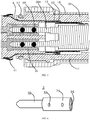
- FIG. 2 shows a schematic longitudinal cross-sectional view of the electrical connector shown in FIG. 1 ;
- FIG. 3 shows a schematic enlarged view of portion A of FIG. 2 ;
- FIG. 4 shows a schematic perspective view of a conductive terminal according to an exemplary embodiment of the disclosure;
- FIG. 5 shows a schematic exploded view of the electrical connector of FIG. 1 wherein a mounting base and a mating connector are shown;
- FIG. 6 shows a schematic exploded view of the electrical connector of FIG. 1 , wherein an insulation body and a first shielding sleeve are not shown;
- FIG. 8 shows a schematic enlarged view of portion C of FIG. 6 ;
- FIG. 9 shows a schematic perspective view of a connection of a conductive terminal with a conductor of a cable.
- the fixing assembly 1 comprises a receiving portion 17 having a cylindrical space and extending in an axial direction of the electrical connector 100.
- An end of the cable 200 is inserted into the receiving portion 17 from a first end (the right end in FIG. 2 ) of the receiving portion 17.
- An insulation body 2 made of for example a plastic material extends out of a second end (the left end in FIG. 2 ) of the receiving portion 17.
- a conductive terminal 3 is fixed in the insulation body 2 through an overmolding process and comprises a mounting portion 31 mounted in the insulation body 2 and configured to be electrically connected with the conductor 201 of the cable 200 by a bolt member 18, and a contact portion 32 extending out of the insulation body 2 to be electrically connected with a mating terminal 301 of a mating connector 300, so that the electrical connector 100 is mated with the mating connector 300.
- the conductive terminal 3 is fixed in a mold, then a molten colloid is injected onto the conductive terminal 3. After the molten colloid is solidified, the conductive terminal 3 will be firmly fixed in the insulation body 2 formed by the molten colloid.
- the electrical connector 100 further comprises a first shielding sleeve 4 extending out of a second end of the receiving portion 17 and sleeved over the insulation body 2 to electromagnetically shield the conductive terminals 3 mounted in the insulation body 2 and the conductor 201.
- the mounting portions 31 of the conductive terminal 3 is formed as a cylindrical structure axially extending, in which an receiving hole 34 extending axially is formed.
- a side wall of the cylindrical structure is provided with at least one through hole 33 extending axially, through which the bolt member 18 passes to abut against the conductor 201 of the cable 200 inserted into the cylindrical structure, so that the conductor 201 is positioned in the mounting portion 31. Since the conductive terminal 3 is fixed in the insulation body 2 through the overmolding process, the conductive terminal 3 may be firmly fixed in the insulation body 2, thereby avoiding the conductive terminal 3 from moving and/or rotating relative to the insulation body 2 during the mating of the electric connector 100 with the mating connector 300 through plugging.
- the conductor 201 is held in the conductive terminal 3 by the bolt member 18, which simplifies an operation of connecting the conductor and reduces the number of the parts. Further, it is possible to increase a conductive capacity of the conductor and the conductive terminal, for example, it is possible to transmit a current of 50 (A) amperes or more.
- the insulation body 2 comprises an insertion portion 21 inserted into the receiving portion 17 at the second end of receiving portion 17, and an extension portion 22 integrally connected with the insertion portion 21 and located outside the receiving portion 17.
- the extension portion 22 is adapted to be inserted into a receiving sleeve of a mounting base as described in detail below.
- the first shielding sleeve 4 sleeved over the extension 22 may electromagnetically shield the conductive terminal 3 located outside the receiving portion 17.
- FIG. 11 shows a schematic perspective view of an electrical connector and a mating connector according to an exemplary embodiment of the disclosure
- FIG. 12 shows a schematic enlarged view of portion D of FIG. 11 .
- the insulation body 2 further comprises: a fool-proof portion 23 extending substantially parallel to the contact portion 32 of the conductive terminal 3 from the extension 22, and adapted to prevent the contact portion 32 of the conductive terminal 3 from being improperly inserted into the mating terminal 301 of the mating connector 300.
- the mounting base of the mating connector 300 is provided with a receiving groove 302.
- the fool-proof portion 23 is aligned with the receiving groove 302
- the electrical connector 100 may be smoothly inserted into the mating connector 300 so that the two conductive terminals 3 of the electrical connector 100 may be properly electrically connected with the mating terminals of the mating connector 300.
- the fool-proof portion 23 is not aligned with the receiving groove 302, the electrical connector 100 cannot be inserted into the mating connector 300 due to the protruding fool-proof portion 23, thereby avoiding an improper insertion of the electrical connector 100.
- FIG. 7 shows a schematic enlarged view of portion B of FIG. 6
- FIG. 8 shows a schematic enlarged view of a portion C of FIG. 6 .
- the fixing assembly 1 further comprises a cylindrical main cylinder 11 in which the receiving portion 17 is formed and including a first end (the right side in FIG. 2 ) and a second end (the left side in FIG. 2 ) opposite to each other.
- the main cylinder 11 comprises a first section 111, a second section 112 and a threaded section 113.
- the first section 111 has an outer diameter greater than that of the second section 112.
- the fixing assembly 1 further comprises an elastic sleeve 12 received in the main cylinder 11 and configured to be sleeved over a portion of the exposed braided shielding wire 203, which is folded back onto the outer sheath 202 of the cable 200, and to press the folded braided shielding wire 203 against the outer sheath 202 of the cable 200.
- the braided shield wire 203 of the cable 200 are reliably held on the outer sheath 202 of the cable 200 by the elastic sleeve 12, thereby improving connection efficiency of the braided shield wire and electromagnetic shielding effect of the electric connector.
- the fixing assembly 1 further comprises a second shielding sleeve 13 sleeved over a portion of the exposed conductor of the cable 200 and a portion of the elastic sleeve 12.
- the first shielding sleeve 4 extends onto a portion of the second shielding sleeve 13 from the insulation body 2.
- the first shielding sleeve 4 and the second shielding sleeve 13 are continuously sleeved over a section, which is from a portion of the uncut outer sheath 202 of the cable 200 to a portion of the conductive terminal 3 which is fixed in the extension 22 of the insulation body2, thereby improving the electromagnetic shielding effect of the electrical connector.
- the fixing assembly 1 further comprises a rotatable sleeve 15 rotatably disposed over the main cylinder 11.
- the rotatable sleeve 15 comprises a first portion 151 having a larger inner diameter and adapted to fit over the first section 114 of the main cylinder 11, and a second portion 152 having a smaller inner diameter and adapted to fit over the second section 112 of the main cylinder 11.
- the main cylinder 11 is formed with a step between the first section 111 and the second sections 112 to prevent the rotatable sleeve 15 from being separated from the first section 111 of the main cylinder 11.
- the electrical connector 100 further comprises a mounting base 5 mounted on the rotatable sleeve 15 to mount the electrical connector 100 on the mounting base 5.
- the mounting base 5 comprises: a flange 51 provided with a plurality of mounting holes 511; a receiving sleeve 52 in which the first shielding sleeve 4 extending out of the fixing assembly 1 and the extension 22 of the insulation body 2 are received; and a locking member 53 engaged with a mating locking member formed on the rotatable sleeve 15.
- an end of the first shielding sleeve 4 extending out of the extension 22 of the insulation body 2 is provided with a plurality of resilient pieces 41 which are folded onto the other end the first shielding sleeve.
- the resilient pieces 41 are compressed against an inner wall of the receiving sleeve 52.
- the fixing assembly 1 further comprises a sealing ring 14 mounted in a groove formed outside of the first end of the main cylinder 11.
- the sealing ring 14 is compressed by the inner wall of the receiving sleeve 52, thereby providing water and moisture proof performance of the electrical connector.
- the locking member 53 comprises an axial protrusion 531 axially protruding from the receiving sleeve 52, and a locking protrusion 532 radially protruding outwardly outside the axial protrusion 531.
- a receiving groove 111 radially recessed inwardly is formed outside of the first end of the main cylinder 11 to receive the axial protrusion 531 of the locking member 53.
- An inner wall of the rotatable sleeve 15 is provided with a locking groove 154 radially recessed outwardly and engaged with the locking projection 532 to lock the fixing assembly 1 and the mounting base 5 together.
- each of the locking protrusion 531 and the locking groove 154 has a substantially L-shape mated with each other to allow the fixing assembly 1 to be locked with or separated from the mounting base 5 by rotating the rotatable sleeve 15 relative to the mounting base 5.
- the rotatable sleeve 15 is provided with an indicator 153 indicating ON or OFF.
- the mounting base 5 is mounted on a mounting panel or mounting bracket of an electrical apparatus by the flange 51.
- the electrical connector 100 further comprises a third shielding sleeve 19 threaded to the second end of the main cylinder 11, through which the electrical cable 200 pass to be inserted into the receiving portion 17 of the main cylinder 11.
- the electrical connector 100 further comprises a sealing sleeve 16 sleeved over the cable 200 and comprising a first portion 161 having a small diameter and adapted to be inserted into the first end of the receiving portion 17, and a second portion 162 having a large diameter and adapted to remain outside the first end of the receiving portion 17 and to be pressed between the first end of the main cylinder 11 and an end of the third shielding sleeve 19 so as to seal the first end of the receiving portion 17.
- a sealing sleeve 16 sleeved over the cable 200 comprising a first portion 161 having a small diameter and adapted to be inserted into the first end of the receiving portion 17, and a second portion 162 having a large diameter and adapted to remain outside the first end of the receiving portion 17 and to be pressed between the first end of the main cylinder 11 and an end of the third shielding sleeve 19 so as to seal the first end of the receiving portion 17.
- the third shielding sleeve 19 has a conical inner wall surface 191 tapering outwardly and adapted to press the second portion 162 of the sealing sleeve 16 against the outer sheath 202 of the cable 200, thereby further improving sealing effect.
- the first, second and third shielding sleeves 4, 13 and 19 described above may be made of a material such as copper, stainless steel or the like.
- the cable 200 may has a circular or rectangular cross-section.
Landscapes
- Details Of Connecting Devices For Male And Female Coupling (AREA)
- Coupling Device And Connection With Printed Circuit (AREA)
Applications Claiming Priority (1)
| Application Number | Priority Date | Filing Date | Title |
|---|---|---|---|
| CN201910037802.2A CN111435777B (zh) | 2019-01-15 | 2019-01-15 | 电连接器 |
Publications (2)
| Publication Number | Publication Date |
|---|---|
| EP3683892A2 true EP3683892A2 (fr) | 2020-07-22 |
| EP3683892A3 EP3683892A3 (fr) | 2020-09-16 |
Family
ID=69167676
Family Applications (1)
| Application Number | Title | Priority Date | Filing Date |
|---|---|---|---|
| EP20151635.8A Pending EP3683892A3 (fr) | 2019-01-15 | 2020-01-14 | Connecteur électrique |
Country Status (3)
| Country | Link |
|---|---|
| US (1) | US11201437B2 (fr) |
| EP (1) | EP3683892A3 (fr) |
| CN (1) | CN111435777B (fr) |
Families Citing this family (10)
| Publication number | Priority date | Publication date | Assignee | Title |
|---|---|---|---|---|
| USD958757S1 (en) * | 2018-03-27 | 2022-07-26 | Jiusheng Zou | Push pull connector with diagonal pattern |
| CN112290300A (zh) * | 2020-09-13 | 2021-01-29 | 泰州市航宇电器有限公司 | 一种应急供电快速连接电连接器结构 |
| CN112332173B (zh) * | 2020-10-28 | 2025-07-15 | 中航光电科技股份有限公司 | 一种连接器及使用该连接器的连接器组件 |
| CN112864743B (zh) * | 2021-03-03 | 2024-06-28 | 苏州祥龙嘉业电子科技股份有限公司 | 一种Fakra电连接器公座组装体 |
| CN116960672A (zh) * | 2022-04-15 | 2023-10-27 | 泰科电子(上海)有限公司 | 线缆连接器组件 |
| US12438318B2 (en) * | 2022-11-11 | 2025-10-07 | Brunswick Corporation | Connectors for electric marine devices |
| USD1093321S1 (en) * | 2024-01-30 | 2025-09-16 | Shenzhen Jieruide Instrument Equipment Co., Ltd. | Waterproof connector |
| USD1094311S1 (en) * | 2024-01-30 | 2025-09-23 | Shenzhen Jieruide Instrument Equipment Co., Ltd. | Waterproof connector |
| CN118554196B (zh) * | 2024-07-29 | 2024-12-20 | 中航光电华亿(沈阳)电子科技有限公司 | 一种水电组合式连接器 |
| CN119890803B (zh) * | 2025-03-25 | 2025-07-08 | 浙江苏源电力工程有限公司 | 光伏电力线缆快速防水密封连接结构 |
Citations (10)
| Publication number | Priority date | Publication date | Assignee | Title |
|---|---|---|---|---|
| US20060003629A1 (en) * | 2004-05-14 | 2006-01-05 | Woodhead Industries, Inc. | Coaxial electrical connector for hazardous locations |
| US20060166560A1 (en) * | 2005-01-26 | 2006-07-27 | Tyco Electronics Corporation | Modular high speed connector assembly |
| CN201549640U (zh) * | 2009-11-26 | 2010-08-11 | 博崴电子股份有限公司 | 电连接器 |
| DE102015003935B3 (de) * | 2015-03-26 | 2016-06-02 | Yamaichi Electronics Deutschland Gmbh | Verbinder, Verfahren und Verwendung |
| US20160294121A1 (en) * | 2015-04-02 | 2016-10-06 | Genesis Technology Usa, Inc. | Three Dimensional Lead-Frames For Reduced Crosstalk |
| US9722383B2 (en) * | 2014-05-07 | 2017-08-01 | Foxconn Interconnect Technology Limited | Electrical connector having insulative housing and method of making the same |
| KR20170136665A (ko) * | 2016-06-01 | 2017-12-12 | 한국전력공사 | 전력량계의 단자대 |
| KR101811357B1 (ko) * | 2016-06-24 | 2017-12-22 | 김근수 | 전원 플러그의 전기접속용 단자 어셈블리 |
| US20170373439A1 (en) * | 2016-06-22 | 2017-12-28 | Foxconn Interconnect Technology Limited | Electrical connector having grounding terminals serving a latching function |
| DE102016215686A1 (de) * | 2016-08-22 | 2018-02-22 | Lq Mechatronik-Systeme Gmbh | Steckverbinder mit angespritztem Isolierkörper und Verfahren zu seiner Herstellung |
Family Cites Families (14)
| Publication number | Priority date | Publication date | Assignee | Title |
|---|---|---|---|---|
| US3646496A (en) * | 1969-07-30 | 1972-02-29 | Williams Instruments | Electrical cable connector and grounding means |
| CA1067590A (fr) * | 1976-06-30 | 1979-12-04 | Sloan Valve Company | Connecteur electrique pour vehicules de remorquage |
| US4307926A (en) * | 1979-04-20 | 1981-12-29 | Amp Inc. | Triaxial connector assembly |
| US5102351A (en) * | 1990-11-29 | 1992-04-07 | The United States Of America As Represented By The Secretary Of The Air Force | Shielded electric cable and harness with strain relief |
| US5386486A (en) * | 1991-11-07 | 1995-01-31 | Litecom, Inc. | Connecting system for field installation and cleaning |
| JP3680173B2 (ja) * | 2002-10-28 | 2005-08-10 | 日本航空電子工業株式会社 | 防水コネクタ |
| JP5003583B2 (ja) * | 2008-04-25 | 2012-08-15 | オムロン株式会社 | コネクタ |
| EP2579396B1 (fr) * | 2011-10-04 | 2016-12-21 | Tyco Electronics Nederland B.V. | Ensemble formant enceinte blindée pour au moins un connecteur standardisé d'un câble en particulier |
| TWI621313B (zh) * | 2016-02-25 | 2018-04-11 | Chen Ching Fu | Signal connector |
| CN206806628U (zh) * | 2017-03-22 | 2017-12-26 | 泰科电子(上海)有限公司 | 连接器 |
| CN206673127U (zh) * | 2017-04-24 | 2017-11-24 | 浙江哈廷电气有限公司 | 一种连接器弹片、接线结构、公插、母插以及连接器 |
| CN207116836U (zh) * | 2017-07-11 | 2018-03-16 | 泰科电子(上海)有限公司 | 连接器 |
| US10431922B2 (en) * | 2017-12-27 | 2019-10-01 | Leviton Manufacturing Co., Inc. | Pin and sleeve device with contact carrier for capturing set screws |
| US10950968B2 (en) * | 2019-02-21 | 2021-03-16 | Eaton Intelligent Power Limited | Electrical connector with a contact holder having transverse openings to receive fasteners |
-
2019
- 2019-01-15 CN CN201910037802.2A patent/CN111435777B/zh active Active
-
2020
- 2020-01-14 EP EP20151635.8A patent/EP3683892A3/fr active Pending
- 2020-01-15 US US16/743,569 patent/US11201437B2/en active Active
Patent Citations (10)
| Publication number | Priority date | Publication date | Assignee | Title |
|---|---|---|---|---|
| US20060003629A1 (en) * | 2004-05-14 | 2006-01-05 | Woodhead Industries, Inc. | Coaxial electrical connector for hazardous locations |
| US20060166560A1 (en) * | 2005-01-26 | 2006-07-27 | Tyco Electronics Corporation | Modular high speed connector assembly |
| CN201549640U (zh) * | 2009-11-26 | 2010-08-11 | 博崴电子股份有限公司 | 电连接器 |
| US9722383B2 (en) * | 2014-05-07 | 2017-08-01 | Foxconn Interconnect Technology Limited | Electrical connector having insulative housing and method of making the same |
| DE102015003935B3 (de) * | 2015-03-26 | 2016-06-02 | Yamaichi Electronics Deutschland Gmbh | Verbinder, Verfahren und Verwendung |
| US20160294121A1 (en) * | 2015-04-02 | 2016-10-06 | Genesis Technology Usa, Inc. | Three Dimensional Lead-Frames For Reduced Crosstalk |
| KR20170136665A (ko) * | 2016-06-01 | 2017-12-12 | 한국전력공사 | 전력량계의 단자대 |
| US20170373439A1 (en) * | 2016-06-22 | 2017-12-28 | Foxconn Interconnect Technology Limited | Electrical connector having grounding terminals serving a latching function |
| KR101811357B1 (ko) * | 2016-06-24 | 2017-12-22 | 김근수 | 전원 플러그의 전기접속용 단자 어셈블리 |
| DE102016215686A1 (de) * | 2016-08-22 | 2018-02-22 | Lq Mechatronik-Systeme Gmbh | Steckverbinder mit angespritztem Isolierkörper und Verfahren zu seiner Herstellung |
Also Published As
| Publication number | Publication date |
|---|---|
| CN111435777B (zh) | 2022-07-22 |
| US11201437B2 (en) | 2021-12-14 |
| EP3683892A3 (fr) | 2020-09-16 |
| US20200227867A1 (en) | 2020-07-16 |
| CN111435777A (zh) | 2020-07-21 |
Similar Documents
| Publication | Publication Date | Title |
|---|---|---|
| EP3683892A2 (fr) | Connecteur électrique | |
| JP6739793B2 (ja) | 同軸コネクタ | |
| EP3203586A1 (fr) | Connecteur électrique | |
| KR970004152B1 (ko) | 전기 접속기용 케이블 차폐 종단 장치 | |
| EP0901193A2 (fr) | Structure pour l'étanchéification de partie terminale d'un câble | |
| KR910013620A (ko) | 원형 din 전기 콘넥터 | |
| EP2980931B1 (fr) | Connecteur electrique | |
| JP2019062732A (ja) | 電気コンタクトデバイス、電気接続ユニット、および電気ケーブルを組み立てる方法 | |
| TWM488766U (zh) | 插接器 | |
| CN216794015U (zh) | 屏蔽连接件、线缆组件和连接器 | |
| KR101701587B1 (ko) | 플러그 커넥터의 절연 바디 | |
| CN101814670A (zh) | 用于插塞连接器的有序排列电缆的嵌件 | |
| EP0431206B1 (fr) | Connecteur à blindage de mise à la terre et procédé | |
| EP3175512A1 (fr) | Connecteurs de câbles coaxiaux avec éléments de retenue de conducteurs | |
| CN101630781A (zh) | 同轴电缆连接器壳体 | |
| EP0111162A1 (fr) | Connecteur enfermé, blindé et mis à la terre | |
| CN113437565A (zh) | 线缆连接器、面板连接器、电路板连接器和连接器组件 | |
| US11038290B2 (en) | Connecting terminal and coaxial connector | |
| CN104737387A (zh) | 用于电缆的端子连接结构 | |
| EP3336970B1 (fr) | Connecteur électrique et procédé d'assemblage d'un connecteur électrique à un câble | |
| CN108140966B (zh) | 具有屏蔽套筒的电缆连接器及其制造方法 | |
| JP5086932B2 (ja) | 電気コネクタ | |
| EP2768087A1 (fr) | Capot de blindage et connecteur de blindage | |
| CN111384645B (zh) | 电连接器和连接器组件 | |
| KR100803437B1 (ko) | 실드 커넥터 |
Legal Events
| Date | Code | Title | Description |
|---|---|---|---|
| PUAI | Public reference made under article 153(3) epc to a published international application that has entered the european phase |
Free format text: ORIGINAL CODE: 0009012 |
|
| STAA | Information on the status of an ep patent application or granted ep patent |
Free format text: STATUS: THE APPLICATION HAS BEEN PUBLISHED |
|
| AK | Designated contracting states |
Kind code of ref document: A2 Designated state(s): AL AT BE BG CH CY CZ DE DK EE ES FI FR GB GR HR HU IE IS IT LI LT LU LV MC MK MT NL NO PL PT RO RS SE SI SK SM TR |
|
| AX | Request for extension of the european patent |
Extension state: BA ME |
|
| PUAL | Search report despatched |
Free format text: ORIGINAL CODE: 0009013 |
|
| AK | Designated contracting states |
Kind code of ref document: A3 Designated state(s): AL AT BE BG CH CY CZ DE DK EE ES FI FR GB GR HR HU IE IS IT LI LT LU LV MC MK MT NL NO PL PT RO RS SE SI SK SM TR |
|
| AX | Request for extension of the european patent |
Extension state: BA ME |
|
| RIC1 | Information provided on ipc code assigned before grant |
Ipc: H01R 4/36 20060101AFI20200810BHEP Ipc: H01R 13/622 20060101ALI20200810BHEP Ipc: H01R 13/6592 20110101ALI20200810BHEP Ipc: H01R 9/05 20060101ALI20200810BHEP Ipc: H01R 9/03 20060101ALI20200810BHEP Ipc: H01R 13/64 20060101ALI20200810BHEP Ipc: H01R 13/405 20060101ALN20200810BHEP Ipc: H01R 13/04 20060101ALI20200810BHEP |
|
| STAA | Information on the status of an ep patent application or granted ep patent |
Free format text: STATUS: REQUEST FOR EXAMINATION WAS MADE |
|
| 17P | Request for examination filed |
Effective date: 20210316 |
|
| RBV | Designated contracting states (corrected) |
Designated state(s): AL AT BE BG CH CY CZ DE DK EE ES FI FR GB GR HR HU IE IS IT LI LT LU LV MC MK MT NL NO PL PT RO RS SE SI SK SM TR |
|
| STAA | Information on the status of an ep patent application or granted ep patent |
Free format text: STATUS: EXAMINATION IS IN PROGRESS |
|
| 17Q | First examination report despatched |
Effective date: 20220211 |