EP3683902A1 - Module de bague collectrice encliquetable - Google Patents
Module de bague collectrice encliquetable Download PDFInfo
- Publication number
- EP3683902A1 EP3683902A1 EP19152302.6A EP19152302A EP3683902A1 EP 3683902 A1 EP3683902 A1 EP 3683902A1 EP 19152302 A EP19152302 A EP 19152302A EP 3683902 A1 EP3683902 A1 EP 3683902A1
- Authority
- EP
- European Patent Office
- Prior art keywords
- slipring
- module
- holder
- holders
- assembly
- Prior art date
- Legal status (The legal status is an assumption and is not a legal conclusion. Google has not performed a legal analysis and makes no representation as to the accuracy of the status listed.)
- Granted
Links
Images


Classifications
-
- H—ELECTRICITY
- H01—ELECTRIC ELEMENTS
- H01R—ELECTRICALLY-CONDUCTIVE CONNECTIONS; STRUCTURAL ASSOCIATIONS OF A PLURALITY OF MUTUALLY-INSULATED ELECTRICAL CONNECTING ELEMENTS; COUPLING DEVICES; CURRENT COLLECTORS
- H01R39/00—Rotary current collectors, distributors or interrupters
- H01R39/02—Details for dynamo electric machines
- H01R39/14—Fastenings of commutators or slip-rings to shafts
-
- H—ELECTRICITY
- H01—ELECTRIC ELEMENTS
- H01R—ELECTRICALLY-CONDUCTIVE CONNECTIONS; STRUCTURAL ASSOCIATIONS OF A PLURALITY OF MUTUALLY-INSULATED ELECTRICAL CONNECTING ELEMENTS; COUPLING DEVICES; CURRENT COLLECTORS
- H01R39/00—Rotary current collectors, distributors or interrupters
- H01R39/02—Details for dynamo electric machines
- H01R39/08—Slip-rings
-
- H—ELECTRICITY
- H01—ELECTRIC ELEMENTS
- H01R—ELECTRICALLY-CONDUCTIVE CONNECTIONS; STRUCTURAL ASSOCIATIONS OF A PLURALITY OF MUTUALLY-INSULATED ELECTRICAL CONNECTING ELEMENTS; COUPLING DEVICES; CURRENT COLLECTORS
- H01R39/00—Rotary current collectors, distributors or interrupters
- H01R39/64—Devices for uninterrupted current collection
- H01R39/643—Devices for uninterrupted current collection through ball or roller bearing
Definitions
- the invention relates to a slipring module bearing sliding tracks of a slipring. Sliprings are used for transferring electrical signals and power between rotating parts.
- EP 1 320 155 A2 A slipring module held by cylindrical metal tube is disclosed in EP 1 320 155 A2 .
- This assembly is comparatively stiff and solid.
- the disadvantage is a high weight and the expensive and complex manufacturing process.
- US 9,742,135 B2 discloses a slipring having sliding tracks mounted to a structured shaft. This is also complex and expensive.
- EP 1482 604 A2 discloses a method of gluing multiple contact rings together with a flange. The flange is used as a chuck in a lathe and as mechanical reference. This method is also complex and expensive.
- the problem to be solved by the invention is to provide a slipring module which is easy and inexpensive to manufacture and which can easily be exchanged in a slipring assembly.
- a slipring module comprises a body and at least one sliding track. There may be at least one of 2, 3, 4, 5, 6, 7, 8, 9, 10 sliding tracks. The maximum number of tracks is determined by the diameter of the module and the technology of contacting the rings. Multiple slipring modules can e.g. be added from a modular construction kit.
- the body has a circular cylindrical shape around a center axis and comprises an electrically insulating material.
- the body may have structural or structure enhancing metal components. It is preferred, if the body comprises insulating material only.
- the insulating material may be any suitable monomer or preferably polymer, for example epoxy or polyurethane.
- the insulating material may also comprise a preferably non-conductive filler, for example ceramic, aluminum oxide or others.
- the modules might also be strengthened by glass fiber mats or metal wire meshes incorporated into the insulating material.
- the sliding tracks are on or at least partially embedded into the insulating material.
- the sliding tracks comprise an electrically conductive material.
- at least two sliding tracks are insulated from each other.
- they are solid conductive bodies. They may comprise any conductive metal or an alloy of metals.
- the slip-ring module For mounting the slipring module into a slipring device, at least one slip-ring holder is provided. Preferably, there are two slipring holders. The slip-ring holders are attached to one or both ends of the slipring module like end caps.
- the slip-ring module has a groove at at least one end, preferably at both ends.
- the groove preferably is at the outside of the cylinder - shaped body, but it may also be at the inner side.
- the groove may have a distance from the end in a range of 2mm and 20mm, preferably between 3mm and 10mm, most preferably between 5mm and 8mm.
- the groove may have a depth in a range of 1mm to 10mm, preferably between 2mm and 6mm, most preferably between 3mm and 5mm.
- the slip-ring holders have a plurality of fingers reaching into the groove when mounted to the slipring module.
- the holders have a circular shape and the fingers are arranged circularly and preferably evenly spaced.
- the fingers provide together with the groove a snap - fit connection which may also be opened if necessary.
- the fingers have at least a certain degree of elasticity to be deformed in such a way that they can reach over the rim of the groove.
- the fingers have an arm and at the end of the arm a protrusion, which fits into the groove.
- the protrusion and the groove may have rounded edges, such that the finger may be removed after assembly.
- the fingers and groove that connect holder and slipring module when mounted may also be located at the inside diameter of the module.
- Elastic fingers also provide some mechanical dampening and shock absorbing properties. This will increase reliability and lifetime of the slipring module.
- the slipring module may be preassembled before mounting into a slip-ring housing by attaching at least one holder (if only one holder is used) or two holders to the ends of the slip-ring module. Such a preassembled slip-ring module may then be inserted into the housing from one side and along its center axis. This is the same way, as slip-ring modules known from prior art are mounted. If a slip-ring housing is already installed in an application, it may be difficult to access the housing from one side to insert the module along its center axis. Here, the slip-ring module may simply be displaced in a radial direction and the holders may be attached or removed, when they module is in place.
- the module may be moved laterally (in a radial direction) into its final position and then one or two holders are pushed on the ends of the slipring modules.
- one or two holders are removed sideward thus releasing the module which may be moved out of the housing laterally (in a radial direction).
- the module may be sufficient to hold the module with only one holder at one end. Normally, the module will be held with one holder at each end. It may also be possible to combine a holder at one end and a bearing fixation as known from prior art at the other end. The module may also be held only by a single holder at a first end while the second end is without mechanical support.
- the at least one holder preferably comprises a plastic material, preferably made from thermosets or thermoplastics. Preferably, it is an injection molded part or a 3D printed part. Alternatively, it may be made of any metal or any other material as long as it provides enough flexibility to the fingers to snap into a groove of the module.
- the at least one holder has a round outer shape. It may have a free inner bore. This inner bore may be used to guide wires to the module or to insert another rotary joint like another slipring, a RF joint, an optical joint or a media joint.
- the at least one holder has a bearing seat for a ball bearing. Such a ball bearing may provide a rotatable support within a housing.
- the at least one sealing ring preferably comprises an elastic material like a polymer or rubber.
- the at least one sealing ring may be compressed by the holding force generated by the fingers.
- the at least one sealing ring generates friction between the module and the holder, such that there is no movement and specifically no rotational movement between the at least one holder and the module.
- the sealing ring could also be realized by 3D printing a ring shaped or wavy structure into the groove of the module or onto the modules front side.
- This shaft lock ring may be used to fix the holder and therefore the module assembly within a slipring housing.
- a shaft lock ring also a snap ring could be used.
- any other spring like a cup spring or+ wave spring could be used as separate part or as printed detail of the module.
- a preferred embodiment is a contrarotating ribbon spring that locks into a hurtling nose in case of rotation of the module (either during assembly or during operation).
- a mechanical stop is of advantage to exactly define the axial position of the module.
- axial springs are provided at the holder.
- the axial springs are one part with the body of the holder.
- springs for example from spring steel may be inserted into gaps of the body of the holder.
- the axial springs assert a force to the holder in axial direction away from the module body. This helps fixing the fingers in the groove of the module and enhances stability, but allows assembly by firmly pressing the holder on the module in an axial direction.
- Axial springs may have different shapes.
- At least one catch is provided for taking up torque, such that the holder cannot rotate relative to the module.
- Another embodiment relates to a double holder with axial springs.
- This double holder basically has the same features and function as the holders described above, but they are double sided to connect two slipring modules together. There may also be an axial spring and/or a catch.
- Another embodiment relates to a double slipring module assembly.
- two modules are connected together by a double holder.
- the double holder has fingers on two axially opposing sides and around a common rotation axis.
- Double holders allow connecting two or more modules together.
- a double holder may comprise any of the features described herein.
- At least one end face of the module body has a hurtling nose to receive counterrotating springs of the at least one holder.
- a slipring assembly comprising a module assembly which further comprises a slipring module and at least one, preferably two holders.
- the assembly may further comprise a stationary part holding a first holder by a first bearing and a rotating part holding a second holder by a second bearing.
- the slipring holders may be coded by different pilot diameters lathed into the front side to prevent a wrong combination of slipring holder and module or a wrong orientation of the module.
- the interface between slipring module and slipring holder may have integrated teeth oriented axially or radially to transfer torque or to code different modules (e.g. for data, signal or power transmission) and ensure their correct orientation during assembly.
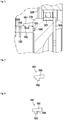
- I slip-ring module 105 comprises a slip-ring module body 110 and a plurality of sliding tracks 120. It is preferred, if the slip-ring module body 110 is of an insulating material which may be epoxy, polyurethane or any other suitable material.
- the sliding tracks 120 preferably are of a conductive material which may be brass, copper, steel or any alloy.
- the conductive material may have a wear-resistant surface and/or a highly conductive surface, which may comprise gold or any other quantities material.
- This embodiment shows a first holder 160 and the left side of the slip-ring module 105 and a second holder 170 at the right side of the slip-ring module 105.
- the holders 160, 170 have a plurality of fingers 181 to fix the holders to the slip-ring module 105. Furthermore, it is preferred, if the at least one groove 186 which allows to insert a shaft lock ring to fix the holders in a slip-ring assembly.
- FIG 2 a sectional view of a slip-ring assembly 200 is shown.
- the slip-ring assembly 200 comprises a stationary part 210 and a rotating part 220 forming a housing for the slip-ring module assembly 100 and holding the slip-ring module assembly 100.
- the slip-ring module assembly 100 comprises at least a slip-ring module body 105 and a plurality of sliding tracks 120.
- the slip-ring module assembly 100 preferably is cylindrical and rotational symmetrical about an axis of rotation 101. There may be minor deviations like the sliding track contact pins 122.
- holders 160 and the 170 are provided, which are held rotatably by ball bearings 211 and 221.
- the holders may have bearing seats 162 and 172.
- at least one sealing ring 184 is placed between the holder and the slip-ring module.
- the sealing ring preferably comprises an elastic material like a polymer or rubber.
- the sealing ring furthermore provides a pre-load to the fingers and results in a more stable connection and may provide dampening of vibrations. It is preferred, if there is a sealing ring groove 183 within one of the holders 160, 170 and/or within at least one of the ends of the slip-ring module 105.
- the fingers 181 of the holders 160, 170 interact with a circular groove 182 at the outside of the slip-ring module 105.
- the groove may be at the inner side of the slip-ring module 105 and the fingers 181 may be arranged at the inner side.
- This figure further shows connecting pins 122 of the sliding tracks 120.
- figure 3 a detail of figure 2 is shown. Here, the section comprising a finger 181 at the second holder 170 is shown enlarged.
- a finger 181 is shown in detail.
- a finger 181 has an arm 190 which further has a protrusion 192 at its end.
- a modified finger 181 is shown.
- the protrusion 192 has an undercut which may interface with a protrusion in groove 182 and which may lock the finger 181 within the module 105.
- Figure 6 shows a second holder 310 with axial springs 311.
- the axial springs are one part with the body of the holder 310.
- the axial springs assert a force to the holder in axial direction away from the module body. This helps fixing the fingers 181 in the groove 182 of the module and enhances stability, but allows assembly by firmly pressing the holder on the module in an axial direction.
- Axial springs may have different shapes.
- the spring 321 shown in the next figure may also be used here.
- the axial stops 316 are shorter in axial direction compared to the locking pin 313 and define the axial position of the holder to a module.
- Figure 7 shows a double holder with axial springs.
- This double holder basically has the same features and function as the holders described above, but they are double sided to connect two slipring modules together.
- Figure 8 shows a double slipring module assembly.
- two modules 105, 315 are connected together by a double holder 320.
- the double holder has fingers 181 on two axially opposing sides and around a common rotation axis.
- the double holder 320 of figure 6 is assembled with two modules 105 and 315 is shown in cross section.
- the axial spring 321 hooks into a catch 131 of the slipring module.
- the axial stop 323 of the double holder 320 defines the axial position of the modules 105, 315 against the double holder.
- the axial spring 321 might slip out of the catch and the counterrotating axial spring 324 hooks into the catch 131 of the slipring module.
Landscapes
- Snaps, Bayonet Connections, Set Pins, And Snap Rings (AREA)
- Rolling Contact Bearings (AREA)
- Power Steering Mechanism (AREA)
- Mutual Connection Of Rods And Tubes (AREA)
Priority Applications (4)
| Application Number | Priority Date | Filing Date | Title |
|---|---|---|---|
| EP19152302.6A EP3683902B1 (fr) | 2019-01-17 | 2019-01-17 | Module de bague collectrice encliquetable |
| EP20700171.0A EP3912232B1 (fr) | 2019-01-17 | 2020-01-13 | Module de bague collectrice encliquetable |
| PCT/EP2020/050668 WO2020148221A1 (fr) | 2019-01-17 | 2020-01-13 | Module d'anneau de glissement à encliquetage |
| CN202080005769.6A CN112868142B (zh) | 2019-01-17 | 2020-01-13 | 咬接式滑环模块 |
Applications Claiming Priority (1)
| Application Number | Priority Date | Filing Date | Title |
|---|---|---|---|
| EP19152302.6A EP3683902B1 (fr) | 2019-01-17 | 2019-01-17 | Module de bague collectrice encliquetable |
Publications (2)
| Publication Number | Publication Date |
|---|---|
| EP3683902A1 true EP3683902A1 (fr) | 2020-07-22 |
| EP3683902B1 EP3683902B1 (fr) | 2022-07-27 |
Family
ID=65036676
Family Applications (2)
| Application Number | Title | Priority Date | Filing Date |
|---|---|---|---|
| EP19152302.6A Active EP3683902B1 (fr) | 2019-01-17 | 2019-01-17 | Module de bague collectrice encliquetable |
| EP20700171.0A Active EP3912232B1 (fr) | 2019-01-17 | 2020-01-13 | Module de bague collectrice encliquetable |
Family Applications After (1)
| Application Number | Title | Priority Date | Filing Date |
|---|---|---|---|
| EP20700171.0A Active EP3912232B1 (fr) | 2019-01-17 | 2020-01-13 | Module de bague collectrice encliquetable |
Country Status (3)
| Country | Link |
|---|---|
| EP (2) | EP3683902B1 (fr) |
| CN (1) | CN112868142B (fr) |
| WO (1) | WO2020148221A1 (fr) |
Families Citing this family (1)
| Publication number | Priority date | Publication date | Assignee | Title |
|---|---|---|---|---|
| DE102023206469A1 (de) | 2023-07-07 | 2025-01-09 | Vitesco Technologies Germany Gmbh | Schleifringmodul, Rotor für eine fremderregte elektrische Maschine und Verfahren zur Herstellung eines Rotors |
Citations (7)
| Publication number | Priority date | Publication date | Assignee | Title |
|---|---|---|---|---|
| US4469972A (en) * | 1982-03-23 | 1984-09-04 | Compagnie Industrielle Des Mecanismes | Commutator for a miniature electric motor |
| WO1990005395A1 (fr) * | 1988-11-12 | 1990-05-17 | Robert Bosch Gmbh | Systeme de bague collectrice |
| EP0967696A2 (fr) * | 1998-06-24 | 1999-12-29 | Jasun Engineering Limited | Dispositif de bague collectrice |
| EP1320155A2 (fr) | 2001-12-15 | 2003-06-18 | Stemmann-Technik GmbH | Transmetteur à bague collectrice |
| EP1482604A2 (fr) | 2003-05-30 | 2004-12-01 | LTN Servotechnik GmbH | Elément de bague collectrice et procédé de fabrication |
| WO2010048956A1 (fr) * | 2008-10-27 | 2010-05-06 | Vestas Wind Systems A/S | Ensemble bague collectrice avec support de tige |
| US9742135B2 (en) | 2012-11-07 | 2017-08-22 | Wobben Properties Gmbh | Slip ring transducer |
Family Cites Families (2)
| Publication number | Priority date | Publication date | Assignee | Title |
|---|---|---|---|---|
| JP2008092706A (ja) * | 2006-10-03 | 2008-04-17 | Nippon Densan Corp | ブラシレスモータおよびこれを搭載するディスク駆動装置 |
| CN205985694U (zh) * | 2016-07-12 | 2017-02-22 | 杭州欣扬科技有限公司 | 一种分体式过孔导电滑环 |
-
2019
- 2019-01-17 EP EP19152302.6A patent/EP3683902B1/fr active Active
-
2020
- 2020-01-13 WO PCT/EP2020/050668 patent/WO2020148221A1/fr not_active Ceased
- 2020-01-13 CN CN202080005769.6A patent/CN112868142B/zh active Active
- 2020-01-13 EP EP20700171.0A patent/EP3912232B1/fr active Active
Patent Citations (7)
| Publication number | Priority date | Publication date | Assignee | Title |
|---|---|---|---|---|
| US4469972A (en) * | 1982-03-23 | 1984-09-04 | Compagnie Industrielle Des Mecanismes | Commutator for a miniature electric motor |
| WO1990005395A1 (fr) * | 1988-11-12 | 1990-05-17 | Robert Bosch Gmbh | Systeme de bague collectrice |
| EP0967696A2 (fr) * | 1998-06-24 | 1999-12-29 | Jasun Engineering Limited | Dispositif de bague collectrice |
| EP1320155A2 (fr) | 2001-12-15 | 2003-06-18 | Stemmann-Technik GmbH | Transmetteur à bague collectrice |
| EP1482604A2 (fr) | 2003-05-30 | 2004-12-01 | LTN Servotechnik GmbH | Elément de bague collectrice et procédé de fabrication |
| WO2010048956A1 (fr) * | 2008-10-27 | 2010-05-06 | Vestas Wind Systems A/S | Ensemble bague collectrice avec support de tige |
| US9742135B2 (en) | 2012-11-07 | 2017-08-22 | Wobben Properties Gmbh | Slip ring transducer |
Also Published As
| Publication number | Publication date |
|---|---|
| EP3912232A1 (fr) | 2021-11-24 |
| CN112868142B (zh) | 2023-11-07 |
| EP3683902B1 (fr) | 2022-07-27 |
| EP3912232B1 (fr) | 2024-07-03 |
| WO2020148221A1 (fr) | 2020-07-23 |
| CN112868142A (zh) | 2021-05-28 |
Similar Documents
| Publication | Publication Date | Title |
|---|---|---|
| EP3100933B1 (fr) | Dispositif de fonctionnement de rotation | |
| US6333839B1 (en) | Tolerance ring with low consistent installation force profile | |
| US8616897B2 (en) | Slip-ring unit | |
| EP3912232B1 (fr) | Module de bague collectrice encliquetable | |
| CN114061636A (zh) | 回转式编码器的组装方法 | |
| US9570849B2 (en) | Float plate for blind matable electrical cable connectors | |
| US20140346921A1 (en) | Device for retaining a machine component in an electric machine and electric machine | |
| EP2687739A1 (fr) | Ensemble de roulement à contact angulaire destiné à être utilisé dans une colonne de direction | |
| JPH08236238A (ja) | ロータリー電気コネクタ | |
| KR101097111B1 (ko) | 양단 접촉 프루브 | |
| CN114614611A (zh) | 角位移传感器敏感组件 | |
| EP4358375B1 (fr) | Structure de montage d'anneau de mise à la terre de moteur | |
| JP2006084212A (ja) | 両端変位型コンタクトプローブ | |
| CN1071897C (zh) | 复合环构件、特别是一种可装配于滚动轴承的磁性探测构件 | |
| US6007344A (en) | Multiple brush steering wheel commutator | |
| CN101361237B (zh) | 旋转连接器 | |
| EP3199419B1 (fr) | Ensemble palier d'essieu ferroviaire avec surface de montage | |
| EP4188752B1 (fr) | Ressort d'horlogerie à contacts de roulement | |
| US7256713B2 (en) | Absolute angle detecting device | |
| US3551716A (en) | Electric contacts for collector lamellae | |
| US20030124891A1 (en) | Electrical connector between two end points | |
| CN113875099A (zh) | 具有卡口锁的滑环壳体 | |
| CN219221183U (zh) | 减速器 | |
| WO2025057950A1 (fr) | Structure de montage de palier à capteur de rotation intégré | |
| JPH071710B2 (ja) | 集電装置 |
Legal Events
| Date | Code | Title | Description |
|---|---|---|---|
| PUAI | Public reference made under article 153(3) epc to a published international application that has entered the european phase |
Free format text: ORIGINAL CODE: 0009012 |
|
| STAA | Information on the status of an ep patent application or granted ep patent |
Free format text: STATUS: THE APPLICATION HAS BEEN PUBLISHED |
|
| AK | Designated contracting states |
Kind code of ref document: A1 Designated state(s): AL AT BE BG CH CY CZ DE DK EE ES FI FR GB GR HR HU IE IS IT LI LT LU LV MC MK MT NL NO PL PT RO RS SE SI SK SM TR |
|
| AX | Request for extension of the european patent |
Extension state: BA ME |
|
| STAA | Information on the status of an ep patent application or granted ep patent |
Free format text: STATUS: REQUEST FOR EXAMINATION WAS MADE |
|
| 17P | Request for examination filed |
Effective date: 20200922 |
|
| RBV | Designated contracting states (corrected) |
Designated state(s): AL AT BE BG CH CY CZ DE DK EE ES FI FR GB GR HR HU IE IS IT LI LT LU LV MC MK MT NL NO PL PT RO RS SE SI SK SM TR |
|
| STAA | Information on the status of an ep patent application or granted ep patent |
Free format text: STATUS: EXAMINATION IS IN PROGRESS |
|
| 17Q | First examination report despatched |
Effective date: 20210305 |
|
| GRAP | Despatch of communication of intention to grant a patent |
Free format text: ORIGINAL CODE: EPIDOSNIGR1 |
|
| STAA | Information on the status of an ep patent application or granted ep patent |
Free format text: STATUS: GRANT OF PATENT IS INTENDED |
|
| RIC1 | Information provided on ipc code assigned before grant |
Ipc: H01R 39/64 20060101ALN20220120BHEP Ipc: H01R 39/08 20060101ALN20220120BHEP Ipc: H01R 39/14 20060101AFI20220120BHEP |
|
| RIC1 | Information provided on ipc code assigned before grant |
Ipc: H01R 39/64 20060101ALN20220207BHEP Ipc: H01R 39/08 20060101ALN20220207BHEP Ipc: H01R 39/14 20060101AFI20220207BHEP |
|
| INTG | Intention to grant announced |
Effective date: 20220221 |
|
| GRAS | Grant fee paid |
Free format text: ORIGINAL CODE: EPIDOSNIGR3 |
|
| GRAA | (expected) grant |
Free format text: ORIGINAL CODE: 0009210 |
|
| STAA | Information on the status of an ep patent application or granted ep patent |
Free format text: STATUS: THE PATENT HAS BEEN GRANTED |
|
| AK | Designated contracting states |
Kind code of ref document: B1 Designated state(s): AL AT BE BG CH CY CZ DE DK EE ES FI FR GB GR HR HU IE IS IT LI LT LU LV MC MK MT NL NO PL PT RO RS SE SI SK SM TR |
|
| REG | Reference to a national code |
Ref country code: CH Ref legal event code: EP |
|
| REG | Reference to a national code |
Ref country code: AT Ref legal event code: REF Ref document number: 1507714 Country of ref document: AT Kind code of ref document: T Effective date: 20220815 |
|
| REG | Reference to a national code |
Ref country code: DE Ref legal event code: R096 Ref document number: 602019017338 Country of ref document: DE |
|
| REG | Reference to a national code |
Ref country code: IE Ref legal event code: FG4D |
|
| REG | Reference to a national code |
Ref country code: LT Ref legal event code: MG9D |
|
| REG | Reference to a national code |
Ref country code: NL Ref legal event code: MP Effective date: 20220727 |
|
| PG25 | Lapsed in a contracting state [announced via postgrant information from national office to epo] |
Ref country code: SE Free format text: LAPSE BECAUSE OF FAILURE TO SUBMIT A TRANSLATION OF THE DESCRIPTION OR TO PAY THE FEE WITHIN THE PRESCRIBED TIME-LIMIT Effective date: 20220727 Ref country code: RS Free format text: LAPSE BECAUSE OF FAILURE TO SUBMIT A TRANSLATION OF THE DESCRIPTION OR TO PAY THE FEE WITHIN THE PRESCRIBED TIME-LIMIT Effective date: 20220727 Ref country code: PT Free format text: LAPSE BECAUSE OF FAILURE TO SUBMIT A TRANSLATION OF THE DESCRIPTION OR TO PAY THE FEE WITHIN THE PRESCRIBED TIME-LIMIT Effective date: 20221128 Ref country code: NO Free format text: LAPSE BECAUSE OF FAILURE TO SUBMIT A TRANSLATION OF THE DESCRIPTION OR TO PAY THE FEE WITHIN THE PRESCRIBED TIME-LIMIT Effective date: 20221027 Ref country code: NL Free format text: LAPSE BECAUSE OF FAILURE TO SUBMIT A TRANSLATION OF THE DESCRIPTION OR TO PAY THE FEE WITHIN THE PRESCRIBED TIME-LIMIT Effective date: 20220727 Ref country code: LV Free format text: LAPSE BECAUSE OF FAILURE TO SUBMIT A TRANSLATION OF THE DESCRIPTION OR TO PAY THE FEE WITHIN THE PRESCRIBED TIME-LIMIT Effective date: 20220727 Ref country code: LT Free format text: LAPSE BECAUSE OF FAILURE TO SUBMIT A TRANSLATION OF THE DESCRIPTION OR TO PAY THE FEE WITHIN THE PRESCRIBED TIME-LIMIT Effective date: 20220727 Ref country code: FI Free format text: LAPSE BECAUSE OF FAILURE TO SUBMIT A TRANSLATION OF THE DESCRIPTION OR TO PAY THE FEE WITHIN THE PRESCRIBED TIME-LIMIT Effective date: 20220727 Ref country code: ES Free format text: LAPSE BECAUSE OF FAILURE TO SUBMIT A TRANSLATION OF THE DESCRIPTION OR TO PAY THE FEE WITHIN THE PRESCRIBED TIME-LIMIT Effective date: 20220727 |
|
| REG | Reference to a national code |
Ref country code: AT Ref legal event code: MK05 Ref document number: 1507714 Country of ref document: AT Kind code of ref document: T Effective date: 20220727 |
|
| PG25 | Lapsed in a contracting state [announced via postgrant information from national office to epo] |
Ref country code: PL Free format text: LAPSE BECAUSE OF FAILURE TO SUBMIT A TRANSLATION OF THE DESCRIPTION OR TO PAY THE FEE WITHIN THE PRESCRIBED TIME-LIMIT Effective date: 20220727 Ref country code: IS Free format text: LAPSE BECAUSE OF FAILURE TO SUBMIT A TRANSLATION OF THE DESCRIPTION OR TO PAY THE FEE WITHIN THE PRESCRIBED TIME-LIMIT Effective date: 20221127 Ref country code: HR Free format text: LAPSE BECAUSE OF FAILURE TO SUBMIT A TRANSLATION OF THE DESCRIPTION OR TO PAY THE FEE WITHIN THE PRESCRIBED TIME-LIMIT Effective date: 20220727 Ref country code: GR Free format text: LAPSE BECAUSE OF FAILURE TO SUBMIT A TRANSLATION OF THE DESCRIPTION OR TO PAY THE FEE WITHIN THE PRESCRIBED TIME-LIMIT Effective date: 20221028 |
|
| PG25 | Lapsed in a contracting state [announced via postgrant information from national office to epo] |
Ref country code: SM Free format text: LAPSE BECAUSE OF FAILURE TO SUBMIT A TRANSLATION OF THE DESCRIPTION OR TO PAY THE FEE WITHIN THE PRESCRIBED TIME-LIMIT Effective date: 20220727 Ref country code: RO Free format text: LAPSE BECAUSE OF FAILURE TO SUBMIT A TRANSLATION OF THE DESCRIPTION OR TO PAY THE FEE WITHIN THE PRESCRIBED TIME-LIMIT Effective date: 20220727 Ref country code: DK Free format text: LAPSE BECAUSE OF FAILURE TO SUBMIT A TRANSLATION OF THE DESCRIPTION OR TO PAY THE FEE WITHIN THE PRESCRIBED TIME-LIMIT Effective date: 20220727 Ref country code: CZ Free format text: LAPSE BECAUSE OF FAILURE TO SUBMIT A TRANSLATION OF THE DESCRIPTION OR TO PAY THE FEE WITHIN THE PRESCRIBED TIME-LIMIT Effective date: 20220727 Ref country code: AT Free format text: LAPSE BECAUSE OF FAILURE TO SUBMIT A TRANSLATION OF THE DESCRIPTION OR TO PAY THE FEE WITHIN THE PRESCRIBED TIME-LIMIT Effective date: 20220727 |
|
| REG | Reference to a national code |
Ref country code: DE Ref legal event code: R097 Ref document number: 602019017338 Country of ref document: DE |
|
| PG25 | Lapsed in a contracting state [announced via postgrant information from national office to epo] |
Ref country code: SK Free format text: LAPSE BECAUSE OF FAILURE TO SUBMIT A TRANSLATION OF THE DESCRIPTION OR TO PAY THE FEE WITHIN THE PRESCRIBED TIME-LIMIT Effective date: 20220727 Ref country code: EE Free format text: LAPSE BECAUSE OF FAILURE TO SUBMIT A TRANSLATION OF THE DESCRIPTION OR TO PAY THE FEE WITHIN THE PRESCRIBED TIME-LIMIT Effective date: 20220727 |
|
| PLBE | No opposition filed within time limit |
Free format text: ORIGINAL CODE: 0009261 |
|
| STAA | Information on the status of an ep patent application or granted ep patent |
Free format text: STATUS: NO OPPOSITION FILED WITHIN TIME LIMIT |
|
| PG25 | Lapsed in a contracting state [announced via postgrant information from national office to epo] |
Ref country code: AL Free format text: LAPSE BECAUSE OF FAILURE TO SUBMIT A TRANSLATION OF THE DESCRIPTION OR TO PAY THE FEE WITHIN THE PRESCRIBED TIME-LIMIT Effective date: 20220727 |
|
| 26N | No opposition filed |
Effective date: 20230502 |
|
| PG25 | Lapsed in a contracting state [announced via postgrant information from national office to epo] |
Ref country code: SI Free format text: LAPSE BECAUSE OF FAILURE TO SUBMIT A TRANSLATION OF THE DESCRIPTION OR TO PAY THE FEE WITHIN THE PRESCRIBED TIME-LIMIT Effective date: 20220727 |
|
| REG | Reference to a national code |
Ref country code: CH Ref legal event code: PL |
|
| GBPC | Gb: european patent ceased through non-payment of renewal fee |
Effective date: 20230117 |
|
| PG25 | Lapsed in a contracting state [announced via postgrant information from national office to epo] |
Ref country code: LU Free format text: LAPSE BECAUSE OF NON-PAYMENT OF DUE FEES Effective date: 20230117 |
|
| REG | Reference to a national code |
Ref country code: BE Ref legal event code: MM Effective date: 20230131 |
|
| PG25 | Lapsed in a contracting state [announced via postgrant information from national office to epo] |
Ref country code: LI Free format text: LAPSE BECAUSE OF NON-PAYMENT OF DUE FEES Effective date: 20230131 Ref country code: GB Free format text: LAPSE BECAUSE OF NON-PAYMENT OF DUE FEES Effective date: 20230117 Ref country code: CH Free format text: LAPSE BECAUSE OF NON-PAYMENT OF DUE FEES Effective date: 20230131 |
|
| PG25 | Lapsed in a contracting state [announced via postgrant information from national office to epo] |
Ref country code: FR Free format text: LAPSE BECAUSE OF NON-PAYMENT OF DUE FEES Effective date: 20230131 Ref country code: BE Free format text: LAPSE BECAUSE OF NON-PAYMENT OF DUE FEES Effective date: 20230131 |
|
| PG25 | Lapsed in a contracting state [announced via postgrant information from national office to epo] |
Ref country code: IE Free format text: LAPSE BECAUSE OF NON-PAYMENT OF DUE FEES Effective date: 20230117 |
|
| PG25 | Lapsed in a contracting state [announced via postgrant information from national office to epo] |
Ref country code: IT Free format text: LAPSE BECAUSE OF FAILURE TO SUBMIT A TRANSLATION OF THE DESCRIPTION OR TO PAY THE FEE WITHIN THE PRESCRIBED TIME-LIMIT Effective date: 20220727 |
|
| PG25 | Lapsed in a contracting state [announced via postgrant information from national office to epo] |
Ref country code: MC Free format text: LAPSE BECAUSE OF FAILURE TO SUBMIT A TRANSLATION OF THE DESCRIPTION OR TO PAY THE FEE WITHIN THE PRESCRIBED TIME-LIMIT Effective date: 20220727 |
|
| PG25 | Lapsed in a contracting state [announced via postgrant information from national office to epo] |
Ref country code: MC Free format text: LAPSE BECAUSE OF FAILURE TO SUBMIT A TRANSLATION OF THE DESCRIPTION OR TO PAY THE FEE WITHIN THE PRESCRIBED TIME-LIMIT Effective date: 20220727 |
|
| PG25 | Lapsed in a contracting state [announced via postgrant information from national office to epo] |
Ref country code: BG Free format text: LAPSE BECAUSE OF FAILURE TO SUBMIT A TRANSLATION OF THE DESCRIPTION OR TO PAY THE FEE WITHIN THE PRESCRIBED TIME-LIMIT Effective date: 20220727 |
|
| PG25 | Lapsed in a contracting state [announced via postgrant information from national office to epo] |
Ref country code: BG Free format text: LAPSE BECAUSE OF FAILURE TO SUBMIT A TRANSLATION OF THE DESCRIPTION OR TO PAY THE FEE WITHIN THE PRESCRIBED TIME-LIMIT Effective date: 20220727 |
|
| PG25 | Lapsed in a contracting state [announced via postgrant information from national office to epo] |
Ref country code: CY Free format text: LAPSE BECAUSE OF FAILURE TO SUBMIT A TRANSLATION OF THE DESCRIPTION OR TO PAY THE FEE WITHIN THE PRESCRIBED TIME-LIMIT; INVALID AB INITIO Effective date: 20190117 |
|
| PG25 | Lapsed in a contracting state [announced via postgrant information from national office to epo] |
Ref country code: HU Free format text: LAPSE BECAUSE OF FAILURE TO SUBMIT A TRANSLATION OF THE DESCRIPTION OR TO PAY THE FEE WITHIN THE PRESCRIBED TIME-LIMIT; INVALID AB INITIO Effective date: 20190117 |
|
| PG25 | Lapsed in a contracting state [announced via postgrant information from national office to epo] |
Ref country code: TR Free format text: LAPSE BECAUSE OF FAILURE TO SUBMIT A TRANSLATION OF THE DESCRIPTION OR TO PAY THE FEE WITHIN THE PRESCRIBED TIME-LIMIT Effective date: 20220727 |
|
| PGFP | Annual fee paid to national office [announced via postgrant information from national office to epo] |
Ref country code: DE Payment date: 20260120 Year of fee payment: 8 |