EP3683982A1 - Procédé de télémétrie dans un réseau optique passif, point d'extrémité optique et bureau central optique - Google Patents
Procédé de télémétrie dans un réseau optique passif, point d'extrémité optique et bureau central optique Download PDFInfo
- Publication number
- EP3683982A1 EP3683982A1 EP19151901.6A EP19151901A EP3683982A1 EP 3683982 A1 EP3683982 A1 EP 3683982A1 EP 19151901 A EP19151901 A EP 19151901A EP 3683982 A1 EP3683982 A1 EP 3683982A1
- Authority
- EP
- European Patent Office
- Prior art keywords
- optical
- onu
- unranged
- olt
- ranging
- Prior art date
- Legal status (The legal status is an assumption and is not a legal conclusion. Google has not performed a legal analysis and makes no representation as to the accuracy of the status listed.)
- Pending
Links
Images
Classifications
-
- H—ELECTRICITY
- H04—ELECTRIC COMMUNICATION TECHNIQUE
- H04B—TRANSMISSION
- H04B10/00—Transmission systems employing electromagnetic waves other than radio-waves, e.g. infrared, visible or ultraviolet light, or employing corpuscular radiation, e.g. quantum communication
- H04B10/07—Arrangements for monitoring or testing transmission systems; Arrangements for fault measurement of transmission systems
- H04B10/071—Arrangements for monitoring or testing transmission systems; Arrangements for fault measurement of transmission systems using a reflected signal, e.g. using optical time domain reflectometers [OTDR]
Definitions
- Various example embodiments relate to ranging of endpoints in a passive optical network wherein such endpoints are coupled to a central office via shared links of an optical distribution network.
- an optical line termination (abbreviated OLT) in a central office (abbreviated CO) is coupled to multiple optical network units (abbreviated ONUs) in respective optical endpoints via an optical distribution network (ODN).
- ODN typically has a tree and branch architecture and comprises optical fibres and passive splitter/combiners that split the optical signals in the downstream direction from CO to ONUs, and multiplexer the optical signals in the upstream direction from ONUs to CO.
- the OLT at the CO is connected via a single-mode optical fibre - the so-called feeder fibre - to a 1:n passive optical splitter which in turn is connected via n single-mode fibres - the so-called distribution fibres - to the n ONUs in the respective optical endpoints.
- a time-division multiplexing (abbreviated TDM) protocol is used in the downstream direction and a time-division multiple access (abbreviated TDMA) protocol is used in the upstream direction.
- TDM time-division multiplexing
- TDMA time-division multiple access
- each ONU Since ONUs are located at different distances from the OLT, the upstream travel times of their respective transmissions also differ. Therefore, to ensure that data arrive in the correct timeslots at the OLT and prevent collisions between upstream transmissions of different ONUs, the difference in distances from the respective ONUs to the OLT must be compensated for through transmission delays.
- an ONU that is located at a closer distance from the OLT shall apply a larger transmission delay than an ONU that is located at a farther distance from the OLT.
- RTT Round-Trip Time
- Ranging must be applied when a PON is taken into operation and each time a new, unranged ONU connects with the OLT.
- a ranging window that is a time window wherein transmission to/from already ranged ONUs is interrupted in order to enable new, unranged ONUs to range.
- a traditional ranging process enabling new unranged ONUs to range within a ranging time window is unacceptable because the size of the ranging time window is too long to satisfy the latency requirements.
- the latency should stay below 100 a 150 microseconds according to mobile 4G or 5G standards.
- the length of a standard ranging windows wherein no upstream transmissions can take place is in the range of 200 microseconds, which is incompatible with the low latency requirements of mobile 4G or 5G standards.
- the optical fibre coupled to the unranged ONU is exposed to vibrations by an active vibration unit that is integrated in the unranged ONU or located in front of the unranged ONU.
- the optical fibre is exposed to vibrations as soon as the unranged ONU receives a ranging request from the OLT.
- This ranging request may be a standardized signal, recognizable by all ONUs, and transmitted at regular time intervals to invite new unranged ONUs in the PON to start the ranging process.
- Each unranged ONU upon receipt of the ranging request, consequently may start to expose the optical fibre whereto it is coupled to vibrations.
- the vibrations generated by the new unranged ONUs may have the same, predefined frequency, or they may have different frequencies that are either predefined or determined at the time the ranging request is received from the OLT.
- the OLT After having transmitted the ranging request, the OLT also activates an optical reflectometry measurement.
- the optical reflectometry measurement may for instance be executed by a Coherent Rayleigh Optical Domain Reflectometry measurement unit, abbreviated COTDR measurement unit, that sends laser pulses in a certain wavelength along the optical fibres in downstream direction and measures the backscattered Rayleigh signals wherein vibrations are induced by the unranged ONU.
- This raw time information may be forwarded to the OLT or to a management unit that calculates the Round-Trip Time (RTT) between OLT and unranged ONU, or the distance between OLT and unranged ONU, and ultimately also the equalization delay to be applied by the unranged ONU for future data transmission.
- RTT Round-Trip Time
- the COTDR measurement unit itself may calculate the RTT and/or the distance and/or the equalisation delay from the raw time information and deliver the already processed information to the OLT.
- the OLT at last transmits the equalization delay as well as the assigned TDMA timeslot(s), jointly named ranging information, to the unranged ONU. Since upstream transmissions by other ONUs that have already ranged earlier need not be interrupted while the optical fibre is exposed to vibrations by an unranged ONU, a ranging window wherein all upstream transmission is interrupted is no longer required. New, unranged ONUs in other words can range within a PON that is used for applications with low latency requirements like mobile fronthauling.
- the optical reflectometry measurement is performed by a Coherent Rayleigh Optical Time Domain Reflectometry unit, abbreviated COTDR unit, using Distributed Acoustic Sensing, abbreviated DAS.
- a COTDR unit that generates and sends laser pulses in a certain wavelength along an optical fibre and uses Distributed Acoustic Sensing to measure vibrations in the backscattered Rayleigh signals as a function of time after pulse transmission, consequently is a good candidate technology enabling to implement embodiments of the method for ranging an unranged ONU in a PON.
- the COTDR unit may be integrated in the OLT, or in alternative embodiments may be coupled to plural OLTs at a central office via an optical switch such that a single COTDR unit can be used to enable ranging of unranged ONUs in multiple PONs.
- a single COTDR unit may for example serve 8 OLTs or 16 OLTs on a single linecard in the central office. This way, embodiments of the method for ranging of ONUs may be implemented in a cost-efficient manner, sharing the additional hardware needed at the central office across several PONs.
- the method is performed without interruption of data transmission by other ONUs already ranged in said PON.
- embodiments of the method may be used to enable unranged ONUs to range during a ranging window wherein transmission by other ONUs is interrupted
- embodiments of the method are particularly advantageous when performed without interruption of data transmission by other ONUs such that these other ONUs can be used for applications with low latency requirements like for instance 4G/5G mobile fronthauling.
- the frequency of the vibrations generated at or near the unranged ONU is determined as a function of an identity of the unranged ONU.
- an optical endpoint as defined by claim 5, for a passive optical network PON comprising an optical line termination OLT, an optical distribution network ODN and a plurality of optical network units ONUs, the optical endpoint comprising:
- example embodiments of the invention concern an optical endpoint that comprises in addition to an ONU also a vibration unit.
- the vibration unit preferably may be integrated in the ONU to simplify powering and management thereof and to avoid that an additional device must be installed.
- the vibration unit may be a separate device that connects with the ONU and that is installed in front of the ONU.
- the vibration unit incorporates technology that enables to expose the optical fibre coupled to the ONU to vibrations.
- This vibrating technology may be an electromotor, a magnetic component, a piezo-electric transducer, etc.
- the vibrating unit operates under control of the ONU and exposes the optical fibre to vibrations after the ONU has received a ranging request from the OLT.
- the vibrations must have a magnitude and a frequency detectable by an optical reflectometry measurement unit at the OLT that sends laser pulses in the optical fibres of the PON and extracts time information from the sent pulses and their backscattered reflections recognizable through the vibrations induced therein.
- the vibration unit comprises a motor around which the optical fibre of the ODN coupled to the ONU is coiled.
- a possible implementation of the vibration unit relies on an electrical motor that exposes the optical fibre to vibrations.
- the frequency of the motor preferably is controllable such that also the frequency of the vibrations becomes controllable.
- the optical fibre runs along the motor in order to be exposed to the vibrations.
- the accuracy of the RTT, the distance or the equalization delay calculated from the time information extracted during the optical reflectometry measurement increases when the optical fibre is coiled as a fibre spool around the motor. The accuracy further increases with increasing number of windings of the optical fibre around the motor.
- the frequency of the vibrations is determined as a function of an identity of the ONU.
- vibration frequencies that are determined in dependency of an identity of the unranged ONU, for instance the ONU serial number, the ONU address or some other unique ONU identification, helps to distinguish between ONUs in situations where more than one new unranged ONU attempts to range in response to a ranging request from the OLT.
- Alternative embodiments of the method wherein multiple ONUs use the same vibration frequency require an additional step wherein for instance the ONU address or some other identifier is exchanged with the ONU after measurement of the vibrations by the optical reflectometry measurement unit, for example introducing a random delay for activation of the vibration unit and later on performing a correlation between delay and serial number of the ONU.
- an optical central office as defined by claim 8, for a passive optical network PON comprising an optical line termination OLT, an optical distribution network ODN and a plurality of optical network units ONUs, the optical central office comprising:
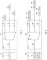
- Fig. 1 shows the typical architecture of a Passive Optical Network or PON.
- An optical line termination, OLT or 111 at a central office, CO or 110, is coupled to multiple optical endpoints, ONU1 or 131, ONU2 or 132, ..., ONUn or 13n, via an optical distribution network, ODN or 120.
- the optical distribution network 120 has a tree-and-branch architecture and thereto comprises a single-mode optical feeder fibre 150, a passive 1:n splitter/multiplexer 121, and n single-mode optical distribution fibres 141, 142, ..., 14n or drop fibres that connect the passive optical splitter to respective ones of the optical endpoints 131, 132, ..., 13n.
- n may for instance be 64.
- the central office 110 shall host multiple OLTs, similar to OLT 111.
- 8 OLTs or 16 OLTs may for instance be integrated on a single linecard.
- the feeder fibre 150 is shared for downstream transmissions towards multiple ONUs and upstream transmissions from multiple ONUs.
- a time-division multiplexing or TDM protocol is used in downstream direction and a time-division multiple access or TDMA protocol is used in upstream direction.
- the ONUs 131, 132, ..., 13n in other words receive data in different timeslots and transmit data in different timeslots assigned to them.
- the difference in distance from the OLT is compensated for through equalisation delays.
- all ONUs are at the same virtual distance from the OLT.
- a ranging process is applied wherein either the round-trip time or distance between the OLT and each of the ONUs is determined, and the difference in RTT or distance is compensated for through an equalisation delay.
- Fig. 2 shows the architecture of a Passive Optical Network wherein the ranging process for a newly connected ONU can be executed without having to interrupt upstream transmission by ONUs that are already operational.
- the PON shown in Fig. 2 again comprises an optical line termination OLT or 211 located in a central office CO or 210.
- the OLT 211 connects with a 1:n passive optical splitter 221 in optical distribution network ODN or 220 via a single-mode optical feeder fibre 250. It is noticed that the optical feeder fibre 250 may be considered to form part of the ODN 220.
- the 1-n passive optical splitter/multiplexer 221 further connects with n optical endpoints via n single-mode optical distribution fibres 241, 242, ..., 24n or drop fibres.
- Each optical endpoint in Fig. 2 comprises an optical network unit and a vibrating unit: the first optical endpoint for instance comprises a first optical network unit ONU1 or 231 and a first vibrating unit VU1 or 261; the second optical endpoint comprises a second optical network unit ONU2 or 232 and a second vibrating unit VU2 or 262; ...; and the n'th optical endpoint comprises an n'th optical network unit ONUn or 23n and an n'th vibrating unit VUn or 26n.
- DAS MU or 212 is connected to the OLT211.
- This DAS measurement unit 212 further optically couples to the feeder fibre 250 via an optical coupler, for instance a 90/10 optical coupler, not drawn in Fig. 2 .
- an optical coupler for instance a 90/10 optical coupler
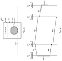
- Fig. 3 illustrates a sample embodiment of the vibration unit 261 of Fig. 2 .
- the embodiment illustrated by Fig. 3 comprises a vibrating module 301 with vibrating motor 302, and control circuitry 303.
- the control circuitry controls activation/deactivation of the motor 302, and the frequency of the motor 302, and therefore receives control signals from the ONU where the vibrating unit 261 connects to, for instance ONU 231 in the example of Fig. 2 .
- the motor 302 exposes the optical distribution fibre 241 that connects with the ONU 231 to vibrations, and may for instance be of the type that is used in cellular phones or smart devices that vibrate as such vibrating motors are generally available at low cost.
- a portion 241' of the optical distribution fibre 241 is winded as a coil around the motor 302.
- the number of windings is selected in view of the desired accuracy of the ranging process. In general, a higher number of windings in the optical fibre coil results in a higher accuracy of the ranging process.
- Fig. 4 illustrates an example embodiment of the method to range a new ONU on a PON where other ONUs are already in operation. It is assumed that in the PON illustrated by Fig. 2 the ONUs 232 ... 23n are already in operation whereas ONU 231 is a new unranged ONU.
- the ranging process for new unranged ONUs like ONU 231 starts by the OLT 211 transmitting a ranging request 401 in the PON.
- Such ranging request 401 is transmitted at regular, given times, and it consists of a standardized signal that is recognizable by the ONUs that receive it.
- ONUs that have already ranged like 232 ... 23n disregard the ranging request 401 when they receive it.
- a new unranged ONU like 231 however upon detection of the ranging request 401 triggers the vibration unit 261 for activation of the vibration.
- the trigger shared between the unranged ONU 231 and the vibration unit 261 is denoted by arrow 402 in Fig. 4 .
- the control circuitry 303 of vibrating unit 261 activates the motor 302 as a result of which vibrations 404 are generated where the optical fibre 241 connected to the unranged ONU 231 is exposed to.
- the OLT 211 triggers the DAS measurement unit 212 to start an optical reflectometry measurement 405.
- the trigger sent from OLT 211 to the DAS measurement unit 212 is denoted by arrow 403 in Fig. 4 .
- the DAS measurement unit 212 Upon receipt of this trigger 403 by the DAS measurement unit 212, the latter starts the optical reflectometry measurement 405 during which laser pulses in a certain wavelength are sent into the PON and a coherent receiver in DAS unit 212 listens for backscattered Rayleigh signals wherein the induced vibrations 404 are detected.
- Distributed Acoustic Sensing implies that the fibre is used by the measurement unit as a distributed sensor to detect the vibrations.
- the DAS measurement unit 212 logs the time of pulse transmission and the time of receipt of the backscattered pulse reflections wherein the vibrations are induced.
- This raw time information 406 is reported to the OLT 211 which calculates therefrom the round-trip time (RTT) between OLT 211 and ONU 231, and/or the distance between OLT 211 and ONU 231, the latter distance being equivalent to the RTT. From the RTT or distance, the OLT 211 further determines the equalization delay that must be applied by ONU 231 in upstream transmissions in order to put ONU 231 at a virtual distance to OLT 211 that is identical to the virtual distance of the other, already operational ONUs 232 ... 23n.
- RTT round-trip time
- ONU 231 became ranged without interrupting the upstream transmissions of the other ONUs 232 ... 23n already operational in the PON.
- This is advantageous in particular of these ONUs 232 ... 23n serve applications like mobile fronthauling wherein 4G mobile data or 5G mobile data have to be upstream transmitted with stringent latency requirements, for instance a maximal latency of 100 microseconds for upstream transmissions up to 10 kilometres.
- a single unranged ONU 231 is responsive to the ranging request 401 from the OLT.
- a mechanism must be foreseen to distinguish between the multiple unranged ONUs.
- One possibility could be to have different unranged ONUs generate vibrations with different frequencies, for example frequencies that are determined in function of a unique identifier of the respective ONUs, for instance the ONU serial number.
- Alternative solutions could lie in a protocol extension that enables the OLT to collect the addresses (or alternative identifiers) of the unranged ONUs when the vibration units of multiple unranged ONUs generate vibrations with the same frequency.
- PON may have more complex tree-and-branch architectures with multiple passive optical splitters/multiplexers that split or combine optical signals on their path from OLT to ONU.
- the method for ranging an unranged ONU however can be applied, irrespective of the architecture or complexity of the PON, as the method requires only modifications at the OLT and ONU side, not in the passive intermediate optical components.
- raw time information is conveyed in 406 from the DAS measurement unit to the OLT. It is remarked that alternative embodiments could be contemplated wherein the DAS measurement unit for instance determines the RTT/distance from the raw time information and provides this already processed info in 406 to the OLT.
- circuitry may refer to one or more or all of the following:
- circuitry also covers an implementation of merely a hardware circuit or processor (or multiple processors) or portion of a hardware circuit or processor and its (or their) accompanying software and/or firmware.
- circuitry also covers, for example and if applicable to the particular claim element, a baseband integrated circuit or processor integrated circuit for a mobile device or a similar integrated circuit in a server, a cellular network device, or other computing or network device.
- top, bottom, over, under, and the like are introduced for descriptive purposes and not necessarily to denote relative positions. It is to be understood that the terms so used are interchangeable under appropriate circumstances and embodiments of the invention are capable of operating according to the present invention in other sequences, or in orientations different from the one(s) described or illustrated above.
Landscapes
- Physics & Mathematics (AREA)
- Electromagnetism (AREA)
- Engineering & Computer Science (AREA)
- Computer Networks & Wireless Communication (AREA)
- Signal Processing (AREA)
- Optical Communication System (AREA)
Priority Applications (1)
| Application Number | Priority Date | Filing Date | Title |
|---|---|---|---|
| EP19151901.6A EP3683982A1 (fr) | 2019-01-15 | 2019-01-15 | Procédé de télémétrie dans un réseau optique passif, point d'extrémité optique et bureau central optique |
Applications Claiming Priority (1)
| Application Number | Priority Date | Filing Date | Title |
|---|---|---|---|
| EP19151901.6A EP3683982A1 (fr) | 2019-01-15 | 2019-01-15 | Procédé de télémétrie dans un réseau optique passif, point d'extrémité optique et bureau central optique |
Publications (1)
| Publication Number | Publication Date |
|---|---|
| EP3683982A1 true EP3683982A1 (fr) | 2020-07-22 |
Family
ID=65041565
Family Applications (1)
| Application Number | Title | Priority Date | Filing Date |
|---|---|---|---|
| EP19151901.6A Pending EP3683982A1 (fr) | 2019-01-15 | 2019-01-15 | Procédé de télémétrie dans un réseau optique passif, point d'extrémité optique et bureau central optique |
Country Status (1)
| Country | Link |
|---|---|
| EP (1) | EP3683982A1 (fr) |
Citations (3)
| Publication number | Priority date | Publication date | Assignee | Title |
|---|---|---|---|---|
| CN102045601A (zh) * | 2009-10-22 | 2011-05-04 | 中兴通讯股份有限公司 | 一种gpon系统中的onu激活方法及系统 |
| EP2615747A2 (fr) * | 2012-04-11 | 2013-07-17 | Huawei Technologies Co., Ltd. | Procédé de télémétrie pour réseau optique passif, système et dispositif |
| EP2670067A1 (fr) * | 2012-05-30 | 2013-12-04 | Broadcom Corporation | Analyse de plante à fibres optiques passives |
-
2019
- 2019-01-15 EP EP19151901.6A patent/EP3683982A1/fr active Pending
Patent Citations (3)
| Publication number | Priority date | Publication date | Assignee | Title |
|---|---|---|---|---|
| CN102045601A (zh) * | 2009-10-22 | 2011-05-04 | 中兴通讯股份有限公司 | 一种gpon系统中的onu激活方法及系统 |
| EP2615747A2 (fr) * | 2012-04-11 | 2013-07-17 | Huawei Technologies Co., Ltd. | Procédé de télémétrie pour réseau optique passif, système et dispositif |
| EP2670067A1 (fr) * | 2012-05-30 | 2013-12-04 | Broadcom Corporation | Analyse de plante à fibres optiques passives |
Non-Patent Citations (1)
| Title |
|---|
| SEBASTIAN GAEDE ET AL: "Overview of Optical Monitoring in Next Generation Optical Access Networks", PHOTONISCHE NETZE 2-3.5.2011 LEIPZIG, 2 May 2011 (2011-05-02), XP055170430 * |
Similar Documents
| Publication | Publication Date | Title |
|---|---|---|
| US10727939B2 (en) | Communication method, optical line terminal, and optical network unit in passive optical network system | |
| JP4442635B2 (ja) | Ponシステムにおける障害通知方法 | |
| KR101790698B1 (ko) | 수동형 광가입자망에서의 광선로 장애 검출 장치 및 방법 | |
| US7680414B2 (en) | Passive optical network system and operating method thereof | |
| EP2403269B1 (fr) | Technologie pour la localisation de défauts dans des réseaux optiques passifs | |
| EP2670067B1 (fr) | Analyse de plante à fibres optiques passives | |
| US7620319B2 (en) | Passive optical network monitoring method and passive optical network | |
| US7616899B2 (en) | Synchronizing method in optical access network, optical switching device, center device, and remote device | |
| US8774623B2 (en) | Passive optical network system and method for detecting fault in optical network terminal | |
| CN108370271B (zh) | 光网络单元的检测方法、装置和无源光网络系统 | |
| JP2008099051A (ja) | Ponシステムおよびそのレンジング方法 | |
| US8180217B2 (en) | Method for coordinating measurements and calibrations in a passive optical network | |
| KR20130093829A (ko) | 광선로 감시 장치 및 방법 | |
| EP3683982A1 (fr) | Procédé de télémétrie dans un réseau optique passif, point d'extrémité optique et bureau central optique | |
| CN115243122B (zh) | 测量链路状态的方法、装置、系统及存储介质 | |
| EP4325740B1 (fr) | Procédé, appareil et système appliqués à un système pon, et support de stockage | |
| EP2819323B1 (fr) | Détection d'injection de signal étranger dans des réseaux optiques passifs | |
| JP6040329B1 (ja) | 測定装置及び測定方法 | |
| Oishi et al. | ONU tester for diagnosis of TDMA-PON using multi-point control protocol messages | |
| WO2009145066A1 (fr) | Système de communication optique, procédé de communication optique et dispositif relais | |
| HK1188045B (en) | Optical line terminal olt | |
| KR20050018093A (ko) | 광전송 시스템의 광네트워크 유니트의 광송신부 측정장치및 그 제어방법 | |
| KR20170058297A (ko) | Onu의 광 트랜시버의 파장 출력 특성에 따라 onu의 파장을 조절하는 등록 방법 | |
| HK1186587A1 (zh) | 在受保护的无源光网络中的无关於均衡延迟的保护切换 |
Legal Events
| Date | Code | Title | Description |
|---|---|---|---|
| PUAI | Public reference made under article 153(3) epc to a published international application that has entered the european phase |
Free format text: ORIGINAL CODE: 0009012 |
|
| STAA | Information on the status of an ep patent application or granted ep patent |
Free format text: STATUS: THE APPLICATION HAS BEEN PUBLISHED |
|
| AK | Designated contracting states |
Kind code of ref document: A1 Designated state(s): AL AT BE BG CH CY CZ DE DK EE ES FI FR GB GR HR HU IE IS IT LI LT LU LV MC MK MT NL NO PL PT RO RS SE SI SK SM TR |
|
| AX | Request for extension of the european patent |
Extension state: BA ME |
|
| STAA | Information on the status of an ep patent application or granted ep patent |
Free format text: STATUS: REQUEST FOR EXAMINATION WAS MADE |
|
| 17P | Request for examination filed |
Effective date: 20210122 |
|
| RBV | Designated contracting states (corrected) |
Designated state(s): AL AT BE BG CH CY CZ DE DK EE ES FI FR GB GR HR HU IE IS IT LI LT LU LV MC MK MT NL NO PL PT RO RS SE SI SK SM TR |
|
| STAA | Information on the status of an ep patent application or granted ep patent |
Free format text: STATUS: EXAMINATION IS IN PROGRESS |
|
| 17Q | First examination report despatched |
Effective date: 20210617 |