EP3684238B1 - Tapis résistant à l'humidité et système de nettoyage intelligent - Google Patents
Tapis résistant à l'humidité et système de nettoyage intelligent Download PDFInfo
- Publication number
- EP3684238B1 EP3684238B1 EP18859306.5A EP18859306A EP3684238B1 EP 3684238 B1 EP3684238 B1 EP 3684238B1 EP 18859306 A EP18859306 A EP 18859306A EP 3684238 B1 EP3684238 B1 EP 3684238B1
- Authority
- EP
- European Patent Office
- Prior art keywords
- moisture
- charging station
- proof mat
- intelligent cleaning
- cleaning system
- Prior art date
- Legal status (The legal status is an assumption and is not a legal conclusion. Google has not performed a legal analysis and makes no representation as to the accuracy of the status listed.)
- Active
Links
Images


Classifications
-
- A—HUMAN NECESSITIES
- A47—FURNITURE; DOMESTIC ARTICLES OR APPLIANCES; COFFEE MILLS; SPICE MILLS; SUCTION CLEANERS IN GENERAL
- A47L—DOMESTIC WASHING OR CLEANING; SUCTION CLEANERS IN GENERAL
- A47L9/00—Details or accessories of suction cleaners, e.g. mechanical means for controlling the suction or for effecting pulsating action; Storing devices specially adapted to suction cleaners or parts thereof; Carrying-vehicles specially adapted for suction cleaners
- A47L9/28—Installation of the electric equipment, e.g. adaptation or attachment to the suction cleaner; Controlling suction cleaners by electric means
- A47L9/2868—Arrangements for power supply of vacuum cleaners or the accessories thereof
- A47L9/2873—Docking units or charging stations
-
- A—HUMAN NECESSITIES
- A47—FURNITURE; DOMESTIC ARTICLES OR APPLIANCES; COFFEE MILLS; SPICE MILLS; SUCTION CLEANERS IN GENERAL
- A47L—DOMESTIC WASHING OR CLEANING; SUCTION CLEANERS IN GENERAL
- A47L11/00—Machines for cleaning floors, carpets, furniture, walls, or wall coverings
- A47L11/02—Floor surfacing or polishing machines
- A47L11/20—Floor surfacing or polishing machines combined with vacuum cleaning devices
- A47L11/201—Floor surfacing or polishing machines combined with vacuum cleaning devices with supply of cleaning agents
-
- A—HUMAN NECESSITIES
- A47—FURNITURE; DOMESTIC ARTICLES OR APPLIANCES; COFFEE MILLS; SPICE MILLS; SUCTION CLEANERS IN GENERAL
- A47L—DOMESTIC WASHING OR CLEANING; SUCTION CLEANERS IN GENERAL
- A47L11/00—Machines for cleaning floors, carpets, furniture, walls, or wall coverings
- A47L11/28—Floor-scrubbing machines, motor-driven
-
- A—HUMAN NECESSITIES
- A47—FURNITURE; DOMESTIC ARTICLES OR APPLIANCES; COFFEE MILLS; SPICE MILLS; SUCTION CLEANERS IN GENERAL
- A47L—DOMESTIC WASHING OR CLEANING; SUCTION CLEANERS IN GENERAL
- A47L11/00—Machines for cleaning floors, carpets, furniture, walls, or wall coverings
- A47L11/28—Floor-scrubbing machines, motor-driven
- A47L11/282—Floor-scrubbing machines, motor-driven having rotary tools
-
- A—HUMAN NECESSITIES
- A47—FURNITURE; DOMESTIC ARTICLES OR APPLIANCES; COFFEE MILLS; SPICE MILLS; SUCTION CLEANERS IN GENERAL
- A47L—DOMESTIC WASHING OR CLEANING; SUCTION CLEANERS IN GENERAL
- A47L11/00—Machines for cleaning floors, carpets, furniture, walls, or wall coverings
- A47L11/40—Parts or details of machines not provided for in groups A47L11/02 - A47L11/38, or not restricted to one of these groups, e.g. handles, arrangements of switches, skirts, buffers, levers
-
- A—HUMAN NECESSITIES
- A47—FURNITURE; DOMESTIC ARTICLES OR APPLIANCES; COFFEE MILLS; SPICE MILLS; SUCTION CLEANERS IN GENERAL
- A47L—DOMESTIC WASHING OR CLEANING; SUCTION CLEANERS IN GENERAL
- A47L11/00—Machines for cleaning floors, carpets, furniture, walls, or wall coverings
- A47L11/40—Parts or details of machines not provided for in groups A47L11/02 - A47L11/38, or not restricted to one of these groups, e.g. handles, arrangements of switches, skirts, buffers, levers
- A47L11/4002—Installations of electric equipment
- A47L11/4005—Arrangements of batteries or cells; Electric power supply arrangements
-
- A—HUMAN NECESSITIES
- A47—FURNITURE; DOMESTIC ARTICLES OR APPLIANCES; COFFEE MILLS; SPICE MILLS; SUCTION CLEANERS IN GENERAL
- A47L—DOMESTIC WASHING OR CLEANING; SUCTION CLEANERS IN GENERAL
- A47L11/00—Machines for cleaning floors, carpets, furniture, walls, or wall coverings
- A47L11/40—Parts or details of machines not provided for in groups A47L11/02 - A47L11/38, or not restricted to one of these groups, e.g. handles, arrangements of switches, skirts, buffers, levers
- A47L11/4036—Parts or details of the surface treating tools
-
- A—HUMAN NECESSITIES
- A47—FURNITURE; DOMESTIC ARTICLES OR APPLIANCES; COFFEE MILLS; SPICE MILLS; SUCTION CLEANERS IN GENERAL
- A47L—DOMESTIC WASHING OR CLEANING; SUCTION CLEANERS IN GENERAL
- A47L11/00—Machines for cleaning floors, carpets, furniture, walls, or wall coverings
- A47L11/40—Parts or details of machines not provided for in groups A47L11/02 - A47L11/38, or not restricted to one of these groups, e.g. handles, arrangements of switches, skirts, buffers, levers
- A47L11/408—Means for supplying cleaning or surface treating agents
- A47L11/4083—Liquid supply reservoirs; Preparation of the agents, e.g. mixing devices
-
- A—HUMAN NECESSITIES
- A47—FURNITURE; DOMESTIC ARTICLES OR APPLIANCES; COFFEE MILLS; SPICE MILLS; SUCTION CLEANERS IN GENERAL
- A47L—DOMESTIC WASHING OR CLEANING; SUCTION CLEANERS IN GENERAL
- A47L11/00—Machines for cleaning floors, carpets, furniture, walls, or wall coverings
- A47L11/40—Parts or details of machines not provided for in groups A47L11/02 - A47L11/38, or not restricted to one of these groups, e.g. handles, arrangements of switches, skirts, buffers, levers
- A47L11/4091—Storing or parking devices, arrangements therefor; Means allowing transport of the machine when it is not being used
-
- A—HUMAN NECESSITIES
- A47—FURNITURE; DOMESTIC ARTICLES OR APPLIANCES; COFFEE MILLS; SPICE MILLS; SUCTION CLEANERS IN GENERAL
- A47L—DOMESTIC WASHING OR CLEANING; SUCTION CLEANERS IN GENERAL
- A47L2201/00—Robotic cleaning machines, i.e. with automatic control of the travelling movement or the cleaning operation
- A47L2201/02—Docking stations; Docking operations
- A47L2201/022—Recharging of batteries
-
- A—HUMAN NECESSITIES
- A47—FURNITURE; DOMESTIC ARTICLES OR APPLIANCES; COFFEE MILLS; SPICE MILLS; SUCTION CLEANERS IN GENERAL
- A47L—DOMESTIC WASHING OR CLEANING; SUCTION CLEANERS IN GENERAL
- A47L2201/00—Robotic cleaning machines, i.e. with automatic control of the travelling movement or the cleaning operation
- A47L2201/02—Docking stations; Docking operations
- A47L2201/028—Refurbishing floor engaging tools, e.g. cleaning of beating brushes
Definitions
- the invention generally relates to the field of cleaning tools, specifically relates to an intelligent cleaning system comprising a moisture-proof mat.
- the existing automatic sweeping robot with a mopping function usually requires a water tank.
- the liquid in the water tank may continue to be output, leak onto the floor, and caused waste of cleaning fluid and damage to the floor.
- an intelligent cleaning apparatus comprising a moisture-proof mat.
- the intelligent cleaning apparatus is provided with a wet cleaning pad.
- the intelligent cleaning apparatus can be charged by a charging station.
- the moisture-proof mat includes an installation unit.
- the installation unit is configured to install the moisture-proof mat to the charging station. At least a part of the moisture-proof mat is configured to be located under the wet cleaning pad, when the intelligent cleaning apparatus is charged by the charging station.
- the moisture-proof mat may further include at least one antiskid device, disposed on the bottom of the moisture-proof mat.
- the at least one antiskid device is made of a flexible material, and configured to protrude downward from the bottom of the moisture-proof mat.
- the moisture-proof mat may include a recess portion, the recess portion is configured to be located at least below the liquid discharge portion on a bottom surface of the wet cleaning pad. The surface of the recess portion does not contact the liquid discharge portion, when the intelligent cleaning apparatus is charged by the charging station.
- the shape of the moisture-proof mat matches the cross-sectional shape of the intelligent cleaning apparatus, and/or the shape of the moisture-proof mat is roughly round with a notch.
- the installation unit is a notch defined on the edge of the moisture-proof mat.
- the notch is recessed from the edge toward the center of the moisture-proof mat, so as to partially surround the charging station.
- the notch may include a buckle for matching the outer peripheral surface of the charging station.
- the buckle may include a first portion extends perpendicular to the extension direction of the moisture-proof mat and a second portion extends from the upper end of the first portion toward the charging station.
- the notch may also include a protrusion configured to fix to the charging station, and the protrusion extends toward the charging station.
- the notch may further define a groove on the surface thereof and configured to fix to the charging station.
- the moisture-proof mat has an rounded edge, to make the intelligent cleaning apparatus to move onto the moisture-proof mat conveniently.
- the intelligent cleaning system includes the intelligent cleaning apparatus, a charging station, and the moisture-proof mat.
- the intelligent cleaning apparatus is provided with a wet cleaning pad.
- the moisture-proof mat is installed to the charging station through the installation unit. When the intelligent cleaning apparatus is charged by the charging station, at least a part of the moisture-proof mat is located below the wet cleaning pad.
- one of the installation unit and the charging station includes a protrusion
- another of the installation unit and the charging station defines a groove
- the protrusion is configured to cooperate with the groove to connect the moisture-proof mat to the charging station.
- the moisture-proof mat further comprising a liquid discharge portion disposed on a bottom surface of the wet cleaning pad, and the liquid discharge portion is configured to output the liquid in the wet cleaning pad when subjected to a pressure.
- the embodiments of the present invention provide an intelligent cleaning system and a moisture-proof mat.
- the intelligent cleaning system may include an intelligent cleaning apparatus, a charging station (not shown), and a moisture-proof mat.
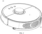
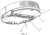
- FIG. 1 and FIG. 2 are schematic view of an intelligent cleaning apparatus according to an embodiment.
- the intelligent cleaning apparatus may include a perception system, a control system (not shown in the FIGs), a driving system, a power system and a human-machine interaction system 9, in addition to a main body 1 and a cleaning system.
- the main parts of the intelligent cleaning apparatus are described in detail below.
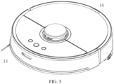
- the main body 1 may include an upper cover, a forward part 13, a backward part 14, and a chassis11, etc.
- the main body 1 is roughly round, especially the forward part 13 and the backward part 14 are approximate circular shaped. It can be understood that, the main body 1 can also have other shapes, including but not limited to an approximate D shape.
- the perception system may include a position determination device disposed above the main body 1, a bumper disposed on the forward part 13 of the main body 1, a cliff sensor 51, an ultrasonic sensor, an infrared sensor, a magnetometer, an accelerometer, a gyroscope, an odometer, and the like. These sensing devices provide various location information and motion status information of the main body 1 to the control system.
- the position determination device may include but not limited to an infrared transmitting and receiving device, a camera, and a laser detection sensor (LDS).
- the cleaning system may include a dry cleaning unit and a wet cleaning unit.
- the wet cleaning unit is a first cleaning unit 2.
- a main function of the wet cleaning unit is to wipe the surface to be cleaned (such as the ground) with a cleaning mop 4 containing cleaning liquid.
- the dry cleaning unit is a second cleaning unit.
- a main function of the dry cleaning unit is to clean particle contaminants on the surface to be cleaned by an equipment such as a cleaning brush.
- the main cleaning function of the dry-cleaning unit is derived from the second cleaning unit including a roller brush 61, a dust container, a fan, an air outlet, and the connecting member between the four parts.
- the roller brush 61 has a certain interference with the ground, sweeps the garbage on the ground and rolls it to the front of the suction port between the roller brush 61 and the dust container. And then the garbage is sucked into the dust container by an air flow generated by the fan and passing through the dust container.
- the dust removal capability of the sweeper can be characterized by DPU (dust pick up efficiency).
- the DPU is influenced by the structure and material of the roller brush 61, influenced by the wind power utilization rate of the air duct formed by the suction port, the dust container, the fan, the air outlet, and the connecting member therebetween, and also influenced by the type and power of the fan.
- the improvement of dust removal capability is more meaningful for energy-limited cleaning robots.
- the improvement of dust removal capability can directly reduce the energy requirements.
- the robot that can clean 80-square-meter ground with a single charge can be evolved to clean 100-square-meter ground or more.
- the battery life will be greatly increased and battery replacement frequency will also decrease. More intuitive and important, the improvement of dust removal capability is the most obvious and important user experience.
- the dry cleaning system may also include a side brush 62 having a rotating shaft.
- the rotating shaft is at an angle relative to the ground.
- the rotating shaft is configured to move the debris into the cleaning area of the roller brush 61, and the rotating shaft is at an angle relative to the ground.
- the first cleaning unit 2 may mainly include a water tank 3, a cleaning mop 4, and the like.
- the water tank 3 serves as the base for carrying other components of the first cleaning unit 2.
- the cleaning mop 4 is detachably disposed on the water tank 3. The liquid in the water tank 3 flows to the cleaning mop 4. The cleaning mop 4 wipes the ground cleaned by the roller brush.
- the driving system is configured to drive the main body 1 and components mounted on the main body 1 to move, for automatic travel and cleaning.
- the driving system may include a drive wheel module.
- the driving system can issue a drive command to manipulate the robot to travel across the ground.
- the drive command is based on distance information and angle information, such as x, y and ⁇ components.
- the drive wheel module can control both the left wheel and the right wheel, in order to control the movement of the machine more precisely.
- the drive wheel module includes a left drive wheel module and a right drive wheel module, respectively.
- the left drive wheel module and the right drive wheel module are arranged along the horizontal axis alignment defined by the main body 1 (symmetrical setting).
- the robot can include one or more driven wheels 72.
- the driven wheels include but not limited to a universal wheel.
- the drive wheel module may include a travel wheel, a drive motor, and a control circuit configured to control the drive motor.
- the drive wheel module can also be connected to a circuit for measuring the drive current and an odometer.
- the drive wheel module can be detachably connected to the main body 1 for easy disassembly and maintenance.
- the drive wheel may have an offset drop suspension system.
- the drive wheel is movably fastened, for example, rotatable attached to the main body 1, and receives a spring bias that is biased downward and away from the main body 1. Spring bias allows the drive wheel to maintain contact and traction with the ground with a certain ground force.
- the robot's cleaning element such as roller brush, etc. also contact the ground with a certain pressure.
- the forward part 13 of the main body 1 can hold the bumper.
- the drive wheel module drives the robot to travel on the ground, and the bumper detects one or more events in the travel path of the robot via a sensor, such as an infrared sensor.
- the robot can control the drive wheel module by events detected by the bumper, such as obstacles and walls, to enable the robot to respond to events, such as moving away from obstacles.
- the control system provided on the circuit board inside the main body 1.
- the control system may include a non-transitory memory and a computing processor.
- the non-transitory memory may include a hard disk, a flash memory or a random access memory.
- the computing processor may include a central processing unit, or an application processor.
- the application processor uses a positioning algorithm, such as SLAM, to map an instant map in the environment in which the robot is located based on the obstacle information fed back by the laser detection sensor.
- the distance information and velocity information fed back by the bumper, the cliff sensor 51, and an ultrasonic sensor, an infrared sensor, a magnetometer, an accelerometer, a gyroscope, an odometer and other sensing device are used to determine the current working state of the sweeper.
- the working state of the sweeping machine may include over the threshold, over the carpet, over the cliff, stuck above or below, dust container full, picked up, etc.
- the application processor gives specific instructions for the next step for different situations.
- the robot is more in line with the requirements of the owner, and provides a better user experience.
- the control system can plan the most efficient cleaning path and cleaning method based on real-time map information drawn by SLAM, which greatly improves the cleaning efficiency of the robot.
- the power system may include a rechargeable battery, such as a nickel-metal hydride battery and a lithium battery.
- the rechargeable battery can be coupled to a charging control circuit, a battery pack charging temperature detecting circuit and a battery under voltage monitoring circuit.
- the charging control circuit, the battery pack charging temperature detecting circuit and the battery under voltage monitoring circuit connected with the control circuit for the single chip microcomputer.
- the host is charged by connecting to the charging pile provided on the side or the lower side of the host.
- the human-machine interaction system 9 includes buttons on the host panel for the user to select the function.
- the human-machine interaction system 9 may further include a display and/or an indicator light and/or a speaker, and the display.
- the indicator light and the speaker show the current state of the machine or the function selection to the user.
- the human-machine interaction system 9 may also include a mobile client program. For path navigation type cleaning apparatus, the mobile client can show the user the map of the apparatus 's environment and the location of the apparatus, which can provide users with more rich and user-friendly functions.
- the robot can travel on the ground by various combinations of movements of the following three mutually perpendicular axes defined by the main body 1: a front and rear axis X (ie, the axis in the direction of the forward part 13 and backward part 14 of main body1), a lateral axis Y (ie, an axis perpendicular to axis X and at a same horizontal plane with the axis X) and a center vertical axis Z (axis perpendicular to the plane formed by axis X and axis Y).
- a front and rear axis X ie, the axis in the direction of the forward part 13 and backward part 14 of main body1
- a lateral axis Y ie, an axis perpendicular to axis X and at a same horizontal plane with the axis X
- a center vertical axis Z axis perpendicular to the plane formed by axis X and axis
- the forward driving direction along the front and rear axis X is indicated as “forward”
- the backward driving direction along the front and rear axis X is indicated as “backward”.
- the lateral axis Y extends along the axis defined by the center point of the drive wheel module 71 between the right wheel and the left wheel of the autonomous cleaning robot.
- the robot can rotate around the Y axis.
- the robot's forward part is tilted upward and the backward part is tilted downward, it is defined as “up”
- the forward part of the robot is tilted downward and the backward part is tilted upward, it is defined as “down”.
- the robot can rotate around the Z axis. In the forward direction of robot, when the robot tilts to the right of the X axis, it is defined as "right turn”, when the robot tilts to the left side of the X axis, it is defined as "left turn”.
- the dust container is mounted in the accommodating cavity by means of buckle and handle.
- the buckle shrinks.
- the buckle extends to a recess of the accommodating cavity that receives the limiting member.
- the pressure in the water tank 3 is equal to or slightly lower than atmospheric pressure. Therefore, the liquid discharge hole does not discharge the liquid without an external force.
- a liquid discharge structure water outlet filter
- the liquid outlet hole is usually equipped with a cleaning mop 4 having water absorption.
- the intelligent cleaning apparatus is configured to discharge the liquid through the liquid outlet hole under the action of suction, when the liquid discharge structure is in conflict with the cleaning mop 4.
- the cleaning mop 4 is slightly interfered with the surface, to make the cleaning mop 4 against the surface, apply a continuous force to the liquid discharge structure, so that the liquid outlet hole can discharge the liquid evenly.
- the charging station is used to charge the intelligent cleaning apparatus.
- the charging station is usually placed somewhere on a plane surface, for example, the floor near a wall or a corner, and the intelligent cleaning apparatus can be moved to the position of the charging station. When the intelligent cleaning apparatus is at the position, the charging station can charge the intelligent cleaning apparatus.
- moisture-proof mat 100 is also provided at the charging station, when the intelligent cleaning apparatus is charged.
- the moisture-proof mat 100 is located below the intelligent cleaning apparatus (ie, the charging location of the intelligent cleaning apparatus is above the moisture-proof mat 100).
- the moisture-proof mat 100 is made of a hard material such as a hard glue, and has good waterproof performance.
- the general outline of the moisture-proof mat 100 matches the shape of the intelligent cleaning apparatus.
- the moisture-proof mat 100 can be connected to the charging station.
- the moisture-proof mat 100 may include an installation unit configured to install the moisture-proof mat to the charging station.
- the installation unit is a notch defined on the edge of the moisture-proof mat.
- the notch is recessed from the edge toward the center of the moisture-proof mat, so as to partially surround the charging station.
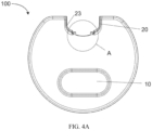
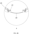
- the shape of the notch 20 matches the shape of the outer peripheral surface of the charging station, thereby making the notch 20 fit within the charging station. In a specific embodiment, and the outer contour of the charging station is inserted into the notch 20.
- the extending direction or the set direction (eg, "horizontal”, “vertical) of the various components is refer to the extending direction or the set direction thereof when the intelligent cleaning system is disposed on a horizontal plane.
- the notch 20 is provided with a buckle 23 for matching the outer peripheral surface of the charging station.
- the buckle 23 extends along the edge of the notch 20 horizontally.
- the buckle 23 may include a first portion extending perpendicular to the extension direction of the moisture-proof mat and a second portion extends from the upper end of the first portion toward the charging station.
- the buckle 23 is able to fasten the edges of the charging station, for example, the edge of the joint on the charging station.
- the first portion is in contact with the side wall of the charging station, and the bottom surface of the second portion is in contact with the top wall of the charging station.
- the notch 20 is also provided with a protrusion 21 extending horizontally toward the charging station, and the charging station is provided with a groove corresponding to the protrusion 21.
- the protrusion 21 can be inserted into the groove, thereby the moisture-proof mat 100 being fixed with the charging station.
- the protrusion may be provided on the charging station, and the groove may be defined on the moisture-proof mat.
- the inner part of notch 20 is a curved part 22, the curved part 22 is positioned between two protrusions 21. It can be understood that, when the curved part 22 is in full contact with the charging station, the moisture-proof mat 100 is installed in place.
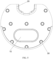
- the moisture-proof mat 100 may include a recess portion 10.
- the recess portion 10 When the intelligent cleaning apparatus is in the charging position, the recess portion 10 is located below the water tank 3. Seen from the top view and the bottom view of the moisture-proof mat 100, the middle part of the recess portion 10 is roughly rectangular, and the ends of the recess portion 10 are semi-circular, the shape of the recess portion 10 corresponds to the shape of the water tank 3.
- the liquid discharge structure at the liquid outlet hole of the water tank 3 is configured to protrude downward from the bottom surface of the water tank 3 by 0.2 to 0.5 mm.
- the distance between the bottom surface of the recess portion 10 and the top surface of the moisture-proof mat 100 is 0.6 - 0.8 mm.
- the moisture-proof mat 100 may further include more than one antiskid device 30 disposed on the bottom of the moisture-proof mat and protruding therefrom.
- the antiskid device 30 has a circular cross section.
- the antiskid device 30 is made of a flexible material.
- the lower end of the antiskid device 30 has a larger diameter than the middle or upper part has, thereby forming a suction cup structure, to secure the moisture-proof mat 100 on a flat surface.
- the antiskid device 30 can be made of transparent and/or waterproof materials, to make the antiskid device 30 have a better appearance. Referring to FIG. 2 , the antiskid devices 30 can be evenly distributed at the bottom of the moisture-proof mat 100.
- a plurality of the antiskid devices 30 are disposed at an edge of the moisture-proof mat 100 away from the end being connected to the charging station, thereby further optimizing the fixing effect of the antiskid device 30.
- the moisture-proof mat 100 has an rounded edge 40, and the side walls and the surface of the moisture-proof mat 100 are connected by the rounded edge 40. Due to the rounded edge 40, the intelligent cleaning apparatus can move onto the moisture-proof mat 100 more conveniently.
- the moisture-proof mat when the intelligent cleaning apparatus is charged by the charging station, the moisture-proof mat is under the intelligent cleaning apparatus, so that the surface for placing the intelligent cleaning apparatus is less susceptible to moisture and damage.
- the moisture-proof mat 100 is detachably connected to the charging station to facilitate installation, disassembly, storage and transportation of the intelligent cleaning system.
Landscapes
- Engineering & Computer Science (AREA)
- Robotics (AREA)
- Mechanical Engineering (AREA)
- Electric Vacuum Cleaner (AREA)
- Charge And Discharge Circuits For Batteries Or The Like (AREA)
- Cleaning Implements For Floors, Carpets, Furniture, Walls, And The Like (AREA)
- Management, Administration, Business Operations System, And Electronic Commerce (AREA)
- Body Washing Hand Wipes And Brushes (AREA)
Claims (10)
- Système de nettoyage intelligent, comprenant :une station de recharge ;un appareil de nettoyage intelligent, équipé d'un réservoir d'eau (3), d'un tampon de nettoyage humide (4) et configuré pour être rechargé par la station de recharge ; etun tapis anti-humidité (100) ;caractérisé par le fait que, le tapis anti-humidité (100) est relié de manière amovible à la station de recharge et comprend :
une unité d'installation, configurée pour installer le tapis anti-humidité (100) sur la station de recharge, dans laquelle au moins une partie du tapis anti-humidité (100) est configurée pour être disposée sous le tampon de nettoyage humide (4), lorsque l'appareil de nettoyage intelligent est chargé par la station de recharge, dans laquelle le tapis anti-humidité (100) est utilisé pour empêcher le liquide dans le réservoir d'eau (3) de s'écouler et d'endommager une surface sur laquelle est placé l'appareil de nettoyage intelligent. - Système de nettoyage intelligent selon la revendication 1, comprenant en outre au moins un dispositif antidérapant (30), disposé sur le fond du tapis anti-humidité (100), où au moins un dispositif antidérapant (30) est fabriqué d'un matériau flexible, et configuré pour faire saillie vers le bas à partir du fond du tapis anti-humidité (100).
- Système de nettoyage intelligent selon la revendication 1 ou 2, comprenant en outre une partie de renfoncement (10), dans lequel la partie de renfoncement (10) est configuré pour être situé en dessous d'une partie de décharge de liquide prévue sur une surface inférieure du tampon de nettoyage humide (4), et une surface supérieure de la partie de renfoncement (10) n'entre pas en contact avec la partie de décharge de liquide, lorsque l'appareil de nettoyage intelligent est chargé par la station de recharge.
- Système de nettoyage intelligent selon l'une quelconque des revendications précédentes, dans lequel, la forme du tapis anti-humidité (100) correspond à la forme de la section transversale de l'appareil de nettoyage intelligent.
- Système de nettoyage intelligent selon l'une quelconque des revendications précédentes, dans lequel la forme du tapis anti-humidité (100) est à peu près ronde avec une encoche.
- Système de nettoyage intelligent selon l'une des revendications précédentes, dans lequel l'unité d'installation comprend une encoche (20) définie sur un bord du tapis anti-humidité (100), l'encoche (20) étant en retrait du bord vers le centre du tapis anti-humidité (100) et configurée pour entourer partiellement la station de recharge.
- Système de nettoyage intelligent selon la revendication 6, dans lequel l'encoche (20) comprend au moins l'un des éléments suivants :une boucle (22), configurée pour être attachée à une surface périphérique extérieure de la station de recharge, la boucle (20) comprenant une première partie s'étendant vers le haut à partir d'une surface inférieure du tapis anti-humidité (100) et une deuxième partie s'étendant à partir d'une extrémité supérieure de la première partie vers la station de recharge,une protubérance (21), configurée pour s'étendre vers la station de recharge et être insérée dans une partie rainurée de la station de recharge , ouune rainure, configurée pour accueillir une partie protubérante de la station de recharge.
- Système de nettoyage intelligent selon l'une des revendications précédentes, dans lequel la surface supérieure du tapis anti-humidité (100) est pourvue d'un bord arrondi (40), faisant face à la direction de l'appareil de nettoyage intelligent se déplaçant vers le tapis anti-humidité (100).
- Système de nettoyage intelligent selon l'une des revendications précédentes, dans lequel l'une d'entre la unité d'installation et la station de recharge comprennent une protubérance, l'autre d'entre la unité d'installation et la station de recharge définissent une rainure, et la protubérance est configurée pour coopérer avec la rainure afin de relier le tapis anti-humidité (100) à la station de recharge.
- Système de nettoyage intelligent selon l'une des revendications précédentes, le tapis anti-humidité (100) comprenant en outre une partie d'évacuation de liquide disposée sur la surface inférieure du tampon de nettoyage humide (4), et la partie d'évacuation de liquide est configurée pour évacuer le liquide contenu dans le tampon de nettoyage humide lorsqu'elle est soumise à une pression.
Applications Claiming Priority (2)
| Application Number | Priority Date | Filing Date | Title |
|---|---|---|---|
| CN201721210564.3U CN208973678U (zh) | 2017-09-19 | 2017-09-19 | 防潮垫和智能清洁系统 |
| PCT/CN2018/105339 WO2019056973A1 (fr) | 2017-09-19 | 2018-09-12 | Tapis résistant à l'humidité et système de nettoyage intelligent |
Publications (3)
| Publication Number | Publication Date |
|---|---|
| EP3684238A1 EP3684238A1 (fr) | 2020-07-29 |
| EP3684238A4 EP3684238A4 (fr) | 2021-08-25 |
| EP3684238B1 true EP3684238B1 (fr) | 2025-05-28 |
Family
ID=65810636
Family Applications (1)
| Application Number | Title | Priority Date | Filing Date |
|---|---|---|---|
| EP18859306.5A Active EP3684238B1 (fr) | 2017-09-19 | 2018-09-12 | Tapis résistant à l'humidité et système de nettoyage intelligent |
Country Status (9)
| Country | Link |
|---|---|
| US (1) | US11659972B2 (fr) |
| EP (1) | EP3684238B1 (fr) |
| CN (1) | CN208973678U (fr) |
| DE (1) | DE202018006994U1 (fr) |
| DK (1) | DK3684238T3 (fr) |
| ES (1) | ES3039558T3 (fr) |
| FI (1) | FI3684238T3 (fr) |
| TW (1) | TWM579002U (fr) |
| WO (1) | WO2019056973A1 (fr) |
Families Citing this family (11)
| Publication number | Priority date | Publication date | Assignee | Title |
|---|---|---|---|---|
| CN118285699A (zh) | 2019-09-05 | 2024-07-05 | 北京石头创新科技有限公司 | 一种清洁机器人及其控制方法 |
| TWD209974S (zh) * | 2019-09-05 | 2021-02-21 | 大陸商北京石頭世紀科技股份有限公司 | 托板 |
| CN112168093B (zh) * | 2019-10-22 | 2022-04-29 | 追觅创新科技(苏州)有限公司 | 一种用于扫地机的控制方法及控制器 |
| CN114451822A (zh) * | 2020-11-09 | 2022-05-10 | 好样科技有限公司 | 具有防潮垫的充电模组及清洁系统 |
| USD999470S1 (en) | 2021-02-10 | 2023-09-19 | Beijing Roborock Technology Co., Ltd. | Supporting plate for cleaning pad for robotic vacuum cleaner |
| CN113100675A (zh) * | 2021-04-06 | 2021-07-13 | 珠海格力电器股份有限公司 | 拖布移除提醒方法、装置及清洁机器人系统 |
| CN113116240B (zh) * | 2021-04-06 | 2022-09-09 | 珠海格力电器股份有限公司 | 拖布移除提醒方法、装置及清洁机器人 |
| CN114794982A (zh) * | 2022-04-12 | 2022-07-29 | 北京石头世纪科技股份有限公司 | 清洁机器人系统 |
| CN116942021B (zh) * | 2022-10-31 | 2025-11-14 | 深圳以内创新科技有限公司 | 清洁设备和清洁系统 |
| JP1788034S (ja) * | 2023-03-15 | 2024-12-27 | 移動掃除ロボット用クリーニングパッド | |
| CN116869427A (zh) * | 2023-04-28 | 2023-10-13 | 深圳以内创新科技有限公司 | 停靠基站以及清洁系统 |
Family Cites Families (28)
| Publication number | Priority date | Publication date | Assignee | Title |
|---|---|---|---|---|
| US6295658B1 (en) * | 1997-11-24 | 2001-10-02 | Matthew Jenkins | Floor-mat system |
| JP2004350826A (ja) * | 2003-05-28 | 2004-12-16 | Matsushita Electric Ind Co Ltd | 電気掃除機 |
| DE10357637A1 (de) * | 2003-12-10 | 2005-07-07 | Vorwerk & Co. Interholding Gmbh | Selbstfahrendes oder zu verfahrendes Kehrgerät sowie Kombination eines Kehrgeräts mit einer Basisstation |
| US20080104783A1 (en) * | 2006-10-04 | 2008-05-08 | Scott Crawford | Dust mop |
| DE102008018511B4 (de) | 2008-04-12 | 2015-10-08 | Vorwerk & Co. Interholding Gmbh | Vorrichtung zur Abreinigung eines Boden-Reinigungsgeräts sowie Kombination eines solchen Geräts mit einer Vorrichtung |
| US8961695B2 (en) * | 2008-04-24 | 2015-02-24 | Irobot Corporation | Mobile robot for cleaning |
| KR101483541B1 (ko) * | 2010-07-15 | 2015-01-19 | 삼성전자주식회사 | 로봇청소기, 메인터넌스 스테이션 그리고 이들을 가지는 청소시스템 |
| US9178370B2 (en) * | 2012-12-28 | 2015-11-03 | Irobot Corporation | Coverage robot docking station |
| KR102122861B1 (ko) * | 2013-06-17 | 2020-06-29 | 삼성전자주식회사 | 로봇청소기 및 그 제어 방법 |
| KR102083188B1 (ko) * | 2013-07-29 | 2020-03-02 | 삼성전자주식회사 | 청소 로봇 및 그 제어 방법 |
| US9504367B2 (en) * | 2013-11-20 | 2016-11-29 | Samsung Electronics Co., Ltd. | Cleaning robot and method for controlling the same |
| KR20150073592A (ko) * | 2013-12-23 | 2015-07-01 | 서울바이오시스 주식회사 | 자외선 발광 다이오드를 갖는 로봇 물걸레 청소기 시스템 |
| KR20150073735A (ko) | 2013-12-23 | 2015-07-01 | 서울바이오시스 주식회사 | 충전장치가 구비된 로봇 물걸레 청소기 및 그 구동 방법 |
| KR102103420B1 (ko) | 2013-12-30 | 2020-05-29 | 삼성전자주식회사 | 패드 교체 장치, 이를 포함하는 청소기 및 청소기 시스템 |
| CN104586324A (zh) | 2015-01-16 | 2015-05-06 | 惠州市鑫沛科技有限公司 | 实现自动导航、擦地、充电和抹布清洗的智能清洁机器人 |
| US9265396B1 (en) * | 2015-03-16 | 2016-02-23 | Irobot Corporation | Autonomous floor cleaning with removable pad |
| CN106137045B (zh) * | 2015-08-21 | 2018-11-06 | 深圳市智意科技有限公司 | 家用扫地机的清洁箱结构 |
| KR101678443B1 (ko) * | 2015-09-23 | 2016-12-06 | 엘지전자 주식회사 | 로봇 청소기 |
| CN205306905U (zh) | 2015-10-16 | 2016-06-15 | 东莞缔奇智能股份有限公司 | 地面清洁机器人 |
| CN205911779U (zh) * | 2016-07-06 | 2017-01-25 | 永嘉县金诚贸易有限公司 | 一种r8全自动吸尘器用充电座 |
| CN106166050A (zh) * | 2016-07-26 | 2016-11-30 | 广东宝乐机器人股份有限公司 | 一种擦地机器人 |
| CN106264342B (zh) * | 2016-08-23 | 2020-04-14 | 北京小米移动软件有限公司 | 清洁机器人及其控制方法 |
| CN206211589U (zh) * | 2016-11-14 | 2017-05-31 | 宁波洒哇地咔电器有限公司 | 一种拖地机多功能充电座 |
| CN106955062B (zh) | 2017-03-10 | 2020-06-30 | 深圳云峯智能科技有限公司 | 一种智能清洁机器人 |
| US10383499B2 (en) * | 2017-08-31 | 2019-08-20 | Irobot Corporation | Wet robot docking station |
| US11274929B1 (en) * | 2017-10-17 | 2022-03-15 | AI Incorporated | Method for constructing a map while performing work |
| US11730329B2 (en) * | 2019-12-06 | 2023-08-22 | Bissell Inc. | Autonomous floor cleaner and docking station |
| US11930993B2 (en) * | 2020-02-10 | 2024-03-19 | Matic Robots, Inc. | Waste bag with absorbent dispersion sachet |
-
2017
- 2017-09-19 CN CN201721210564.3U patent/CN208973678U/zh active Active
-
2018
- 2018-09-10 TW TW107212338U patent/TWM579002U/zh unknown
- 2018-09-12 FI FIEP18859306.5T patent/FI3684238T3/fi active
- 2018-09-12 DE DE202018006994.9U patent/DE202018006994U1/de active Active
- 2018-09-12 US US16/764,320 patent/US11659972B2/en active Active
- 2018-09-12 EP EP18859306.5A patent/EP3684238B1/fr active Active
- 2018-09-12 WO PCT/CN2018/105339 patent/WO2019056973A1/fr not_active Ceased
- 2018-09-12 DK DK18859306.5T patent/DK3684238T3/da active
- 2018-09-12 ES ES18859306T patent/ES3039558T3/es active Active
Also Published As
| Publication number | Publication date |
|---|---|
| ES3039558T3 (en) | 2025-10-22 |
| EP3684238A4 (fr) | 2021-08-25 |
| FI3684238T3 (fi) | 2025-08-06 |
| DE202018006994U1 (de) | 2025-06-23 |
| CN208973678U (zh) | 2019-06-14 |
| US20210106202A1 (en) | 2021-04-15 |
| US11659972B2 (en) | 2023-05-30 |
| DK3684238T3 (da) | 2025-06-30 |
| EP3684238A1 (fr) | 2020-07-29 |
| WO2019056973A1 (fr) | 2019-03-28 |
| TWM579002U (zh) | 2019-06-11 |
Similar Documents
| Publication | Publication Date | Title |
|---|---|---|
| EP3684238B1 (fr) | Tapis résistant à l'humidité et système de nettoyage intelligent | |
| EP3690591B1 (fr) | Robot mobile autonome et son procédé de recherche de station de recharge, appareil de commande et système de nettoyage intelligent | |
| EP4011266B1 (fr) | Structure de scellement et appareil de nettoyage intelligent | |
| TWI789624B (zh) | 一種智慧清潔設備 | |
| TWI689801B (zh) | 自主移動機器人及其尋樁方法、控制裝置以及智能清潔系統 | |
| EP3689214B1 (fr) | Réservoir de stockage de liquide, appareil de nettoyage intelligent et système de nettoyage intelligent | |
| AU2020341965B2 (en) | Cleaning assembly and smart cleaning device | |
| EP4011265B1 (fr) | Bouchon opturateur et dispositif de nettoyage intelligent | |
| CN211674026U (zh) | 清洁机器人及应用于清洁机器人的供水机构 | |
| CN210931185U (zh) | 一种智能清洁设备 | |
| CN210931184U (zh) | 一种清洁组件及智能清洁设备 | |
| CN212261283U (zh) | 清洁机器人及应用于清洁机器人的储水箱 |
Legal Events
| Date | Code | Title | Description |
|---|---|---|---|
| STAA | Information on the status of an ep patent application or granted ep patent |
Free format text: STATUS: THE INTERNATIONAL PUBLICATION HAS BEEN MADE |
|
| PUAI | Public reference made under article 153(3) epc to a published international application that has entered the european phase |
Free format text: ORIGINAL CODE: 0009012 |
|
| STAA | Information on the status of an ep patent application or granted ep patent |
Free format text: STATUS: REQUEST FOR EXAMINATION WAS MADE |
|
| 17P | Request for examination filed |
Effective date: 20200417 |
|
| AK | Designated contracting states |
Kind code of ref document: A1 Designated state(s): AL AT BE BG CH CY CZ DE DK EE ES FI FR GB GR HR HU IE IS IT LI LT LU LV MC MK MT NL NO PL PT RO RS SE SI SK SM TR |
|
| AX | Request for extension of the european patent |
Extension state: BA ME |
|
| DAV | Request for validation of the european patent (deleted) | ||
| DAX | Request for extension of the european patent (deleted) | ||
| A4 | Supplementary search report drawn up and despatched |
Effective date: 20210726 |
|
| RIC1 | Information provided on ipc code assigned before grant |
Ipc: A47L 11/28 20060101AFI20210720BHEP |
|
| STAA | Information on the status of an ep patent application or granted ep patent |
Free format text: STATUS: EXAMINATION IS IN PROGRESS |
|
| 17Q | First examination report despatched |
Effective date: 20230426 |
|
| GRAP | Despatch of communication of intention to grant a patent |
Free format text: ORIGINAL CODE: EPIDOSNIGR1 |
|
| STAA | Information on the status of an ep patent application or granted ep patent |
Free format text: STATUS: GRANT OF PATENT IS INTENDED |
|
| INTG | Intention to grant announced |
Effective date: 20241219 |
|
| GRAS | Grant fee paid |
Free format text: ORIGINAL CODE: EPIDOSNIGR3 |
|
| GRAA | (expected) grant |
Free format text: ORIGINAL CODE: 0009210 |
|
| STAA | Information on the status of an ep patent application or granted ep patent |
Free format text: STATUS: THE PATENT HAS BEEN GRANTED |
|
| AK | Designated contracting states |
Kind code of ref document: B1 Designated state(s): AL AT BE BG CH CY CZ DE DK EE ES FI FR GB GR HR HU IE IS IT LI LT LU LV MC MK MT NL NO PL PT RO RS SE SI SK SM TR |
|
| REG | Reference to a national code |
Ref country code: GB Ref legal event code: FG4D |
|
| REG | Reference to a national code |
Ref country code: CH Ref legal event code: EP |
|
| REG | Reference to a national code |
Ref country code: IE Ref legal event code: FG4D Ref country code: DE Ref legal event code: R096 Ref document number: 602018082306 Country of ref document: DE |
|
| REG | Reference to a national code |
Ref country code: DK Ref legal event code: T3 Effective date: 20250627 |
|
| REG | Reference to a national code |
Ref country code: FI Ref legal event code: FGE |
|
| REG | Reference to a national code |
Ref country code: NL Ref legal event code: FP |
|
| REG | Reference to a national code |
Ref country code: SE Ref legal event code: TRGR |
|
| PGFP | Annual fee paid to national office [announced via postgrant information from national office to epo] |
Ref country code: FI Payment date: 20250930 Year of fee payment: 8 |
|
| PGFP | Annual fee paid to national office [announced via postgrant information from national office to epo] |
Ref country code: DK Payment date: 20250923 Year of fee payment: 8 Ref country code: DE Payment date: 20250924 Year of fee payment: 8 |
|
| REG | Reference to a national code |
Ref country code: LT Ref legal event code: MG9D |
|
| PG25 | Lapsed in a contracting state [announced via postgrant information from national office to epo] |
Ref country code: GR Free format text: LAPSE BECAUSE OF FAILURE TO SUBMIT A TRANSLATION OF THE DESCRIPTION OR TO PAY THE FEE WITHIN THE PRESCRIBED TIME-LIMIT Effective date: 20250829 |
|
| PG25 | Lapsed in a contracting state [announced via postgrant information from national office to epo] |
Ref country code: PL Free format text: LAPSE BECAUSE OF FAILURE TO SUBMIT A TRANSLATION OF THE DESCRIPTION OR TO PAY THE FEE WITHIN THE PRESCRIBED TIME-LIMIT Effective date: 20250528 |
|
| PGFP | Annual fee paid to national office [announced via postgrant information from national office to epo] |
Ref country code: TR Payment date: 20250825 Year of fee payment: 8 Ref country code: NL Payment date: 20250927 Year of fee payment: 8 Ref country code: IT Payment date: 20250929 Year of fee payment: 8 |
|
| PG25 | Lapsed in a contracting state [announced via postgrant information from national office to epo] |
Ref country code: BG Free format text: LAPSE BECAUSE OF FAILURE TO SUBMIT A TRANSLATION OF THE DESCRIPTION OR TO PAY THE FEE WITHIN THE PRESCRIBED TIME-LIMIT Effective date: 20250528 |
|
| PGFP | Annual fee paid to national office [announced via postgrant information from national office to epo] |
Ref country code: GB Payment date: 20250927 Year of fee payment: 8 |
|
| PGFP | Annual fee paid to national office [announced via postgrant information from national office to epo] |
Ref country code: FR Payment date: 20250926 Year of fee payment: 8 |
|
| PGFP | Annual fee paid to national office [announced via postgrant information from national office to epo] |
Ref country code: SE Payment date: 20250927 Year of fee payment: 8 |
|
| PG25 | Lapsed in a contracting state [announced via postgrant information from national office to epo] |
Ref country code: RS Free format text: LAPSE BECAUSE OF FAILURE TO SUBMIT A TRANSLATION OF THE DESCRIPTION OR TO PAY THE FEE WITHIN THE PRESCRIBED TIME-LIMIT Effective date: 20250828 |
|
| PG25 | Lapsed in a contracting state [announced via postgrant information from national office to epo] |
Ref country code: IS Free format text: LAPSE BECAUSE OF FAILURE TO SUBMIT A TRANSLATION OF THE DESCRIPTION OR TO PAY THE FEE WITHIN THE PRESCRIBED TIME-LIMIT Effective date: 20250928 |
|
| PG25 | Lapsed in a contracting state [announced via postgrant information from national office to epo] |
Ref country code: LV Free format text: LAPSE BECAUSE OF FAILURE TO SUBMIT A TRANSLATION OF THE DESCRIPTION OR TO PAY THE FEE WITHIN THE PRESCRIBED TIME-LIMIT Effective date: 20250528 |
|
| REG | Reference to a national code |
Ref country code: AT Ref legal event code: MK05 Ref document number: 1798134 Country of ref document: AT Kind code of ref document: T Effective date: 20250528 |
|
| PGFP | Annual fee paid to national office [announced via postgrant information from national office to epo] |
Ref country code: NO Payment date: 20251001 Year of fee payment: 8 |
|
| PG25 | Lapsed in a contracting state [announced via postgrant information from national office to epo] |
Ref country code: AT Free format text: LAPSE BECAUSE OF FAILURE TO SUBMIT A TRANSLATION OF THE DESCRIPTION OR TO PAY THE FEE WITHIN THE PRESCRIBED TIME-LIMIT Effective date: 20250528 Ref country code: SM Free format text: LAPSE BECAUSE OF FAILURE TO SUBMIT A TRANSLATION OF THE DESCRIPTION OR TO PAY THE FEE WITHIN THE PRESCRIBED TIME-LIMIT Effective date: 20250528 |
|
| PG25 | Lapsed in a contracting state [announced via postgrant information from national office to epo] |
Ref country code: CZ Free format text: LAPSE BECAUSE OF FAILURE TO SUBMIT A TRANSLATION OF THE DESCRIPTION OR TO PAY THE FEE WITHIN THE PRESCRIBED TIME-LIMIT Effective date: 20250528 |
|
| PG25 | Lapsed in a contracting state [announced via postgrant information from national office to epo] |
Ref country code: EE Free format text: LAPSE BECAUSE OF FAILURE TO SUBMIT A TRANSLATION OF THE DESCRIPTION OR TO PAY THE FEE WITHIN THE PRESCRIBED TIME-LIMIT Effective date: 20250528 |
|
| PG25 | Lapsed in a contracting state [announced via postgrant information from national office to epo] |
Ref country code: RO Free format text: LAPSE BECAUSE OF FAILURE TO SUBMIT A TRANSLATION OF THE DESCRIPTION OR TO PAY THE FEE WITHIN THE PRESCRIBED TIME-LIMIT Effective date: 20250528 Ref country code: SK Free format text: LAPSE BECAUSE OF FAILURE TO SUBMIT A TRANSLATION OF THE DESCRIPTION OR TO PAY THE FEE WITHIN THE PRESCRIBED TIME-LIMIT Effective date: 20250528 |
|
| PGFP | Annual fee paid to national office [announced via postgrant information from national office to epo] |
Ref country code: ES Payment date: 20251001 Year of fee payment: 8 |
|
| REG | Reference to a national code |
Ref country code: DE Ref legal event code: R097 Ref document number: 602018082306 Country of ref document: DE |
|
| PLBE | No opposition filed within time limit |
Free format text: ORIGINAL CODE: 0009261 |
|
| STAA | Information on the status of an ep patent application or granted ep patent |
Free format text: STATUS: NO OPPOSITION FILED WITHIN TIME LIMIT |
|
| REG | Reference to a national code |
Ref country code: CH Ref legal event code: L10 Free format text: ST27 STATUS EVENT CODE: U-0-0-L10-L00 (AS PROVIDED BY THE NATIONAL OFFICE) Effective date: 20260409 |
|
| REG | Reference to a national code |
Ref country code: CH Ref legal event code: H13 Free format text: ST27 STATUS EVENT CODE: U-0-0-H10-H13 (AS PROVIDED BY THE NATIONAL OFFICE) Effective date: 20260425 |