EP3684538B1 - Source de courant de soudage ayant un dispositif de refroidissement - Google Patents
Source de courant de soudage ayant un dispositif de refroidissement Download PDFInfo
- Publication number
- EP3684538B1 EP3684538B1 EP18785826.1A EP18785826A EP3684538B1 EP 3684538 B1 EP3684538 B1 EP 3684538B1 EP 18785826 A EP18785826 A EP 18785826A EP 3684538 B1 EP3684538 B1 EP 3684538B1
- Authority
- EP
- European Patent Office
- Prior art keywords
- power source
- welding power
- housing
- welding
- inductance
- Prior art date
- Legal status (The legal status is an assumption and is not a legal conclusion. Google has not performed a legal analysis and makes no representation as to the accuracy of the status listed.)
- Active
Links
Images


Classifications
-
- B—PERFORMING OPERATIONS; TRANSPORTING
- B23—MACHINE TOOLS; METAL-WORKING NOT OTHERWISE PROVIDED FOR
- B23K—SOLDERING OR UNSOLDERING; WELDING; CLADDING OR PLATING BY SOLDERING OR WELDING; CUTTING BY APPLYING HEAT LOCALLY, e.g. FLAME CUTTING; WORKING BY LASER BEAM
- B23K9/00—Arc welding or cutting
- B23K9/10—Other electric circuits therefor; Protective circuits; Remote controls
- B23K9/1006—Power supply
-
- B—PERFORMING OPERATIONS; TRANSPORTING
- B23—MACHINE TOOLS; METAL-WORKING NOT OTHERWISE PROVIDED FOR
- B23K—SOLDERING OR UNSOLDERING; WELDING; CLADDING OR PLATING BY SOLDERING OR WELDING; CUTTING BY APPLYING HEAT LOCALLY, e.g. FLAME CUTTING; WORKING BY LASER BEAM
- B23K37/00—Auxiliary devices or processes, not specially adapted for a procedure covered by only one of the other main groups of this subclass
- B23K37/003—Cooling means for welding or cutting
-
- B—PERFORMING OPERATIONS; TRANSPORTING
- B23—MACHINE TOOLS; METAL-WORKING NOT OTHERWISE PROVIDED FOR
- B23K—SOLDERING OR UNSOLDERING; WELDING; CLADDING OR PLATING BY SOLDERING OR WELDING; CUTTING BY APPLYING HEAT LOCALLY, e.g. FLAME CUTTING; WORKING BY LASER BEAM
- B23K9/00—Arc welding or cutting
- B23K9/32—Accessories
-
- H—ELECTRICITY
- H05—ELECTRIC TECHNIQUES NOT OTHERWISE PROVIDED FOR
- H05K—PRINTED CIRCUITS; CASINGS OR CONSTRUCTIONAL DETAILS OF ELECTRIC APPARATUS; MANUFACTURE OF ASSEMBLAGES OF ELECTRICAL COMPONENTS
- H05K7/00—Constructional details common to different types of electric apparatus
- H05K7/20—Modifications to facilitate cooling, ventilating, or heating
- H05K7/2089—Modifications to facilitate cooling, ventilating, or heating for power electronics, e.g. for inverters for controlling motor
- H05K7/20909—Forced ventilation, e.g. on heat dissipaters coupled to components
- H05K7/20918—Forced ventilation, e.g. on heat dissipaters coupled to components the components being isolated from air flow, e.g. hollow heat sinks, wind tunnels or funnels
Definitions
- the invention relates to a welding power source for supplying an electrical welding circuit with electrical current and electrical voltage for carrying out an electrical welding process, wherein the welding power source is provided with a power conditioning device for conditioning the electrical current supplied to the welding power source for suitability in an electrical welding process, furthermore two pole contact devices are provided on a housing of the welding power source, each of which protrudes from the housing, and the welding power source is provided with a cooling device with which thermal waste heat released by the welding power source can be dissipated.
- the present invention is of particular importance for the various processes and welding circuit devices of arc welding. These are based on the development of heat from an electric arc between a welding electrode and a workpiece on which welding is to be carried out. The development of heat can melt the material(s) to be welded locally.
- a protective gas is supplied to the area of the arc for this purpose, on the one hand to enable an ionized atmosphere between the welding electrode and the workpiece that reduces resistance and on the other hand to prevent oxidation of the welding electrode and the workpiece.
- an active gas or a mixed form can also be supplied, which serves for the reaction.
- Electrodes can also be provided that do not require an external gas supply, since the substances required for this are integrated in the electrodes and are released when the electrodes melt.
- Arc welding systems or arc welding circuits are each provided with a welding power source to provide the required electrical current and voltage, to which the welding torch of the arc welding system must be electrically connected so that current can be supplied to the respective arc welding point and a voltage can be applied to it. Since a high energy requirement is required to generate the conditions prevailing at the process point, welding power sources must provide direct current or alternating current with high current values (collectively referred to as welding current). In industrial use, this is generated from three-phase current that is connected to the welding power source. The welding power sources use inductors and power electronics contained in the welding power source to transform the three-phase current present on the input side into welding current that is suitable for arc welding.
- the WO 01/78932 A1 describes a welding power source with an induction, which is arranged in a substantially cubic housing and can be closed with a cover of the housing.
- the induction is located inside the housing in a heat-conducting liquid. Cooling fins are provided on the outside of the housing, through which heat given off by the cooling liquid to the housing is to be dissipated.
- a welding power source which has a substantially closed housing.
- the housing is divided into several chambers by partitions.
- heat-generating electronic components are located on one side of a partition.
- Cooling fins are arranged on the other side of the partition, past which air is moved by a fan, in order to absorb heat from the cooling fins and dissipate it from openings in the housing.
- the US 2017/0150654 A1 relates to a power converter for industrial machines.
- This document discloses a power converter with a housing that has a first space S1 and a second space.
- the first space and the second space are separated from one another by a partition wall.
- In the first space S1 there is a circuit arrangement for power conversion.
- the circuit arrangement rests against the partition wall in the first space.
- In the second space there is a channel for coolant, with which the circuit arrangement in the first space is cooled.
- Cooling fins for dissipating the heat coming from the circuit arrangement are arranged on an inner side of the housing of the second space.
- electric capacitors protrude from the first space into the second space, which is open at the back.
- the invention is therefore based on the object of providing a welding power source of the type mentioned at the beginning, in which, despite sufficient cooling of the electrical components, it is possible to make the housing of the welding power source smaller than before.
- an inductance device of the current transformation device is arranged in a heat sink and the heat sink is arranged together with the inductance device on an outside of the housing. It has surprisingly been shown within the scope of the invention that by moving the cooling device and the inductance device from the interior of the housing to an outside of the housing, the housing can be reduced in size by more than just the volume of the cooling device and the inductance device. In the case of heat sinks and inductance devices arranged within the housing space, a minimum distance must generally be maintained between electronic components also arranged in the housing and the inductance device, such as the transformer, in order to avoid excessive heating.
- the housing can be made significantly smaller than would be the case if the volume were reduced by the components no longer provided within the housing according to the invention.
- the measure according to the invention also has the advantage that the waste heat can be dissipated particularly quickly and effectively into the environment, since there is no risk of heat build-up or of the warm air being difficult to dissipate from the housing.
- the inductance device is provided with at least one transformer which is arranged inside the heat sink.
- the heat sink and the inductance device can be arranged in a particularly space-saving manner and, at the same time, the thermal heat loss generated by the inductance device can be dissipated to the environment particularly effectively.
- the inductance device can be safely protected from damage by arranging a cover, in particular a flow guide plate, over the inductance device.
- a cover in particular a flow guide plate
- the cover in an intended position of use of the welding power source, the cover is arranged at a distance from an intended installation surface of the welding power source and the inductance device in an area with its greatest distance, so that an opening is formed between the cover and the inductance device, from which warm air can flow out.
- the heat sink is arranged on an outside of a housing rear wall.
- the rear of the housing is particularly suitable for arranging the heat sink and the inductance device, since here, through recesses in the rear wall, wiring of the inductance device to electronic components arranged in the housing can be achieved over a particularly short distance.
- particularly good and rapid heat dissipation can be achieved by having cooling fins of the heat sink arranged at a distance from one another that run at least essentially vertically. This makes it possible to use the convection that occurs naturally to dissipate heat in a particularly advantageous manner. Heated air can thus rise unhindered between the cooling fins in the area of the heat sink and thus flow essentially in a vertical direction.
- the heat sink arranged outside the housing is preferably provided with a recess in the area of its cooling fins, through which several cooling fins are interrupted, wherein the recess is provided for arranging the inductance device in the heat sink.
- the inductance device can thus preferably be inserted into the recess of the cooling device from a side facing away from the housing.
- the top of the heat sink should also advantageously be designed in such a way that the outflowing air can escape from the heat sink as unhindered as possible.
- the top of the heat sink should therefore be as free of a cover as possible.
- the welding power source is provided with two or more heat sinks placed on an outer side of the housing of the welding power source, wherein each of these heat sinks has at least one inductance device and can be designed in one of the ways described above.
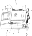
- a welding power source 1 is shown, with which electrical current and an electrical voltage are made available for carrying out arc welding processes using an arc welding torch (not shown in detail).
- the welding power source 1 contains a control device with an operating panel 2, with which parameters of the arc welding process to be carried out can be set and the welding process can be controlled.
- the welding power source 1 can be used to carry out, for example, MIG/MAG or also TIG, plasma, electrode and all other arc welding processes or high-current applications.
- other arc welding and cutting processes can also be carried out with the welding power source 1.
- Two pole contact devices 5, 6 protrude from a housing 4 of the welding power source 1, each of which is intended for the connection of a welding power cable 3.
- the upper section 4a of the housing 4 protrudes on both sides of the housing in relation to the narrow front part 130 of the T-shape of the lower housing section 4b.
- the upper housing section 4a has a width which corresponds at least approximately to the width of the rear, wider part 131 of the lower housing section 4b.
- This configuration results in an area of the upper housing section 4a on each of the sides of the housing 4 in which an underside 7 of the protruding part of the upper housing section 4a is covered by a housing cover, here a housing sheet, and this is freely accessible.
- a housing cover here a housing sheet
- These two areas of the underside 7 of the upper housing section 4a are rectangular in the exemplary embodiment and are freely accessible from the front and from one side of the housing 4.
- These two areas of the underside 7 of the upper housing section 4a are separated from one another by the narrow part of the T-shape of the lower housing section.
- One of the two pole contact devices 5, 6 is arranged on each of the two areas of the underside 7 of the upper housing section 4a, so that only one of the pole contact devices 5, 6 is located on each of these two areas.
- the two pole contact devices 5, 6 thus protrude from the housing 4 of the preferred welding power source 1 according to the invention on the underside 7 of the upper housing section 4a.
- the housing 4 of the welding power source is arranged on a two-part mounting element 9, with which the housing can be placed on a surface.
- a box-shaped and cuboid-shaped heat sink 11 is located on the rear side 10 of the housing 4.
- the heat sink 11 extends essentially over the entire height of the housing 4 and has two at least essentially vertical side walls 12, 13, which are connected to one another by means of cross braces 14, 15.
- a plurality of cooling fins 16 are arranged between the side walls.
- the cooling fins 16 are parallel to the side walls 12, 13 and thus also at least essentially perpendicular to the housing rear wall 21 and also vertically aligned.
- the alignment of the cooling fins corresponds to the self-adjusting heat convection or flow direction of heated air.
- the length of the cooling fins 16, which are essentially of equal length, corresponds essentially to the length of the side walls 12, 13.
- the heat sink 11 is closed off from the housing rear wall 21 of the housing by means of a rear wall 18.
- FIG. 5 The exploded view of Fig. 5 It can be seen that the rear side 10 of the housing 4 of the welding power source 1 is provided with a housing rear wall 21 which is provided with a rectangular recess 22.
- the shape and size of the recess 22 essentially corresponds to the shape of the heat sink 11.
- the heat sink 11 can be attached to the rear wall 21 of the housing 4 by means of a frame 23 and screw connections.
- the recess 22 of the housing rear wall 21 can be completely closed with the rear wall 18 of the heat sink 11 shown in Fig. 6.
- the aluminum cooling fins 16 arranged in this area are provided with an elongated rectangular recess 25, which can be achieved, for example, by milling.
- An inductance device 26 is arranged in the recess 25, which corresponds approximately to the elongated cuboid shape of the recess 25.
- the inductance device 26 contains at least one transformer and, if necessary, one or more further inductors.
- the at least one transformer is encased in a plastic compound to improve heat dissipation.
- the resulting cuboid block of the inductance device 26 is inserted into the recess 25 of the cooling fins and fastened to the rear wall 18.
- Electrical connections 27 of the inductance device 26 are guided through one or more through-recesses through the rear wall 18 in order to be electrically connected to electronic components (not shown in detail) within the housing.
- the inductance device covers all of the through-holes provided for this purpose in the rear wall 18. Heat-emitting electronic components can be arranged on the inside of the housing on the rear wall 18.
- a fan device designed as a fan cassette 29 can optionally be arranged above the inductance device.
- the fan device can be provided with one or more electrically driven fans, wherein the air flow generated by the at least one fan of the fan cassette 29 is directed essentially perpendicularly towards the inductance device 26 and the cooling fins arranged in this area.
- the fan cassette 29 only covers part of the cooling fins.
- a cover 30 acting as a protective and baffle plate can be arranged on the fan device or cassette 29, with which a section of the inductance device 26 protruding beyond the fan device can be covered.
- the cover 30 can be arranged at a distance from the inductance device, while it is bent on both sides in the direction of the inductance device.
- the cover 30 can thus also have the function of forming an upwardly directed flow channel by means of which air heated by the inductance device can flow upwards.
Landscapes
- Engineering & Computer Science (AREA)
- Physics & Mathematics (AREA)
- Mechanical Engineering (AREA)
- Microelectronics & Electronic Packaging (AREA)
- Plasma & Fusion (AREA)
- Optics & Photonics (AREA)
- Thermal Sciences (AREA)
- Arc Welding Control (AREA)
Claims (11)
- Source de courant de soudage (1) pour l'alimentation d'un circuit électrique de soudage en courant électrique et en tension électrique pour la mise en oeuvre d'un procédé de soudage électrique, la source de courant de soudage (1) étant pourvue d'un dispositif de transformation de courant pour la préparation du courant électrique amené à la source de courant de soudage (1) pour une aptitude dans un procédé de soudage électrique, en outre, deux dispositifs de contact polaire (5, 6) sont prévus sur un boîtier (4) de la source de courant de soudage (1), lesquels font respectivement saillie hors du boîtier (4), et la source de courant de soudage (1) est pourvue d'un dispositif de refroidissement avec lequel la chaleur de perte thermique libérée par la source de courant de soudage (1) peut être évacuée,
caractérisé en ce que
un dispositif d'inductance (26), présentant au moins un transformateur ou une autre inductance, du dispositif de transformation du courant est disposé dans un corps de refroidissement (11) du dispositif de refroidissement et le corps de refroidissement (11) est disposé, conjointement avec le dispositif d'inductance (26), sur un côté extérieur du boîtier (4) de la source de courant de soudage (1). - Source de courant de soudage selon la revendication 1, caractérisée en ce que le dispositif de refroidissement est disposé sur un côté extérieur d'une paroi arrière (21) du boîtier.
- Source de courant de soudage selon l'une des deux revendications précédentes, caractérisée en ce qu'un dispositif de ventilation est disposé sur le dispositif de refroidissement, sur le côté du dispositif de refroidissement qui est opposé au côté extérieur du boîtier.
- Source de courant de soudage selon l'une des revendications précédentes, caractérisée en ce que le dispositif d'inductance (26) est pourvu d'au moins un transformateur et d'au moins une autre inductance qui est disposée à l'intérieur d'un corps de refroidissement (11) du dispositif de refroidissement.
- Source de courant de soudage selon l'une des revendications précédentes, caractérisée en ce que le dispositif de refroidissement est pourvu d'ailettes de refroidissement (16), de préférence d'ailettes de refroidissement (16) orientées au moins essentiellement verticalement et disposées à distance les unes des autres
- Source de courant de soudage selon l'une des revendications précédentes, caractérisée en ce qu'un couvercle (30), en particulier une tôle de guidage d'écoulement, est disposé au-dessus du dispositif d'inductance, qui.
- Source de courant de soudage selon l'une des revendications précédentes, caractérisée en ce que la au moins une inductance, en particulier un transformateur, est coulée dans une masse de matière plastique.
- Source de courant de soudage selon l'une des revendications précédentes, caractérisée en ce que le dispositif de refroidissement est pourvu d'une paroi arrière avec laquelle un évidement d'une paroi arrière (21) du boîtier est fermé.
- Source de courant de soudage selon la revendication 8, caractérisée en ce que des composants électroniques de la source de courant de soudage (1) sont disposés sur un côté intérieur du boîtier de la paroi arrière.
- Source de courant de soudage selon la revendication 8 ou 9, caractérisée par au moins un évidement (22) de la paroi arrière (21), à travers lequel au moins un raccordement électrique du dispositif d'inductance (26) est guidé dans le boîtier (4) de la source de courant de soudage (1).
- Source de courant de soudage selon l'une des revendications précédentes, caractérisée par plusieurs corps de refroidissement (11) disposés sur une ou plusieurs faces extérieures du boîtier de la source de courant de soudage (1), chacun des corps de refroidissement (11) étant pourvu d'un dispositif d'inductance (26) respectif, et le dispositif d'inductance (26) respectif présentant au moins un transformateur
Applications Claiming Priority (2)
| Application Number | Priority Date | Filing Date | Title |
|---|---|---|---|
| DE102017009143 | 2017-09-22 | ||
| PCT/EP2018/000445 WO2019057333A1 (fr) | 2017-09-22 | 2018-09-22 | Source de courant de soudage ayant un dispositif de refroidissement |
Publications (3)
| Publication Number | Publication Date |
|---|---|
| EP3684538A1 EP3684538A1 (fr) | 2020-07-29 |
| EP3684538C0 EP3684538C0 (fr) | 2025-02-26 |
| EP3684538B1 true EP3684538B1 (fr) | 2025-02-26 |
Family
ID=63840769
Family Applications (1)
| Application Number | Title | Priority Date | Filing Date |
|---|---|---|---|
| EP18785826.1A Active EP3684538B1 (fr) | 2017-09-22 | 2018-09-22 | Source de courant de soudage ayant un dispositif de refroidissement |
Country Status (6)
| Country | Link |
|---|---|
| US (1) | US11780024B2 (fr) |
| EP (1) | EP3684538B1 (fr) |
| JP (1) | JP7309213B2 (fr) |
| CN (1) | CN111526959B (fr) |
| DE (1) | DE102018007687A1 (fr) |
| WO (1) | WO2019057333A1 (fr) |
Families Citing this family (3)
| Publication number | Priority date | Publication date | Assignee | Title |
|---|---|---|---|---|
| WO2019124946A1 (fr) * | 2017-12-22 | 2019-06-27 | 삼성바이오에피스 주식회사 | Composition liquide comprenant un antagoniste du vegf |
| US12005948B2 (en) * | 2019-05-13 | 2024-06-11 | Illinois Tool Works Inc. | Method and apparatus for reconfigurable handles for a work equipment |
| US12471260B2 (en) | 2023-05-23 | 2025-11-11 | The Esab Group, Inc. | IGBT temperature dampening systems and methods |
Citations (4)
| Publication number | Priority date | Publication date | Assignee | Title |
|---|---|---|---|---|
| WO2001078932A1 (fr) * | 2000-04-19 | 2001-10-25 | Wise Tech. Co., Ltd. | Appareil de soudage a l'arc portable fonctionnant au courant continu |
| DE19926007B4 (de) * | 1998-07-09 | 2004-08-19 | Georg Fischer Rohrleitungssysteme Ag | Gehäuseeinheit |
| US20110222243A1 (en) * | 2010-03-10 | 2011-09-15 | Daihen Corporation | Power supply apparatus including fan for air cooling |
| US20170150654A1 (en) * | 2015-11-20 | 2017-05-25 | Kabushiki Kaisha Yaskawa Denki | Power converter |
Family Cites Families (12)
| Publication number | Priority date | Publication date | Assignee | Title |
|---|---|---|---|---|
| JPS5142042A (en) * | 1974-10-09 | 1976-04-09 | Matsushita Electric Industrial Co Ltd | Gasushiirudoaakuyosetsukino reikyakuhoho |
| CN85202748U (zh) * | 1985-07-01 | 1986-07-02 | 杨炳辉 | 散热式自动断路手工电弧焊机 |
| DE19739309A1 (de) * | 1997-09-08 | 1999-03-18 | Lorch Schweisstech Gmbh | Stromversorgungseinheit |
| JP2010099692A (ja) * | 2008-10-23 | 2010-05-06 | Daihen Corp | アーク溶接制御装置 |
| AT508494B1 (de) * | 2009-06-18 | 2015-05-15 | Fronius Int Gmbh | Verfahren zum wechseln eines schweissprozesses während eines schweissverfahrens und zur wärmeeinbringung vor einem schweissverfahren |
| CN203562965U (zh) * | 2013-11-08 | 2014-04-23 | 苏州欧姆尼克新能源科技有限公司 | 太阳能光伏逆变器 |
| US9362040B2 (en) * | 2014-05-15 | 2016-06-07 | Lear Corporation | Coldplate with integrated electrical components for cooling thereof |
| CN104080316A (zh) * | 2014-06-12 | 2014-10-01 | 安徽三和电力技术有限公司 | 一种间歇式电流互感器二次过电压保护器风冷却装置 |
| US10150173B2 (en) * | 2014-11-07 | 2018-12-11 | Illinois Tool Works Inc. | Welding type power supply with wind tunnel |
| US10456851B2 (en) * | 2015-07-17 | 2019-10-29 | Illinois Tool Works Inc. | Welding system with potted circuit board and method of making thereof |
| DE102015115421A1 (de) * | 2015-09-14 | 2017-03-16 | Sma Solar Technology Ag | Wechselrichter mit einem mehrteiligen Gehäuse und innenliegendem Kühlluftkanal |
| CN107800306A (zh) * | 2017-11-23 | 2018-03-13 | 北京金自天正智能控制股份有限公司 | 一种基于热管散热技术的大功率交、直流传动整流柜 |
-
2018
- 2018-09-22 EP EP18785826.1A patent/EP3684538B1/fr active Active
- 2018-09-22 JP JP2020537843A patent/JP7309213B2/ja active Active
- 2018-09-22 US US16/649,634 patent/US11780024B2/en active Active
- 2018-09-22 WO PCT/EP2018/000445 patent/WO2019057333A1/fr not_active Ceased
- 2018-09-22 DE DE102018007687.4A patent/DE102018007687A1/de not_active Withdrawn
- 2018-09-22 CN CN201880066103.4A patent/CN111526959B/zh active Active
Patent Citations (4)
| Publication number | Priority date | Publication date | Assignee | Title |
|---|---|---|---|---|
| DE19926007B4 (de) * | 1998-07-09 | 2004-08-19 | Georg Fischer Rohrleitungssysteme Ag | Gehäuseeinheit |
| WO2001078932A1 (fr) * | 2000-04-19 | 2001-10-25 | Wise Tech. Co., Ltd. | Appareil de soudage a l'arc portable fonctionnant au courant continu |
| US20110222243A1 (en) * | 2010-03-10 | 2011-09-15 | Daihen Corporation | Power supply apparatus including fan for air cooling |
| US20170150654A1 (en) * | 2015-11-20 | 2017-05-25 | Kabushiki Kaisha Yaskawa Denki | Power converter |
Also Published As
| Publication number | Publication date |
|---|---|
| EP3684538C0 (fr) | 2025-02-26 |
| CN111526959A (zh) | 2020-08-11 |
| DE102018007687A1 (de) | 2019-03-28 |
| CN111526959B (zh) | 2024-10-18 |
| JP7309213B2 (ja) | 2023-07-18 |
| US11780024B2 (en) | 2023-10-10 |
| WO2019057333A1 (fr) | 2019-03-28 |
| JP2020534166A (ja) | 2020-11-26 |
| EP3684538A1 (fr) | 2020-07-29 |
| US20200384564A1 (en) | 2020-12-10 |
Similar Documents
| Publication | Publication Date | Title |
|---|---|---|
| EP0051315B1 (fr) | Ensemble d'éléments semi-conducteurs | |
| EP3684538B1 (fr) | Source de courant de soudage ayant un dispositif de refroidissement | |
| EP2909901B1 (fr) | Boîtier antidéflagrant équipé d'un ventilateur | |
| DE102014213084B4 (de) | Halbleitervorrichtung | |
| EP1496534B1 (fr) | Disjoncteur à haute puissance avec assemblage d'ailettes de refroidissement | |
| EP1887847A1 (fr) | Unité électronique avec des canneaux étanches pour le fluide de refroissement | |
| DE102014013958B4 (de) | Kühlanordnung für ein Kraftfahrzeugsteuergerät, Kraftfahrzeug und Kraftfahrzeugsteuergerät | |
| EP2003744A1 (fr) | Appareil laser refroidi au gaz pour sources de rayonnement laser très compactes | |
| EP1961281B1 (fr) | Appareil, serie d'appareils, dispositif comprenant des parties de boitier, procede, utilisation d'un refroidisseur a air et utilisation d'un refroidisseur a liquide | |
| DE102014214209A1 (de) | Kühlvorrichtung zur zielgerichteten Kühlung von elektronischen und/oder elektrischen Bauelementen | |
| EP2709115B1 (fr) | Résistance électrique | |
| DE102006057796B4 (de) | Kühlanordnung für Wärme erzeugende elektrische Komponenten und elektrisches Gerät damit | |
| WO2019170307A1 (fr) | Dispositif de refroidissement pour refroidir un composant de puissance | |
| DE19739309A1 (de) | Stromversorgungseinheit | |
| EP2317618B1 (fr) | Appareil d'installation électrique doté d'au moins un composant électrique émettant de la chaleur | |
| EP4016783B1 (fr) | Chargeur pourvu d'unité d'électronique de charge et structure de guidage d'air de refroidissement | |
| DE4121545A1 (de) | Elektrisches geraet, insbesondere fuer ein kraftfahrzeug | |
| EP0489341A1 (fr) | Boîtier pour des circuits électriques | |
| DE202016008394U1 (de) | Gerät mit einem eine Leistungselektronik umfassenden Leistungsteil und einem dieses umgebenden Gehäuse, insbesondere Schweißgerät, und Gehäuse für ein Schweißgerät | |
| EP4426079A1 (fr) | Convertisseur à refroidissement amélioré, armoire de convertisseur et produit de programme informatique | |
| DE3504079C2 (fr) | ||
| DE102023202803B3 (de) | Elektronikanordnung | |
| DE10308749A1 (de) | Vorrichtung zur Kühlung elektrischer Bauteile | |
| EP4158688B1 (fr) | Agencement destiné au refroidissement d'un module de puissance et module de puissance | |
| EP3606304A1 (fr) | Convertisseur de courant modulaire |
Legal Events
| Date | Code | Title | Description |
|---|---|---|---|
| STAA | Information on the status of an ep patent application or granted ep patent |
Free format text: STATUS: UNKNOWN |
|
| STAA | Information on the status of an ep patent application or granted ep patent |
Free format text: STATUS: THE INTERNATIONAL PUBLICATION HAS BEEN MADE |
|
| PUAI | Public reference made under article 153(3) epc to a published international application that has entered the european phase |
Free format text: ORIGINAL CODE: 0009012 |
|
| STAA | Information on the status of an ep patent application or granted ep patent |
Free format text: STATUS: REQUEST FOR EXAMINATION WAS MADE |
|
| 17P | Request for examination filed |
Effective date: 20200422 |
|
| AK | Designated contracting states |
Kind code of ref document: A1 Designated state(s): AL AT BE BG CH CY CZ DE DK EE ES FI FR GB GR HR HU IE IS IT LI LT LU LV MC MK MT NL NO PL PT RO RS SE SI SK SM TR |
|
| AX | Request for extension of the european patent |
Extension state: BA ME |
|
| DAV | Request for validation of the european patent (deleted) | ||
| DAX | Request for extension of the european patent (deleted) | ||
| STAA | Information on the status of an ep patent application or granted ep patent |
Free format text: STATUS: EXAMINATION IS IN PROGRESS |
|
| 17Q | First examination report despatched |
Effective date: 20230127 |
|
| GRAP | Despatch of communication of intention to grant a patent |
Free format text: ORIGINAL CODE: EPIDOSNIGR1 |
|
| STAA | Information on the status of an ep patent application or granted ep patent |
Free format text: STATUS: GRANT OF PATENT IS INTENDED |
|
| INTG | Intention to grant announced |
Effective date: 20240919 |
|
| GRAS | Grant fee paid |
Free format text: ORIGINAL CODE: EPIDOSNIGR3 |
|
| GRAA | (expected) grant |
Free format text: ORIGINAL CODE: 0009210 |
|
| STAA | Information on the status of an ep patent application or granted ep patent |
Free format text: STATUS: THE PATENT HAS BEEN GRANTED |
|
| AK | Designated contracting states |
Kind code of ref document: B1 Designated state(s): AL AT BE BG CH CY CZ DE DK EE ES FI FR GB GR HR HU IE IS IT LI LT LU LV MC MK MT NL NO PL PT RO RS SE SI SK SM TR |
|
| REG | Reference to a national code |
Ref country code: GB Ref legal event code: FG4D Free format text: NOT ENGLISH |
|
| REG | Reference to a national code |
Ref country code: CH Ref legal event code: EP |
|
| REG | Reference to a national code |
Ref country code: DE Ref legal event code: R096 Ref document number: 502018015605 Country of ref document: DE |
|
| REG | Reference to a national code |
Ref country code: IE Ref legal event code: FG4D Free format text: LANGUAGE OF EP DOCUMENT: GERMAN |
|
| U01 | Request for unitary effect filed |
Effective date: 20250326 |
|
| U07 | Unitary effect registered |
Designated state(s): AT BE BG DE DK EE FI FR IT LT LU LV MT NL PT RO SE SI Effective date: 20250403 |
|
| PG25 | Lapsed in a contracting state [announced via postgrant information from national office to epo] |
Ref country code: RS Free format text: LAPSE BECAUSE OF FAILURE TO SUBMIT A TRANSLATION OF THE DESCRIPTION OR TO PAY THE FEE WITHIN THE PRESCRIBED TIME-LIMIT Effective date: 20250526 |
|
| PG25 | Lapsed in a contracting state [announced via postgrant information from national office to epo] |
Ref country code: PL Free format text: LAPSE BECAUSE OF FAILURE TO SUBMIT A TRANSLATION OF THE DESCRIPTION OR TO PAY THE FEE WITHIN THE PRESCRIBED TIME-LIMIT Effective date: 20250226 |
|
| PG25 | Lapsed in a contracting state [announced via postgrant information from national office to epo] |
Ref country code: ES Free format text: LAPSE BECAUSE OF FAILURE TO SUBMIT A TRANSLATION OF THE DESCRIPTION OR TO PAY THE FEE WITHIN THE PRESCRIBED TIME-LIMIT Effective date: 20250226 |
|
| PG25 | Lapsed in a contracting state [announced via postgrant information from national office to epo] |
Ref country code: IS Free format text: LAPSE BECAUSE OF FAILURE TO SUBMIT A TRANSLATION OF THE DESCRIPTION OR TO PAY THE FEE WITHIN THE PRESCRIBED TIME-LIMIT Effective date: 20250626 Ref country code: NO Free format text: LAPSE BECAUSE OF FAILURE TO SUBMIT A TRANSLATION OF THE DESCRIPTION OR TO PAY THE FEE WITHIN THE PRESCRIBED TIME-LIMIT Effective date: 20250526 |
|
| PG25 | Lapsed in a contracting state [announced via postgrant information from national office to epo] |
Ref country code: HR Free format text: LAPSE BECAUSE OF FAILURE TO SUBMIT A TRANSLATION OF THE DESCRIPTION OR TO PAY THE FEE WITHIN THE PRESCRIBED TIME-LIMIT Effective date: 20250226 |
|
| PG25 | Lapsed in a contracting state [announced via postgrant information from national office to epo] |
Ref country code: GR Free format text: LAPSE BECAUSE OF FAILURE TO SUBMIT A TRANSLATION OF THE DESCRIPTION OR TO PAY THE FEE WITHIN THE PRESCRIBED TIME-LIMIT Effective date: 20250527 |
|
| U1N | Appointed representative for the unitary patent procedure changed after the registration of the unitary effect |
Representative=s name: MOOSER, SEBASTIAN THOMAS; DE |
|
| PG25 | Lapsed in a contracting state [announced via postgrant information from national office to epo] |
Ref country code: SM Free format text: LAPSE BECAUSE OF FAILURE TO SUBMIT A TRANSLATION OF THE DESCRIPTION OR TO PAY THE FEE WITHIN THE PRESCRIBED TIME-LIMIT Effective date: 20250226 |
|
| PG25 | Lapsed in a contracting state [announced via postgrant information from national office to epo] |
Ref country code: CZ Free format text: LAPSE BECAUSE OF FAILURE TO SUBMIT A TRANSLATION OF THE DESCRIPTION OR TO PAY THE FEE WITHIN THE PRESCRIBED TIME-LIMIT Effective date: 20250226 |
|
| PG25 | Lapsed in a contracting state [announced via postgrant information from national office to epo] |
Ref country code: SK Free format text: LAPSE BECAUSE OF FAILURE TO SUBMIT A TRANSLATION OF THE DESCRIPTION OR TO PAY THE FEE WITHIN THE PRESCRIBED TIME-LIMIT Effective date: 20250226 |
|
| U20 | Renewal fee for the european patent with unitary effect paid |
Year of fee payment: 8 Effective date: 20250923 |
|
| PLBE | No opposition filed within time limit |
Free format text: ORIGINAL CODE: 0009261 |
|
| STAA | Information on the status of an ep patent application or granted ep patent |
Free format text: STATUS: NO OPPOSITION FILED WITHIN TIME LIMIT |
|
| 26N | No opposition filed |
Effective date: 20251127 |