EP3684613B1 - Isolierglasfenstereinheit mit verbundsubstraten zur verhinderung von vogelkollisionen - Google Patents
Isolierglasfenstereinheit mit verbundsubstraten zur verhinderung von vogelkollisionen Download PDFInfo
- Publication number
- EP3684613B1 EP3684613B1 EP18786098.6A EP18786098A EP3684613B1 EP 3684613 B1 EP3684613 B1 EP 3684613B1 EP 18786098 A EP18786098 A EP 18786098A EP 3684613 B1 EP3684613 B1 EP 3684613B1
- Authority
- EP
- European Patent Office
- Prior art keywords
- window unit
- coating
- glass substrate
- reflecting
- layers
- Prior art date
- Legal status (The legal status is an assumption and is not a legal conclusion. Google has not performed a legal analysis and makes no representation as to the accuracy of the status listed.)
- Active
Links
Images



Classifications
-
- A—HUMAN NECESSITIES
- A01—AGRICULTURE; FORESTRY; ANIMAL HUSBANDRY; HUNTING; TRAPPING; FISHING
- A01M—CATCHING, TRAPPING OR SCARING OF ANIMALS; APPARATUS FOR THE DESTRUCTION OF NOXIOUS ANIMALS OR NOXIOUS PLANTS
- A01M29/00—Scaring or repelling devices, e.g. bird-scaring apparatus
- A01M29/06—Scaring or repelling devices, e.g. bird-scaring apparatus using visual means, e.g. scarecrows, moving elements, specific shapes, patterns or the like
- A01M29/08—Scaring or repelling devices, e.g. bird-scaring apparatus using visual means, e.g. scarecrows, moving elements, specific shapes, patterns or the like using reflection, colours or films with specific transparency or reflectivity
-
- B—PERFORMING OPERATIONS; TRANSPORTING
- B32—LAYERED PRODUCTS
- B32B—LAYERED PRODUCTS, i.e. PRODUCTS BUILT-UP OF STRATA OF FLAT OR NON-FLAT, e.g. CELLULAR OR HONEYCOMB, FORM
- B32B17/00—Layered products essentially comprising sheet glass, or glass, slag, or like fibres
- B32B17/06—Layered products essentially comprising sheet glass, or glass, slag, or like fibres comprising glass as the main or only constituent of a layer, next to another layer of a specific material
- B32B17/10—Layered products essentially comprising sheet glass, or glass, slag, or like fibres comprising glass as the main or only constituent of a layer, next to another layer of a specific material of synthetic resin
- B32B17/10005—Layered products essentially comprising sheet glass, or glass, slag, or like fibres comprising glass as the main or only constituent of a layer, next to another layer of a specific material of synthetic resin laminated safety glass or glazing
- B32B17/10009—Layered products essentially comprising sheet glass, or glass, slag, or like fibres comprising glass as the main or only constituent of a layer, next to another layer of a specific material of synthetic resin laminated safety glass or glazing characterized by the number, the constitution or treatment of glass sheets
- B32B17/10036—Layered products essentially comprising sheet glass, or glass, slag, or like fibres comprising glass as the main or only constituent of a layer, next to another layer of a specific material of synthetic resin laminated safety glass or glazing characterized by the number, the constitution or treatment of glass sheets comprising two outer glass sheets
- B32B17/10045—Layered products essentially comprising sheet glass, or glass, slag, or like fibres comprising glass as the main or only constituent of a layer, next to another layer of a specific material of synthetic resin laminated safety glass or glazing characterized by the number, the constitution or treatment of glass sheets comprising two outer glass sheets with at least one intermediate layer consisting of a glass sheet
-
- B—PERFORMING OPERATIONS; TRANSPORTING
- B32—LAYERED PRODUCTS
- B32B—LAYERED PRODUCTS, i.e. PRODUCTS BUILT-UP OF STRATA OF FLAT OR NON-FLAT, e.g. CELLULAR OR HONEYCOMB, FORM
- B32B17/00—Layered products essentially comprising sheet glass, or glass, slag, or like fibres
- B32B17/06—Layered products essentially comprising sheet glass, or glass, slag, or like fibres comprising glass as the main or only constituent of a layer, next to another layer of a specific material
- B32B17/10—Layered products essentially comprising sheet glass, or glass, slag, or like fibres comprising glass as the main or only constituent of a layer, next to another layer of a specific material of synthetic resin
- B32B17/10005—Layered products essentially comprising sheet glass, or glass, slag, or like fibres comprising glass as the main or only constituent of a layer, next to another layer of a specific material of synthetic resin laminated safety glass or glazing
- B32B17/10009—Layered products essentially comprising sheet glass, or glass, slag, or like fibres comprising glass as the main or only constituent of a layer, next to another layer of a specific material of synthetic resin laminated safety glass or glazing characterized by the number, the constitution or treatment of glass sheets
- B32B17/10036—Layered products essentially comprising sheet glass, or glass, slag, or like fibres comprising glass as the main or only constituent of a layer, next to another layer of a specific material of synthetic resin laminated safety glass or glazing characterized by the number, the constitution or treatment of glass sheets comprising two outer glass sheets
- B32B17/10045—Layered products essentially comprising sheet glass, or glass, slag, or like fibres comprising glass as the main or only constituent of a layer, next to another layer of a specific material of synthetic resin laminated safety glass or glazing characterized by the number, the constitution or treatment of glass sheets comprising two outer glass sheets with at least one intermediate layer consisting of a glass sheet
- B32B17/10055—Layered products essentially comprising sheet glass, or glass, slag, or like fibres comprising glass as the main or only constituent of a layer, next to another layer of a specific material of synthetic resin laminated safety glass or glazing characterized by the number, the constitution or treatment of glass sheets comprising two outer glass sheets with at least one intermediate layer consisting of a glass sheet with at least one intermediate air space
-
- B—PERFORMING OPERATIONS; TRANSPORTING
- B32—LAYERED PRODUCTS
- B32B—LAYERED PRODUCTS, i.e. PRODUCTS BUILT-UP OF STRATA OF FLAT OR NON-FLAT, e.g. CELLULAR OR HONEYCOMB, FORM
- B32B17/00—Layered products essentially comprising sheet glass, or glass, slag, or like fibres
- B32B17/06—Layered products essentially comprising sheet glass, or glass, slag, or like fibres comprising glass as the main or only constituent of a layer, next to another layer of a specific material
- B32B17/10—Layered products essentially comprising sheet glass, or glass, slag, or like fibres comprising glass as the main or only constituent of a layer, next to another layer of a specific material of synthetic resin
- B32B17/10005—Layered products essentially comprising sheet glass, or glass, slag, or like fibres comprising glass as the main or only constituent of a layer, next to another layer of a specific material of synthetic resin laminated safety glass or glazing
- B32B17/10165—Functional features of the laminated safety glass or glazing
- B32B17/10174—Coatings of a metallic or dielectric material on a constituent layer of glass or polymer
- B32B17/10183—Coatings of a metallic or dielectric material on a constituent layer of glass or polymer being not continuous, e.g. in edge regions
- B32B17/10192—Coatings of a metallic or dielectric material on a constituent layer of glass or polymer being not continuous, e.g. in edge regions patterned in the form of columns or grids
-
- B—PERFORMING OPERATIONS; TRANSPORTING
- B32—LAYERED PRODUCTS
- B32B—LAYERED PRODUCTS, i.e. PRODUCTS BUILT-UP OF STRATA OF FLAT OR NON-FLAT, e.g. CELLULAR OR HONEYCOMB, FORM
- B32B17/00—Layered products essentially comprising sheet glass, or glass, slag, or like fibres
- B32B17/06—Layered products essentially comprising sheet glass, or glass, slag, or like fibres comprising glass as the main or only constituent of a layer, next to another layer of a specific material
- B32B17/10—Layered products essentially comprising sheet glass, or glass, slag, or like fibres comprising glass as the main or only constituent of a layer, next to another layer of a specific material of synthetic resin
- B32B17/10005—Layered products essentially comprising sheet glass, or glass, slag, or like fibres comprising glass as the main or only constituent of a layer, next to another layer of a specific material of synthetic resin laminated safety glass or glazing
- B32B17/10165—Functional features of the laminated safety glass or glazing
- B32B17/10174—Coatings of a metallic or dielectric material on a constituent layer of glass or polymer
- B32B17/10201—Dielectric coatings
-
- B—PERFORMING OPERATIONS; TRANSPORTING
- B32—LAYERED PRODUCTS
- B32B—LAYERED PRODUCTS, i.e. PRODUCTS BUILT-UP OF STRATA OF FLAT OR NON-FLAT, e.g. CELLULAR OR HONEYCOMB, FORM
- B32B17/00—Layered products essentially comprising sheet glass, or glass, slag, or like fibres
- B32B17/06—Layered products essentially comprising sheet glass, or glass, slag, or like fibres comprising glass as the main or only constituent of a layer, next to another layer of a specific material
- B32B17/10—Layered products essentially comprising sheet glass, or glass, slag, or like fibres comprising glass as the main or only constituent of a layer, next to another layer of a specific material of synthetic resin
- B32B17/10005—Layered products essentially comprising sheet glass, or glass, slag, or like fibres comprising glass as the main or only constituent of a layer, next to another layer of a specific material of synthetic resin laminated safety glass or glazing
- B32B17/10165—Functional features of the laminated safety glass or glazing
- B32B17/10174—Coatings of a metallic or dielectric material on a constituent layer of glass or polymer
- B32B17/1022—Metallic coatings
- B32B17/10229—Metallic layers sandwiched by dielectric layers
-
- B—PERFORMING OPERATIONS; TRANSPORTING
- B32—LAYERED PRODUCTS
- B32B—LAYERED PRODUCTS, i.e. PRODUCTS BUILT-UP OF STRATA OF FLAT OR NON-FLAT, e.g. CELLULAR OR HONEYCOMB, FORM
- B32B17/00—Layered products essentially comprising sheet glass, or glass, slag, or like fibres
- B32B17/06—Layered products essentially comprising sheet glass, or glass, slag, or like fibres comprising glass as the main or only constituent of a layer, next to another layer of a specific material
- B32B17/10—Layered products essentially comprising sheet glass, or glass, slag, or like fibres comprising glass as the main or only constituent of a layer, next to another layer of a specific material of synthetic resin
- B32B17/10005—Layered products essentially comprising sheet glass, or glass, slag, or like fibres comprising glass as the main or only constituent of a layer, next to another layer of a specific material of synthetic resin laminated safety glass or glazing
- B32B17/1055—Layered products essentially comprising sheet glass, or glass, slag, or like fibres comprising glass as the main or only constituent of a layer, next to another layer of a specific material of synthetic resin laminated safety glass or glazing characterized by the resin layer, i.e. interlayer
- B32B17/10761—Layered products essentially comprising sheet glass, or glass, slag, or like fibres comprising glass as the main or only constituent of a layer, next to another layer of a specific material of synthetic resin laminated safety glass or glazing characterized by the resin layer, i.e. interlayer containing vinyl acetal
-
- C—CHEMISTRY; METALLURGY
- C03—GLASS; MINERAL OR SLAG WOOL
- C03C—CHEMICAL COMPOSITION OF GLASSES, GLAZES OR VITREOUS ENAMELS; SURFACE TREATMENT OF GLASS; SURFACE TREATMENT OF FIBRES OR FILAMENTS MADE FROM GLASS, MINERALS OR SLAGS; JOINING GLASS TO GLASS OR OTHER MATERIALS
- C03C17/00—Surface treatment of glass, not in the form of fibres or filaments, by coating
- C03C17/34—Surface treatment of glass, not in the form of fibres or filaments, by coating with at least two coatings having different compositions
- C03C17/36—Surface treatment of glass, not in the form of fibres or filaments, by coating with at least two coatings having different compositions at least one coating being a metal
- C03C17/3602—Surface treatment of glass, not in the form of fibres or filaments, by coating with at least two coatings having different compositions at least one coating being a metal the metal being present as a layer
- C03C17/3618—Coatings of type glass/inorganic compound/other inorganic layers, at least one layer being metallic
-
- C—CHEMISTRY; METALLURGY
- C03—GLASS; MINERAL OR SLAG WOOL
- C03C—CHEMICAL COMPOSITION OF GLASSES, GLAZES OR VITREOUS ENAMELS; SURFACE TREATMENT OF GLASS; SURFACE TREATMENT OF FIBRES OR FILAMENTS MADE FROM GLASS, MINERALS OR SLAGS; JOINING GLASS TO GLASS OR OTHER MATERIALS
- C03C17/00—Surface treatment of glass, not in the form of fibres or filaments, by coating
- C03C17/34—Surface treatment of glass, not in the form of fibres or filaments, by coating with at least two coatings having different compositions
- C03C17/36—Surface treatment of glass, not in the form of fibres or filaments, by coating with at least two coatings having different compositions at least one coating being a metal
- C03C17/3602—Surface treatment of glass, not in the form of fibres or filaments, by coating with at least two coatings having different compositions at least one coating being a metal the metal being present as a layer
- C03C17/3657—Surface treatment of glass, not in the form of fibres or filaments, by coating with at least two coatings having different compositions at least one coating being a metal the metal being present as a layer the multilayer coating having optical properties
- C03C17/366—Low-emissivity or solar control coatings
-
- C—CHEMISTRY; METALLURGY
- C03—GLASS; MINERAL OR SLAG WOOL
- C03C—CHEMICAL COMPOSITION OF GLASSES, GLAZES OR VITREOUS ENAMELS; SURFACE TREATMENT OF GLASS; SURFACE TREATMENT OF FIBRES OR FILAMENTS MADE FROM GLASS, MINERALS OR SLAGS; JOINING GLASS TO GLASS OR OTHER MATERIALS
- C03C17/00—Surface treatment of glass, not in the form of fibres or filaments, by coating
- C03C17/34—Surface treatment of glass, not in the form of fibres or filaments, by coating with at least two coatings having different compositions
- C03C17/36—Surface treatment of glass, not in the form of fibres or filaments, by coating with at least two coatings having different compositions at least one coating being a metal
- C03C17/3602—Surface treatment of glass, not in the form of fibres or filaments, by coating with at least two coatings having different compositions at least one coating being a metal the metal being present as a layer
- C03C17/3681—Surface treatment of glass, not in the form of fibres or filaments, by coating with at least two coatings having different compositions at least one coating being a metal the metal being present as a layer the multilayer coating being used in glazing, e.g. windows or windscreens
-
- C—CHEMISTRY; METALLURGY
- C03—GLASS; MINERAL OR SLAG WOOL
- C03C—CHEMICAL COMPOSITION OF GLASSES, GLAZES OR VITREOUS ENAMELS; SURFACE TREATMENT OF GLASS; SURFACE TREATMENT OF FIBRES OR FILAMENTS MADE FROM GLASS, MINERALS OR SLAGS; JOINING GLASS TO GLASS OR OTHER MATERIALS
- C03C17/00—Surface treatment of glass, not in the form of fibres or filaments, by coating
- C03C17/34—Surface treatment of glass, not in the form of fibres or filaments, by coating with at least two coatings having different compositions
- C03C17/3411—Surface treatment of glass, not in the form of fibres or filaments, by coating with at least two coatings having different compositions with at least two coatings of inorganic materials
- C03C17/3429—Surface treatment of glass, not in the form of fibres or filaments, by coating with at least two coatings having different compositions with at least two coatings of inorganic materials at least one of the coatings being a non-oxide coating
- C03C17/3441—Surface treatment of glass, not in the form of fibres or filaments, by coating with at least two coatings having different compositions with at least two coatings of inorganic materials at least one of the coatings being a non-oxide coating comprising carbon, a carbide or oxycarbide
-
- C—CHEMISTRY; METALLURGY
- C03—GLASS; MINERAL OR SLAG WOOL
- C03C—CHEMICAL COMPOSITION OF GLASSES, GLAZES OR VITREOUS ENAMELS; SURFACE TREATMENT OF GLASS; SURFACE TREATMENT OF FIBRES OR FILAMENTS MADE FROM GLASS, MINERALS OR SLAGS; JOINING GLASS TO GLASS OR OTHER MATERIALS
- C03C17/00—Surface treatment of glass, not in the form of fibres or filaments, by coating
- C03C17/34—Surface treatment of glass, not in the form of fibres or filaments, by coating with at least two coatings having different compositions
- C03C17/36—Surface treatment of glass, not in the form of fibres or filaments, by coating with at least two coatings having different compositions at least one coating being a metal
- C03C17/3602—Surface treatment of glass, not in the form of fibres or filaments, by coating with at least two coatings having different compositions at least one coating being a metal the metal being present as a layer
- C03C17/3634—Surface treatment of glass, not in the form of fibres or filaments, by coating with at least two coatings having different compositions at least one coating being a metal the metal being present as a layer one layer at least containing carbon, a carbide or oxycarbide
-
- C—CHEMISTRY; METALLURGY
- C03—GLASS; MINERAL OR SLAG WOOL
- C03C—CHEMICAL COMPOSITION OF GLASSES, GLAZES OR VITREOUS ENAMELS; SURFACE TREATMENT OF GLASS; SURFACE TREATMENT OF FIBRES OR FILAMENTS MADE FROM GLASS, MINERALS OR SLAGS; JOINING GLASS TO GLASS OR OTHER MATERIALS
- C03C17/00—Surface treatment of glass, not in the form of fibres or filaments, by coating
- C03C17/34—Surface treatment of glass, not in the form of fibres or filaments, by coating with at least two coatings having different compositions
- C03C17/36—Surface treatment of glass, not in the form of fibres or filaments, by coating with at least two coatings having different compositions at least one coating being a metal
- C03C17/3602—Surface treatment of glass, not in the form of fibres or filaments, by coating with at least two coatings having different compositions at least one coating being a metal the metal being present as a layer
- C03C17/3644—Surface treatment of glass, not in the form of fibres or filaments, by coating with at least two coatings having different compositions at least one coating being a metal the metal being present as a layer the metal being silver
-
- C—CHEMISTRY; METALLURGY
- C03—GLASS; MINERAL OR SLAG WOOL
- C03C—CHEMICAL COMPOSITION OF GLASSES, GLAZES OR VITREOUS ENAMELS; SURFACE TREATMENT OF GLASS; SURFACE TREATMENT OF FIBRES OR FILAMENTS MADE FROM GLASS, MINERALS OR SLAGS; JOINING GLASS TO GLASS OR OTHER MATERIALS
- C03C2217/00—Coatings on glass
- C03C2217/70—Properties of coatings
- C03C2217/74—UV-absorbing coatings
-
- C—CHEMISTRY; METALLURGY
- C03—GLASS; MINERAL OR SLAG WOOL
- C03C—CHEMICAL COMPOSITION OF GLASSES, GLAZES OR VITREOUS ENAMELS; SURFACE TREATMENT OF GLASS; SURFACE TREATMENT OF FIBRES OR FILAMENTS MADE FROM GLASS, MINERALS OR SLAGS; JOINING GLASS TO GLASS OR OTHER MATERIALS
- C03C2217/00—Coatings on glass
- C03C2217/70—Properties of coatings
- C03C2217/78—Coatings specially designed to be durable, e.g. scratch-resistant
-
- C—CHEMISTRY; METALLURGY
- C03—GLASS; MINERAL OR SLAG WOOL
- C03C—CHEMICAL COMPOSITION OF GLASSES, GLAZES OR VITREOUS ENAMELS; SURFACE TREATMENT OF GLASS; SURFACE TREATMENT OF FIBRES OR FILAMENTS MADE FROM GLASS, MINERALS OR SLAGS; JOINING GLASS TO GLASS OR OTHER MATERIALS
- C03C27/00—Joining pieces of glass to pieces of other inorganic material; Joining glass to glass other than by fusing
- C03C27/06—Joining glass to glass by processes other than fusing
- C03C27/10—Joining glass to glass by processes other than fusing with the aid of adhesive specially adapted for that purpose
-
- E—FIXED CONSTRUCTIONS
- E06—DOORS, WINDOWS, SHUTTERS, OR ROLLER BLINDS IN GENERAL; LADDERS
- E06B—FIXED OR MOVABLE CLOSURES FOR OPENINGS IN BUILDINGS, VEHICLES, FENCES OR LIKE ENCLOSURES IN GENERAL, e.g. DOORS, WINDOWS, BLINDS, GATES
- E06B3/00—Window sashes, door leaves, or like elements for closing wall or like openings; Layout of fixed or moving closures, e.g. windows in wall or like openings; Features of rigidly-mounted outer frames relating to the mounting of wing frames
- E06B3/66—Units comprising two or more parallel glass or like panes permanently secured together
- E06B3/67—Units comprising two or more parallel glass or like panes permanently secured together characterised by additional arrangements or devices for heat or sound insulation or for controlled passage of light
- E06B3/6715—Units comprising two or more parallel glass or like panes permanently secured together characterised by additional arrangements or devices for heat or sound insulation or for controlled passage of light specially adapted for increased thermal insulation or for controlled passage of light
Definitions
- the IG window unit includes at least first, second and third substrates (e.g., glass substrates) spaced apart from one another, wherein at least one of the substrates supports an ultraviolet (UV) reflecting coating for reflecting UV radiation so that birds are capable of more easily seeing the window, and wherein at least two of the substrates are laminated to one another via a polymer-based laminating film (e.g., of or including PVB, EVA, or SGP).
- the UV reflecting coating is patterned so that it is not provided across the entirety of the IG window unit. By making the window more visible to birds, bird collisions and bird deaths can be reduced.
- the provision of the laminated substrates in the IG window unit is particularly advantageous for bird collision windows, because it can further reduce bird collisions by providing an increased contrast ratio, improve durability, and improve processing.
- An IG window unit typically includes at least first and second substrates spaced apart from one another by at least one spacer and/or seal.
- the gap or space between the spaced apart substrates may or may not be filled with a gas (e.g., argon) and/or evacuated to a pressure less than atmospheric pressure in different instances.
- a gas e.g., argon
- IG window units include a solar management coating (e.g., multi-layer coating for reflecting at least some infrared radiation) on an interior surface of one of the two substrates.
- a solar management coating e.g., multi-layer coating for reflecting at least some infrared radiation
- Such IG units enable significant amounts of infrared (IR) radiation to be blocked so that it does not reach the interior of the building (apartment, house, office building, or the like).
- U.S. Patent No. 8,114,488 discloses a window for reducing bird collisions.
- the window of the ⁇ 488 patent is effective for preventing/reducing bird collisions, there is room for improvement.
- U.S. Patent No. 9,650,290 discloses an IG window unit for reducing bird collisions, as shown for example in prior art Fig. 1 .
- the IG window unit in Fig. 1 includes first glass substrate 1 and second glass substrate 30 that are spaced apart from one another at least by one or more peripheral seal(s) or spacer(s) 15.
- the spacer(s) 15, other spacer(s), and/or peripheral seal space the two substrates 1 and 30 apart from one another so that the substrates do not contact one another and so that a space or air gap 17 is defined therebetween.
- Air gap 17 may or may not be filled with gas such as argon.
- a solar management coating 19 e.g., low-E coating
- a UV reflecting coating 150 are provided on the same glass substrate 1.
- the IG window unit of the '290 patent is made up of two glass substrates spaced apart from each other via an air gap, and there is no lamination film.
- the IG window unit of the '290 patent may suffer from a less than desirable contrast ratio between areas with the UV reflecting film and areas without the UV reflecting film.
- WO2017/011268 A1 and US2015/345206 A1 discloses IG window units for reducing bird collisions.
- a window is designed to prevent or reduce bird collisions therewith.
- the window comprises an insulating glass (IG) window unit designed to prevent or reduce bird collisions therewith.
- the IG window unit includes at least first, second and third substrates (e.g., glass substrates) spaced apart from one another, wherein at least one of the substrates supports an ultraviolet (UV) reflecting coating for reflecting UV radiation so that birds are capable of more easily seeing the window, and wherein at least two of the substrates are laminated to one another via a polymer-based laminating film (e.g., of or including PVB, EVA, or SGP).
- UV reflecting coating is patterned so that it is not provided across the entirety of the IG window unit.
- the provision of the laminated substrates in the IG window unit is particularly advantageous for bird collision windows, because it: (a) increases the contrast ratio of the IG window unit between areas having the UV reflecting coating and areas not having the UV reflecting coating, thereby making the window more visible to birds and reducing the likelihood of bird collisions, (b) increases mechanical durability of the IG window unit and reduces the likelihood of glass cracking due to bird collisions, and (c) in certain embodiments allows two single-coated-side glass substrates to be provided which improves production durability and processing so as to reduce likelihood of coating damage during processing, manufacturing, and/or shipping.
- an IG window unit comprising: a first glass substrate; a second glass substrate; a third glass substrate; wherein the first glass substrate is provided at an exterior side of the IG window unit so as to face an exterior of a building in which the IG window unit is to be mounted; wherein the second glass substrate is provided between at least the first and third glass substrates; wherein the third glass substrate is provided at an interior side of the IG window unit so as to face an interior of a building in which the IG window unit is to be mounted; a patterned UV reflecting coating provided on the first glass substrate and on an exterior surface of the IG window unit so as to face an exterior of a building in which the IG window unit is to be mounted; wherein the first and second glass substrates are laminated to each other via a polymer inclusive laminating film; a low-E coating provided on a side of the second glass substrate opposite the polymer inclusive laminating film, so that the second glass substrate is located between the low-E coating and the polymer inclusive laminating film; where
- an IG window unit comprising: a first glass substrate; a second glass substrate; a third glass substrate; wherein the first glass substrate is provided at an exterior side of the IG window unit so as to face an exterior of a building in which the IG window unit is to be mounted; wherein the second glass substrate is provided between at least the first and third glass substrates; wherein the third glass substrate is provided at an interior side of the IG window unit so as to face an interior of a building in which the IG window unit is to be mounted; a patterned UV reflecting coating provided on the first glass substrate and on an exterior surface of the IG window unit so as to face an exterior of a building in which the IG window unit is to be mounted; wherein the second and third glass substrates are laminated to each other via a polymer inclusive laminating film; a low-E coating provided on either the second glass substrate or on a side of the first glass substrate opposite the UV reflecting coating, so that the first glass substrate is located between the low-E coating and
- the difference between color vision of a bird and human is significant.
- a bird's visual receptor may be around 370 nm which means that birds can generally see efficiently in the UV range.
- the UV coating may be designed to have essentially the same or a similar reflectance characteristic as bare glass, so as to be substantially invisible to humans.
- a window is designed to prevent or reduce bird collisions therewith.
- the window comprises an insulating glass (IG) window unit designed to prevent or reduce bird collisions therewith.
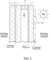
- the IG window unit includes at least first (1), second (30) and third (31) glass substrates spaced apart from one another, wherein the first substrate 1 as shown in Figs. 2-3 supports an ultraviolet (UV) reflecting coating 150 for reflecting UV radiation so that birds are capable of more easily seeing the window.
- At least two of the substrates are laminated to one another via a polymer-based laminating film (e.g., of or including PVB, EVA, or SGP) 200.
- a polymer-based laminating film e.g., of or including PVB, EVA, or SGP
- the polymer-based laminating film 200 is preferably of a type that has a high absorption of UV, for example a film 200 that has a UV absorption from 350-380 nm of at least 80%, more preferably of at least 90%, and most preferably at least 95%. Note that this is not a typical feature of laminating films such as PVB, because certain PVB films for example do not have a high UV absorption (while others do).
- substrates 30 and 31 are laminated to each other in the Fig. 2 embodiment, and substrates 1 and 30 are laminated to each other in the Fig. 3 embodiment via laminating film 200.
- the UV reflecting coating 150 is patterned so that it is not provided across the entirety of the IG window unit.
- Example embodiments of this invention provide a new IGU configuration with laminated glass to further increase the contrast ratio between areas with UV reflecting coating and areas without the UV reflecting coating.
- PVB used in laminated glass can absorb much of UV wavelengths between 300nm and 400nm, thereby increasing contrast ratio between areas with UV reflecting coating 150 and areas without the UV reflecting coating 150.
- the provision of the laminated substrates, via laminating film 200, in the IG window unit is particularly advantageous for bird collision windows, because it: (a) increases the contrast ratio of the IG window unit between areas having the UV reflecting coating and areas not having the UV reflecting coating, thereby making the window more visible to birds and reducing the likelihood of bird collisions, (b) increases mechanical durability of the IG window unit and reduces the likelihood of glass cracking due to bird collisions, and (c) in certain embodiments allows two single-coated-side glass substrates to be provided which improves production durability and processing so as to reduce likelihood of coating damage during processing, manufacturing, and/or shipping.
- a pair of spaced apart substrates may be separated from one another by at least one seal and/or spacer 15 in certain example embodiment.
- a low-E coating 19 for blocking at least some infrared (IR) radiation and a UV reflecting blocking coating 150 for reflecting UV radiation to make the window more visible to birds in order to reduce collisions.
- the low-E coating 19 may have an emissivity (E n ) of no greater than 0.10 and/or a sheet resistance (R s ) of no greater than 8 ohms/square.
- the UV reflecting coating 19 may block at least 38% (more preferably at least 40%, more preferably at least 55%, even more preferably at least 60%, and possibly at least 65%) of UV radiation in at least a substantial part of the range from 350 to 440 nm (or alternatively in a substantial part of the range from 300-400 nm).
- This is significant UV blockage/reflection, and represents a significant advantage over coatings described in U.S. Patent No. 8,114,488 for example and without limitation. This increases the UV reflection of the window unit intended for commercial or residential applications in order to make such windows more visible to birds thereby preventing or reducing bird collisions.
- the UV reflecting/blocking coating 150 is patterned (e.g., in a grid pattern or in a parallel striped pattern) on the window unit which can make it even more visible to birds to further reduce bird collisions.
- the IG window unit preferably has a visible transmission of at least about 50%, more preferably of at least about 60%, and even more preferably of at least about 65% or at least about 70%.
- the film side UV reflectance may have: (a) a visible transmission of at least about 70%, more preferably of at least about 80%, and even more preferably of at least about 85%, (b) the film side UV reflectance of at least 38% (more preferably at least 40%, more preferably at least 55%, even more preferably at least 60%, and possibly at least 65%), and (c) a film side visible reflectance of less than about 20%, more preferably less than about 15%, and most preferably less than about 10%.
- the film side UV reflectance may be at least about 4 times higher than the film side visible reflectance of the monolithic coated article (more preferably at least about 5 times higher, even more preferably at least about 8 times higher, and possibly at least 10 times higher).
- Figs. 2-3 are cross sectional views of a portion of an IG window unit.
- the IG window unit includes glass substrate 1, glass substrate 30, and glass substrate 31.
- glass substrate 1 and glass substrate 30 are spaced apart from one another at least by one or more peripheral seal(s) or spacer(s) 15, so as to define an air gap 17 therebetween.
- the UV reflecting coating 150 is provided on the outboard side of glass substrate 1, and the low-E coating 19 is provided on the inboard side of substrate 1.
- the air gap may or may not be filled with a gas such as argon gas.
- an array of spacers (not shown) may be provided between the substrates 1 and 30 in Fig.
- the spacer(s) 15, other spacer(s), and/or peripheral seal space the two substrates 1 and 30 in Fig. 2 apart from one another so that the substrates do not contact one another and so that a space or gap 17 is defined therebetween.
- the space 17 between the substrates 1, 30 may be evacuated to a pressure lower than atmospheric in certain example embodiments, and/or may be filled with a gas (e.g., Ar) in certain example embodiments. In certain example embodiments, it is possible to suspend foil or other radiation reflective sheet(s) (not shown) in space 17.
- Glass substrates 30 and 31 are laminated to each other via laminating film 200, on the inboard side (side to be closest to the building interior) of the air gap 17 in the Fig. 2 embodiment.
- the polymer based laminating film 17 preferably absorbs UV, and may be of or include PVB (polyvinyl butyral), EVA, SGP (Sentry Glass Plus), or the like in different example embodiments of this invention.
- PVB polyvinyl butyral
- EVA polyvinyl butyral
- SGP Surface Glass Plus
- each glass substrate may be of the soda-lime-silica type of glass, or any other suitable type of glass, and may be for example from about 1 to 10 mm thick in certain example embodiments of this invention.
- glass substrate 30 and glass substrate 31 are spaced apart from one another at least by one or more peripheral seal(s) or spacer(s) 15, so as to define an air gap 17 therebetween.
- the UV reflecting coating 150 is provided on the outboard side of glass substrate 1 closest to the building exterior, and the low-E coating 19 is provided on the inboard side of substrate 30.
- the air gap 17 may or may not be filled with a gas such as argon gas.
- an array of spacers may be provided between the substrates 30 and 31 in Fig. 3 in a viewing area of the window for spacing the substrates from one another as in the context of a vacuum IG window unit.
- the spacer(s) 15, other spacer(s), and/or peripheral seal space the two substrates 30 and 31 in Fig. 3 apart from one another so that the substrates do not contact one another and so that a space or gap 17 is defined therebetween.
- the space 17 between the substrates 31, 30 may be evacuated to a pressure lower than atmospheric in certain example embodiments, and/or may be filled with a gas (e.g., Ar) in certain example embodiments.
- a gas e.g., Ar
- glass substrates 1 and 30 are laminated to each other via polymer based laminating film 200, on the outboard side (side to be closest to the building exterior) of the air gap 17.
- the polymer based laminating film 17 preferably absorbs UV, and may be of or include PVB, EVA, SGP, or the like.
- Figs. 2 and 3 differ from each other mainly in that (i) the laminated structure is provided on the inboard side of the air gap17 and on the inboard side of the low-E coating 19 in Fig. 2 , but is provided on the outboard side of the air gap 17 and low-E coating 19 in Fig. 3 , and (ii) Fig. 3 provides for a structure allowing two single-coated-side glass substrates 1 and 30 to be provided which improves production durability and processing so as to reduce likelihood of coating damage during processing, manufacturing, and/or shipping. With respect to point (ii), in Fig.
- glass substrate 1 is only coated on one side with UV coating 150, and glass substrate 30 is only coated on one side with low-E coating 19, in the manufacturing process (laminating film 200 is an interlayer for laminating/adhering purposes and is not a film that is sputter-deposited or otherwise deposited onto a surface of a substrate).
- laminated film 200 is an interlayer for laminating/adhering purposes and is not a film that is sputter-deposited or otherwise deposited onto a surface of a substrate.
- the Fig. 2 embodiment requires that both sides of glass substrate 1 be coated, one side with the UV coating 150 and the other side with the low-E coating, which can increase risk of damage during processing, shipping, and/or handling.
- the IG window units of Figs. 2-3 include low-E coating 19 that is supported on an inboard side of glass substrate 1 ( Fig. 2 ) or on an inboard side of glass substrate 30 ( Fig. 3 ).
- Low-E coating 19 includes one or more layers, although in many embodiments it is a multi-layer coating.
- Low-E coating 19 includes at least one IR reflecting layer (e.g., based on silver or gold) sandwiched between at least first and second dielectric layers. Since one example function of low-E coating 19 is to block (i.e., reflect and/or absorb) certain amounts of IR radiation and prevent the same from reaching the building interior, the solar management coating 9 includes at least one IR blocking (i.e., IR reflecting and/or absorbing) layer.
- Example IR blocking layer(s) which may be present in coating 19 are of or include silver (Ag), nickel-chrome (NiCr), gold (Au), and/or any other suitable material that blocks significant amounts of IR radiation. It will be appreciated by those skilled in the art that IR blocking layer(s) of low-E coating 19 need not block all IR radiation, but only need to block significant amounts thereof. In certain embodiments, each IR blocking layer of coating 19 is provided between at least a pair of dielectric layers.
- Example dielectric layers include silicon nitride, titanium oxide, silicon oxynitride, tin oxide, and/or other types of metal-oxides and/or metal-nitrides.
- each IR blocking layer may also be provided between a pair of contact layers of or including a material such as an oxide and/or nitride of nickel-chrome or any other suitable material.
- Example low-E coatings 19 are described in U.S. Patent Nos.
- the low-E coating 19 before and/or after optional heat treatment (e.g., thermal tempering and/or heat bending), may have a sheet resistance (R s ) of no greater than 8 ohms/square, more preferably no greater than 6 ohms/square, and most preferably no greater than 4 ohms/square.
- the low-E coating 19 may have an emissivity (E n ) after heat treatment of no greater than 0.10, more preferably no greater than 0.07, and even more preferably no greater than 0.05 (before and/or after optional heat treatment).
- solar management coatings 19 herein are not limited to these particular coatings, and any other suitable solar management coatings capable of blocking amounts of IR radiation may instead be used.
- Solar management coatings 19 herein may be deposited on substrate(s) 1 and/or 30 in any suitable manner, including but not limited to sputtering, vapor deposition, and/or any other suitable technique.
- the IG window units further include UV reflecting coating 150 for reflecting significant amounts of UV radiation thereby making the window more visible to birds.
- Coatings 150 may be sputter-deposited in example embodiments of this invention.
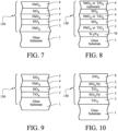
- UV reflecting coating 150 may be, for purposes of example and without limitation, any of the UV reflecting coatings illustrated in Figs. 7-11 . This increases the UV reflection of the window unit in order to make such windows more visible to birds thereby preventing or reducing bird collisions.
- the use of such coatings 150 herein enhances the performance of the glass or window by increasing the UV reflectance beyond the normal limits of raw uncoated plate glass in the 300-440 nm range of the spectrum.
- the UV reflecting coating 150 is in direct contact with the glass substrate 1 on the exterior surface thereof, and is not part of a low-E coating 19.
- IR reflecting layers e.g., silver based, gold based, NiCr, or IR reflecting TCO-based layers
- the low-E coating is provided on the other side of substrate 1 from coating 150 (not part of this invention) or alternatively on substrate 30 (according to this invention).
- the UV reflecting coating 150 may block at least 38% (more preferably at least 40%, more preferably at least 55%, even more preferably at least 60%, and possibly at least 65%) of UV radiation in at least a substantial part of the range from 350 to 440 nm (or alternatively in a substantial part of the range from 300-400 nm).
- the UV reflecting coating 150 is patterned (e.g., in the shape of a grid or in substantially parallel or non-parallel stripes) on the surface of substrate 1 as shown in Figs. 2-3 .
- the patterned shape of coating 150 may be formed as follows, for purposes of example.
- a pattern (not shown) is provided on the surface of substrate 1 prior to the coating 150 being formed, with the pattern being located in areas which are ultimately to be free of coating 150.
- a coating 150 is continuously formed across the entire or substantially the entire surface of substrate 1 over the pattern.
- the pattern can then be removed (along with the portions of coating 150 located directly over it) in order to create a patterned coating 150, so that the coating 150 remains on only the portions of the substrate where the original pattern was not deposited.
- a patterned coating 150 can be formed in such a manner in example embodiments of this invention.
- the remaining patterned coating 150 is substantially invisible to human eyes, but is visible to bird eyes as explained above
- the window unit e.g., insulating glass (IG) window unit and/or laminated window unit
- the IG window unit includes three substrates (e.g., glass substrates) spaced apart from one another, and at least one of the substrates supports an ultraviolet (UV) reflecting coating for reflecting UV radiation.
- the UV reflecting coating is a coating designed without any IR reflecting layer(s) of silver or gold.
- the UV reflecting coating 150 may be patterned by a laser (e.g., femto laser) which is used to either entirely or partially remove (e.g., via laser ablation) a portion of the coating in a pattern, so that after patterning by the laser the patterned coating is either not provided across the entirety of the window unit and/or is non-uniform in UV reflection across the window unit so that the UV reflection differs across different areas of the window thereby making the window unit more visible to birds which can see UV radiation and detect that pattern.
- the as-deposited UV reflecting coating entirely remains on the substrate in areas not patterned by the laser, and partially remains in areas patterned by the laser.
- Femto lasers have been found to be advantageous in that they can efficiently pattern such UV reflecting coatings 150 without damaging the underlying glass substrate, and can more easily be used to remove only part of such a coating in patterned areas so as to maintain substantially the same surface energy in both patterned and non-patterned areas of the UV reflective coating.
- the user of the Femto lasers result in a final product with less haze that if a non-Femto laser has been used.
- the final coated article, including both patterned and nonpatterned areas has a haze value of no greater than 0.4, more preferably no greater than 0.3, and most preferably no greater than 0.2.
- a laser fluence of from 0.01 to 2 J/cm 2 , and most preferably 0.05 to 1 J/cm 2 advantageous results in a smoother ablation of the patterned areas and allows the ablation to occur with partial coating removal but without any significant damage to the glass substrate and without significant haze in the patterned areas.
- the patterned UV reflecting coating 150 is preferably substantially neutral in the visible range, so that the patterning of the UV coating is not reasonably seen by humans via the naked eye. Another advantage of laser is that we can do random patterning on the fly.
- a method of making a window for reducing bird collisions comprising a first glass substrate and a ultraviolet (UV) reflective coating supported by at least the first glass substrate, the method comprising: having the first glass substrate and the ultraviolet (UV) reflective coating supported by at least the first glass substrate; emitting a laser beam from at least one laser source, the laser beam comprising optical pulses with (i) a duration below 1000 Femtoseconds and/or (ii) a fluence from 0.01 to 2.0 J/cm 2 ; wherein the laser beam comprising optical pulses is incident upon the UV reflective coating and patterns the UV reflective coating into patterned and non-patterned areas which have different respective UV reflectances, the laser beam having been incident upon the patterned areas but not the non-patterned areas.
- the laser beam may comprise optical pulses with a duration below 100 Femtoseconds, and possibly a duration below 50 Femtoseconds. All layers of the UV reflective coating may be dielectric layers, or alternatively the UV reflective coating may be a low-E coating having at least one IR reflective layer sandwiched between at least first and second dielectric layers.
- Figs. 4-6 demonstrate surprising technical advantages associated with the IG window units of Figs. 2-3 compared to that of Fig. 1 , and also demonstrate surprising technical advantages of the Fig. 3 embodiment (outboard laminated structure), according to this invention, compared to the Fig. 2 embodiment (inboard laminated structure), not part of this invention.
- Fig. 4 is a wavelength (nm) versus Transmission (T) % and Reflection (R) %, showing transmission and reflection as a function of wavelength (nm) for an example IG window unit of the Fig.
- Fig. 5 is a wavelength (nm) versus Transmission (T) % and Reflection (R) %, showing transmission and reflection as a function of wavelength (nm) for an example IG window unit of the Fig.
- Fig. 6 is a wavelength (nm) versus Transmission (T) % and Reflection (R) %, showing transmission and reflection as a function of wavelength (nm) for an example IG window unit of prior art Fig.
- Fig. 4 corresponds to an example of the Fig. 3 embodiment
- Fig. 5 corresponds to an example of the Fig. 2 embodiment
- Fig. 6 corresponds to prior art Fig. 1 .
- lamination when laminating film 200 is present laminating together a pair of substrates reduces UV transmission for both areas with and without UV reflecting coating, thereby enhancing the transmissive contrast ratio CR(TR), which is defined as the ratio of transmittance without UV coating to that with UV coating.
- the contrast ratio has been found to be higher for the laminated IGUs of Figs. 2-3 around 365-369 nm (compared to Fig. 1 ).
- the transmission curves for inboard laminated structure and outboard laminated structures are nearly identical, so the improvement is essentially the same in the transmission mode for the Fig. 2 and 3 embodiments.
- Fig. 3 IG unit with the outboard laminated structure has been found to realize improved performance features compared to both the Fig. 1 and Fig. 2 IG units.
- Fig. 3 has a laminated structure (compared to Fig. 1 ) and because Fig. 3 has the laminated structure on the outboard side of the air gap and low-E coating (compared to Fig. 2 ).
- Figs. 4-6 illustrate that the IG units of Figs. 1-3 have very different reflection curves in UV spectra.
- UV light from the sun is mostly absorbed by PVB 200 before it reaches the low-E coating 19.
- a certain portion of UV light reaches and is reflected by the low-E coating 19; this amount of extra UV reflection reduces the reflective contrast ratio CR(RF) which is defined as the ratio of reflectance in areas with UV coating 150 to areas without UV coating 150.
- the reflective contrast ratio of the IG unit has surprisingly been found to be significantly higher for the Fig. 3 embodiment of this invention, compared to the Fig. 2 embodiment, and thus the Fig. 3 IG window unit will be more visible to birds and thus realize less bird collisions than both Fig. 1 and the Fig. 2 embodiment.
- Figs. 7-11 are cross sectional views of various UV reflecting coatings 150 that may be used on substrate 1 in the IG window unit of Fig. 1 or Fig. 2 in example embodiments of this invention.
- Glass substrate 1 may be soda-lime-silica based glass or any other suitable type of glass, and may be from about 1-10 mm thick, more preferably from about 2-6 mm thick, in example embodiments of this invention.
- UV reflecting coating 150 includes high index transparent dielectric layers 2, 4 and 6 of or including niobium oxide (e.g., Nb 2 O 5 , NbO 2 and/or NbO) and low index transparent dielectric layers 3 and 5 of or including silicon oxide (e.g., SiO 2 which may or may not be doped with aluminum and/or nitrogen).
- layer 6 in Fig. 7 is optional and can be removed to improve UV reflectance in certain instances, or can instead be of or including zirconium oxide.
- one or both of the silicon oxide layers 3 and/or 5 may be doped with other material such as from about 1-8% aluminum and/or from about 1-10% nitrogen.
- layers 2, 4 and 6 may also be doped with other material in certain example instances.
- layer 6 is the outermost layer of the coating 150 and may be exposed to air.
- Each of layers 2-6 is considered "transparent" to visible light because each of these layers, standing alone, is substantially transparent to visible light (e.g., at least about 50% transparent, more preferably at least about 60% or 70% transparent to visible light).
- High index transparent dielectric layers 2, 4 and 6 of or including niobium oxide may have a refractive index (n) of from about 2.15 to 2.5, more preferably from about 2.2 to 2.4, and most preferably from about 2.25 to 2.35 (at 550 nm).
- the niobium oxide may be replaced with titanium oxide (e.g., TiO 2 ), zirconium oxide, hafnium oxide (e.g., HfO 2 ), cerium oxide (e.g., CeO 2 ), zinc sulfide, or bismuth oxide (e.g., Bi 2 O 3 ) in one or more of high index layers 2, 4 and/or 6.
- titanium oxide e.g., TiO 2
- zirconium oxide hafnium oxide (e.g., HfO 2 ), cerium oxide (e.g., CeO 2 ), zinc sulfide, or bismuth oxide (e.g., Bi 2 O 3 )
- layers 2 and 4 are of or including niobium oxide
- layers 3 and 5 are of or including silicon oxide.
- Low index transparent dielectric layers 3 and 5 of or including silicon oxide may have a refractive index (n) of from about 1.4 to 1.7, more preferably from about 1.4 to 1.6, and most preferably from about 1.45 to 1.55 (all refractive index n values herein are measured at 550 nm).
- Transparent dielectric layers 2-6 are preferably deposited by sputtering in example embodiments of this invention.
- transparent dielectric layers 2, 4 and 6 of or including niobium oxide may be sputter deposited via at least one sputtering target of or including Nb, via sputtering in an atmosphere including a mixture of argon and reactive oxygen gases.
- transparent dielectric layers 3 and 5 of or including silicon oxide may be sputter deposited via at least one sputtering target of or including Si or SiAl, via sputtering in an atmosphere including a mixture of argon and reactive oxygen gases.
- Rotation C-Mag sputtering targets, or other types of targets may be used. In sputtering operations, sufficient reactive oxygen gas may be used to achieve the refractive index values discussed herein.
- Ceramic targets may alternatively be used to sputter deposit one or more of these layers. While layers 2-6 are preferably deposited via sputtering, it is possible that they may be deposited via other techniques in alternative embodiments of this invention. While coating 150 consists of five layers in the Fig.
- a protective layer of or including zirconium oxide may be provided in the coating 150 as the uppermost layer over and directly contacting layer 6.
- Coating 150 in the Fig. 7 embodiment and in other example embodiments contains no metallic reflective layer.
- Fig. 8 is a cross sectional view of another UV reflecting coating 150 that may be used on substrate 1 in the Fig. 2 or Fig. 3 IG window unit.
- the Fig. 8 embodiment is the same as the Fig. 7 embodiment, except that transparent dielectric barrier layer 70 is provided between the glass substrate 1 and high index layer 2.
- layer 6 in Fig. 8 is optional and can be removed to improve UV reflectance in certain instances, or can instead be of or including zirconium oxide.
- the barrier layer 70 is of or including silicon nitride (e.g., Si 3 N 4 ) in certain example embodiments of this invention. Barrier layer 70 may optionally be used in the coatings of any of Figs. 7-11 , but is only shown in Fig. 8 for purposes of simplicity.
- silicon nitride based barrier layer 70 may be doped with other material such as from about 1-8% aluminum and/or from about 1-10% oxygen.
- the Fig. 8 embodiment is particular useful in heat treated (e.g., thermally tempered) embodiments, where the barrier layer 70 helps prevent or reduce migration of elements (e.g., Na) from the glass substrate into the coating during the high temperature heat treatment.
- heat treatment e.g., thermal tempering
- Such heat treatment may include, for example heating the coated article in an oven or the like at temperature(s) of at least about 580 degrees C, more preferably of at least about 600 degrees C.
- the coating of the Fig. 8 embodiment may or may not be heat treated (e.g., thermally tempered) in example embodiments of this invention.
- Fig. 9 is a cross sectional view of another UV reflecting coating 150 that may be used on substrate 1 in the Fig. 2 or Fig. 3 IG window unit.
- the Fig. 9 embodiment is the same as the Fig. 7 embodiment, except that layer 6 is removed.
- the coated article shown in Fig. 9 may have, for example, a film side UV reflectance of from about 40-45%, with an example being about 41% (reflecting at least this much UV radiation in at least a substantial part of the range from 300-400 nm).
- a film side UV reflectance of from about 40-45%, with an example being about 41% (reflecting at least this much UV radiation in at least a substantial part of the range from 300-400 nm).
- layer 5 is the outermost layer of UV reflecting coating 150, and layer 2 is of or including titanium oxide (e.g., TiO 2 ), layer 3 is of or including silicon oxide (e.g., SiO 2 which may or may not be doped with aluminum and/or nitrogen), layer 4 is of or including niobium oxide (e.g., Nb 2 O 5 , NbO 2 and/or NbO), and layer 5 is of or including silicon oxide (e.g., SiO 2 which may or may not be doped with aluminum and/or nitrogen).
- the coating of the Fig. 9 embodiment may also include an overcoat of or including zirconium oxide (e.g., ZrO 2 ).
- zirconium oxide e.g., ZrO 2
- transparent dielectric layer 2 of or including titanium oxide may be from about 5-40 nm thick, more preferably from about 10-25 nm thick, even more preferably from about 10-20 nm thick, with an example thickness being from about 13-16 nm;
- transparent dielectric layer 3 of or including silicon oxide may be from about 30-100 nm thick, more preferably from about 40-80 nm thick, even more preferably from about 50-70 nm thick, with an example thickness being about 60 nm;
- transparent dielectric layer 4 of or including niobium oxide may be from about 15-150 nm thick, more preferably from about 20-125 nm thick, even more preferably from about 95-120 nm thick, with an example thickness being about 33 nm or about 105 nm;
- transparent dielectric layer 5 of or including silicon oxide may be from about 40-130 nm thick, more preferably from about 50-110 nm thick, even more preferably from about 60-100
- niobium oxide based layer 4 is preferably substantially thicker than titanium oxide based layer 2.
- niobium oxide based layer 4 is at least about 40 nm thicker (more preferably at least about 50 nm thicker, and most preferably at least about 70 nm thicker) than titanium oxide based layer 2.
- niobium oxide based layer 4 is also preferably thicker than each of layers 3 and 5, for example layer 4 being at least about 10 nm thicker and most preferably at least about 15 nm thicker than each of silicon oxide based layers 3 and 5.
- Silicon oxide based layer 5 is at least about 10 or 20 nm thicker than is silicon oxide based layer 3 in certain embodiments of the Fig. 2 , 3 , 9 embodiment of this invention.
- a protective layer (not shown) of or including zirconium oxide may be provided as the outermost layer over layer 5 in the Fig. 9 coating (similar to the protective outer layer in Fig. 10 ).
- Fig. 10 is a cross sectional view of another UV reflecting coating 150 that may be used on substrate 1 in the Fig. 2 or Fig. 3 IG window unit.
- the coated article shown in Fig. 10 may have, for example, a film side UV reflectance of from about 60-70%, with an example being about 65% (reflecting at least this much UV radiation in at least a substantial part of the range from 300-400 nm).
- a film side UV reflectance of from about 60-70%, with an example being about 65% (reflecting at least this much UV radiation in at least a substantial part of the range from 300-400 nm).
- layer 2 is of or including titanium oxide (e.g., TiO 2 )
- layers 3 and 5 are of or including silicon oxynitride (e.g., which may or may not be doped with aluminum)
- layer 4 is of or including titanium oxide (e.g., TiOz)
- outermost protective layer 8 is of or including zirconium oxide (e.g., ZrO 2 ).
- zirconium oxide e.g., ZrO 2
- transparent dielectric layer 2 of or including titanium oxide may be from about 5-40 nm thick, more preferably from about 10-25 nm thick, even more preferably from about 10-20 nm thick, with an example thickness being about 17 nm;
- transparent dielectric layer 3 of or including silicon oxynitride may be from about 30-100 nm thick, more preferably from about 40-80 nm thick, even more preferably from about 45-70 nm thick, with an example thickness being about 50 nm;
- transparent dielectric layer 4 of or including titanium oxide may be from about 10-80 nm thick, more preferably from about 15-50 nm thick, even more preferably from about 20-40 nm thick, with an example thickness being about 30 nm;
- transparent dielectric layer 5 of or including silicon oxynitride may be from about 50-130 nm thick, more preferably from about 70-120 nm thick, even more preferably from about 80-110 nm thick, with
- titanium oxide based layer 4 is at least about 8 nm thicker (more preferably at least about 10 nm thicker, and most preferably at least about 15 nm thicker) than titanium oxide based layer 2.
- silicon oxynitride based layer 5 is at least about 10, 20 or 30 nm thicker than is silicon oxynitride based layer 3 in certain embodiments of the Fig. 2 , 3 , 10 embodiment of this invention.
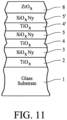
- Fig. 11 is a cross sectional view of another UV reflecting coating 150 that may be used on the outboard side of substrate 1 in the Fig. 2 or Fig. 3 IG window unit.
- the coated article shown in Fig. 11 may have, for example, a film side UV reflectance of from about 50-80%, with an example being about 70% (reflecting at least this much UV radiation in at least a substantial part of the range from 300-400 nm).
- a film side UV reflectance of from about 50-80%, with an example being about 70% (reflecting at least this much UV radiation in at least a substantial part of the range from 300-400 nm).
- layers 2, 4 and 4' are of or including titanium oxide (e.g., TiO 2 ), and layers 3, 5 and 5' are of or including silicon oxynitride (e.g., which may or may not be doped with aluminum), and outermost protective layer 8 is of or including zirconium oxide (e.g., ZrO 2 ).
- titanium oxide e.g., TiO 2
- layers 3, 5 and 5' are of or including silicon oxynitride (e.g., which may or may not be doped with aluminum)
- outermost protective layer 8 is of or including zirconium oxide (e.g., ZrO 2 ).
- transparent dielectric layer 2 of or including titanium oxide may be from about 5-40 nm thick, more preferably from about 10-25 nm thick, even more preferably from about 10-20 nm thick, with an example thickness being about 11 nm;
- transparent dielectric layer 3 of or including silicon oxynitride may be from about 30-100 nm thick, more preferably from about 40-80 nm thick, even more preferably from about 45-70 nm thick, with an example thickness being about 63 nm;
- transparent dielectric layer 4 of or including titanium oxide may be from about 10-80 nm thick, more preferably from about 15-50 nm thick, even more preferably from about 20-40 nm thick, with an example thickness being about 37 nm;
- transparent dielectric layer 5 of or including silicon oxynitride may be from about 10-70 nm thick, more preferably from about 15-60 nm thick, even more preferably from about 20-40 nm thick, with an example
- high index layers 4 and 4' are preferably substantially thicker than high index layer 2.
- titanium oxide based layers 4 and 4' may be at least about 8 nm thicker (more preferably at least about 10 nm thicker, and most preferably at least about 15 nm thicker) than high index titanium oxide based layer 2.
- silicon oxynitride based layer 5' is at least about 10, 20 or 30 nm thicker than are silicon oxynitride based layers 3 and/or 5 in certain embodiments of the Fig. 2 , 3 , 11 embodiment of this invention.
- Fig. 2 , 3 , 11 embodiment of this invention are silicon oxynitride based layers 3 and/or 5 in certain embodiments of the Fig. 2 , 3 , 11 embodiment of this invention.
- the silicon oxynitride based layers 3, 5 and 5' may have a refractive index n (measured at 550 nm) of from about 1.6 to 1.8, more preferably from about 1.65 to 1.75, and most preferably 1.7.
- n measured at 550 nm
- the Fig. 10-11 embodiments are also surprisingly advantageous in that their optical properties have been found to be close to that of uncoated float glass, which makes the coatings 150 essentially invisible to human eyes.
Landscapes
- Life Sciences & Earth Sciences (AREA)
- Chemical & Material Sciences (AREA)
- Engineering & Computer Science (AREA)
- Chemical Kinetics & Catalysis (AREA)
- General Chemical & Material Sciences (AREA)
- Geochemistry & Mineralogy (AREA)
- Materials Engineering (AREA)
- Organic Chemistry (AREA)
- Birds (AREA)
- Insects & Arthropods (AREA)
- Pest Control & Pesticides (AREA)
- Wood Science & Technology (AREA)
- Zoology (AREA)
- Environmental Sciences (AREA)
- Civil Engineering (AREA)
- Structural Engineering (AREA)
- Joining Of Glass To Other Materials (AREA)
- Securing Of Glass Panes Or The Like (AREA)
- Surface Treatment Of Glass (AREA)
- Laminated Bodies (AREA)
- Catching Or Destruction (AREA)
Claims (15)
- Isolierglasfenstereinheit, umfassend:ein erstes Glassubstrat (1);ein zweites Glassubstrat (30);ein drittes Glassubstrat (31);wobei das erste Glassubstrat (1) an einer Außenseite der Isolierglasfenstereinheit so vorgesehen ist, dass es einer Außenseite eines Gebäudes, in dem die Isolierglasfenstereinheit montiert werden soll, zugewandt ist;wobei das zweite Glassubstrat (30) zwischen mindestens dem ersten (1) und dem dritten (31) Glassubstrat vorgesehen ist;wobei das dritte Glassubstrat (31) an einer Innenseite der Isolierglasfenstereinheit so vorgesehen ist, dass es einer Innenseite eines Gebäudes, in dem die Isolierglasfenstereinheit montiert werden soll, zugewandt ist;eine strukturierte UV-reflektierende Beschichtung (150), die auf dem ersten Glassubstrat (1) und auf einer Außenfläche der Isolierglasfenstereinheit so vorgesehen ist, dass sie einer Außenseite eines Gebäudes, in dem die Isolierglasfenstereinheit montiert werden soll, zugewandt ist;wobei das erste (1) und das zweite (30) Glassubstrat über einen polymerhaltigen Laminierfilm (200) miteinander laminiert sind;eine Low-E-Beschichtung (19), die auf einer Seite des zweiten Glassubstrats (30), die dem polymerhaltigen Laminierfilm (200) gegenüberliegt, so vorgesehen ist, dass sich das zweite Glassubstrat (30) zwischen der Low-E-Beschichtung (19) und dem polymerhaltigen Laminierfilm (200) befindet;wobei sich das erste Glassubstrat (1) zwischen der strukturierten UVreflektierenden Beschichtung (150) und dem polymerhaltigen Laminierfilm (200) befindet;wobei die UV-reflektierende Beschichtung (150) nicht Teil einer Low-E-Beschichtung (19) ist und keine IR-reflektierende Schicht aus Silber oder Gold enthält; undwobei das zweite Glassubstrat (30) über mindestens einen Luftspalt vom dritten Glassubstrat (31) so beabstandet ist, dass sich eine laminierte Struktur, die das erste Glassubstrat (1), das zweite Glassubstrat (30) und den polymerhaltigen Laminierfilm (200) beinhaltet, auf einer Außenseite des Luftspalts und auf einer Außenseite der Low-E-Beschichtung (19) befindet.
- Isolierglasfenstereinheit nach Anspruch 1, wobei die UV-reflektierende Beschichtung (150) erste, zweite, dritte und vierte Schicht in dieser Reihenfolge vom ersten Glassubstrat (1) ausgehend umfasst, und wobei die erste und die dritte Schicht Schichten mit hohem Index sind, die einen Brechungsindex von mindestens etwa 2,25 aufweisen, und die zweite und die vierte Schicht Schichten mit niedrigem Index sind, die einen Brechungsindex von nicht größer als 1,8 aufweisen, wobei die Brechungsindizes bei 550 nm gemessen werden;wobei die erste, zweite, dritte und vierte Schicht jeweils dielektrische Schichten sind, die mindestens 50 % für sichtbares Licht durchlässig sind; undwobei die Isolierglasfenstereinheit eine sichtbare Transmission von mindestens etwa 50 % aufweist, und die UV-reflektierende Beschichtung (150) mindestens 40 % der UV-Strahlung im Bereich von 300-400 nm reflektiert.
- Isolierglasfenstereinheit nach einem vorstehenden Anspruch, wobei die UV-reflektierende Beschichtung (150) mindestens 50 % der UV-Strahlung im Bereich von 300-400 nm reflektiert.
- Isolierglasfenstereinheit nach einem vorstehenden Anspruch, wobei die UV-reflektierende Beschichtung (150) mindestens 60 % der UV-Strahlung im Bereich von 300-400 nm reflektiert.
- Isolierglasfenstereinheit nach einem vorstehenden Anspruch, wobei die Low-E-Beschichtung (19) mindestens eine Infrarot- (IR-) reflektierende Schicht umfasst, die Silber umfasst, die sich zwischen mindestens der ersten und der zweiten dielektrischen Schicht befindet.
- Isolierglasfenstereinheit nach einem vorstehenden Anspruch, wobei die Low-E-Beschichtung (19) erste und zweite Infrarot-, IR-, reflektierende Schicht, die Silber umfasst, mindestens eine dielektrische Schicht, die zwischen der ersten IRreflektierenden Schicht und dem zweiten Glassubstrat (30) vorgesehen ist, mindestens eine weitere dielektrische Schicht, die zwischen der ersten und der zweiten IRreflektierenden Schicht vorgesehen ist, umfasst, und wobei die Low-E-Beschichtung (19) ein normales Emissionsvermögen (En) von nicht größer als 0,10 und/oder einen Schichtwiderstand (Rs) von nicht größer als 8 Ohm/Quadrat aufweist.
- Isolierglasfenstereinheit nach einem vorstehenden Anspruch, wobei das zweite (30) und das dritte (31) Glassubstrat durch mindestens einen Abstandshalter und/oder eine Randdichtung so voneinander beabstandet sind, dass sie den Luftspalt zwischen dem zweiten (30) und dem dritten (31) Glassubstrat definieren.
- Isolierglasfenstereinheit nach einem vorstehenden Anspruch, wobei der Luftspalt mit Gas gefüllt ist, das bevorzugt Argongas umfasst.
- Isolierglasfenstereinheit nach einem vorstehenden Anspruch, wobei der Luftspalt auf einen Druck unterhalb Atmosphärendruck evakuiert wird.
- Isolierglasfenstereinheit nach einem vorstehenden Anspruch, wobei die UV-reflektierende Beschichtung (150) das erste Glassubstrat (1) direkt berührt.
- Isolierglasfenstereinheit nach einem vorstehenden Anspruch, wobei die Low-E-Beschichtung (19) das zweite Glassubstrat (30) direkt berührt.
- Isolierglasfenstereinheit nach einem vorstehenden Anspruch, wobei der polymerhaltige Laminierfilm (200) PVB umfasst.
- Isolierglasfenstereinheit nach einem vorstehenden Anspruch, wobei das zweite (30) und das dritte (31) Glassubstrat weiter voneinander beabstandet sind als das erste (1) und das zweite (30) Glassubstrat voneinander getrennt sind, bevorzugt wobei das zweite (30) und das dritte (31) Glassubstrat mindestens 5 mm weiter voneinander beabstandet sind als das erste (1) und das zweite (30) Glassubstrat voneinander getrennt sind.
- Isolierglasfenstereinheit nach einem vorstehenden Anspruch, wobei die Isolierglasfenstereinheit eine Transmission von nicht größer als 5 % bei 370 nm in allen Bereichen, die die UV-reflektierende Beschichtung (150) beinhalten, und in Bereichen, die die UV-reflektierende Beschichtung (150) nicht beinhalten, aufweist.
- Isolierglasfenstereinheit nach einem vorstehenden Anspruch, wobei der Laminierfilm (200) eine UV-Absorption von 350-380 nm von mindestens 90 % aufweist.
Priority Applications (1)
| Application Number | Priority Date | Filing Date | Title |
|---|---|---|---|
| EP24195917.0A EP4464157A3 (de) | 2017-09-18 | 2018-09-18 | Ig-fenstereinheit mit laminierten substraten zur verhinderung von vogelkollisionen |
Applications Claiming Priority (2)
| Application Number | Priority Date | Filing Date | Title |
|---|---|---|---|
| US201762559684P | 2017-09-18 | 2017-09-18 | |
| PCT/US2018/051404 WO2019055953A1 (en) | 2017-09-18 | 2018-09-18 | WINDOW INSULATING WINDOW UNIT COMPRISING LAMINATED SUBSTRATES FOR AVOIDING COLLISION WITH BIRDS |
Related Child Applications (2)
| Application Number | Title | Priority Date | Filing Date |
|---|---|---|---|
| EP24195917.0A Division EP4464157A3 (de) | 2017-09-18 | 2018-09-18 | Ig-fenstereinheit mit laminierten substraten zur verhinderung von vogelkollisionen |
| EP24195917.0A Division-Into EP4464157A3 (de) | 2017-09-18 | 2018-09-18 | Ig-fenstereinheit mit laminierten substraten zur verhinderung von vogelkollisionen |
Publications (2)
| Publication Number | Publication Date |
|---|---|
| EP3684613A1 EP3684613A1 (de) | 2020-07-29 |
| EP3684613B1 true EP3684613B1 (de) | 2024-09-25 |
Family
ID=63841004
Family Applications (2)
| Application Number | Title | Priority Date | Filing Date |
|---|---|---|---|
| EP24195917.0A Pending EP4464157A3 (de) | 2017-09-18 | 2018-09-18 | Ig-fenstereinheit mit laminierten substraten zur verhinderung von vogelkollisionen |
| EP18786098.6A Active EP3684613B1 (de) | 2017-09-18 | 2018-09-18 | Isolierglasfenstereinheit mit verbundsubstraten zur verhinderung von vogelkollisionen |
Family Applications Before (1)
| Application Number | Title | Priority Date | Filing Date |
|---|---|---|---|
| EP24195917.0A Pending EP4464157A3 (de) | 2017-09-18 | 2018-09-18 | Ig-fenstereinheit mit laminierten substraten zur verhinderung von vogelkollisionen |
Country Status (9)
| Country | Link |
|---|---|
| US (1) | US10843961B2 (de) |
| EP (2) | EP4464157A3 (de) |
| JP (1) | JP7150829B2 (de) |
| KR (1) | KR102455259B1 (de) |
| CN (1) | CN111093983A (de) |
| CA (1) | CA3073843C (de) |
| ES (1) | ES2990071T3 (de) |
| PL (1) | PL3684613T3 (de) |
| WO (1) | WO2019055953A1 (de) |
Families Citing this family (26)
| Publication number | Priority date | Publication date | Assignee | Title |
|---|---|---|---|---|
| ES2990071T3 (es) | 2017-09-18 | 2024-11-28 | Guardian Glass Llc | Unidad de ventana IG que incluye sustratos laminados para evitar colisiones de aves |
| WO2019244506A1 (ja) * | 2018-06-18 | 2019-12-26 | 日本特殊陶業株式会社 | 光波長変換部材及び光波長変換装置並びに発光装置 |
| WO2020035818A1 (en) * | 2018-08-15 | 2020-02-20 | Guardian Glass, LLC | Window unit with patterned coating for reducing bird collisions and method of making same |
| US20200396983A1 (en) * | 2019-06-20 | 2020-12-24 | Guardian Glass, LLC | Patterns for deterring bird collisions, articles including such patterns, and associated methods |
| KR102916552B1 (ko) * | 2020-04-28 | 2026-01-22 | 코닝 인코포레이티드 | 도파관 광학 시스템과 적용하기 위한 반사-방지 코팅 및 이의 형성 방법 |
| US11092726B1 (en) * | 2020-06-19 | 2021-08-17 | Guardian Glass, LLC | Window unit having UV reflecting coating with high contrast ratio at large viewing angles for reducing bird collisions |
| GB202013360D0 (en) * | 2020-08-26 | 2020-10-07 | Pilkington Group Ltd | Glazing for minimising bird collisions |
| WO2022053507A1 (en) * | 2020-09-10 | 2022-03-17 | Agc Glass Europe | Temperable uv reflecting coated glass sheet |
| DE102020129482A1 (de) * | 2020-11-09 | 2022-05-12 | Fraunhofer-Gesellschaft zur Förderung der angewandten Forschung eingetragener Verein | Optisch strukturiertes Element für ein Vogelschutzglas, Optiksystem und Verwendung des optisch strukturierten Elements |
| KR102530413B1 (ko) | 2020-12-09 | 2023-05-10 | 연세대학교 산학협력단 | 조류 충돌 방지를 위한 광학 요소 어레이 구조 및 제조 방법 |
| WO2022139405A1 (ko) * | 2020-12-21 | 2022-06-30 | 서울바이오시스주식회사 | 광원 장치 |
| CA3149490C (en) | 2021-02-19 | 2024-05-28 | Prelco Inc. | Bird-friendly, thermally-insulating glass and method for making the same |
| US12232490B2 (en) | 2021-06-30 | 2025-02-25 | Chad Ryan Hamilton | Avian impact mitigation system |
| EP4377274A1 (de) | 2021-07-27 | 2024-06-05 | AGC Glass Europe | Verglasung zur verhinderung von vogelkollisionen |
| US12428604B2 (en) | 2021-09-08 | 2025-09-30 | Nalinv Nanotechnology (Shanghai) Co., Ltd. | Birdstrike avoidance optical flexible film, preparation method and application thereof |
| CN114479693B (zh) * | 2021-09-08 | 2023-12-19 | 纳琳威纳米科技(上海)有限公司 | 一种防鸟撞光学柔性薄膜及其制备方法和应用 |
| WO2023134924A1 (en) | 2022-01-13 | 2023-07-20 | Agc Glass Europe | Bird protection device |
| CA3252343A1 (en) * | 2022-03-02 | 2023-09-07 | Virginie Hody Le Caër | Heat-treatable colored glazing unit for solar applications |
| EP4499583A1 (de) * | 2022-03-29 | 2025-02-05 | Saint-Gobain Glass France | Glasscheibe mit einer beschichtung zur reduzierung von vogelkollisionen |
| WO2024037866A1 (de) * | 2022-08-19 | 2024-02-22 | Saint-Gobain Glass France | Glasscheibe mit einer beschichtung zur reduzierung von vogelkollisionen |
| US20240156080A1 (en) * | 2022-11-11 | 2024-05-16 | Vitro Flat Glass Llc | Window for Reducing Bird Collisions |
| WO2024102974A1 (en) * | 2022-11-11 | 2024-05-16 | Vitro Flat Glass Llc | Window for reducing bird collisions |
| KR102535601B1 (ko) * | 2022-12-23 | 2023-05-30 | 주식회사 탑그라스가드 | 단열기능을 포함한 조류충돌방지필름 |
| KR102759959B1 (ko) * | 2023-03-24 | 2025-02-03 | 주식회사 케이씨씨글라스 | 조류 충돌 방지용 자외선 반사 적층체 |
| TR2023011123A2 (tr) * | 2023-09-07 | 2025-03-21 | Tuerkiye Sise Ve Cam Fabrikalari Anonim Sirketi | Kuş dostu bi̇r cam |
| TWI902396B (zh) * | 2024-08-13 | 2025-10-21 | 山青股份有限公司 | 具抗熱彎曲破裂的反射膜結構之基板及其製造方法 |
Citations (14)
| Publication number | Priority date | Publication date | Assignee | Title |
|---|---|---|---|---|
| DE1434175A1 (de) | 1961-02-09 | 1968-10-17 | Alfred Arnold | Isolierscheibe |
| DE20215573U1 (de) * | 2001-12-13 | 2003-01-02 | Meyerhuber, Alfred, Dr., 91710 Gunzenhausen | Vogelschutzvorrichtung für einen transparenten Stoff und Glas mit einer Vogelschutzvorrichtung |
| DE202008002287U1 (de) * | 2008-02-19 | 2009-06-25 | Schott Ag | Glasbauteil, umfassend wenigstens ein Glaselement aus einem herkömmlichen Glas und einer Funktionsbeschichtung |
| WO2011028254A2 (en) | 2009-08-27 | 2011-03-10 | Guardian Industries Corp. | Electrochromic devices, assemblies incorporating electrochromic devices, and/or methods of making the same |
| US20110300319A1 (en) * | 2008-12-22 | 2011-12-08 | Saint-Gobain Glass France | Substrate provided with a multilayer coating having thermal properties and an absorbent layer |
| DE102011103132A1 (de) | 2011-05-25 | 2012-11-29 | Isolar Isolierglaserzeugung Gmbh | Vogelschutzglas und Verfahren zur Herstellung und Anwendung |
| US20130003208A1 (en) | 2011-06-29 | 2013-01-03 | Robert Alsip | Bird Collision Avoidance Treatment for Exterior Glass |
| US20150321453A1 (en) | 2014-05-07 | 2015-11-12 | Kuraray Europe Gmbh | Pvb film with low-migration uv protection |
| US20150345206A1 (en) | 2014-05-27 | 2015-12-03 | CRVC SaRL, | Ig window unit for preventing bird collisions |
| WO2016056460A1 (ja) | 2014-10-07 | 2016-04-14 | 旭硝子株式会社 | 積層板および積層板の製造方法 |
| WO2016198901A1 (en) | 2015-06-11 | 2016-12-15 | Pilkington Group Limited | Bird safe glazing |
| WO2017011268A1 (en) | 2015-07-10 | 2017-01-19 | View, Inc. | Bird friendly electrochromic devices |
| US20170208796A1 (en) * | 2014-05-28 | 2017-07-27 | Pilkington Group Limited | A glazing |
| WO2019055953A1 (en) | 2017-09-18 | 2019-03-21 | Guardian Glass, LLC | WINDOW INSULATING WINDOW UNIT COMPRISING LAMINATED SUBSTRATES FOR AVOIDING COLLISION WITH BIRDS |
Family Cites Families (31)
| Publication number | Priority date | Publication date | Assignee | Title |
|---|---|---|---|---|
| US3682528A (en) | 1970-09-10 | 1972-08-08 | Optical Coating Laboratory Inc | Infra-red interference filter |
| US4898790A (en) | 1986-12-29 | 1990-02-06 | Ppg Industries, Inc. | Low emissivity film for high temperature processing |
| US5902505A (en) | 1988-04-04 | 1999-05-11 | Ppg Industries, Inc. | Heat load reduction windshield |
| US4965121A (en) | 1988-09-01 | 1990-10-23 | The Boc Group, Inc. | Solar control layered coating for glass windows |
| US5156894A (en) | 1989-08-02 | 1992-10-20 | Southwall Technologies, Inc. | High performance, thermally insulating multipane glazing structure |
| US5544465A (en) | 1989-08-02 | 1996-08-13 | Southwall Technologies, Inc. | Thermally insulating multipane glazing struture |
| US5306547A (en) | 1990-12-14 | 1994-04-26 | Southwall Technologies Inc. | Low transmission heat-reflective glazing materials |
| US5308662A (en) | 1991-07-16 | 1994-05-03 | Southwall Technologies Inc. | Window construction with UV protecting treatment |
| CA2120875C (en) | 1993-04-28 | 1999-07-06 | The Boc Group, Inc. | Durable low-emissivity solar control thin film coating |
| US5688585A (en) | 1993-08-05 | 1997-11-18 | Guardian Industries Corp. | Matchable, heat treatable, durable, IR-reflecting sputter-coated glasses and method of making same |
| US5514476A (en) | 1994-12-15 | 1996-05-07 | Guardian Industries Corp. | Low-E glass coating system and insulating glass units made therefrom |
| FR2728559B1 (fr) | 1994-12-23 | 1997-01-31 | Saint Gobain Vitrage | Substrats en verre revetus d'un empilement de couches minces a proprietes de reflexion dans l'infrarouge et/ou dans le domaine du rayonnement solaire |
| US5557462A (en) | 1995-01-17 | 1996-09-17 | Guardian Industries Corp. | Dual silver layer Low-E glass coating system and insulating glass units made therefrom |
| MX9605168A (es) | 1995-11-02 | 1997-08-30 | Guardian Industries | Sistema de recubrimiento con vidrio de baja emisividad, durable, de alto funcionamiento, neutro, unidades de vidrio aislante elaboradas a partir del mismo, y metodos para la fabricacion de los mismos. |
| US6030671A (en) | 1998-01-09 | 2000-02-29 | Msc Specialty Films, Inc. | Low emissivity window films |
| US6576349B2 (en) | 2000-07-10 | 2003-06-10 | Guardian Industries Corp. | Heat treatable low-E coated articles and methods of making same |
| US7267879B2 (en) | 2001-02-28 | 2007-09-11 | Guardian Industries Corp. | Coated article with silicon oxynitride adjacent glass |
| DE10155273B4 (de) * | 2001-11-09 | 2006-03-23 | Guardian Flachglas Gmbh | Verwendung einer Verglasungseinheit als Brandschutzglas |
| US6632491B1 (en) | 2002-05-21 | 2003-10-14 | Guardian Industries Corp. | IG window unit and method of making the same |
| DE102004026157B4 (de) * | 2003-05-30 | 2017-11-09 | Honda Motor Co., Ltd. | Ventilzeitsteuerungs-Steuer-/Regelsystem und Steuer-/Regelsystem für einen Verbrennungsmotor |
| US7153579B2 (en) | 2003-08-22 | 2006-12-26 | Centre Luxembourgeois de Recherches pour le Verre et la Ceramique S.A, (C.R.V.C.) | Heat treatable coated article with tin oxide inclusive layer between titanium oxide and silicon nitride |
| US7217461B2 (en) | 2004-09-01 | 2007-05-15 | Centre Luxembourgeois De Recherches Pour Le Verre Et La Ceramique S.A. (C.R.V.C.) | Coated article with low-E coating including IR reflecting layer(s) and corresponding method |
| US8199264B2 (en) * | 2007-11-26 | 2012-06-12 | Guardian Industries Corp. | Ruggedized switchable glazing comprising a liquid crystal inclusive layer and a multi-layer low-E ultraviolet blocking coating |
| US8114488B2 (en) | 2007-11-16 | 2012-02-14 | Guardian Industries Corp. | Window for preventing bird collisions |
| JP2010132497A (ja) | 2008-12-04 | 2010-06-17 | Central Glass Co Ltd | 複層ガラス |
| US9958750B2 (en) * | 2010-11-08 | 2018-05-01 | View, Inc. | Electrochromic window fabrication methods |
| US8790783B2 (en) * | 2011-03-03 | 2014-07-29 | Guardian Industries Corp. | Barrier layers comprising Ni and/or Ti, coated articles including barrier layers, and methods of making the same |
| US9499438B2 (en) * | 2013-02-28 | 2016-11-22 | Guardian Industries Corp. | Window for attenuating RF and IR electromagnetic signals |
| GB201309386D0 (en) | 2013-05-24 | 2013-07-10 | Pilkington Group Ltd | A Glazing |
| DE102014002644A1 (de) | 2014-02-27 | 2015-08-27 | Boraident Gmbh | Verfahren zur Herstellung einer Vogelschutzvorrichtung und Vogelschutzglas |
| CN110636940B (zh) * | 2017-04-20 | 2023-03-31 | 卡迪纳尔Ig公司 | 高性能私密性玻璃窗结构 |
-
2018
- 2018-09-18 ES ES18786098T patent/ES2990071T3/es active Active
- 2018-09-18 WO PCT/US2018/051404 patent/WO2019055953A1/en not_active Ceased
- 2018-09-18 EP EP24195917.0A patent/EP4464157A3/de active Pending
- 2018-09-18 CA CA3073843A patent/CA3073843C/en active Active
- 2018-09-18 JP JP2020514758A patent/JP7150829B2/ja active Active
- 2018-09-18 US US16/133,822 patent/US10843961B2/en active Active
- 2018-09-18 CN CN201880059777.1A patent/CN111093983A/zh active Pending
- 2018-09-18 KR KR1020207007301A patent/KR102455259B1/ko active Active
- 2018-09-18 EP EP18786098.6A patent/EP3684613B1/de active Active
- 2018-09-18 PL PL18786098.6T patent/PL3684613T3/pl unknown
Patent Citations (17)
| Publication number | Priority date | Publication date | Assignee | Title |
|---|---|---|---|---|
| DE1434175A1 (de) | 1961-02-09 | 1968-10-17 | Alfred Arnold | Isolierscheibe |
| DE20215573U1 (de) * | 2001-12-13 | 2003-01-02 | Meyerhuber, Alfred, Dr., 91710 Gunzenhausen | Vogelschutzvorrichtung für einen transparenten Stoff und Glas mit einer Vogelschutzvorrichtung |
| DE202008002287U1 (de) * | 2008-02-19 | 2009-06-25 | Schott Ag | Glasbauteil, umfassend wenigstens ein Glaselement aus einem herkömmlichen Glas und einer Funktionsbeschichtung |
| EP2093052A1 (de) | 2008-02-19 | 2009-08-26 | Schott AG | Glasbauteil, umfassend wenigstens ein Glaselement aus einem herkömmlichen Glas und einer Funktionsbeschichtung |
| US20110300319A1 (en) * | 2008-12-22 | 2011-12-08 | Saint-Gobain Glass France | Substrate provided with a multilayer coating having thermal properties and an absorbent layer |
| WO2011028254A2 (en) | 2009-08-27 | 2011-03-10 | Guardian Industries Corp. | Electrochromic devices, assemblies incorporating electrochromic devices, and/or methods of making the same |
| US20130087720A1 (en) * | 2011-05-25 | 2013-04-11 | Isolar Isolierglaserzeugung Gmbh | Anti-Bird Glass and Method of Its Production and Use |
| DE102011103132A1 (de) | 2011-05-25 | 2012-11-29 | Isolar Isolierglaserzeugung Gmbh | Vogelschutzglas und Verfahren zur Herstellung und Anwendung |
| US20130003208A1 (en) | 2011-06-29 | 2013-01-03 | Robert Alsip | Bird Collision Avoidance Treatment for Exterior Glass |
| US20150321453A1 (en) | 2014-05-07 | 2015-11-12 | Kuraray Europe Gmbh | Pvb film with low-migration uv protection |
| US20150345206A1 (en) | 2014-05-27 | 2015-12-03 | CRVC SaRL, | Ig window unit for preventing bird collisions |
| WO2015183681A1 (en) | 2014-05-27 | 2015-12-03 | Centre Luxembourgeois De Recherches Pour Le Verre Et La Ceramique (C.R.V.C.) Sarl | Ig window unit for preventing bird collisions |
| US20170208796A1 (en) * | 2014-05-28 | 2017-07-27 | Pilkington Group Limited | A glazing |
| WO2016056460A1 (ja) | 2014-10-07 | 2016-04-14 | 旭硝子株式会社 | 積層板および積層板の製造方法 |
| WO2016198901A1 (en) | 2015-06-11 | 2016-12-15 | Pilkington Group Limited | Bird safe glazing |
| WO2017011268A1 (en) | 2015-07-10 | 2017-01-19 | View, Inc. | Bird friendly electrochromic devices |
| WO2019055953A1 (en) | 2017-09-18 | 2019-03-21 | Guardian Glass, LLC | WINDOW INSULATING WINDOW UNIT COMPRISING LAMINATED SUBSTRATES FOR AVOIDING COLLISION WITH BIRDS |
Non-Patent Citations (24)
Also Published As
| Publication number | Publication date |
|---|---|
| JP7150829B2 (ja) | 2022-10-11 |
| KR102455259B1 (ko) | 2022-10-19 |
| CA3073843C (en) | 2024-03-12 |
| JP2020534233A (ja) | 2020-11-26 |
| WO2019055953A1 (en) | 2019-03-21 |
| ES2990071T3 (es) | 2024-11-28 |
| EP4464157A2 (de) | 2024-11-20 |
| EP3684613A1 (de) | 2020-07-29 |
| PL3684613T3 (pl) | 2024-12-02 |
| US10843961B2 (en) | 2020-11-24 |
| CN111093983A (zh) | 2020-05-01 |
| US20190084874A1 (en) | 2019-03-21 |
| CA3073843A1 (en) | 2019-03-21 |
| KR20200055714A (ko) | 2020-05-21 |
| EP4464157A3 (de) | 2025-02-19 |
Similar Documents
| Publication | Publication Date | Title |
|---|---|---|
| EP3684613B1 (de) | Isolierglasfenstereinheit mit verbundsubstraten zur verhinderung von vogelkollisionen | |
| EP3148948B1 (de) | Ig-fenstereinheit zur verhinderung von vogelkollisionen | |
| US20210222486A1 (en) | Window unit with patterned coating for reducing bird collisions and method of making same | |
| US11092726B1 (en) | Window unit having UV reflecting coating with high contrast ratio at large viewing angles for reducing bird collisions | |
| EP1742889B1 (de) | Hybrider überzugsstapel | |
| US20240253330A1 (en) | Glazing for preventing bird collisions | |
| US20120121829A1 (en) | Window for preventing bird collisions | |
| RU2754898C2 (ru) | Оконный блок-стеклопакет с тройным серебряным покрытием и диэлектрическим покрытием на противоположных сторонах стеклянной подложки | |
| US12221377B2 (en) | Temperable UV reflecting coated glass sheet | |
| KR20170105904A (ko) | 저방사 유리 | |
| CA3290205A1 (en) | Insulating glazing with a coating for reducing bird collisions |
Legal Events
| Date | Code | Title | Description |
|---|---|---|---|
| STAA | Information on the status of an ep patent application or granted ep patent |
Free format text: STATUS: UNKNOWN |
|
| STAA | Information on the status of an ep patent application or granted ep patent |
Free format text: STATUS: THE INTERNATIONAL PUBLICATION HAS BEEN MADE |
|
| PUAI | Public reference made under article 153(3) epc to a published international application that has entered the european phase |
Free format text: ORIGINAL CODE: 0009012 |
|
| STAA | Information on the status of an ep patent application or granted ep patent |
Free format text: STATUS: REQUEST FOR EXAMINATION WAS MADE |
|
| 17P | Request for examination filed |
Effective date: 20200401 |
|
| AK | Designated contracting states |
Kind code of ref document: A1 Designated state(s): AL AT BE BG CH CY CZ DE DK EE ES FI FR GB GR HR HU IE IS IT LI LT LU LV MC MK MT NL NO PL PT RO RS SE SI SK SM TR |
|
| AX | Request for extension of the european patent |
Extension state: BA ME |
|
| DAV | Request for validation of the european patent (deleted) | ||
| DAX | Request for extension of the european patent (deleted) | ||
| RIN1 | Information on inventor provided before grant (corrected) |
Inventor name: VANDAL, ROBERT, A. Inventor name: WANSACK, SARAH Inventor name: WENG, JIAN-GANG Inventor name: BRECHT, GREG |
|
| STAA | Information on the status of an ep patent application or granted ep patent |
Free format text: STATUS: EXAMINATION IS IN PROGRESS |
|
| 17Q | First examination report despatched |
Effective date: 20210630 |
|
| GRAP | Despatch of communication of intention to grant a patent |
Free format text: ORIGINAL CODE: EPIDOSNIGR1 |
|
| STAA | Information on the status of an ep patent application or granted ep patent |
Free format text: STATUS: GRANT OF PATENT IS INTENDED |
|
| RIC1 | Information provided on ipc code assigned before grant |
Ipc: A01M 29/08 20110101ALI20240402BHEP Ipc: B32B 17/10 20060101AFI20240402BHEP |
|
| INTG | Intention to grant announced |
Effective date: 20240424 |
|
| RIN1 | Information on inventor provided before grant (corrected) |
Inventor name: VANDAL, ROBERT, A. Inventor name: BRECHT, GREG Inventor name: WANSACK, SARAH Inventor name: WENG, JIAN-GANG |
|
| GRAS | Grant fee paid |
Free format text: ORIGINAL CODE: EPIDOSNIGR3 |
|
| GRAA | (expected) grant |
Free format text: ORIGINAL CODE: 0009210 |
|
| STAA | Information on the status of an ep patent application or granted ep patent |
Free format text: STATUS: THE PATENT HAS BEEN GRANTED |
|
| AK | Designated contracting states |
Kind code of ref document: B1 Designated state(s): AL AT BE BG CH CY CZ DE DK EE ES FI FR GB GR HR HU IE IS IT LI LT LU LV MC MK MT NL NO PL PT RO RS SE SI SK SM TR |
|
| REG | Reference to a national code |
Ref country code: GB Ref legal event code: FG4D |
|
| REG | Reference to a national code |
Ref country code: CH Ref legal event code: EP |
|
| REG | Reference to a national code |
Ref country code: DE Ref legal event code: R096 Ref document number: 602018074741 Country of ref document: DE |
|
| REG | Reference to a national code |
Ref country code: IE Ref legal event code: FG4D |
|
| REG | Reference to a national code |
Ref country code: ES Ref legal event code: FG2A Ref document number: 2990071 Country of ref document: ES Kind code of ref document: T3 Effective date: 20241128 |
|
| REG | Reference to a national code |
Ref country code: LT Ref legal event code: MG9D |
|
| PG25 | Lapsed in a contracting state [announced via postgrant information from national office to epo] |
Ref country code: NO Free format text: LAPSE BECAUSE OF FAILURE TO SUBMIT A TRANSLATION OF THE DESCRIPTION OR TO PAY THE FEE WITHIN THE PRESCRIBED TIME-LIMIT Effective date: 20241225 |
|
| PG25 | Lapsed in a contracting state [announced via postgrant information from national office to epo] |
Ref country code: GR Free format text: LAPSE BECAUSE OF FAILURE TO SUBMIT A TRANSLATION OF THE DESCRIPTION OR TO PAY THE FEE WITHIN THE PRESCRIBED TIME-LIMIT Effective date: 20241226 Ref country code: FI Free format text: LAPSE BECAUSE OF FAILURE TO SUBMIT A TRANSLATION OF THE DESCRIPTION OR TO PAY THE FEE WITHIN THE PRESCRIBED TIME-LIMIT Effective date: 20240925 |
|
| PG25 | Lapsed in a contracting state [announced via postgrant information from national office to epo] |
Ref country code: BG Free format text: LAPSE BECAUSE OF FAILURE TO SUBMIT A TRANSLATION OF THE DESCRIPTION OR TO PAY THE FEE WITHIN THE PRESCRIBED TIME-LIMIT Effective date: 20240925 |
|
| PG25 | Lapsed in a contracting state [announced via postgrant information from national office to epo] |
Ref country code: LV Free format text: LAPSE BECAUSE OF FAILURE TO SUBMIT A TRANSLATION OF THE DESCRIPTION OR TO PAY THE FEE WITHIN THE PRESCRIBED TIME-LIMIT Effective date: 20240925 |
|
| PG25 | Lapsed in a contracting state [announced via postgrant information from national office to epo] |
Ref country code: RS Free format text: LAPSE BECAUSE OF FAILURE TO SUBMIT A TRANSLATION OF THE DESCRIPTION OR TO PAY THE FEE WITHIN THE PRESCRIBED TIME-LIMIT Effective date: 20241225 |
|
| REG | Reference to a national code |
Ref country code: NL Ref legal event code: MP Effective date: 20240925 |
|
| PG25 | Lapsed in a contracting state [announced via postgrant information from national office to epo] |
Ref country code: RS Free format text: LAPSE BECAUSE OF FAILURE TO SUBMIT A TRANSLATION OF THE DESCRIPTION OR TO PAY THE FEE WITHIN THE PRESCRIBED TIME-LIMIT Effective date: 20241225 Ref country code: NO Free format text: LAPSE BECAUSE OF FAILURE TO SUBMIT A TRANSLATION OF THE DESCRIPTION OR TO PAY THE FEE WITHIN THE PRESCRIBED TIME-LIMIT Effective date: 20241225 Ref country code: LV Free format text: LAPSE BECAUSE OF FAILURE TO SUBMIT A TRANSLATION OF THE DESCRIPTION OR TO PAY THE FEE WITHIN THE PRESCRIBED TIME-LIMIT Effective date: 20240925 Ref country code: GR Free format text: LAPSE BECAUSE OF FAILURE TO SUBMIT A TRANSLATION OF THE DESCRIPTION OR TO PAY THE FEE WITHIN THE PRESCRIBED TIME-LIMIT Effective date: 20241226 Ref country code: FI Free format text: LAPSE BECAUSE OF FAILURE TO SUBMIT A TRANSLATION OF THE DESCRIPTION OR TO PAY THE FEE WITHIN THE PRESCRIBED TIME-LIMIT Effective date: 20240925 Ref country code: BG Free format text: LAPSE BECAUSE OF FAILURE TO SUBMIT A TRANSLATION OF THE DESCRIPTION OR TO PAY THE FEE WITHIN THE PRESCRIBED TIME-LIMIT Effective date: 20240925 |
|
| REG | Reference to a national code |
Ref country code: AT Ref legal event code: MK05 Ref document number: 1726342 Country of ref document: AT Kind code of ref document: T Effective date: 20240925 |
|
| PG25 | Lapsed in a contracting state [announced via postgrant information from national office to epo] |
Ref country code: NL Free format text: LAPSE BECAUSE OF FAILURE TO SUBMIT A TRANSLATION OF THE DESCRIPTION OR TO PAY THE FEE WITHIN THE PRESCRIBED TIME-LIMIT Effective date: 20240925 |
|
| PG25 | Lapsed in a contracting state [announced via postgrant information from national office to epo] |
Ref country code: PT Free format text: LAPSE BECAUSE OF FAILURE TO SUBMIT A TRANSLATION OF THE DESCRIPTION OR TO PAY THE FEE WITHIN THE PRESCRIBED TIME-LIMIT Effective date: 20250127 Ref country code: IS Free format text: LAPSE BECAUSE OF FAILURE TO SUBMIT A TRANSLATION OF THE DESCRIPTION OR TO PAY THE FEE WITHIN THE PRESCRIBED TIME-LIMIT Effective date: 20250125 |
|
| PG25 | Lapsed in a contracting state [announced via postgrant information from national office to epo] |
Ref country code: RO Free format text: LAPSE BECAUSE OF FAILURE TO SUBMIT A TRANSLATION OF THE DESCRIPTION OR TO PAY THE FEE WITHIN THE PRESCRIBED TIME-LIMIT Effective date: 20240925 Ref country code: SM Free format text: LAPSE BECAUSE OF FAILURE TO SUBMIT A TRANSLATION OF THE DESCRIPTION OR TO PAY THE FEE WITHIN THE PRESCRIBED TIME-LIMIT Effective date: 20240925 |
|
| PG25 | Lapsed in a contracting state [announced via postgrant information from national office to epo] |
Ref country code: AT Free format text: LAPSE BECAUSE OF FAILURE TO SUBMIT A TRANSLATION OF THE DESCRIPTION OR TO PAY THE FEE WITHIN THE PRESCRIBED TIME-LIMIT Effective date: 20240925 Ref country code: EE Free format text: LAPSE BECAUSE OF FAILURE TO SUBMIT A TRANSLATION OF THE DESCRIPTION OR TO PAY THE FEE WITHIN THE PRESCRIBED TIME-LIMIT Effective date: 20240925 |
|
| PG25 | Lapsed in a contracting state [announced via postgrant information from national office to epo] |
Ref country code: CZ Free format text: LAPSE BECAUSE OF FAILURE TO SUBMIT A TRANSLATION OF THE DESCRIPTION OR TO PAY THE FEE WITHIN THE PRESCRIBED TIME-LIMIT Effective date: 20240925 |
|
| PG25 | Lapsed in a contracting state [announced via postgrant information from national office to epo] |
Ref country code: SK Free format text: LAPSE BECAUSE OF FAILURE TO SUBMIT A TRANSLATION OF THE DESCRIPTION OR TO PAY THE FEE WITHIN THE PRESCRIBED TIME-LIMIT Effective date: 20240925 |
|
| REG | Reference to a national code |
Ref country code: DE Ref legal event code: R026 Ref document number: 602018074741 Country of ref document: DE |
|
| PLBI | Opposition filed |
Free format text: ORIGINAL CODE: 0009260 |
|
| PLAB | Opposition data, opponent's data or that of the opponent's representative modified |
Free format text: ORIGINAL CODE: 0009299OPPO |
|
| PGFP | Annual fee paid to national office [announced via postgrant information from national office to epo] |
Ref country code: PL Payment date: 20250630 Year of fee payment: 8 |
|
| PLAX | Notice of opposition and request to file observation + time limit sent |
Free format text: ORIGINAL CODE: EPIDOSNOBS2 |
|
| PG25 | Lapsed in a contracting state [announced via postgrant information from national office to epo] |
Ref country code: DK Free format text: LAPSE BECAUSE OF FAILURE TO SUBMIT A TRANSLATION OF THE DESCRIPTION OR TO PAY THE FEE WITHIN THE PRESCRIBED TIME-LIMIT Effective date: 20240925 |
|
| 26 | Opposition filed |
Opponent name: ARCON FLACH- UND SICHERHEITSGLAS GMBH & CO.KG Effective date: 20250624 Opponent name: PILKINGTON GROUP LIMITED Effective date: 20250625 |
|
| R26 | Opposition filed (corrected) |
Opponent name: PILKINGTON GROUP LIMITED Effective date: 20250625 |
|
| PG25 | Lapsed in a contracting state [announced via postgrant information from national office to epo] |
Ref country code: SE Free format text: LAPSE BECAUSE OF FAILURE TO SUBMIT A TRANSLATION OF THE DESCRIPTION OR TO PAY THE FEE WITHIN THE PRESCRIBED TIME-LIMIT Effective date: 20240925 |
|
| PGFP | Annual fee paid to national office [announced via postgrant information from national office to epo] |
Ref country code: DE Payment date: 20250702 Year of fee payment: 8 |
|
| PGFP | Annual fee paid to national office [announced via postgrant information from national office to epo] |
Ref country code: TR Payment date: 20250911 Year of fee payment: 8 Ref country code: IT Payment date: 20250825 Year of fee payment: 8 |
|
| PGFP | Annual fee paid to national office [announced via postgrant information from national office to epo] |
Ref country code: GB Payment date: 20250703 Year of fee payment: 8 |
|
| PGFP | Annual fee paid to national office [announced via postgrant information from national office to epo] |
Ref country code: FR Payment date: 20250708 Year of fee payment: 8 |
|
| PLBB | Reply of patent proprietor to notice(s) of opposition received |
Free format text: ORIGINAL CODE: EPIDOSNOBS3 |
|
| PG25 | Lapsed in a contracting state [announced via postgrant information from national office to epo] |
Ref country code: HR Free format text: LAPSE BECAUSE OF FAILURE TO SUBMIT A TRANSLATION OF THE DESCRIPTION OR TO PAY THE FEE WITHIN THE PRESCRIBED TIME-LIMIT Effective date: 20240925 |
|
| PGFP | Annual fee paid to national office [announced via postgrant information from national office to epo] |
Ref country code: ES Payment date: 20251014 Year of fee payment: 8 |