EP3684672B1 - Dehnungsmessanordnung, insbesondere für einen achszähler - Google Patents
Dehnungsmessanordnung, insbesondere für einen achszähler Download PDFInfo
- Publication number
- EP3684672B1 EP3684672B1 EP18759979.0A EP18759979A EP3684672B1 EP 3684672 B1 EP3684672 B1 EP 3684672B1 EP 18759979 A EP18759979 A EP 18759979A EP 3684672 B1 EP3684672 B1 EP 3684672B1
- Authority
- EP
- European Patent Office
- Prior art keywords
- carrier
- strain sensor
- strain
- sensor element
- leaf spring
- Prior art date
- Legal status (The legal status is an assumption and is not a legal conclusion. Google has not performed a legal analysis and makes no representation as to the accuracy of the status listed.)
- Active
Links
Images
Classifications
-
- B—PERFORMING OPERATIONS; TRANSPORTING
- B61—RAILWAYS
- B61L—GUIDING RAILWAY TRAFFIC; ENSURING THE SAFETY OF RAILWAY TRAFFIC
- B61L1/00—Devices along the route controlled by interaction with the vehicle or train
- B61L1/16—Devices for counting axles; Devices for counting vehicles
- B61L1/163—Detection devices
- B61L1/166—Optical
-
- B—PERFORMING OPERATIONS; TRANSPORTING
- B61—RAILWAYS
- B61L—GUIDING RAILWAY TRAFFIC; ENSURING THE SAFETY OF RAILWAY TRAFFIC
- B61L1/00—Devices along the route controlled by interaction with the vehicle or train
- B61L1/16—Devices for counting axles; Devices for counting vehicles
- B61L1/169—Diagnosis
-
- B—PERFORMING OPERATIONS; TRANSPORTING
- B61—RAILWAYS
- B61L—GUIDING RAILWAY TRAFFIC; ENSURING THE SAFETY OF RAILWAY TRAFFIC
- B61L23/00—Control, warning or like safety means along the route or between vehicles or trains
- B61L23/04—Control, warning or like safety means along the route or between vehicles or trains for monitoring the mechanical state of the route
-
- B—PERFORMING OPERATIONS; TRANSPORTING
- B61—RAILWAYS
- B61L—GUIDING RAILWAY TRAFFIC; ENSURING THE SAFETY OF RAILWAY TRAFFIC
- B61L23/00—Control, warning or like safety means along the route or between vehicles or trains
- B61L23/04—Control, warning or like safety means along the route or between vehicles or trains for monitoring the mechanical state of the route
- B61L23/042—Track changes detection
-
- G—PHYSICS
- G01—MEASURING; TESTING
- G01B—MEASURING LENGTH, THICKNESS OR SIMILAR LINEAR DIMENSIONS; MEASURING ANGLES; MEASURING AREAS; MEASURING IRREGULARITIES OF SURFACES OR CONTOURS
- G01B11/00—Measuring arrangements characterised by the use of optical techniques
- G01B11/16—Measuring arrangements characterised by the use of optical techniques for measuring the deformation in a solid, e.g. optical strain gauge
- G01B11/18—Measuring arrangements characterised by the use of optical techniques for measuring the deformation in a solid, e.g. optical strain gauge using photoelastic elements
-
- G—PHYSICS
- G01—MEASURING; TESTING
- G01D—MEASURING NOT SPECIALLY ADAPTED FOR A SPECIFIC VARIABLE; ARRANGEMENTS FOR MEASURING TWO OR MORE VARIABLES NOT COVERED IN A SINGLE OTHER SUBCLASS; TARIFF METERING APPARATUS; MEASURING OR TESTING NOT OTHERWISE PROVIDED FOR
- G01D5/00—Mechanical means for transferring the output of a sensing member; Means for converting the output of a sensing member to another variable where the form or nature of the sensing member does not constrain the means for converting; Transducers not specially adapted for a specific variable
- G01D5/26—Mechanical means for transferring the output of a sensing member; Means for converting the output of a sensing member to another variable where the form or nature of the sensing member does not constrain the means for converting; Transducers not specially adapted for a specific variable characterised by optical transfer means, i.e. using infrared, visible, or ultraviolet light
- G01D5/32—Mechanical means for transferring the output of a sensing member; Means for converting the output of a sensing member to another variable where the form or nature of the sensing member does not constrain the means for converting; Transducers not specially adapted for a specific variable characterised by optical transfer means, i.e. using infrared, visible, or ultraviolet light with attenuation or whole or partial obturation of beams of light
- G01D5/34—Mechanical means for transferring the output of a sensing member; Means for converting the output of a sensing member to another variable where the form or nature of the sensing member does not constrain the means for converting; Transducers not specially adapted for a specific variable characterised by optical transfer means, i.e. using infrared, visible, or ultraviolet light with attenuation or whole or partial obturation of beams of light the beams of light being detected by photocells
- G01D5/353—Mechanical means for transferring the output of a sensing member; Means for converting the output of a sensing member to another variable where the form or nature of the sensing member does not constrain the means for converting; Transducers not specially adapted for a specific variable characterised by optical transfer means, i.e. using infrared, visible, or ultraviolet light with attenuation or whole or partial obturation of beams of light the beams of light being detected by photocells influencing the transmission properties of an optical fibre
- G01D5/35306—Mechanical means for transferring the output of a sensing member; Means for converting the output of a sensing member to another variable where the form or nature of the sensing member does not constrain the means for converting; Transducers not specially adapted for a specific variable characterised by optical transfer means, i.e. using infrared, visible, or ultraviolet light with attenuation or whole or partial obturation of beams of light the beams of light being detected by photocells influencing the transmission properties of an optical fibre using an interferometer arrangement
- G01D5/35309—Mechanical means for transferring the output of a sensing member; Means for converting the output of a sensing member to another variable where the form or nature of the sensing member does not constrain the means for converting; Transducers not specially adapted for a specific variable characterised by optical transfer means, i.e. using infrared, visible, or ultraviolet light with attenuation or whole or partial obturation of beams of light the beams of light being detected by photocells influencing the transmission properties of an optical fibre using an interferometer arrangement using multiple waves interferometer
- G01D5/35316—Mechanical means for transferring the output of a sensing member; Means for converting the output of a sensing member to another variable where the form or nature of the sensing member does not constrain the means for converting; Transducers not specially adapted for a specific variable characterised by optical transfer means, i.e. using infrared, visible, or ultraviolet light with attenuation or whole or partial obturation of beams of light the beams of light being detected by photocells influencing the transmission properties of an optical fibre using an interferometer arrangement using multiple waves interferometer using a Bragg gratings
Definitions
- Such a strain measuring arrangement for an axle counter is in particular from DE 10 2015 115 925 B3 known.
- Axle counters are used to make rail traffic safer. Axle counters can be used in particular to check whether the location of the axle counter has been completely passed by a train in order to determine, for example, whether associated track sections have become completely free.
- axle counters One possible measuring principle of axle counters is based on measuring elastic deformation on a rail with a strain sensor element caused by the weight of a train transmitted by an axle.
- FBG fiber Bragg grating
- the reflection wavelength of the fiber Bragg grating depends on the elastic strain state of the FBG, which means that the strain state can be measured.
- the preload can be used to identify whether the FBG is still correctly attached to the rail or has fallen off the rail from the state of expansion of the FBG.
- strain sensor elements have also become known, for example, which are based on a change in resistance or capacitance due to a variable state of strain.
- strain sensor elements under prestress directly on a structure to be monitored is, however, comparatively difficult.
- a certain simplification can be achieved by applying the pretensioning via a carrier on which the strain sensor is fixed.
- it is difficult to set a specific strain state on the strain sensor element for example to set an operating point).
- the DE 10 2015 115 925 B3 describes a fiber optic sensor with a support structure.
- the support structure comprises two fastening elements, between which a light guide is pretensioned with fastening points.
- the support structure has an elastic element which is arcuate on two sides and which is used to introduce a prestress in the light guide in the longitudinal direction.
- the support structure is attached to an intermediate support via connecting surfaces.
- the EP 1 128 171 A1 describes a fiber optic load sensor for the detection of rail vehicles, wherein an optical fiber is braided around a support structure made of rods.
- the invention is based on the object of presenting a strain measuring arrangement which is easy to use and in which a fall can be reliably detected and a strain state of the strain sensor element can be specified more easily.
- the strain sensor element is not linearly attached to the carrier over its entire measuring length, but rather the strain sensor element is only attached to a first fixation point on a first support piece and a second fixation point on a second support piece.
- the strain sensor element is kept free in the intermediate section.
- the strain sensor element can be operated in an optimal working range, and certain monitoring functions of the strain sensor element, such as the detection of a falling off the structure, can be made more reliable.
- the carrier can be fastened to the structure with an elastic deformation of the carrier that is easy to control, without being too restricted by the strain sensor element.
- a simple and direct access to the strain sensor element is possible at the middle section, in particular without being fixed in the deformation of the strain sensor element by preforming an underlying carrier.
- an additional tightening for example by the entrainment element
- an additional relief for example by excess length
- the fastening of the carrier on the structure to be monitored, at least part of the carrier being held by the structure in an elastically deformed state, enables a simple check to be made as to whether the strain measuring arrangement is still correctly seated on the structure or has fallen off the structure; the latter leads to a springing back into an elastically undeformed state of the carrier or at least the said part.
- a fall off the structure can occur, for example, in the event of aging or temperature-related softening of a fastening.
- the strain measuring arrangement is preferably designed such that the elastic deformation or tension of the carrier can be determined via a measured extension of the strain sensor element (ie the elastic deformation of the carrier is in the monitored area of the strain sensor element).
- a strain measuring arrangement usually comprises only one strain sensor element, alternatively also two or even more strain sensor elements.
- a strain sensor element is fastened to a first and second carrier piece with a first and second fixing point, and not fastened to these carrier pieces (and also not to other parts of the carrier) in a central section.
- the carrier usually also comprises one or more further sections (such as a base element or a clasp).
- FBG fiber Bragg grating
- the strain sensor element is under a slight elastic strain, so that both compression and expansion of the structure to be monitored can easily be detected.
- a strain measuring arrangement according to the invention can in particular be used in an axle counter; such an axle counter comprises at least one strain measuring arrangement according to the invention.
- other applications can also be provided for the strain measuring arrangement, for example for monitoring mechanical stress or wear of machine components.
- a strain sensor element can be arranged at an oblique angle, for example an angle of approximately 45 °, to a neutral fiber of a structure to be monitored.
- the carrier can be fastened to the structure to be monitored, for example, by screwing, soldering or gluing.
- the expansion sensor element can be fastened to the carrier pieces, for example, by clamping, soldering or gluing.
- the entrainment element when the carrier is fastened to the structure, the entrainment element is raised so far that it does not touch the strain sensor element.
- the leaf spring element and the entrainment element are designed in such a way that, in the elastically deformed state of the leaf spring element when the carrier is attached to the structure, no or only a slight expansion is impressed on the strain sensor element, and in an elastically relaxed state of the leaf spring element after a Detachment of the carrier from the structure on the strain sensor element a greater strain is impressed.
- the leaf spring element (together with the entrainment element) tightens and / or bends the strain sensor element in its elastically relaxed state, which is usually easy to detect; conversely, the leaf spring element and the entrainment element (as well as the support element) are designed in such a way that, in the elastically tensioned state, the elongation sensor element is not or only slightly tightened by the entrainment element. Alternatively, it is also possible to relax the strain sensor element in the elastically relaxed state of the leaf spring element.
- an embodiment which provides that the entrainment element has a entrainment extension protruding downward towards the strain sensor element, and that in the elastically undeformed state of the leaf spring element the entrainment element presses with the entrainment extension onto the extension sensor element.
- a preferred development of this embodiment provides that the first and second support pieces are each attached to the base element only in a rear area facing away from the strain sensor element, and that the first and second support piece are each fastened in a front area facing away from the rear area is attached to the strain sensor element.
- the carrier pieces are only fastened to the structure via the base element, the fastening being carried out on the rear area of the respective carrier piece.
- the carrier pieces typically show no noticeable elastic deformation (between the front and rear areas). Due to the distance between the front area and the rear area, the elastic expansion of the base body or the structure is transferred to the expansion sensor element to a greater extent.
- the entire length GL of the carrier pieces between the front and rear areas is at least three times as great as the length AE of the strain sensor element between the fixing points.
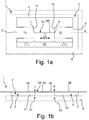
- Fig. 1a shows, for general explanation, a design of a strain measuring arrangement 1 not according to the invention in a plan view, and Figure 1b an associated cross-sectional view, see level Ib in Fig. 1a .
- the strain measuring arrangement 1 comprises a carrier 2, which here comprises an annularly closed, essentially rectangular base element 3 as well as a first carrier part T1 and a second carrier part T2.
- the carrier parts T1, T2 protrude inwards from the base element 3, which forms an outer frame of the carrier 2.
- the carrier 2 is fastened with the frame-shaped base element 3 in a manner not shown on a structure 4 to be monitored, for example glued to the structure 4 with the entire underside of the base element 3; however, the undersides of the carrier pieces T1, T2 are not glued to the structure 4, but only lie on the structure 4.
- the structure 4 to be monitored can be, for example, a railroad track of a train route.
- a strain sensor element 5 is attached to fixing points 7, 8 on the carrier pieces T1 and T2.
- the fixing points 7, 8 are each located at the inner end of the sections T1, T2.
- the central section 5a of the strain sensor element 5 lying between the fixing points 7, 8 is freely stretched here between the sections T1, T2.
- the strain sensor element 5 is designed as an optical fiber 6 with a fiber Bragg grating (also fiber Bragg grating, FBG) 6a in the middle section 5a.
- a fiber Bragg grating also fiber Bragg grating, FBG
- the fiber 6 is shown only in the area of the central section 5a;
- Figure 1b also shows feed lines 6b of the fiber 6.
- other types of strain sensor elements such as electrical resistance measuring strips, can also be used.
- the strain sensor element 5 In a basic state for using the strain sensor element 5 to monitor the strain of the structure 4, the strain sensor element 5 is typically slightly elastically stretched in the middle section 5a in the direction of extension ER of the fiber 6 in order to set the working point of the FBG.
- the elastic expansion of the expansion sensor element 5 can be specified in practically any way during or by the attachment of the expansion sensor element 5 to the fixing points 7, 8 (in the basic state).
- the base element 3 which is attached to the structure 4, is also deformed. This deformation of the base element 3 is transmitted to the strain sensor element 5 via the carrier pieces T1, T2, whereby this deformation can be measured.
- a total length GL of the sections T1, T2 in each case from the rear area 9 to the front area 10, where the respective fixing point 7, 8 is arranged, with GL LT1 + LT2, is here significantly greater than the distance AE of the fixing points 7, 8
- GL 2 * AE;
- GL ⁇ 2 * AE or GL ⁇ 3 * AE is preferred.
- the deformation of the structure 4 or the frame in the direction of extension ER can be increased by the parts T1, T2 protruding parallel to the direction of extension ER of the strain sensor element 5, which move along the direction of extension ER when the structure 4 is deformed, but are hardly deformed themselves are transmitted to the strain sensor element 5, corresponding to the ratio AE / (LT1 + AE + LT2).
- the frame-shaped base element 3 is in an elastically deformed state, in which it is held by the underlying structure 4 on which the base element 3 is attached.
- the base element 3 is stretched slightly elastically with respect to the direction of extension ER. If the base element 3 or the carrier 2 of the Structure 4 should fall off, the elastic deformation of the base element 3 would spring back, so here the base element 3 would contract in the direction of extent ER. This would also change the elastic strain state of the strain sensor element 5, as a result of which the falling off of the structure 4 can be revealed.
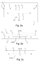
- strain measuring arrangement 1 is shown in plan view in Fig. 2a as well as in side view in Figure 2b in the fastened state on the structure 4 and in Figure 2c shown in the detached state.
- the strain measuring arrangement 1 has a carrier 2 which, in addition to the sections T1, T2, also includes a leaf spring element 21.
- the leaf spring element 21 connects the two carrier pieces T1, T2 to one another, the leaf spring element 21 being fastened with its ends 22, 23 to the sections T1, T2; the end regions of the leaf spring element 21 each overlap the sections T1, T2.
- a support element 24 is formed on the leaf spring element 21, which here engages over the strain sensor element 5 and is supported with a support extension 24a on the structure 4 to be monitored as a stop partner.
- the support element 24 presses the leaf spring element 21 upwards away from the structure 4, whereby the leaf spring element 21 is elastically deformed, namely is stretched here.
- a driver element 25 is formed on the leaf spring element 21, which here likewise engages over the strain sensor element 5 and here has an in Has direction of the strain sensor element 5 to downwardly projecting entrainment extension 25a.
- the driving extension 25a therefore engages behind the strain sensor element 5 from above.
- the entrainment element 25 or its entrainment extension 25a
- the strain sensor element 5 has its normal strain state provided for normal measuring operation (for strain monitoring of the structure 4).
- the leaf spring element 21 springs back into an elastically undeformed state, which is shown in FIG Figure 2c is shown, since the front end of the support element 24 no longer has a stop partner.
- the entrainment extension 25a of the entrainment element 25 presses on the strain sensor element 5 and impresses a strong elastic strain on it. This strong elastic strain can be measured well, so that the drop of the strain measuring arrangement 1 from the structure 4 can easily be recognized.
- the carrier parts T1, T2 or the carrier 2 can be fastened to the structure 4 to be monitored without significant shear stress, which simplifies the assembly.
Landscapes
- Engineering & Computer Science (AREA)
- Mechanical Engineering (AREA)
- Automation & Control Theory (AREA)
- Physics & Mathematics (AREA)
- General Physics & Mathematics (AREA)
- Health & Medical Sciences (AREA)
- Biomedical Technology (AREA)
- General Health & Medical Sciences (AREA)
- Length Measuring Devices By Optical Means (AREA)
- Force Measurement Appropriate To Specific Purposes (AREA)
- Train Traffic Observation, Control, And Security (AREA)
- Measurement Of Length, Angles, Or The Like Using Electric Or Magnetic Means (AREA)
- Investigating Strength Of Materials By Application Of Mechanical Stress (AREA)
- Optical Transform (AREA)
Description
- Die Erfindung betrifft eine Dehnungsmessanordnung, insbesondere für einen Achszähler, umfassend
- wenigstens ein Dehnungssensorelement, insbesondere eine optische Faser mit einem Fiber-Bragg-Gitter,
- einen Träger, auf dem das Dehnungssensorelement befestigt ist, und
- eine zu überwachende Struktur, insbesondere eine Eisenbahnschiene, auf der der Träger befestigt ist, wobei zumindest ein Teil des Trägers im auf der Struktur befestigten Zustand des Trägers durch die Struktur in einem elastisch verformten Zustand gehalten wird,
- Eine solche Dehnungsmessanordnung für einen Achszähler ist insbesondere aus der
DE 10 2015 115 925 B3 bekannt geworden. - Um den Eisenbahnverkehr sicherer zu machen, werden Achszähler eingesetzt. Mit Achszählern kann insbesondere überprüft werden, ob der Ort des Achszählers von einem Zug vollständig passiert wurde, um beispielsweise zu ermitteln, ob zugehörige Gleisabschnitte vollständig frei geworden sind.
- Ein mögliches Messprinzip von Achszählern beruht darauf, eine durch die von einer Achse übertragene Gewichtskraft eines Zuges verursachte elastische Verformung an einer Schiene mit einem Dehnungssensorelement zu messen.
- Die
EP 3 069 952 A1 schlägt dazu vor, als Dehnungssensorelement ein Faser-Bragg-Gitter (=FBG, auch Fiber Bragg Gitter) auf einer Schiene unter einer Vorspannung zu befestigen. Die Reflektionswellenlänge des Faser-Bragg-Gitters ist abhängig vom elastischen Dehnungszustand des FBGs, wodurch der Dehnungszustand vermessen werden kann. Durch die Vorspannung kann am Dehnungszustand des FBGs erkannt werden, ob das FBG noch korrekt an der Schiene befestigt oder von der Schiene abgefallen ist. In einer Variante wird vorgeschlagen, die Vorspannung thermisch aufzubringen, indem ein Träger unter Vorspannung an der Schiene angebracht wird. - Aus der
DE 10 2005 010 344 A1 ist es zudem bekannt, die Dämpfungseigenschaften in einem Lichtwellenleiter über Biegungszustände zu beeinflussen. - Weiterhin sind beispielsweise auch Dehnungssensorelemente bekannt geworden, die auf einer Widerstands- oder Kapazitätsänderung aufgrund eines veränderlichen Dehnungszustands beruhen.
- Das Befestigen von Dehnungssensorelementen unter Vorspannung direkt auf einer zu überwachenden Struktur, etwa einer Eisenbahnschiene, ist jedoch vergleichsweise schwierig. Durch Aufbringung der Vorspannung über einen Träger, auf dem der Dehnungssensor fixiert ist, kann eine gewisse Vereinfachung erzielt werden. Jedoch ist auch in diesem Falle die Einstellung eines bestimmten Dehnungszustands am Dehnungssensorelement (etwa zur Einstellung eines Arbeitspunkts) schwierig.
- Die
DE 10 2015 115 925 B3 beschreibt einen faseroptischen Sensor mit einer Trägerstruktur. Die Trägerstruktur umfasst zwei Befestigungselemente, zwischen denen mit Befestigungspunkten ein Lichtleiter vorgespannt ist. Die Trägerstruktur verfügt über ein auf zwei Seiten bogenförmig ausgebildetes elastisches Element, mit dem in den Lichtleiter in Längsrichtung eine Vorspannung eingebracht wird. Die Trägerstruktur ist über Verbindungsflächen auf einem Zwischenträger befestigt. - Die
EP 1 128 171 A1 beschreibt einen faseroptischen Belastungssensor zur Detektion von Schienenfahrzeugen, wobei eine Lichtleitfaser um eine Stützstruktur aus Stäben geflochten ist. - Der Erfindung liegt die Aufgabe zugrunde, eine einfach zu handhabende Dehnungsmessanordnung vorzustellen, bei der ein Abfallen zuverlässig erkennbar und ein Dehnungszustand des Dehnungssensorelements leichter vorgebbar ist.
- Diese Aufgabe wird gelöst durch eine Dehnungsmessanordnung der eingangs genannten Art, die dadurch gekennzeichnet ist,
dass an dem Blattfederelement ausgebildet ist - ein Stützelement zum Abstützen an der Struktur im auf der Struktur befestigten Zustand des Trägers, wobei im auf der Struktur befestigten Zustand des Trägers das Stützelement das Blattfederelement nach oben von der Struktur wegdrückt, wodurch das Blattfederelement elastisch verformt wird, und
- ein Mitnahmeelement zum Hintergreifen des Dehnungssensorelements im Mittelabschnitt, wobei nach einer Ablösung des Trägers von der Struktur das Blattfederelement in einen elastisch unverformten Zustand zurückfedert und das Mitnahmeelement auf das Dehnungssensorelement drückt und diesem eine elastische Dehnung aufprägt.
- Im Rahmen der Erfindung ist es vorgesehen, das Dehnungssensorelement nicht über seine gesamte Messlänge am Träger linienhaft zu befestigen, sondern das Dehnungssensorelement lediglich mit einem ersten Fixierpunkt an einem ersten Trägerstück, und mit einem zweiten Fixierpunkt an einem zweiten Trägerstück. Im dazwischen liegenden Mittelabschnitt wird das Dehnungssensorelement frei gehalten.
- Dadurch ist es grundsätzlich möglich, den Dehnungszustand des Dehnungssensorelements vom elastischen Verformungszustand des Trägers zumindest teilweise zu entkoppeln. Es wird insbesondere möglich, eine elastische Verformung des Trägers infolge einer Verformung der überwachten Struktur je nach Anwendungsfall abgeschwächt oder verstärkt oder erst ab bestimmten Schwellwerten auf das Dehnungssensorelement zu übertragen, oder bestimmte Arten von Verformung des Trägers verstärkt auf das Dehnungssensorelement zu übertragen. Dadurch kann das
- Dehnungssensorelement in einem optimalen Arbeitsbereich betrieben werden, und bestimmte Überwachungsfunktionen des Dehnungssensorelements, etwa die Erkennung eines Abfallens von der Struktur, können zuverlässiger gemacht werden. Gleichzeitig kann die Befestigung des Trägers an der Struktur mit einer einfach zu beherrschenden elastischen Verformung des Trägers erfolgen, ohne durch das Dehnungssensorelement zu sehr eingeschränkt zu sein.
- Am Mittelabschnitt ist ein einfacher und direkter Zugriff auf das Dehnungssensorelement möglich, insbesondere ohne durch eine Vorformung eines darunter liegenden Trägers in der Verformung des Dehnungssensorelements festgelegt zu sein. Im Mittelabschnitt kann beispielsweise eine zusätzliche Straffung (etwa durch das Mitnahmeelement), oder auch eine zusätzliche Entlastung (etwa durch Überlänge) des Dehnungssensorelements gegenüber dem Träger erfolgen.
- Die Befestigung des Trägers auf der zu überwachenden Struktur, wobei zumindest ein Teil des Trägers durch die Struktur in einem elastisch verformten Zustand gehalten wird, ermöglicht auf einfache Weise eine Kontrolle, ob die Dehnungsmessanordnung noch korrekt an der Struktur sitzt oder von der Struktur abgefallen ist; letzteres führt zu einem Zurückfedern in einen elastisch unverformten Zustand des Trägers bzw. zumindest des besagten Teils. Ein Abfallen von der Struktur kann beispielsweise bei einer Alterung oder temperaturbedingten Erweichung einer Befestigung vorkommen. Bevorzugt ist die Dehnungsmessanordnung so ausgebildet, dass die elastische Verformung bzw. Verspannung des Trägers über eine gemessene Dehnung des Dehnungssensorelements ermittelbar ist (d.h. die elastische Verformung des Trägers liegt im überwachten Bereich des Dehnungssensorelements). Alternativ ist es auch möglich, eine von dem Dehnungssensorelement bzw. dessen Dehnung separate Messeinrichtung bzw. Messung vorzusehen, mit der die Verformung des Trägers überprüft werden kann (etwa unter Verwendung eines weiteres Dehnungssensorelements).
- Meist umfasst eine Dehnungsmessanordnung lediglich ein Dehnungssensorelement, alternativ auch zwei oder noch mehr Dehnungssensorelemente.
- Ein Dehnungssensorelement ist im Rahmen der Erfindung mit einem ersten und zweiten Fixierpunkt an einem ersten und zweiten Trägerstück befestigt sind, und in einem Mittelabschnitt nicht an diesen Trägerstücken (und auch nicht an anderen Teilen des Trägers) befestigt. Der Träger umfasst neben dem ersten und zweiten Trägerstück meist noch ein oder mehrere weitere Teilstücke (etwa ein Grundelement oder eine Spange).
- Das Dehnungssensorelement ist bevorzugt als eine optische Faser mit einem Fiber-Bragg-Gitter (=FBG) ausgebildet; das FBG befindet sich dabei zwischen den Fixierpunkten im Mittelabschnitt. Typischerweise ist das Dehnungssensorelement im auf der Struktur befestigtem Zustand des Trägers unter einer geringen elastischen Dehnung, so dass sowohl Stauchungen als auch Streckungen der zu überwachenden Struktur leicht erkannt werden können.
- Eine erfindungsgemäße Dehnungsmessanordnung kann insbesondere in einem Achszähler verwendet werden; ein solcher Achszähler umfasst wenigstens eine erfindungsgemäße Dehnungsmessanordnung. Es können aber auch andere Anwendungen für die Dehnungsmessanordnung vorgesehen sein, etwa zur Überwachung von mechanischer Belastung oder Verschleiß von Maschinenbauteilen. Ein Dehnungssensorelement kann unter schrägem Winkel, etwa einem Winkel von ca. 45°, zu einer neutralen Faser einer zu überwachenden Struktur angeordnet werden. Die Befestigung des Trägers auf der zu überwachenden Struktur kann beispielsweise durch Verschrauben, Verlöten oder Verkleben erfolgen. Die Befestigung des Dehnungssensorelements an den Trägerstücken kann beispielsweise durch Verklemmen, Verlöten oder Verkleben erfolgen.
- Zusammenfassend ist es mit der Erfindung besonders einfach möglich, zum einen das Dehnungssensorelement (im auf der Struktur befestigten Zustand des Trägers) auf einer gewünschten Vorspannung zu halten, und zum anderen mittels zumindest des Teils des Trägers zu überwachen, ob der Träger noch an der zu überwachenden Struktur (ausreichend) befestigt ist.
- Bei der erfindungsgemäßen Dehnungsmessanordnung ist vorgesehen, dass der Teil des Trägers, der im auf der Struktur befestigten Zustand des Trägers durch die Struktur in einem elastisch verformten Zustand gehalten wird, ein Blattfederelement umfasst,
und dass an dem Blattfederelement ausgebildet ist - ein Stützelement zum Abstützen an der Struktur im auf der Struktur befestigten Zustand des Trägers, und
- ein Mitnahmeelement zum Hintergreifen des Dehnungssensorelements im Mittelabschnitt. Durch das an der Struktur anliegende Stützelement wird dem Blattfederelement eine elastische Verformung aufgeprägt. Das Mitnahmeelement bewegt sich typischerweise im Wesentlichen senkrecht zur Erstreckungsrichtung (Messrichtung) des Dehnungssensorelements und typischerweise im Wesentlichen senkrecht zur Oberfläche der Struktur, an der der Träger befestigt ist. Mit dem Mitnahmeelement kann abhängig von der Verformung des Blattfederelements dem Dehnungssensorelement eine elastische Dehnung oder auch eine Biegung aufgeprägt werden. Diese Dehnung oder Biegung kann durch das Dehnungssensorelement gemessen werden (etwa über die Dehnung als solche, oder auch über eine veränderte, meist erhöhte Dämpfung), und so die Ablösung des Trägers von der Struktur leicht erkannt werden. Die erfindungsgemäße Bauform erkennt eine Ablösung des Dehnungssensorelements von der zu überwachenden Struktur besonders zuverlässig. Zum Erkennen des Sensorabfalls ist lediglich eine elastische Verformung des Blattfederelements notwendig; insbesondere braucht kein Befestigen (etwa Verkleben) von elastisch gegeneinander verspannten Trägerflächen auf der Struktur erfolgen, was die Installation besonders einfach macht.
- Bei einer bevorzugten Ausführungsform der erfindungsgemäßen Dehnungsmessanordnung ist im auf der Struktur befestigten Zustand des Trägers das Mitnahmeelement so weit angehoben, dass dieses das Dehnungssensorelement nicht berührt.
- Bei einer weiteren Ausführungsform sind das Blattfederelement und das Mitnahmeelement so ausgebildet, dass durch diese im elastisch verformten Zustand des Blattfederelements bei auf der Struktur befestigtem Träger auf das Dehnungssensorelement keine oder nur eine geringe Dehnung aufgeprägt wird, und in einem elastisch entspannten Zustand des Blattfederelements nach einer Ablösung des Trägers von der Struktur auf das Dehnungssensorelement eine größere Dehnung aufgeprägt wird. Das Blattfederelement (zusammen mit dem Mitnahmeelement) strafft und/oder verbiegt in seinem elastisch entspannten Zustand das Dehnungssensorelement, was in der Regel leicht zu detektieren ist; umgekehrt sind das Blattfederelement und das Mitnahmeelement (sowie das Stützelement) so ausgebildet, dass im elastisch verspannten Zustand das Dehnungssensorelement vom Mitnahmeelement nicht oder nur wenig gestrafft wird. Es ist alternativ auch möglich, das Dehnungssensorelement im elastisch entspannten Zustand des Blattfederelements zu entspannen.
- Bevorzugt ist zudem eine Ausführungsform, die vorsieht, dass das Mitnahmeelement einen auf das Dehnungssensorelement zu nach unten ragenden Mitnahmefortsatz aufweist, und dass in dem elastisch unverformten Zustand des Blattfederelements das Mitnahmeelement mit dem Mitnahmefortsatz auf das Dehnungssensorelement drückt.
- Bevorzugt ist auch eine Ausführungsform, die vorsieht,
- dass der Träger ein Grundelement aufweist, mit dem der Träger an der zu überwachenden Struktur befestigt ist,
- und dass das erste Trägerstück und das zweite Trägerstück auf oder an dem Grundelement befestigt sind. Über das Grundelement kann eine gezielte und vereinfachte Befestigung an der Struktur erfolgen, insbesondere auch flächig. Die Trägerstücke sind in der Regel lediglich über das Grundelement auf der Struktur befestigt. Eine typische Grundstruktur ist als ein geschlossener Ring ("Rahmen") ausgebildet, und die Trägerstücken ragen nach innen in den Ring ein. Eine andere typische Grundstruktur ist mit einer geschlossenen Fläche ausgebildet, auf der die Trägerstücke aufsitzen.
- Eine bevorzugte Weiterbildung dieser Ausführungsform sieht vor, dass das erste und zweite Trägerstück jeweils lediglich in einem hinteren Bereich, der dem Dehnungssensorelement abgewandt ist, am Grundelement befestigt sind, und dass das erste und zweite Trägerstück jeweils in einem vorderen Bereich, der dem hinteren Bereich abgewandt ist, am Dehnungssensorelement befestigt sind. Die Trägerstücke sind lediglich über das Grundelement auf der Struktur befestigt, wobei die Befestigung am hinteren Bereich des jeweiligen Trägerstücks erfolgt. Die Trägerstücke zeigen (zwischen vorderem und hinterem Bereich) typischerweise keine merkliche elastische Verformung. Durch den Abstand von vorderem Bereich und hinterem Bereich wird die elastische Dehnung des Grundkörpers bzw. der Struktur verstärkt auf das Dehnungssensorelement übertragen. Typischerweise ist die gesamte Länge GL der Trägerstücke zwischen vorderem und hinterem Bereich wenigstens dreimal so groß wie die Länge AE des Dehnungssensorelements zwischen den Fixierpunkten.
- Weitere Vorteile der Erfindung ergeben sich aus der Beschreibung und der Zeichnung. Ebenso können die vorstehend genannten und die noch weiter ausgeführten Merkmale erfindungsgemäß jeweils einzeln für sich oder zu mehreren in beliebigen Kombinationen Verwendung finden. Die gezeigten und beschriebenen Ausführungsformen sind nicht als abschließende Aufzählung zu verstehen, sondern haben vielmehr beispielhaften Charakter für die Schilderung der Erfindung.
- Die Erfindung ist in der Zeichnung dargestellt und wird anhand von Ausführungsbeispielen näher erläutert. Es zeigen:
- Fig. 1a
- eine schematische Aufsicht auf eine Bauform einer nicht erfindungsgemäßen Dehnungsmessanordnung, mit rahmenförmigem Grundelement, zur allgemeinen Erläuterung;
- Fig. 1b
- eine schematische Querschnittsansicht der Dehnungsmessanordnung von
Fig. 1a ; - Fig. 2a
- eine schematische Aufsicht auf eine Ausführungsform einer erfindungsgemäßen Dehnungsmessanordnung, mit Blattfederelement, Stützelement und Mitnahmeelement;
- Fig. 2b
- eine schematische Seitenansicht der Dehnungsmessanordnung von
Fig. 2a , mit auf der Struktur befestigtem Träger; - Fig. 2c
- eine schematische Seitenansicht der Dehnungsmessanordnung von
Fig. 2a , mit von der Struktur abgelöstem Träger. - Die
Fig. 1a zeigt zur allgemeinen Erläuterung eine Bauform einer nicht erfindungsgemäßen Dehnungsmessanordnung 1 in einer Aufsicht, undFig. 1b eine zugehörige Querschnittsansicht, vgl. Ebene Ib inFig. 1a . - Die Dehnungsmessanordnung 1 umfasst einen Träger 2, der hier ein ringförmig geschlossenes, im Wesentlichen rechteckiges Grundelement 3 sowie ein erstes Trägerteil T1 und ein zweites Trägerteil T2 umfasst. Die Trägerteile T1, T2 stehen nach innen vom Grundelement 3 ab, welches einen äußeren Rahmen des Trägers 2 ausbildet.
- Der Träger 2 ist mit dem rahmenförmigen Grundelement 3 in nicht näher dargestellter Weise auf einer zu überwachenden Struktur 4 befestigt, beispielsweise mit der gesamten Unterseite des Grundelements 3 auf der Struktur 4 aufgeklebt; die Unterseiten der Trägerstücke T1, T2 sind jedoch nicht auf der Struktur 4 aufgeklebt, sondern liegen nur auf der Struktur 4 auf. Die zu überwachende Struktur 4 kann beispielsweise eine Eisenbahnschiene einer Zugfahrstrecke sein.
- Auf den Trägerstücken T1 und T2 ist ein Dehnungssensorelement 5 an Fixierpunkten 7, 8 befestigt. Die Fixierpunkte 7, 8 liegen jeweils am inneren Ende der Teilstücke T1, T2. Der zwischen den Fixierpunkten 7, 8 liegende Mittelabschnitt 5a des Dehnungssensorelements 5 ist hier zwischen den Teilstücken T1, T2 frei gespannt.
- In der gezeigten Bauform ist das Dehnungssensorelement 5 als eine optische Faser 6 mit einem Fiber-Bragg-Gitter (auch Faser Bragg Gitter, FBG) 6a im Mittelabschnitt 5a ausgebildet. Man beachte, dass in
Fig. 1a zur Vereinfachung die Faser 6 nur im Bereich des Mittelabschnitts 5a dargestellt ist;Fig. 1b zeigt auch Zuleitungen 6b der Faser 6. Alternativ können auch andere Dehnungssensorelement-Typen, etwa elektrische Widerstandsmessstreifen, eingesetzt werden. - In einem Grundzustand für die Verwendung des Dehnungssensorelements 5 zur Überwachung der Dehnung der Struktur 4 ist das Dehnungssensorelement 5 typischerweise im Mittelabschnitt 5a in Erstreckungsrichtung ER der Faser 6 geringfügig elastisch gedehnt, um den Arbeitspunkt des FBGs einzustellen. Die elastische Dehnung des Dehnungssensorelements 5 kann dabei bei der bzw. durch die Befestigung des Dehnungssensorelements 5 an den Fixierpunkten 7, 8 (im Grundzustand) praktisch beliebig vorgegeben werden.
- Verformt sich die Struktur 4, so wird auch das Grundelement 3, das auf der Struktur 4 befestigt ist, mit verformt. Diese Verformung des Grundelements 3 wird über die Trägerstücke T1, T2 auf das Dehnungssensorelement 5 übertragen, wodurch diese Verformung messbar wird.
- Eine gesamte Länge GL der Teilstücke T1, T2 jeweils vom hinteren Bereich 9 bis zum vorderen Bereich 10, wo der jeweilige Fixierpunkt 7, 8 angeordnet ist, mit GL=LT1+LT2, ist hier deutlich größer als der Abstand AE der Fixierpunkte 7, 8. In der gezeigten Bauform gilt näherungsweise GL=2*AE; im allgemeinen ist GL≥2*AE oder auch GL≥3*AE bevorzugt. Durch die parallel zur Erstreckungsrichtung ER des Dehnungssensorelements 5 hervorstehenden Teilstücke T1, T2, die die bei Verformung der Struktur 4 entlang der Erstreckungsrichtung ER sich zwar bewegen, aber selbst kaum verformt werden, kann die Verformung der Struktur 4 bzw. des Rahmens in Erstreckungsrichtung ER verstärkt auf das Dehnungssensorelement 5 übertragen werden, entsprechend dem Verhältnis AE/(LT1+AE+LT2).
- Im bereits erwähnten Grundzustand ist das rahmenförmige Grundelement 3 in einem elastisch verformten Zustand, in welchem es durch die darunter liegende Struktur 4, auf der das Grundelement 3 befestigt ist, gehalten wird. Vorliegend ist das Grundelement 3 bezüglich der Erstreckungsrichtung ER geringfügig elastisch gestreckt. Falls das Grundelement 3 bzw. der Träger 2 von der Struktur 4 abfallen sollte, würde die elastische Verformung des Grundelements 3 zurückfedern, hier also sich das Grundelement 3 in Erstreckungsrichtung ER zusammenziehen. Dadurch würde auch der elastische Dehnungszustand des Dehnungssensorelements 5 verändert, wodurch das Abfallen von der Struktur 4 aufgedeckt werden kann.
- In der nachfolgend beschriebenen Ausführungsform der erfindungsgemäßen Dehnungsmessanordnung werden vor allem die Unterschiede zur Bauform von
Fig. 1a, 1b erläutert. - Die Ausführungsform einer erfindungsgemäßen Dehnungsmessanordnung 1 ist in Aufsicht in
Fig. 2a sowie in Seitenansicht inFig. 2b im befestigten Zustand auf der Struktur 4 und inFig. 2c im abgelösten Zustand dargestellt. - Die Dehnungsmessanordnung 1 verfügt über einen Träger 2, der neben den Teilstücken T1, T2 weiterhin ein Blattfederelement 21 umfasst. In der gezeigten Ausführungsform verbindet das Blattfederelement 21 die beiden Trägerstücke T1, T2 miteinander, wobei das Blattfederelement 21 mit seinen Enden 22, 23 jeweils an den Teilstücken T1, T2 befestigt ist; die Endbereiche des Blattfederelements 21 übergreifen jeweils die Teilstücke T1, T2.
- Am Blattfederelement 21 ist ein Stützelement 24 ausgebildet, welches hier das Dehnungssensorelement 5 übergreift und sich mit einem Stützfortsatz 24a auf der zu überwachenden Struktur 4 als Anschlagpartner abstützt. Im auf der Struktur 4 befestigten Zustand (vgl.
Fig. 2b ) des Trägers 2 drückt dabei das Stützelement 24 das Blattfederelement 21 nach oben von der Struktur 4 weg, wodurch das Blattfederelement 21 elastisch verformt, nämlich hier gedehnt wird. - Am Blattfederelement 21 ist zudem ein Mitnahmeelement 25 ausgebildet, das hier ebenfalls das Dehnungssensorelement 5 übergreift und hier einen in Richtung auf das Dehnungssensorelement 5 zu nach unten ragenden Mitnahmefortsatz 25a aufweist. Der Mitnahmefortsatz 25a hintergreift das Dehnungssensorelement 5 also von oben. Im durch die Abstützung auf der Struktur 4 elastisch verformten Zustand des Blattfederelements 21 (vgl.
Fig. 2b ) ist in der gezeigten Ausführungsform das Mitnahmeelement 25 (bzw. dessen Mitnahmefortsatz 25a) so weit angehoben, dass dieses das Dehnungssensorelement 5 nicht berührt. Entsprechend hat das Dehnungssensorelement 5 seinen für den normalen Messbetrieb (zur Dehnungsüberwachung der Struktur 4) vorgesehenen, normalen Dehnungszustand. - Falls die Dehnungsmessanordnung 1 von der Struktur 4 abfallen sollte, so federt das Blattfederelement 21 in einen elastisch unverformten Zustand zurück, der in
Fig. 2c gezeigt ist, da das Stützelement 24 vorderenends keinen Anschlagpartner mehr hat. In diesem Zustand drückt der Mitnahmefortsatz 25a des Mitnahmeelements 25 auf das Dehnungssensorelement 5 und prägt diesem eine starke elastische Dehnung auf. Diese starke elastische Dehnung ist gut zu vermessen, wodurch das Abfallen der Dehnungsmessanordnung 1 von der Struktur 4 leicht erkannt werden kann. - Bei der Ausführungsform von
Fig. 2a-2c können die Trägerteile T1, T2 bzw. der Träger 2 ohne nennenswerte Scherspannung auf der zu überwachenden Struktur 4 befestigt werden, was die Montage vereinfacht. -
- 1
- Dehnungsmessanordnung
- 2
- Träger
- 3
- Grundelement
- 4
- zu überwachende Struktur
- 5
- Dehnungssensorelement
- 5a
- Mittelabschnitt
- 6
- optische Faser
- 6a
- Fiber-Bragg-Gitter
- 6b
- Zuleitung
- 7
- erster Fixierpunkt
- 8
- zweiter Fixierpunkt
- 9
- hinterer Bereich
- 10
- vorderer Bereich
- 21
- Blattfederelement
- 22
- Ende (Blattfederelement)
- 23
- Ende (Blattfederelement)
- 24
- Stützelement
- 24a
- Stützfortsatz
- 25
- Mitnahmeelement
- 25a
- Mitnehmerfortsatz
- AE
- Abstand Fixierpunkte
- ER
- Erstreckungsrichtung (Dehnungssensorelement)
- GL
- gesamte Länge Teilstücke T1, T2
- FBG
- Fiber Bragg Gitter (Faser Bragg Gitter)
- LT1
- Länge Teilstück T1
- LT2
- Länge Teilstück T2
- T1
- erstes Teilstück (Dehnungssensorelement)
- T2
- zweites Teilstück (Dehnungssensorelement)
wobei der Teil des Trägers, der im auf der Struktur befestigten Zustand des Trägers durch die Struktur in einem elastisch verformten Zustand gehalten wird, ein Blattfederelement umfasst.
Claims (4)
- Dehnungsmessanordnung (1), insbesondere für einen Achszähler (91), umfassend- wenigstens ein Dehnungssensorelement (5), insbesondere eine optische Faser (6) mit einem Fiber-Bragg-Gitter (6a, FBG),- einen Träger (2), auf dem das Dehnungssensorelement (5) befestigt ist, und- eine zu überwachende Struktur (4), insbesondere eine Eisenbahnschiene, auf der der Träger (2) befestigt ist, wobei zumindest ein Teil des Trägers (2) im auf der Struktur (4) befestigten Zustand des Trägers (2) durch die Struktur (4) in einem elastisch verformten Zustand gehalten wird,wobei der Träger (2) ausgebildet ist mit einem ersten Trägerstück (T1) und einen zweiten Trägerstück (T2), die voneinander beabstandet einander gegenüberliegen,wobei das Dehnungssensorelement (5) zumindest mit einem ersten Fixierpunkt (7) am ersten Trägerstück (T1), und zumindest mit einem zweiten Fixierpunkt (8) am zweiten Trägerstück (T2), und mit einem Mittelabschnitt (5a) zwischen den Fixierpunkten (7, 8) weder am ersten noch am zweiten Trägerstück (T1, T2) befestigt ist,wobei der Teil des Trägers (2), der im auf der Struktur (4) befestigten Zustand des Trägers (2) durch die Struktur (4) in einem elastisch verformten Zustand gehalten wird, ein Blattfederelement (21) umfasst,dadurch gekennzeichnet,dass an dem Blattfederelement (21) ausgebildet ist- ein Stützelement (24) zum Abstützen an der Struktur (4) im auf der Struktur (4) befestigten Zustand des Trägers (2), wobei im auf der Struktur (4) befestigten Zustand des Trägers (2) das Stützelement (24) das Blattfederelement (21) nach oben von der Struktur (4) wegdrückt, wodurch das Blattfederelement (21) elastisch verformt wird, und- ein Mitnahmeelement (25) zum Hintergreifen des Dehnungssensorelements (5) im Mittelabschnitt (5a), wobei nach einer Ablösung des Trägers (2) von der Struktur (4) das Blattfederelement (21) in einen elastisch unverformten Zustand zurückfedert und das Mitnahmeelement (25) auf das Dehnungssensorelement (5) drückt und diesem eine elastische Dehnung aufprägt.
- Anordnung (1) nach Anspruch 1, dadurch gekennzeichnet,
dass im auf der Struktur (4) befestigten Zustand des Trägers (2) das Mitnahmeelement (25) so weit angehoben ist, dass dieses das Dehnungssensorelement (5) nicht berührt. - Anordnung (1) nach Anspruch 1 oder 2, dadurch gekennzeichnet, dass das Blattfederelement (21) und das Mitnahmeelement (25) so ausgebildet sind, dass durch diese im elastisch verformten Zustand des Blattfederelements (21) bei auf der Struktur (4) befestigtem Träger (2) auf das Dehnungssensorelement (5) keine oder nur eine geringe Dehnung aufprägt wird, und in einem elastisch entspannten Zustand des Blattfederelements (21) nach einer Ablösung des Trägers (2) von der Struktur (4) auf das Dehnungssensorelement (5) eine größere Dehnung aufgeprägt wird.
- Anordnung nach einem der Ansprüche 1 bis 3, dadurch gekennzeichnet, dass das Mitnahmeelement (25) einen auf das Dehnungssensorelement (5) zu nach unten ragenden Mitnahmefortsatz (25a) aufweist, und dass in dem elastisch unverformten Zustand des Blattfederelements (21) das Mitnahmeelement (25) mit dem Mitnahmefortsatz (25a) auf das Dehnungssensorelement (5) drückt.
Priority Applications (4)
| Application Number | Priority Date | Filing Date | Title |
|---|---|---|---|
| SI201830524T SI3684672T1 (sl) | 2017-09-22 | 2018-09-05 | Razporeditev za merjenje raztezka, zlasti za števec osi |
| PL18759979T PL3684672T3 (pl) | 2017-09-22 | 2018-09-05 | Układ pomiaru odkształcenia, w szczególności do licznika osi |
| HRP20220038TT HRP20220038T1 (hr) | 2017-09-22 | 2018-09-05 | Sklop za mjerenje naprezanja, posebice za brojač osovina |
| RS20211585A RS62757B1 (sr) | 2017-09-22 | 2018-09-05 | Sklop za merenje naprezanja, posebno za brojač osovina |
Applications Claiming Priority (2)
| Application Number | Priority Date | Filing Date | Title |
|---|---|---|---|
| EP17192644.7A EP3459811B1 (de) | 2017-09-22 | 2017-09-22 | Verfahren zur montage einer dehnungsmessanordnung, insbesondere für einen achszähler, und zugehörige verwendung |
| PCT/EP2018/073820 WO2019057491A1 (de) | 2017-09-22 | 2018-09-05 | Dehnungsmessanordnung, insbesondere für einen achszähler |
Publications (2)
| Publication Number | Publication Date |
|---|---|
| EP3684672A1 EP3684672A1 (de) | 2020-07-29 |
| EP3684672B1 true EP3684672B1 (de) | 2021-10-20 |
Family
ID=59982276
Family Applications (2)
| Application Number | Title | Priority Date | Filing Date |
|---|---|---|---|
| EP17192644.7A Active EP3459811B1 (de) | 2017-09-22 | 2017-09-22 | Verfahren zur montage einer dehnungsmessanordnung, insbesondere für einen achszähler, und zugehörige verwendung |
| EP18759979.0A Active EP3684672B1 (de) | 2017-09-22 | 2018-09-05 | Dehnungsmessanordnung, insbesondere für einen achszähler |
Family Applications Before (1)
| Application Number | Title | Priority Date | Filing Date |
|---|---|---|---|
| EP17192644.7A Active EP3459811B1 (de) | 2017-09-22 | 2017-09-22 | Verfahren zur montage einer dehnungsmessanordnung, insbesondere für einen achszähler, und zugehörige verwendung |
Country Status (19)
| Country | Link |
|---|---|
| US (2) | US10926782B2 (de) |
| EP (2) | EP3459811B1 (de) |
| JP (2) | JP6827590B2 (de) |
| KR (1) | KR102163395B1 (de) |
| CN (2) | CN112880579B (de) |
| AU (2) | AU2018336680B2 (de) |
| CA (1) | CA3076559C (de) |
| DK (2) | DK3459811T3 (de) |
| ES (2) | ES2903128T3 (de) |
| HR (2) | HRP20220030T1 (de) |
| HU (2) | HUE057532T2 (de) |
| IL (2) | IL273438B (de) |
| MA (1) | MA50153B1 (de) |
| PL (2) | PL3459811T3 (de) |
| PT (2) | PT3459811T (de) |
| RS (2) | RS62762B1 (de) |
| SI (2) | SI3459811T1 (de) |
| WO (1) | WO2019057491A1 (de) |
| ZA (1) | ZA202001471B (de) |
Families Citing this family (6)
| Publication number | Priority date | Publication date | Assignee | Title |
|---|---|---|---|---|
| PT3835166T (pt) | 2019-12-12 | 2022-11-16 | Thales Man & Services Deutschland Gmbh | Elemento de contacto com um carril e unidade de deteção de queda |
| MA53295B1 (fr) | 2019-12-12 | 2022-07-29 | Thales Man & Services Deutschland Gmbh | Élément de fixation, unité de capteur dotée d'un capteur et d'un élément de fixation, unité de capteur et procédé de fixation d'une unité de capteur |
| CN112683187B (zh) * | 2020-11-26 | 2022-06-03 | 中国兵器工业第五九研究所 | 一种光纤光栅应变检测装置 |
| CN113264084A (zh) * | 2021-05-27 | 2021-08-17 | 海宁德科隆电子有限公司 | 轨道计轴传感器 |
| JP7752995B2 (ja) * | 2021-08-19 | 2025-10-14 | 阪神高速技術株式会社 | 構造物用線状部材の張力検出方法、構造物用線状部材及び線状部材用センサ設置治具 |
| CN117533368B (zh) * | 2023-12-21 | 2025-09-09 | 通号(西安)轨道交通工业集团有限公司北京分公司 | 一种车轮传感器和车轮传感器的脱落检测装置、方法和系统 |
Family Cites Families (28)
| Publication number | Priority date | Publication date | Assignee | Title |
|---|---|---|---|---|
| DE3815152A1 (de) * | 1988-05-04 | 1989-11-23 | Strabag Bau Ag | Einrichtung zum ueberwachen und/oder steuern eines schienengebundenen verkehrs |
| JP3492943B2 (ja) * | 1999-07-07 | 2004-02-03 | 日本電信電話株式会社 | 光ファイバセンサによる剥離検出方法 |
| WO2001035133A1 (en) * | 1999-11-11 | 2001-05-17 | Koheras A/S | Compact athermal optical waveguide using thermal expansion amplification |
| EP1128171A1 (de) * | 2000-02-22 | 2001-08-29 | Sensor Line Gesellschaft für optoelektronische Sensoren mbH | Faseroptischer Belastungssensor zur Detektion von Schienenfahrzeugen |
| JP2002286563A (ja) | 2001-03-28 | 2002-10-03 | Kyowa Electron Instr Co Ltd | 光ファイバ式ひずみゲージ |
| JP3598297B2 (ja) * | 2002-03-27 | 2004-12-08 | 株式会社東京測器研究所 | Fbg式変換器における温度補償構造 |
| EP2351680B1 (de) * | 2004-03-29 | 2012-12-12 | The Hong Kong Polytechnic University | System und Verfahren zur Überwachung von Eisenbahnstrecken |
| JP2005055450A (ja) * | 2004-11-29 | 2005-03-03 | Kyowa Electron Instr Co Ltd | 光ファイバ式ひずみゲージ |
| JP2006201071A (ja) * | 2005-01-21 | 2006-08-03 | Mitsubishi Electric Corp | 光ファイバ式荷重センサおよびそれを用いた侵入者検知システム |
| DE102005010344B4 (de) | 2005-03-07 | 2007-05-31 | CCS Technology, Inc., Wilmington | Vorrichtung zum Biegen eines Lichtwellenleiters sowie Anordnung zum Dämpfen von Licht in einem Lichtwellenleiter |
| US20070193362A1 (en) * | 2006-02-06 | 2007-08-23 | Ferguson Stephen K | Fiber optic strain gage |
| JP5155702B2 (ja) * | 2008-03-13 | 2013-03-06 | アンリツ株式会社 | 歪計測装置 |
| JP2010054359A (ja) * | 2008-08-28 | 2010-03-11 | Honda Motor Co Ltd | 光ファイバセンサ |
| CN201266078Y (zh) * | 2008-07-18 | 2009-07-01 | 中冶建筑研究总院有限公司 | 一种光纤光栅应变传感器 |
| US7796844B2 (en) | 2008-07-22 | 2010-09-14 | The Hong Kong Polytechnic University | Temperature-compensated fibre optic strain gauge |
| CN103465934B (zh) * | 2009-11-30 | 2015-09-02 | 同方威视技术股份有限公司 | 铁路落石预警方法 |
| GB201201703D0 (en) * | 2012-02-01 | 2012-03-14 | Qinetiq Ltd | Detecting train separation |
| GB201203273D0 (en) * | 2012-02-24 | 2012-04-11 | Qinetiq Ltd | Monitoring transport network infrastructure |
| US10069494B2 (en) * | 2013-03-08 | 2018-09-04 | Safran Landing Systems Canada Inc./Safran Systemes D'atterrissage Canada Inc. | Proximity sensor |
| CN103673914B (zh) * | 2013-12-13 | 2016-06-01 | 北京航天时代光电科技有限公司 | 一种光纤光栅应变传感器及其安装方法 |
| DE102014100653B4 (de) * | 2014-01-21 | 2016-01-21 | fos4X GmbH | Schienenmesssystem |
| EP3069952B1 (de) | 2015-03-20 | 2017-05-03 | Thales Deutschland GmbH | Achszählverfahren und achszählvorrichtung |
| JP6736044B2 (ja) * | 2015-05-15 | 2020-08-05 | 株式会社シミウス | 歪みセンサ及び歪みセンサの取付治具 |
| DE102015115927A1 (de) | 2015-09-21 | 2017-04-06 | fos4X GmbH | Sensorpatch und Verfahren zum Herstellen eines Sensorpatches |
| DE102015115925B3 (de) * | 2015-09-21 | 2016-12-08 | fos4X GmbH | Lichtleiter-Einspannvorrichtung, faseroptischer Sensor und Herstellungsverfahren |
| CN105258716B (zh) * | 2015-09-30 | 2017-10-31 | 南京航空航天大学 | L形光纤光栅传感器及其应用 |
| CN106441140A (zh) * | 2016-10-25 | 2017-02-22 | 武汉理工大学 | 一种光纤光栅应变增敏传感器 |
| CN106501165B (zh) * | 2016-11-09 | 2023-12-29 | 河海大学 | 温度自补偿光纤光栅钢筋锈蚀传感器及其温度补偿方法 |
-
2017
- 2017-09-22 ES ES17192644T patent/ES2903128T3/es active Active
- 2017-09-22 DK DK17192644.7T patent/DK3459811T3/da active
- 2017-09-22 HU HUE17192644A patent/HUE057532T2/hu unknown
- 2017-09-22 SI SI201731038T patent/SI3459811T1/sl unknown
- 2017-09-22 PL PL17192644T patent/PL3459811T3/pl unknown
- 2017-09-22 RS RS20211598A patent/RS62762B1/sr unknown
- 2017-09-22 PT PT171926447T patent/PT3459811T/pt unknown
- 2017-09-22 EP EP17192644.7A patent/EP3459811B1/de active Active
- 2017-09-22 HR HRP20220030TT patent/HRP20220030T1/hr unknown
-
2018
- 2018-09-05 KR KR1020207011367A patent/KR102163395B1/ko active Active
- 2018-09-05 JP JP2020516529A patent/JP6827590B2/ja active Active
- 2018-09-05 PT PT187599790T patent/PT3684672T/pt unknown
- 2018-09-05 SI SI201830524T patent/SI3684672T1/sl unknown
- 2018-09-05 PL PL18759979T patent/PL3684672T3/pl unknown
- 2018-09-05 CN CN202110041158.3A patent/CN112880579B/zh active Active
- 2018-09-05 RS RS20211585A patent/RS62757B1/sr unknown
- 2018-09-05 CN CN201880061096.9A patent/CN111108033B/zh active Active
- 2018-09-05 ES ES18759979T patent/ES2903478T3/es active Active
- 2018-09-05 HU HUE18759979A patent/HUE057507T2/hu unknown
- 2018-09-05 WO PCT/EP2018/073820 patent/WO2019057491A1/de not_active Ceased
- 2018-09-05 AU AU2018336680A patent/AU2018336680B2/en active Active
- 2018-09-05 HR HRP20220038TT patent/HRP20220038T1/hr unknown
- 2018-09-05 MA MA50153A patent/MA50153B1/fr unknown
- 2018-09-05 CA CA3076559A patent/CA3076559C/en active Active
- 2018-09-05 DK DK18759979.0T patent/DK3684672T3/da active
- 2018-09-05 EP EP18759979.0A patent/EP3684672B1/de active Active
-
2020
- 2020-03-09 ZA ZA2020/01471A patent/ZA202001471B/en unknown
- 2020-03-19 IL IL273438A patent/IL273438B/en active IP Right Grant
- 2020-03-21 US US16/826,220 patent/US10926782B2/en active Active
-
2021
- 2021-01-18 JP JP2021005691A patent/JP7248714B2/ja active Active
- 2021-01-22 US US17/248,406 patent/US11345376B2/en active Active
- 2021-02-12 AU AU2021200912A patent/AU2021200912B2/en active Active
- 2021-03-04 IL IL281271A patent/IL281271B/en unknown
Also Published As
Similar Documents
| Publication | Publication Date | Title |
|---|---|---|
| EP3459811B1 (de) | Verfahren zur montage einer dehnungsmessanordnung, insbesondere für einen achszähler, und zugehörige verwendung | |
| DE102013110750B3 (de) | Optische Baugruppe mit einer Fassung mit thermisch abhängigem Kraftausgleich | |
| WO2013156607A1 (de) | Überwachungssystem für zug- und druckkräfte in einer energieführungskette und entsprechender kraftaufnehmer | |
| EP0754135B1 (de) | Feststellbremse für kraftfahrzeuge, fahrzeuganhänger oder dergleichen | |
| DE3516234A1 (de) | Einrichtung zum messen von kraeften und drehmomenten in verschiedenen richtungen | |
| EP4141282B1 (de) | Scheibenbremse für ein kraftfahrzeug | |
| EP1979729B1 (de) | Verfahren zur kontinuierlichen bestimmung der zugkraft f in einem seil einer feststellbremse | |
| DE3737733C1 (en) | Window lift for a motor vehicle | |
| EP0732476A1 (de) | Antriebseinrichtung | |
| DE102012013966A1 (de) | Scheibenbremse für ein Nutzfahrzeug | |
| EP0431382B1 (de) | Zuspanngestänge für Scheibenbremsen | |
| EP0793028A1 (de) | Vorrichtung für einem Seillängenausgleich bei Bowdenrohr-Fensterhebern | |
| DE102017101833A1 (de) | Fugenüberbrückungseinrichtung | |
| DE102017108218B4 (de) | Höhenverstelleinrichtung eines Kraftfahrzeugsitzes sowie Verfahren zur Herstellung einer derartigen Höhenverstelleinrichtung | |
| DE102008011200A1 (de) | Verbundprofil, insbesondere für ein Fenster-, Tür- oder Fassadensystem | |
| DE102007014534A1 (de) | Dachintegrationsmodul | |
| EP1798098A1 (de) | Fahrpedal für Fahrzeuge | |
| EP3502629A1 (de) | System und verfahren zur überwachung des anpressdrucks einer kraft- und/oder formschlüssigen verbindung | |
| DE102013017708A1 (de) | Torsionsfederelement | |
| WO2000003218A1 (de) | Kraftmesszelle | |
| EP3581825B1 (de) | Lagereinrichtung, solaranlagenanordnung | |
| DE3444235C2 (de) | ||
| EP3487725B1 (de) | Federbaugruppe für einen entriegelungsmechanismus einer längsverstellung eines fahrzeugsitzes und verfahren zur montage einer federbaugruppe | |
| DE102014107224A1 (de) | Scheibenbremse für ein Nutzfahrzeug | |
| DE7735462U1 (de) | Aufhängevorrichtung für Mehrfach-Abspannisolatorenketten |
Legal Events
| Date | Code | Title | Description |
|---|---|---|---|
| REG | Reference to a national code |
Ref country code: HR Ref legal event code: TUEP Ref document number: P20220038 Country of ref document: HR |
|
| STAA | Information on the status of an ep patent application or granted ep patent |
Free format text: STATUS: UNKNOWN |
|
| STAA | Information on the status of an ep patent application or granted ep patent |
Free format text: STATUS: THE INTERNATIONAL PUBLICATION HAS BEEN MADE |
|
| PUAI | Public reference made under article 153(3) epc to a published international application that has entered the european phase |
Free format text: ORIGINAL CODE: 0009012 |
|
| STAA | Information on the status of an ep patent application or granted ep patent |
Free format text: STATUS: REQUEST FOR EXAMINATION WAS MADE |
|
| 17P | Request for examination filed |
Effective date: 20200422 |
|
| AK | Designated contracting states |
Kind code of ref document: A1 Designated state(s): AL AT BE BG CH CY CZ DE DK EE ES FI FR GB GR HR HU IE IS IT LI LT LU LV MC MK MT NL NO PL PT RO RS SE SI SK SM TR |
|
| AX | Request for extension of the european patent |
Extension state: BA ME |
|
| RAV | Requested validation state of the european patent: fee paid |
Extension state: MA Effective date: 20200422 |
|
| RAX | Requested extension states of the european patent have changed |
Extension state: BA Payment date: 20200422 |
|
| GRAP | Despatch of communication of intention to grant a patent |
Free format text: ORIGINAL CODE: EPIDOSNIGR1 |
|
| STAA | Information on the status of an ep patent application or granted ep patent |
Free format text: STATUS: GRANT OF PATENT IS INTENDED |
|
| INTG | Intention to grant announced |
Effective date: 20210517 |
|
| GRAS | Grant fee paid |
Free format text: ORIGINAL CODE: EPIDOSNIGR3 |
|
| RIN1 | Information on inventor provided before grant (corrected) |
Inventor name: HOFFMANN, LARS Inventor name: MUSCHAWECKH, FLORIAN Inventor name: KLEMM, RAINER Inventor name: OLDEWURTEL, KASSEN Inventor name: SCHICKER, KAI |
|
| GRAA | (expected) grant |
Free format text: ORIGINAL CODE: 0009210 |
|
| STAA | Information on the status of an ep patent application or granted ep patent |
Free format text: STATUS: THE PATENT HAS BEEN GRANTED |
|
| AK | Designated contracting states |
Kind code of ref document: B1 Designated state(s): AL AT BE BG CH CY CZ DE DK EE ES FI FR GB GR HR HU IE IS IT LI LT LU LV MC MK MT NL NO PL PT RO RS SE SI SK SM TR |
|
| REG | Reference to a national code |
Ref country code: GB Ref legal event code: FG4D Free format text: NOT ENGLISH |
|
| REG | Reference to a national code |
Ref country code: CH Ref legal event code: EP |
|
| REG | Reference to a national code |
Ref country code: IE Ref legal event code: FG4D Free format text: LANGUAGE OF EP DOCUMENT: GERMAN |
|
| REG | Reference to a national code |
Ref country code: DE Ref legal event code: R096 Ref document number: 502018007524 Country of ref document: DE |
|
| REG | Reference to a national code |
Ref country code: AT Ref legal event code: REF Ref document number: 1439712 Country of ref document: AT Kind code of ref document: T Effective date: 20211115 |
|
| REG | Reference to a national code |
Ref country code: FI Ref legal event code: FGE |
|
| REG | Reference to a national code |
Ref country code: PT Ref legal event code: SC4A Ref document number: 3684672 Country of ref document: PT Date of ref document: 20220111 Kind code of ref document: T Free format text: AVAILABILITY OF NATIONAL TRANSLATION Effective date: 20220105 |
|
| REG | Reference to a national code |
Ref country code: DK Ref legal event code: T3 Effective date: 20220110 |
|
| REG | Reference to a national code |
Ref country code: MA Ref legal event code: VAGR Ref document number: 50153 Country of ref document: MA Kind code of ref document: B1 |
|
| REG | Reference to a national code |
Ref country code: SE Ref legal event code: TRGR |
|
| REG | Reference to a national code |
Ref country code: NL Ref legal event code: FP |
|
| REG | Reference to a national code |
Ref country code: LT Ref legal event code: MG9D |
|
| REG | Reference to a national code |
Ref country code: NO Ref legal event code: T2 Effective date: 20211020 |
|
| REG | Reference to a national code |
Ref country code: GR Ref legal event code: EP Ref document number: 20220400054 Country of ref document: GR Effective date: 20220211 |
|
| REG | Reference to a national code |
Ref country code: SK Ref legal event code: T3 Ref document number: E 39014 Country of ref document: SK |
|
| REG | Reference to a national code |
Ref country code: ES Ref legal event code: FG2A Ref document number: 2903478 Country of ref document: ES Kind code of ref document: T3 Effective date: 20220401 |
|
| REG | Reference to a national code |
Ref country code: HR Ref legal event code: T1PR Ref document number: P20220038 Country of ref document: HR |
|
| PG25 | Lapsed in a contracting state [announced via postgrant information from national office to epo] |
Ref country code: LT Free format text: LAPSE BECAUSE OF FAILURE TO SUBMIT A TRANSLATION OF THE DESCRIPTION OR TO PAY THE FEE WITHIN THE PRESCRIBED TIME-LIMIT Effective date: 20211020 |
|
| REG | Reference to a national code |
Ref country code: HU Ref legal event code: AG4A Ref document number: E057507 Country of ref document: HU |
|
| PG25 | Lapsed in a contracting state [announced via postgrant information from national office to epo] |
Ref country code: IS Free format text: LAPSE BECAUSE OF FAILURE TO SUBMIT A TRANSLATION OF THE DESCRIPTION OR TO PAY THE FEE WITHIN THE PRESCRIBED TIME-LIMIT Effective date: 20220220 Ref country code: LV Free format text: LAPSE BECAUSE OF FAILURE TO SUBMIT A TRANSLATION OF THE DESCRIPTION OR TO PAY THE FEE WITHIN THE PRESCRIBED TIME-LIMIT Effective date: 20211020 |
|
| REG | Reference to a national code |
Ref country code: DE Ref legal event code: R097 Ref document number: 502018007524 Country of ref document: DE |
|
| PG25 | Lapsed in a contracting state [announced via postgrant information from national office to epo] |
Ref country code: SM Free format text: LAPSE BECAUSE OF FAILURE TO SUBMIT A TRANSLATION OF THE DESCRIPTION OR TO PAY THE FEE WITHIN THE PRESCRIBED TIME-LIMIT Effective date: 20211020 Ref country code: EE Free format text: LAPSE BECAUSE OF FAILURE TO SUBMIT A TRANSLATION OF THE DESCRIPTION OR TO PAY THE FEE WITHIN THE PRESCRIBED TIME-LIMIT Effective date: 20211020 |
|
| PLBE | No opposition filed within time limit |
Free format text: ORIGINAL CODE: 0009261 |
|
| STAA | Information on the status of an ep patent application or granted ep patent |
Free format text: STATUS: NO OPPOSITION FILED WITHIN TIME LIMIT |
|
| REG | Reference to a national code |
Ref country code: HR Ref legal event code: ODRP Ref document number: P20220038 Country of ref document: HR Payment date: 20220831 Year of fee payment: 5 |
|
| 26N | No opposition filed |
Effective date: 20220721 |
|
| PG25 | Lapsed in a contracting state [announced via postgrant information from national office to epo] |
Ref country code: AL Free format text: LAPSE BECAUSE OF FAILURE TO SUBMIT A TRANSLATION OF THE DESCRIPTION OR TO PAY THE FEE WITHIN THE PRESCRIBED TIME-LIMIT Effective date: 20211020 |
|
| PG25 | Lapsed in a contracting state [announced via postgrant information from national office to epo] |
Ref country code: MC Free format text: LAPSE BECAUSE OF FAILURE TO SUBMIT A TRANSLATION OF THE DESCRIPTION OR TO PAY THE FEE WITHIN THE PRESCRIBED TIME-LIMIT Effective date: 20211020 |
|
| REG | Reference to a national code |
Ref country code: BE Ref legal event code: MM Effective date: 20220930 |
|
| REG | Reference to a national code |
Ref country code: SK Ref legal event code: MM4A Ref document number: E 39014 Country of ref document: SK Effective date: 20220905 |
|
| REG | Reference to a national code |
Ref country code: HR Ref legal event code: ODRP Ref document number: P20220038 Country of ref document: HR Payment date: 20230824 Year of fee payment: 6 |
|
| PG25 | Lapsed in a contracting state [announced via postgrant information from national office to epo] |
Ref country code: BE Free format text: LAPSE BECAUSE OF NON-PAYMENT OF DUE FEES Effective date: 20220930 |
|
| PG25 | Lapsed in a contracting state [announced via postgrant information from national office to epo] |
Ref country code: SK Free format text: LAPSE BECAUSE OF NON-PAYMENT OF DUE FEES Effective date: 20220905 |
|
| PG25 | Lapsed in a contracting state [announced via postgrant information from national office to epo] |
Ref country code: CY Free format text: LAPSE BECAUSE OF FAILURE TO SUBMIT A TRANSLATION OF THE DESCRIPTION OR TO PAY THE FEE WITHIN THE PRESCRIBED TIME-LIMIT Effective date: 20211020 |
|
| PG25 | Lapsed in a contracting state [announced via postgrant information from national office to epo] |
Ref country code: MK Free format text: LAPSE BECAUSE OF FAILURE TO SUBMIT A TRANSLATION OF THE DESCRIPTION OR TO PAY THE FEE WITHIN THE PRESCRIBED TIME-LIMIT Effective date: 20211020 |
|
| P01 | Opt-out of the competence of the unified patent court (upc) registered |
Free format text: CASE NUMBER: APP_35449/2024 Effective date: 20240613 |
|
| REG | Reference to a national code |
Ref country code: HR Ref legal event code: ODRP Ref document number: P20220038 Country of ref document: HR Payment date: 20240829 Year of fee payment: 7 |
|
| PG25 | Lapsed in a contracting state [announced via postgrant information from national office to epo] |
Ref country code: MT Free format text: LAPSE BECAUSE OF FAILURE TO SUBMIT A TRANSLATION OF THE DESCRIPTION OR TO PAY THE FEE WITHIN THE PRESCRIBED TIME-LIMIT Effective date: 20211020 |
|
| PGFP | Annual fee paid to national office [announced via postgrant information from national office to epo] |
Ref country code: LU Payment date: 20250829 Year of fee payment: 8 Ref country code: NL Payment date: 20250814 Year of fee payment: 8 |
|
| REG | Reference to a national code |
Ref country code: HR Ref legal event code: ODRP Ref document number: P20220038 Country of ref document: HR Payment date: 20250808 Year of fee payment: 8 |
|
| REG | Reference to a national code |
Ref country code: CH Ref legal event code: U11 Free format text: ST27 STATUS EVENT CODE: U-0-0-U10-U11 (AS PROVIDED BY THE NATIONAL OFFICE) Effective date: 20251001 |
|
| PGFP | Annual fee paid to national office [announced via postgrant information from national office to epo] |
Ref country code: PT Payment date: 20250903 Year of fee payment: 8 Ref country code: FI Payment date: 20250912 Year of fee payment: 8 |
|
| PGFP | Annual fee paid to national office [announced via postgrant information from national office to epo] |
Ref country code: DK Payment date: 20250911 Year of fee payment: 8 Ref country code: DE Payment date: 20250730 Year of fee payment: 8 |
|
| PGFP | Annual fee paid to national office [announced via postgrant information from national office to epo] |
Ref country code: NO Payment date: 20250909 Year of fee payment: 8 Ref country code: GR Payment date: 20250818 Year of fee payment: 8 |
|
| PGFP | Annual fee paid to national office [announced via postgrant information from national office to epo] |
Ref country code: TR Payment date: 20250903 Year of fee payment: 8 Ref country code: IT Payment date: 20250825 Year of fee payment: 8 Ref country code: PL Payment date: 20250729 Year of fee payment: 8 |
|
| PGFP | Annual fee paid to national office [announced via postgrant information from national office to epo] |
Ref country code: HU Payment date: 20250828 Year of fee payment: 8 Ref country code: BG Payment date: 20250729 Year of fee payment: 8 Ref country code: GB Payment date: 20250731 Year of fee payment: 8 |
|
| PGFP | Annual fee paid to national office [announced via postgrant information from national office to epo] |
Ref country code: HR Payment date: 20250808 Year of fee payment: 8 |
|
| PGFP | Annual fee paid to national office [announced via postgrant information from national office to epo] |
Ref country code: FR Payment date: 20250808 Year of fee payment: 8 Ref country code: AT Payment date: 20250827 Year of fee payment: 8 |
|
| PGFP | Annual fee paid to national office [announced via postgrant information from national office to epo] |
Ref country code: SE Payment date: 20250728 Year of fee payment: 8 |
|
| PGFP | Annual fee paid to national office [announced via postgrant information from national office to epo] |
Ref country code: CZ Payment date: 20250821 Year of fee payment: 8 Ref country code: RS Payment date: 20250815 Year of fee payment: 8 Ref country code: IE Payment date: 20250812 Year of fee payment: 8 |
|
| PGFP | Annual fee paid to national office [announced via postgrant information from national office to epo] |
Ref country code: RO Payment date: 20250828 Year of fee payment: 8 |
|
| VSFP | Annual fee paid to validation state [announced via postgrant information from national office to epo] |
Ref country code: MA Payment date: 20230908 Year of fee payment: 6 |
|
| VSFP | Annual fee paid to validation state [announced via postgrant information from national office to epo] |
Ref country code: MA Payment date: 20220902 Year of fee payment: 5 |
|
| PGFP | Annual fee paid to national office [announced via postgrant information from national office to epo] |
Ref country code: SI Payment date: 20250813 Year of fee payment: 8 |
|
| VSFP | Annual fee paid to validation state [announced via postgrant information from national office to epo] |
Ref country code: MA Payment date: 20250908 Year of fee payment: 8 Ref country code: MA Payment date: 20240830 Year of fee payment: 7 |
|
| PGFP | Annual fee paid to national office [announced via postgrant information from national office to epo] |
Ref country code: CH Payment date: 20251001 Year of fee payment: 8 |
|
| PGFP | Annual fee paid to national office [announced via postgrant information from national office to epo] |
Ref country code: ES Payment date: 20251016 Year of fee payment: 8 |