EP3684708B1 - Ventil für einen behälter, entsprechendes verfahren und verwendung - Google Patents
Ventil für einen behälter, entsprechendes verfahren und verwendung Download PDFInfo
- Publication number
- EP3684708B1 EP3684708B1 EP18778424.4A EP18778424A EP3684708B1 EP 3684708 B1 EP3684708 B1 EP 3684708B1 EP 18778424 A EP18778424 A EP 18778424A EP 3684708 B1 EP3684708 B1 EP 3684708B1
- Authority
- EP
- European Patent Office
- Prior art keywords
- housing
- stem
- valve
- closed position
- flange
- Prior art date
- Legal status (The legal status is an assumption and is not a legal conclusion. Google has not performed a legal analysis and makes no representation as to the accuracy of the status listed.)
- Active
Links
Images

Classifications
-
- B—PERFORMING OPERATIONS; TRANSPORTING
- B65—CONVEYING; PACKING; STORING; HANDLING THIN OR FILAMENTARY MATERIAL
- B65D—CONTAINERS FOR STORAGE OR TRANSPORT OF ARTICLES OR MATERIALS, e.g. BAGS, BARRELS, BOTTLES, BOXES, CANS, CARTONS, CRATES, DRUMS, JARS, TANKS, HOPPERS, FORWARDING CONTAINERS; ACCESSORIES, CLOSURES, OR FITTINGS THEREFOR; PACKAGING ELEMENTS; PACKAGES
- B65D83/00—Containers or packages with special means for dispensing contents
- B65D83/14—Containers for dispensing liquid or semi-liquid contents by internal gaseous pressure, i.e. aerosol containers comprising propellant
- B65D83/44—Valves specially adapted for the discharge of contents; Regulating devices
- B65D83/48—Lift valves, e.g. operated by push action
-
- B—PERFORMING OPERATIONS; TRANSPORTING
- B65—CONVEYING; PACKING; STORING; HANDLING THIN OR FILAMENTARY MATERIAL
- B65D—CONTAINERS FOR STORAGE OR TRANSPORT OF ARTICLES OR MATERIALS, e.g. BAGS, BARRELS, BOTTLES, BOXES, CANS, CARTONS, CRATES, DRUMS, JARS, TANKS, HOPPERS, FORWARDING CONTAINERS; ACCESSORIES, CLOSURES, OR FITTINGS THEREFOR; PACKAGING ELEMENTS; PACKAGES
- B65D83/00—Containers or packages with special means for dispensing contents
- B65D83/14—Containers for dispensing liquid or semi-liquid contents by internal gaseous pressure, i.e. aerosol containers comprising propellant
- B65D83/38—Details of the container body
-
- B—PERFORMING OPERATIONS; TRANSPORTING
- B05—SPRAYING OR ATOMISING IN GENERAL; APPLYING FLUENT MATERIALS TO SURFACES, IN GENERAL
- B05B—SPRAYING APPARATUS; ATOMISING APPARATUS; NOZZLES
- B05B11/00—Single-unit hand-held apparatus in which flow of contents is produced by the muscular force of the operator at the moment of use
- B05B11/01—Single-unit hand-held apparatus in which flow of contents is produced by the muscular force of the operator at the moment of use characterised by the means producing the flow
- B05B11/10—Pump arrangements for transferring the contents from the container to a pump chamber by a sucking effect and forcing the contents out through the dispensing nozzle
- B05B11/1042—Components or details
- B05B11/1073—Springs
- B05B11/1077—Springs characterised by a particular shape or material
-
- B—PERFORMING OPERATIONS; TRANSPORTING
- B65—CONVEYING; PACKING; STORING; HANDLING THIN OR FILAMENTARY MATERIAL
- B65D—CONTAINERS FOR STORAGE OR TRANSPORT OF ARTICLES OR MATERIALS, e.g. BAGS, BARRELS, BOTTLES, BOXES, CANS, CARTONS, CRATES, DRUMS, JARS, TANKS, HOPPERS, FORWARDING CONTAINERS; ACCESSORIES, CLOSURES, OR FITTINGS THEREFOR; PACKAGING ELEMENTS; PACKAGES
- B65D83/00—Containers or packages with special means for dispensing contents
- B65D83/14—Containers for dispensing liquid or semi-liquid contents by internal gaseous pressure, i.e. aerosol containers comprising propellant
- B65D83/16—Actuating means
- B65D83/20—Actuator caps
- B65D83/206—Actuator caps comprising cantilevered actuating elements, e.g. levers pivoting about living hinges
-
- B—PERFORMING OPERATIONS; TRANSPORTING
- B65—CONVEYING; PACKING; STORING; HANDLING THIN OR FILAMENTARY MATERIAL
- B65D—CONTAINERS FOR STORAGE OR TRANSPORT OF ARTICLES OR MATERIALS, e.g. BAGS, BARRELS, BOTTLES, BOXES, CANS, CARTONS, CRATES, DRUMS, JARS, TANKS, HOPPERS, FORWARDING CONTAINERS; ACCESSORIES, CLOSURES, OR FITTINGS THEREFOR; PACKAGING ELEMENTS; PACKAGES
- B65D83/00—Containers or packages with special means for dispensing contents
- B65D83/14—Containers for dispensing liquid or semi-liquid contents by internal gaseous pressure, i.e. aerosol containers comprising propellant
- B65D83/28—Nozzles, nozzle fittings or accessories specially adapted therefor
- B65D83/30—Nozzles, nozzle fittings or accessories specially adapted therefor for guiding the flow of the dispensed content, e.g. funnels or hoods
- B65D83/303—Nozzles, nozzle fittings or accessories specially adapted therefor for guiding the flow of the dispensed content, e.g. funnels or hoods using extension tubes located in or at the nozzle outlets
-
- B—PERFORMING OPERATIONS; TRANSPORTING
- B65—CONVEYING; PACKING; STORING; HANDLING THIN OR FILAMENTARY MATERIAL
- B65D—CONTAINERS FOR STORAGE OR TRANSPORT OF ARTICLES OR MATERIALS, e.g. BAGS, BARRELS, BOTTLES, BOXES, CANS, CARTONS, CRATES, DRUMS, JARS, TANKS, HOPPERS, FORWARDING CONTAINERS; ACCESSORIES, CLOSURES, OR FITTINGS THEREFOR; PACKAGING ELEMENTS; PACKAGES
- B65D83/00—Containers or packages with special means for dispensing contents
- B65D83/14—Containers for dispensing liquid or semi-liquid contents by internal gaseous pressure, i.e. aerosol containers comprising propellant
- B65D83/32—Dip-tubes
Definitions
- the invention concerns a valve for a container for dispensing pressurized fluid, said valve comprising a housing which is mounted on a valve cup, a hollow stem provided in a passage of the housing which stem has at least one lateral inlet opening at its lower end and an outlet opening at its upper end, which stem is displaceable between a closed position and an open position and spring means by means of which the stem is pushed in the closed position, wherein the housing has a circumferential step-like contour with an outer, lower part and a central, upper part.
- CA 2 682 061 C describes a valve for a container of this type.
- the housing of this valve has a circumferential step-like contour line and the inner end of the valve cup ends horizontally at the base of the outer lower part of the housing where it is rigidly connected to the base of the housing.
- the inner part of the valve cup is inserted into the structure of the housing below the lower part thereof.
- the rigid and sealing connection between the base of the housing and the valve cup is difficult to achieve and a second sealing must be provided between the stem and the housing.
- DE 10 2008 109 224 B4 also concerns a valve assembly for a pressurized fluid container of this type.
- the housing of this valve has a circumferential step-like contour line with a circumferential protrusion on the outer lower part of the housing against which abuts the vertical inner part of the valve cup.
- WO 2014/199182 A1 describes a fluid dispensing apparatus comprising an elongate valve member having a fluid outlet and a fluid inlet locatable in fluid communication with a fluid reservoir.
- WO 03/062092 A1 concerns a valve for discharging foaming agents from pressurized containers. Sealing is provided by an elastic element that is located on the valve face.
- Crimping of components is a well-known technique in the aerosol industry.
- valve in which the valve cup follows essentially the step-like contour line of the housing and ends horizontally on the top of the housing close to the stem and wherein a sealing is provided on the upper side of the housing between the housing and the valve cup and which seals at the same time the valve cup against the housing and the stem against the housing, wherein the lower part of the housing situated in the container is provided with a circumferential groove in which a spring element, preferably a metallic spring element, is held which pushes the stem in the closed position.
- a spring element preferably a metallic spring element
- the invention results in a very robust valve with limited creep and minimal permeability, thereby reducing water vapour transfer and sticking to a minimum.
- the circumferential step-like contour confers a high rigidity to the valve cup.
- the stem is free of split lines in the sealing area. For opening the valve, the stem must be pushed downwards with a force which is higher than the closing force of the metallic spring element.
- the closing speed of the valve is very high which is favourable during the filling since there is less gas loss during the filling procedure.
- the opening force keeps constant even over a long time of use of the valve.
- valve cup is crimped around the housing.
- valve cup is deformed with a crimping tool around the housing in order to fix it on the housing.
- the crimping tool may have indentations in order to improve the quality of crimping. Due to the mechanical tension which occurs during the crimping step, the sealing is fixed between the housing and the valve cup and at the same time around the stem. The crimping step which fixes the valve cup to the housing also confers a higher solidity to the valve cup.
- the stem is provided on its lower end situated in the container with a flange that abuts in the closed position against the housing thereby closing the passageway through the stem.
- the flange of the stem abuts in the closed position against a flat part of the housing.
- This solution provides sufficient sealing force for a multitude of applications.
- One preferred embodiment is that the flange of the stem abuts in the closed position against a circular rib on the housing.
- the flange of the stem has a conically shaped flange that abuts in the closed position against a lipseal located on the housing.
- This solution also provides a high sealing force since there is only a circular contact between the flange of the stem and the housing.
- the internal pressure causes an upward force onto the stem and the conical shape of the stem is pressed onto the lipseal located on the housing so that an efficient sealing is achieved between the stem and the lipseal of the housing.
- This top sealing part might be a part that is snapped on top of the stem or could alternatively be implemented into the stem (e.g. by two-component injection of hard and soft materials moulded together). It is the interface between the stem and an actuator or adapter which may be placed on the valve and it optimizes the interaction between the stem and an applicator placed on the valve, such as a foam gun or an actuator.
- means are provided for limiting the opening distance of the valve.
- These means which can be in form of a specially designed spring which limits the opening distance of the valve and prevents the valve from being deformed, make sure that the valve is not opened beyond a maximum opening distance. These means prevent the valve from being overactivated when it is connected to an actuator.
- the valve for a container for dispensing pressurized fluid can be produced as follows: Said valve comprising a housing which is mounted on a valve cup, a hollow stem provided in a passage of the housing which stem has at least one lateral inlet opening at its lower end and an outlet opening at its upper end, which stem is displaceable between a closed position and an open position and spring means by means of which the stem is pushed in the closed position, wherein the housing has a circumferential step-like contour with an outer, lower par and a central, upper part, is produced by the steps of
- This method is an economic way to produce a highly resistant valve and has advantages over known methods such as snapping (which is less reliable) or moulding (which might cause deformation due to the heat applied).
- the valve according to the present invention is in particular designed for dispensing foam, preferably one or two component polyurethane foam.
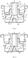
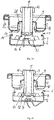
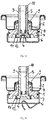
- the figures 1a to 3b show a valve for a container for dispensing pressurized fluid, preferably foam, in particular one component or two component polyurethane foam.
- the valve comprises a housing 1 which is mounted on a valve cup 2.
- a hollow stem 3 is provided which has at least one lateral inlet opening 4 at its lower end and an outlet opening 5 at its upper end.
- the stem 3 is displaceable in the passage between a closed position and an open position.
- the housing 1 has a circumferential step-like contour with an outer, lower part 7 and a central, upper part 8. According to the present invention, the valve cup 2 then follows essentially the step-like circumferential contour line of the housing 1 and ends horizontally on the top of the housing 1 close to the stem 3.
- the outer end of the valve cup 2 is bended and thereby designed to be fixed to a container containing the pressurized fluid.
- the valve cup 2 then has a first vertical part 2a extending downwards and ending by a curb over the outer, lower part 7 of the housing.
- first horizontal part 2b extending to the centre of the valve which is essentially parallel to the upper side of the outer, lower part 7 of the housing 1.
- the valve cup 2 is then curbed again and has a second vertical part 2c extending upwards which is essentially parallel to the vertical side of the central, upper part 8 of the housing.
- At the end of this vertical part 2c it is bended again and has a further horizontal part 2d extending to the centre of the valve. This further horizontal part 2d is essentially parallel to the upper side of the central, upper part 8 of the housing 1.
- a sealing 9 is provided which seals at the same time the valve cup 2 against the housing 1 and the stem 3 against the housing 1. This sealing 9 is placed on the top of the central, upper part 8 of the housing 1.
- valve cup 2 is crimped around the housing 1. This crimping step deforms the area 2c and thereby fixes the valve cup 2 on the housing 1 and at the same time the sealing 9 in its position between the housing 1 and the valve cup 2 and the stem 3.
- the stem 3 is pushed by spring means 6, here a metallic spring 6, in the closed position and can be opened against the force of the spring means 6.
- spring means 6, here a metallic spring 6, in the closed position and can be opened against the force of the spring means 6.
- the lower part of the housing 1 situated in the container is provided with a circumferential groove 11 in which the metallic spring 6 is held.
- a top sealing part 10 can be provided around the outlet opening 5 of the stem 3.
- Means for limiting the opening distance of the valve can also be provided.
- Such means which limit the course of the stem to a maximum value can be a specially designed spring which limits the opening distance of the valve and prevents the valve from being deformed.
- valves of the figures 1a/1b , 2a/2b and 3a/3b differ in the way the sealing between the stem 2 and the housing 1 is achieved.
- the stem 3 is provided on its lower end situated in the container with a flange 12 that is pushed by the spring means 6 in the closed position against the housing thereby closing the passageway through the stem 3.
- the flange of the stem 3 abuts in the closed position against a flat part of the housing 1 so that there is a surface contact between the flange 12 of the stem 3 and the housing 1.
- FIG. 2a/2b differs therefrom in that a rib 13 is provided on the housing 1.
- the flat flange 12 of the stem 3 is pushed by the spring means 6 against the rib 13 so that there is an annular contact between the flange 12 of the stem 3 and the housing 1.
- the flange 12 of the stem 3 has a conical shape and it abuts in the closed position against a lipseal 14 provided on the housing 1.
- the sealing surface is smaller and consequently the sealing force per surface unit is higher than for the full surface contact between the flange 12 of the stem 3 and the housing 1.
- the top sealing part 10 which is provided around the outlet opening 5 of the stem 3 is implemented in the stem 3 by two-component injection.
- the soft material of the top sealing part 10 is moulded on the harder material of the stem 3.
Landscapes
- Chemical & Material Sciences (AREA)
- Dispersion Chemistry (AREA)
- Engineering & Computer Science (AREA)
- Mechanical Engineering (AREA)
- Containers And Packaging Bodies Having A Special Means To Remove Contents (AREA)
- Nozzles (AREA)
Claims (8)
- Ventil für einen Behälter zur Abgabe von unter Druck stehendem Fluid, wobei das Ventil ein Gehäuse (1), das auf einem Ventilteller (2) montiert ist, einen hohlen Schaft (3), der in einem Durchgang des Gehäuses (1) vorgesehen ist, wobei der Schaft (3) mindestens eine seitliche Einlassöffnung (4) an seinem unteren Ende und eine Auslassöffnung (5) an seinem oberen Ende aufweist, wobei der Schaft (3) zwischen einer geschlossenen Position und einer offenen Position verschiebbar ist und Federmittel (6) umfasst, mittels derer der Schaft (3) in die geschlossene Position gedrückt wird, wobei das Gehäuse (1) eine umlaufende stufenartige Kontur mit einem äußeren, unteren Teil (7) und einem mittleren, oberen Teil (8) aufweist, wobei der Ventilteller (2) im Wesentlichen der stufenförmigen Konturlinie des Gehäuses (1) folgt und an der Oberseite des Gehäuses (1) nahe dem Schaft (3) horizontal endet und wobei an der Oberseite des Gehäuses (1) zwischen dem Gehäuse (1) und dem Ventilteller (2) eine Dichtung (9) vorgesehen ist, die gleichzeitig den Ventilteller (2) gegen das Gehäuse (1) und den Schaft (3) gegen das Gehäuse (1) abdichtet, dadurch gekennzeichnet, dass der untere Teil des Gehäuses (1), der sich in dem Behälter befindet, mit einer umlaufenden Nut (11) versehen ist, in der das Federmittel (6), vorzugsweise ein Federelement (6), vorzugsweise ein metallisches Federelement (6), gehalten wird, das den Schaft (3) in die geschlossene Position drückt.
- Ventil nach Anspruch 1, dadurch gekennzeichnet, dass der Ventilteller (2) um das Gehäuse (1) gepresst ist.
- Ventil nach einem der Ansprüche 1 bis 2, dadurch gekennzeichnet, dass der Schaft (3) an seinem unteren, im Behälter befindlichen Ende mit einem Flansch (12) versehen ist, der in der geschlossenen Stellung am Gehäuse (1) anliegt und dadurch den Durchgang durch den Schaft (3) verschließt.
- Ventil nach Anspruch 3, dadurch gekennzeichnet, dass der Flansch (12) des Schafts (3) in der geschlossenen Stellung an einem flachen Teil des Gehäuses (1) anliegt.
- Ventil nach Anspruch 3, dadurch gekennzeichnet, dass der Flansch (12) des Schafts (3) in der Schließstellung an einer kreisförmigen Rippe (13) am Gehäuse (1) anliegt.
- Ventil nach Anspruch 3, dadurch gekennzeichnet, dass der Flansch (12) des Schafts (3) einen konisch geformten Flansch (12) aufweist, der in der Schließstellung an einer Lippendichtung anliegt, die sich am Gehäuse (1) befindet.
- Ventil nach einem der Ansprüche 1 bis 6, dadurch gekennzeichnet, dass um die Auslassöffnung (5) des Schafts (3) ein oberes Dichtungsteil (10) vorgesehen ist.
- Ventil nach einem der Ansprüche 1 bis 7, dadurch gekennzeichnet, dass Mittel zur Begrenzung des Öffnungsweges des Ventils vorgesehen sind.
Priority Applications (1)
| Application Number | Priority Date | Filing Date | Title |
|---|---|---|---|
| PL18778424T PL3684708T3 (pl) | 2017-09-21 | 2018-09-20 | Zawór do zbiornika, odpowiedni sposób i zastosowanie |
Applications Claiming Priority (2)
| Application Number | Priority Date | Filing Date | Title |
|---|---|---|---|
| BE2017/5671A BE1025177B1 (nl) | 2017-09-21 | 2017-09-21 | Klep voor een houder |
| PCT/EP2018/075519 WO2019057842A1 (en) | 2017-09-21 | 2018-09-20 | VALVE FOR CONTAINER, METHOD AND USE THEREOF |
Publications (2)
| Publication Number | Publication Date |
|---|---|
| EP3684708A1 EP3684708A1 (de) | 2020-07-29 |
| EP3684708B1 true EP3684708B1 (de) | 2022-01-05 |
Family
ID=60781409
Family Applications (1)
| Application Number | Title | Priority Date | Filing Date |
|---|---|---|---|
| EP18778424.4A Active EP3684708B1 (de) | 2017-09-21 | 2018-09-20 | Ventil für einen behälter, entsprechendes verfahren und verwendung |
Country Status (7)
| Country | Link |
|---|---|
| US (1) | US11130623B2 (de) |
| EP (1) | EP3684708B1 (de) |
| CN (1) | CN111132913B (de) |
| BE (1) | BE1025177B1 (de) |
| HU (1) | HUE058082T2 (de) |
| PL (1) | PL3684708T3 (de) |
| WO (1) | WO2019057842A1 (de) |
Families Citing this family (2)
| Publication number | Priority date | Publication date | Assignee | Title |
|---|---|---|---|---|
| BE1027834B1 (nl) * | 2020-05-22 | 2021-07-02 | Altachem | Kogelgewrichtklep |
| TWI856457B (zh) * | 2022-12-19 | 2024-09-21 | 乾唐軒美術工藝股份有限公司 | 壓力容器雙向釋壓閥組及實施該閥組之壓力容器 |
Family Cites Families (58)
| Publication number | Priority date | Publication date | Assignee | Title |
|---|---|---|---|---|
| BE549064A (de) * | 1954-09-20 | |||
| US2869764A (en) * | 1955-01-17 | 1959-01-20 | Pressure Dispensers Inc | Self-closing valve construction for a pressurized container |
| US2889086A (en) * | 1955-05-02 | 1959-06-02 | Pressure Dispensers Inc | Dispensing valve with stem sealing means |
| US2994461A (en) * | 1957-07-02 | 1961-08-01 | Michel David Daniel | Dispensing apparatus |
| US3249261A (en) * | 1963-08-30 | 1966-05-03 | Avoset Company | Post-use foaming prevention means for aerosol foam type containers |
| AU426511B2 (en) * | 1967-11-06 | 1972-07-26 | Samuel Taylor Pty. Limited | Improvements in or relating to aerosol valves |
| US3593895A (en) * | 1968-10-30 | 1971-07-20 | Scovill Manufacturing Co | Non-clogging aerosol valve |
| US3583608A (en) * | 1969-05-15 | 1971-06-08 | Scovill Manufacturing Co | Aerosol valve with metering passage |
| US3612362A (en) * | 1969-06-12 | 1971-10-12 | Geigy Chem Corp | Aerosol dispenser with plastic propellant cartridge |
| US3612361A (en) * | 1969-10-20 | 1971-10-12 | Seaquist Valve Co | Self-cleaning valve |
| US3620422A (en) * | 1969-12-05 | 1971-11-16 | Gillette Co | Aerosol valve with flexible housing |
| US3633798A (en) * | 1969-12-22 | 1972-01-11 | Gillette Co | Aerosol valve |
| US3637114A (en) * | 1970-09-03 | 1972-01-25 | Philip Meshberg | Device for codispensing two materials |
| US3653558A (en) * | 1970-10-15 | 1972-04-04 | Scovill Manufacturing Co | Aerosol valve having selectable spray rate |
| US3674186A (en) * | 1970-11-23 | 1972-07-04 | Pittway Corp | Co-dispensing valve |
| US3791561A (en) * | 1971-07-08 | 1974-02-12 | Seaquist Valve Co | Pressure relief system for an aerosol dispenser |
| US3774810A (en) * | 1971-08-12 | 1973-11-27 | Diamond Int Corp | Liquid product dispenser |
| US3756476A (en) * | 1972-05-16 | 1973-09-04 | Colgate Palmolive Co | Pressurized dispenser having diaphragm enclosed skirted piston |
| US3813013A (en) * | 1972-06-27 | 1974-05-28 | Risdon Mfg Co | Aerosol metering valve |
| DE2236068A1 (de) * | 1972-07-22 | 1974-02-14 | Praezisions Ventil Gmbh | Ventil fuer druckgaspackungen |
| GB1516136A (en) * | 1975-06-07 | 1978-06-28 | Aerosol Inventions Dev | Valves for pressurised dispensers |
| US4139128A (en) * | 1976-06-10 | 1979-02-13 | Seaquist Valve Co., A Division Of Pittway Corporation | Variable spray valve assembly |
| US4258904A (en) * | 1978-01-09 | 1981-03-31 | Application Des Gaz | Valves for closing containers under fluid pressure |
| FR2416853A1 (fr) * | 1978-02-13 | 1979-09-07 | Aerosol Inventions Dev | Valve a prise de gaz additionnel |
| US4418847A (en) * | 1982-07-02 | 1983-12-06 | Beard Walter C | Tip sealing tilt valve structure for viscous flow liquids |
| GB8330851D0 (en) * | 1983-11-18 | 1983-12-29 | Fisons Plc | Device |
| JPH0794268B2 (ja) * | 1985-10-16 | 1995-10-11 | ロセプ−ル−ソル ホ−ルデイングス リミテツド | エアロゾル用弁作動装置 |
| GB8628472D0 (en) * | 1986-11-28 | 1987-01-07 | Glaxo Group Ltd | Valve assembly |
| US5605258A (en) * | 1986-12-03 | 1997-02-25 | Abplanalp; Robert H. | Two-piece aerosol valve for vertical or tilt action |
| GB8720978D0 (en) * | 1987-09-07 | 1987-10-14 | Bespak Plc | Collapsible chamber metering valve |
| GB8825632D0 (en) * | 1988-11-02 | 1988-12-07 | Bespak Plc | Dispensing apparatus for pressurised dispensing containers |
| US5397059A (en) * | 1992-03-20 | 1995-03-14 | L'oreal | Dispenser equipped with a liquid pump and a pressurized gas/liquid nozzle |
| GB9414236D0 (en) * | 1994-07-14 | 1994-08-31 | V A R I S P A | Aerosol metering valves |
| DE4426730C2 (de) * | 1994-07-28 | 2002-09-26 | Ehrensperger C Ag | Ventileinsatz für unter Druck stehende Fluidbehälter |
| DE4443287C2 (de) * | 1994-12-06 | 2001-08-09 | Amv Autom Montage Vertrieb Fa | Ventilanordnung für einen Behälter zur Abgabe von unter Druck stehender Flüssigkeit oder Schaum |
| GB2311982B (en) * | 1996-04-09 | 2000-03-08 | Bespak Plc | Improvements in or relating to valves for dispensers |
| GB2316673B (en) * | 1996-09-03 | 1999-12-29 | Bespak Plc | Metering valve |
| DE19710541A1 (de) * | 1997-03-14 | 1998-09-17 | Ehrensperger C Ag | Als Ventileinsatz für unter Druck stehende Fluidbehälter dienende Vorrichtung |
| GB2329939A (en) * | 1997-06-26 | 1999-04-07 | Glaxo Group Ltd | Self-lubricating valve stem for aerosol containers |
| US5906046A (en) * | 1997-07-31 | 1999-05-25 | Precision Valve Corporation | Aerosol tilt valve and method of forming same |
| DE19937283A1 (de) * | 1999-08-06 | 2001-02-15 | Hilti Ag | Ventilanordnung zur Abgabe von in Behältnissen unter Druck gelagerten fluiden Medien |
| GB2360272B (en) * | 2000-03-07 | 2002-02-13 | Bespak Plc | Improvements in or relating to valves for dispensers |
| DE20005484U1 (de) * | 2000-03-23 | 2000-07-06 | Aerosol Technik Lindal Gmbh, 23843 Bad Oldesloe | Spenderpackung |
| EP1485309B1 (de) * | 2002-01-24 | 2009-11-18 | Rathor Ag | Ventil |
| US7264142B2 (en) * | 2004-01-27 | 2007-09-04 | Medical Instill Technologies, Inc. | Dispenser having variable-volume storage chamber and depressible one-way valve assembly for dispensing creams and other substances |
| AU2007100166A4 (en) * | 2007-03-02 | 2007-03-29 | Magnum Manufacturing Pty Ltd | Valve for aerosol containers |
| US8905273B2 (en) * | 2007-07-05 | 2014-12-09 | Altachem Holding Nv | Aerosol valve |
| DE102008019224B4 (de) | 2008-04-17 | 2010-09-02 | Lindal Dispenser Gmbh | Ventilanordnung für einen unter Druck stehenden Fluidbehälter |
| DE102008051888B4 (de) | 2008-10-16 | 2011-02-03 | C. Ehrensperger Ag | Ventil für einen Behälter zur Abgabe von unter Druck stehendem Fluid |
| DE102008051889B4 (de) * | 2008-10-16 | 2014-03-13 | Trumpf Werkzeugmaschinen Gmbh + Co. Kg | Werkzeug zur Bearbeitung eines Werkstückes, insbesondere für die Blechbearbeitung, sowie Auswerfereinrichtung |
| US8800824B2 (en) * | 2012-02-29 | 2014-08-12 | Alfonso M. Gañan-Calvo | Sequential delivery valve apparatus and methods |
| CN203211741U (zh) * | 2013-01-23 | 2013-09-25 | 中山市美捷时包装制品有限公司 | 连续雌阀 |
| WO2014152696A1 (en) * | 2013-03-15 | 2014-09-25 | Precision Valve Corporation | Aerosol valve with defined flow paths |
| GB201402358D0 (en) * | 2013-06-14 | 2014-03-26 | Hawthorne Gary | Salfordlock |
| CN203638423U (zh) * | 2013-08-27 | 2014-06-11 | 中山市美捷时包装制品有限公司 | 一种袋式耐腐蚀型雌阀 |
| GB2526821B (en) * | 2014-06-03 | 2016-04-27 | The Salford Valve Company | Valve assembly |
| KR101665540B1 (ko) * | 2016-03-28 | 2016-10-14 | 오제이씨(주) | 가스용기의 안전밸브 |
| DE102018108846A1 (de) * | 2018-04-13 | 2019-10-17 | C. Ehrensperger Ag | Adapter für Produktspender und Produktspender |
-
2017
- 2017-09-21 BE BE2017/5671A patent/BE1025177B1/nl not_active IP Right Cessation
-
2018
- 2018-09-20 HU HUE18778424A patent/HUE058082T2/hu unknown
- 2018-09-20 CN CN201880060699.7A patent/CN111132913B/zh active Active
- 2018-09-20 US US16/649,431 patent/US11130623B2/en not_active Expired - Fee Related
- 2018-09-20 EP EP18778424.4A patent/EP3684708B1/de active Active
- 2018-09-20 PL PL18778424T patent/PL3684708T3/pl unknown
- 2018-09-20 WO PCT/EP2018/075519 patent/WO2019057842A1/en not_active Ceased
Also Published As
| Publication number | Publication date |
|---|---|
| US11130623B2 (en) | 2021-09-28 |
| CN111132913B (zh) | 2022-02-11 |
| CN111132913A (zh) | 2020-05-08 |
| WO2019057842A1 (en) | 2019-03-28 |
| HUE058082T2 (hu) | 2022-06-28 |
| BE1025177B1 (nl) | 2018-11-29 |
| EP3684708A1 (de) | 2020-07-29 |
| PL3684708T3 (pl) | 2022-05-30 |
| US20200239222A1 (en) | 2020-07-30 |
| BE1025177A1 (nl) | 2018-11-22 |
Similar Documents
| Publication | Publication Date | Title |
|---|---|---|
| RU2491217C2 (ru) | Установочный узел клапана с элементом, предотвращающим смещение щелей | |
| KR101881612B1 (ko) | 압력구동식 분배 컨테이너를 위한 탄성 폐쇄장치 | |
| EP2771252B1 (de) | Flüssigkeitsausgabeanordnung | |
| EP2467315B1 (de) | Ventil mit Sicherheitsvorsprung | |
| EP3683169A1 (de) | Verfahren zur montage eines ausgabesystems zur dosierung eines flüssigen mediums | |
| CN110139809B (zh) | 包括塑料瓶的加压分配系统 | |
| CN106458382A (zh) | 具有自闭阀的水瓶 | |
| EP3102533B1 (de) | Getränkeausgabeanordnung und zapfhahn | |
| EP3684708B1 (de) | Ventil für einen behälter, entsprechendes verfahren und verwendung | |
| WO2016014099A1 (en) | Bottle valve insert | |
| JP3242093B2 (ja) | 加圧された液体を放出するためのバルブ、このバルブを備えた容器およびその容器の製造方法 | |
| EP3110712B1 (de) | Aerosolbehälter und details davon | |
| JP2000007007A (ja) | バルブおよびこのバルブを備えた収容吐出アセンブリ | |
| JP6990398B2 (ja) | 注出弁付き容器 | |
| EP4153507B1 (de) | Kugelgelenkventil | |
| WO2012054967A1 (en) | Pressure release apparatus for a pressurised container | |
| US20100163436A1 (en) | Insert for beverage container | |
| JP7122034B1 (ja) | 連結システム及び逆止弁 | |
| JP7731911B2 (ja) | 飲料容器用バルブ | |
| KR20150078224A (ko) | 박막 튜브형 공기 밸브 및 이를 적용한 디스팬서용 병마개 | |
| US10099843B2 (en) | Click-in valve |
Legal Events
| Date | Code | Title | Description |
|---|---|---|---|
| STAA | Information on the status of an ep patent application or granted ep patent |
Free format text: STATUS: UNKNOWN |
|
| STAA | Information on the status of an ep patent application or granted ep patent |
Free format text: STATUS: THE INTERNATIONAL PUBLICATION HAS BEEN MADE |
|
| PUAI | Public reference made under article 153(3) epc to a published international application that has entered the european phase |
Free format text: ORIGINAL CODE: 0009012 |
|
| STAA | Information on the status of an ep patent application or granted ep patent |
Free format text: STATUS: REQUEST FOR EXAMINATION WAS MADE |
|
| 17P | Request for examination filed |
Effective date: 20200317 |
|
| AK | Designated contracting states |
Kind code of ref document: A1 Designated state(s): AL AT BE BG CH CY CZ DE DK EE ES FI FR GB GR HR HU IE IS IT LI LT LU LV MC MK MT NL NO PL PT RO RS SE SI SK SM TR |
|
| AX | Request for extension of the european patent |
Extension state: BA ME |
|
| DAV | Request for validation of the european patent (deleted) | ||
| DAX | Request for extension of the european patent (deleted) | ||
| GRAP | Despatch of communication of intention to grant a patent |
Free format text: ORIGINAL CODE: EPIDOSNIGR1 |
|
| STAA | Information on the status of an ep patent application or granted ep patent |
Free format text: STATUS: GRANT OF PATENT IS INTENDED |
|
| INTG | Intention to grant announced |
Effective date: 20210823 |
|
| GRAS | Grant fee paid |
Free format text: ORIGINAL CODE: EPIDOSNIGR3 |
|
| GRAA | (expected) grant |
Free format text: ORIGINAL CODE: 0009210 |
|
| STAA | Information on the status of an ep patent application or granted ep patent |
Free format text: STATUS: THE PATENT HAS BEEN GRANTED |
|
| AK | Designated contracting states |
Kind code of ref document: B1 Designated state(s): AL AT BE BG CH CY CZ DE DK EE ES FI FR GB GR HR HU IE IS IT LI LT LU LV MC MK MT NL NO PL PT RO RS SE SI SK SM TR |
|
| REG | Reference to a national code |
Ref country code: GB Ref legal event code: FG4D |
|
| REG | Reference to a national code |
Ref country code: CH Ref legal event code: EP |
|
| REG | Reference to a national code |
Ref country code: AT Ref legal event code: REF Ref document number: 1460353 Country of ref document: AT Kind code of ref document: T Effective date: 20220115 |
|
| REG | Reference to a national code |
Ref country code: DE Ref legal event code: R096 Ref document number: 602018029185 Country of ref document: DE |
|
| REG | Reference to a national code |
Ref country code: IE Ref legal event code: FG4D |
|
| REG | Reference to a national code |
Ref country code: RO Ref legal event code: EPE |
|
| REG | Reference to a national code |
Ref country code: NL Ref legal event code: FP |
|
| REG | Reference to a national code |
Ref country code: LT Ref legal event code: MG9D |
|
| REG | Reference to a national code |
Ref country code: EE Ref legal event code: FG4A Ref document number: E022120 Country of ref document: EE Effective date: 20220331 |
|
| REG | Reference to a national code |
Ref country code: AT Ref legal event code: MK05 Ref document number: 1460353 Country of ref document: AT Kind code of ref document: T Effective date: 20220105 |
|
| REG | Reference to a national code |
Ref country code: HU Ref legal event code: AG4A Ref document number: E058082 Country of ref document: HU |
|
| PG25 | Lapsed in a contracting state [announced via postgrant information from national office to epo] |
Ref country code: SE Free format text: LAPSE BECAUSE OF FAILURE TO SUBMIT A TRANSLATION OF THE DESCRIPTION OR TO PAY THE FEE WITHIN THE PRESCRIBED TIME-LIMIT Effective date: 20220105 Ref country code: RS Free format text: LAPSE BECAUSE OF FAILURE TO SUBMIT A TRANSLATION OF THE DESCRIPTION OR TO PAY THE FEE WITHIN THE PRESCRIBED TIME-LIMIT Effective date: 20220105 Ref country code: PT Free format text: LAPSE BECAUSE OF FAILURE TO SUBMIT A TRANSLATION OF THE DESCRIPTION OR TO PAY THE FEE WITHIN THE PRESCRIBED TIME-LIMIT Effective date: 20220505 Ref country code: NO Free format text: LAPSE BECAUSE OF FAILURE TO SUBMIT A TRANSLATION OF THE DESCRIPTION OR TO PAY THE FEE WITHIN THE PRESCRIBED TIME-LIMIT Effective date: 20220405 Ref country code: LT Free format text: LAPSE BECAUSE OF FAILURE TO SUBMIT A TRANSLATION OF THE DESCRIPTION OR TO PAY THE FEE WITHIN THE PRESCRIBED TIME-LIMIT Effective date: 20220105 Ref country code: HR Free format text: LAPSE BECAUSE OF FAILURE TO SUBMIT A TRANSLATION OF THE DESCRIPTION OR TO PAY THE FEE WITHIN THE PRESCRIBED TIME-LIMIT Effective date: 20220105 Ref country code: ES Free format text: LAPSE BECAUSE OF FAILURE TO SUBMIT A TRANSLATION OF THE DESCRIPTION OR TO PAY THE FEE WITHIN THE PRESCRIBED TIME-LIMIT Effective date: 20220105 Ref country code: BG Free format text: LAPSE BECAUSE OF FAILURE TO SUBMIT A TRANSLATION OF THE DESCRIPTION OR TO PAY THE FEE WITHIN THE PRESCRIBED TIME-LIMIT Effective date: 20220405 |
|
| PG25 | Lapsed in a contracting state [announced via postgrant information from national office to epo] |
Ref country code: LV Free format text: LAPSE BECAUSE OF FAILURE TO SUBMIT A TRANSLATION OF THE DESCRIPTION OR TO PAY THE FEE WITHIN THE PRESCRIBED TIME-LIMIT Effective date: 20220105 Ref country code: GR Free format text: LAPSE BECAUSE OF FAILURE TO SUBMIT A TRANSLATION OF THE DESCRIPTION OR TO PAY THE FEE WITHIN THE PRESCRIBED TIME-LIMIT Effective date: 20220406 Ref country code: FI Free format text: LAPSE BECAUSE OF FAILURE TO SUBMIT A TRANSLATION OF THE DESCRIPTION OR TO PAY THE FEE WITHIN THE PRESCRIBED TIME-LIMIT Effective date: 20220105 Ref country code: AT Free format text: LAPSE BECAUSE OF FAILURE TO SUBMIT A TRANSLATION OF THE DESCRIPTION OR TO PAY THE FEE WITHIN THE PRESCRIBED TIME-LIMIT Effective date: 20220105 |
|
| PG25 | Lapsed in a contracting state [announced via postgrant information from national office to epo] |
Ref country code: IS Free format text: LAPSE BECAUSE OF FAILURE TO SUBMIT A TRANSLATION OF THE DESCRIPTION OR TO PAY THE FEE WITHIN THE PRESCRIBED TIME-LIMIT Effective date: 20220505 |
|
| REG | Reference to a national code |
Ref country code: DE Ref legal event code: R097 Ref document number: 602018029185 Country of ref document: DE |
|
| PG25 | Lapsed in a contracting state [announced via postgrant information from national office to epo] |
Ref country code: SM Free format text: LAPSE BECAUSE OF FAILURE TO SUBMIT A TRANSLATION OF THE DESCRIPTION OR TO PAY THE FEE WITHIN THE PRESCRIBED TIME-LIMIT Effective date: 20220105 Ref country code: SK Free format text: LAPSE BECAUSE OF FAILURE TO SUBMIT A TRANSLATION OF THE DESCRIPTION OR TO PAY THE FEE WITHIN THE PRESCRIBED TIME-LIMIT Effective date: 20220105 Ref country code: DK Free format text: LAPSE BECAUSE OF FAILURE TO SUBMIT A TRANSLATION OF THE DESCRIPTION OR TO PAY THE FEE WITHIN THE PRESCRIBED TIME-LIMIT Effective date: 20220105 Ref country code: CZ Free format text: LAPSE BECAUSE OF FAILURE TO SUBMIT A TRANSLATION OF THE DESCRIPTION OR TO PAY THE FEE WITHIN THE PRESCRIBED TIME-LIMIT Effective date: 20220105 |
|
| PGFP | Annual fee paid to national office [announced via postgrant information from national office to epo] |
Ref country code: TR Payment date: 20220919 Year of fee payment: 5 Ref country code: NL Payment date: 20220922 Year of fee payment: 5 Ref country code: EE Payment date: 20220927 Year of fee payment: 5 |
|
| PLBE | No opposition filed within time limit |
Free format text: ORIGINAL CODE: 0009261 |
|
| STAA | Information on the status of an ep patent application or granted ep patent |
Free format text: STATUS: NO OPPOSITION FILED WITHIN TIME LIMIT |
|
| PG25 | Lapsed in a contracting state [announced via postgrant information from national office to epo] |
Ref country code: AL Free format text: LAPSE BECAUSE OF FAILURE TO SUBMIT A TRANSLATION OF THE DESCRIPTION OR TO PAY THE FEE WITHIN THE PRESCRIBED TIME-LIMIT Effective date: 20220105 |
|
| PGFP | Annual fee paid to national office [announced via postgrant information from national office to epo] |
Ref country code: PL Payment date: 20220914 Year of fee payment: 5 |
|
| 26N | No opposition filed |
Effective date: 20221006 |
|
| PG25 | Lapsed in a contracting state [announced via postgrant information from national office to epo] |
Ref country code: SI Free format text: LAPSE BECAUSE OF FAILURE TO SUBMIT A TRANSLATION OF THE DESCRIPTION OR TO PAY THE FEE WITHIN THE PRESCRIBED TIME-LIMIT Effective date: 20220105 |
|
| PG25 | Lapsed in a contracting state [announced via postgrant information from national office to epo] |
Ref country code: RO Free format text: LAPSE BECAUSE OF NON-PAYMENT OF DUE FEES Effective date: 20220105 Ref country code: MC Free format text: LAPSE BECAUSE OF FAILURE TO SUBMIT A TRANSLATION OF THE DESCRIPTION OR TO PAY THE FEE WITHIN THE PRESCRIBED TIME-LIMIT Effective date: 20220105 |
|
| REG | Reference to a national code |
Ref country code: CH Ref legal event code: PL |
|
| GBPC | Gb: european patent ceased through non-payment of renewal fee |
Effective date: 20220920 |
|
| PG25 | Lapsed in a contracting state [announced via postgrant information from national office to epo] |
Ref country code: LU Free format text: LAPSE BECAUSE OF NON-PAYMENT OF DUE FEES Effective date: 20220920 |
|
| PG25 | Lapsed in a contracting state [announced via postgrant information from national office to epo] |
Ref country code: LI Free format text: LAPSE BECAUSE OF NON-PAYMENT OF DUE FEES Effective date: 20220930 Ref country code: IT Free format text: LAPSE BECAUSE OF FAILURE TO SUBMIT A TRANSLATION OF THE DESCRIPTION OR TO PAY THE FEE WITHIN THE PRESCRIBED TIME-LIMIT Effective date: 20220105 Ref country code: IE Free format text: LAPSE BECAUSE OF NON-PAYMENT OF DUE FEES Effective date: 20220920 Ref country code: FR Free format text: LAPSE BECAUSE OF NON-PAYMENT OF DUE FEES Effective date: 20220930 Ref country code: CH Free format text: LAPSE BECAUSE OF NON-PAYMENT OF DUE FEES Effective date: 20220930 |
|
| PG25 | Lapsed in a contracting state [announced via postgrant information from national office to epo] |
Ref country code: GB Free format text: LAPSE BECAUSE OF NON-PAYMENT OF DUE FEES Effective date: 20220920 |
|
| REG | Reference to a national code |
Ref country code: EE Ref legal event code: MM4A Ref document number: E022120 Country of ref document: EE Effective date: 20230930 |
|
| PG25 | Lapsed in a contracting state [announced via postgrant information from national office to epo] |
Ref country code: CY Free format text: LAPSE BECAUSE OF FAILURE TO SUBMIT A TRANSLATION OF THE DESCRIPTION OR TO PAY THE FEE WITHIN THE PRESCRIBED TIME-LIMIT Effective date: 20220105 |
|
| REG | Reference to a national code |
Ref country code: NL Ref legal event code: MM Effective date: 20231001 |
|
| PG25 | Lapsed in a contracting state [announced via postgrant information from national office to epo] |
Ref country code: MK Free format text: LAPSE BECAUSE OF FAILURE TO SUBMIT A TRANSLATION OF THE DESCRIPTION OR TO PAY THE FEE WITHIN THE PRESCRIBED TIME-LIMIT Effective date: 20220105 |
|
| PG25 | Lapsed in a contracting state [announced via postgrant information from national office to epo] |
Ref country code: NL Free format text: LAPSE BECAUSE OF NON-PAYMENT OF DUE FEES Effective date: 20231001 |
|
| PG25 | Lapsed in a contracting state [announced via postgrant information from national office to epo] |
Ref country code: NL Free format text: LAPSE BECAUSE OF NON-PAYMENT OF DUE FEES Effective date: 20231001 |
|
| PG25 | Lapsed in a contracting state [announced via postgrant information from national office to epo] |
Ref country code: EE Free format text: LAPSE BECAUSE OF NON-PAYMENT OF DUE FEES Effective date: 20230930 |
|
| PG25 | Lapsed in a contracting state [announced via postgrant information from national office to epo] |
Ref country code: MT Free format text: LAPSE BECAUSE OF FAILURE TO SUBMIT A TRANSLATION OF THE DESCRIPTION OR TO PAY THE FEE WITHIN THE PRESCRIBED TIME-LIMIT Effective date: 20220105 |
|
| PG25 | Lapsed in a contracting state [announced via postgrant information from national office to epo] |
Ref country code: PL Free format text: LAPSE BECAUSE OF NON-PAYMENT OF DUE FEES Effective date: 20230920 |
|
| PG25 | Lapsed in a contracting state [announced via postgrant information from national office to epo] |
Ref country code: PL Free format text: LAPSE BECAUSE OF NON-PAYMENT OF DUE FEES Effective date: 20230920 |
|
| PGFP | Annual fee paid to national office [announced via postgrant information from national office to epo] |
Ref country code: DE Payment date: 20250919 Year of fee payment: 8 |
|
| PGFP | Annual fee paid to national office [announced via postgrant information from national office to epo] |
Ref country code: HU Payment date: 20250911 Year of fee payment: 8 Ref country code: BE Payment date: 20250919 Year of fee payment: 8 |