EP3685036B1 - Éolienne et procédé permettant de faire fonctionner une éolienne - Google Patents
Éolienne et procédé permettant de faire fonctionner une éolienne Download PDFInfo
- Publication number
- EP3685036B1 EP3685036B1 EP18762289.9A EP18762289A EP3685036B1 EP 3685036 B1 EP3685036 B1 EP 3685036B1 EP 18762289 A EP18762289 A EP 18762289A EP 3685036 B1 EP3685036 B1 EP 3685036B1
- Authority
- EP
- European Patent Office
- Prior art keywords
- load
- loading
- generator
- wind
- variable
- Prior art date
- Legal status (The legal status is an assumption and is not a legal conclusion. Google has not performed a legal analysis and makes no representation as to the accuracy of the status listed.)
- Active
Links
Images


Classifications
-
- F—MECHANICAL ENGINEERING; LIGHTING; HEATING; WEAPONS; BLASTING
- F03—MACHINES OR ENGINES FOR LIQUIDS; WIND, SPRING, OR WEIGHT MOTORS; PRODUCING MECHANICAL POWER OR A REACTIVE PROPULSIVE THRUST, NOT OTHERWISE PROVIDED FOR
- F03D—WIND MOTORS
- F03D7/00—Controlling wind motors
- F03D7/02—Controlling wind motors the wind motors having rotation axis substantially parallel to the air flow entering the rotor
- F03D7/04—Automatic control; Regulation
- F03D7/042—Automatic control; Regulation by means of an electrical or electronic controller
- F03D7/043—Automatic control; Regulation by means of an electrical or electronic controller characterised by the type of control logic
- F03D7/045—Automatic control; Regulation by means of an electrical or electronic controller characterised by the type of control logic with model-based controls
-
- F—MECHANICAL ENGINEERING; LIGHTING; HEATING; WEAPONS; BLASTING
- F03—MACHINES OR ENGINES FOR LIQUIDS; WIND, SPRING, OR WEIGHT MOTORS; PRODUCING MECHANICAL POWER OR A REACTIVE PROPULSIVE THRUST, NOT OTHERWISE PROVIDED FOR
- F03D—WIND MOTORS
- F03D7/00—Controlling wind motors
- F03D7/02—Controlling wind motors the wind motors having rotation axis substantially parallel to the air flow entering the rotor
- F03D7/028—Controlling wind motors the wind motors having rotation axis substantially parallel to the air flow entering the rotor controlling wind motor output power
- F03D7/0292—Controlling wind motors the wind motors having rotation axis substantially parallel to the air flow entering the rotor controlling wind motor output power to reduce fatigue
-
- F—MECHANICAL ENGINEERING; LIGHTING; HEATING; WEAPONS; BLASTING
- F03—MACHINES OR ENGINES FOR LIQUIDS; WIND, SPRING, OR WEIGHT MOTORS; PRODUCING MECHANICAL POWER OR A REACTIVE PROPULSIVE THRUST, NOT OTHERWISE PROVIDED FOR
- F03D—WIND MOTORS
- F03D7/00—Controlling wind motors
- F03D7/02—Controlling wind motors the wind motors having rotation axis substantially parallel to the air flow entering the rotor
- F03D7/022—Adjusting aerodynamic properties of the blades
- F03D7/0224—Adjusting blade pitch
-
- F—MECHANICAL ENGINEERING; LIGHTING; HEATING; WEAPONS; BLASTING
- F03—MACHINES OR ENGINES FOR LIQUIDS; WIND, SPRING, OR WEIGHT MOTORS; PRODUCING MECHANICAL POWER OR A REACTIVE PROPULSIVE THRUST, NOT OTHERWISE PROVIDED FOR
- F03D—WIND MOTORS
- F03D7/00—Controlling wind motors
- F03D7/02—Controlling wind motors the wind motors having rotation axis substantially parallel to the air flow entering the rotor
- F03D7/028—Controlling wind motors the wind motors having rotation axis substantially parallel to the air flow entering the rotor controlling wind motor output power
- F03D7/0288—Controlling wind motors the wind motors having rotation axis substantially parallel to the air flow entering the rotor controlling wind motor output power in relation to clearance between the blade and the tower, i.e. preventing tower strike
-
- F—MECHANICAL ENGINEERING; LIGHTING; HEATING; WEAPONS; BLASTING
- F03—MACHINES OR ENGINES FOR LIQUIDS; WIND, SPRING, OR WEIGHT MOTORS; PRODUCING MECHANICAL POWER OR A REACTIVE PROPULSIVE THRUST, NOT OTHERWISE PROVIDED FOR
- F03D—WIND MOTORS
- F03D7/00—Controlling wind motors
- F03D7/02—Controlling wind motors the wind motors having rotation axis substantially parallel to the air flow entering the rotor
- F03D7/04—Automatic control; Regulation
- F03D7/042—Automatic control; Regulation by means of an electrical or electronic controller
- F03D7/043—Automatic control; Regulation by means of an electrical or electronic controller characterised by the type of control logic
- F03D7/044—Automatic control; Regulation by means of an electrical or electronic controller characterised by the type of control logic with PID control
-
- F—MECHANICAL ENGINEERING; LIGHTING; HEATING; WEAPONS; BLASTING
- F05—INDEXING SCHEMES RELATING TO ENGINES OR PUMPS IN VARIOUS SUBCLASSES OF CLASSES F01-F04
- F05B—INDEXING SCHEME RELATING TO WIND, SPRING, WEIGHT, INERTIA OR LIKE MOTORS, TO MACHINES OR ENGINES FOR LIQUIDS COVERED BY SUBCLASSES F03B, F03D AND F03G
- F05B2240/00—Components
- F05B2240/20—Rotors
- F05B2240/21—Rotors for wind turbines
- F05B2240/221—Rotors for wind turbines with horizontal axis
-
- F—MECHANICAL ENGINEERING; LIGHTING; HEATING; WEAPONS; BLASTING
- F05—INDEXING SCHEMES RELATING TO ENGINES OR PUMPS IN VARIOUS SUBCLASSES OF CLASSES F01-F04
- F05B—INDEXING SCHEME RELATING TO WIND, SPRING, WEIGHT, INERTIA OR LIKE MOTORS, TO MACHINES OR ENGINES FOR LIQUIDS COVERED BY SUBCLASSES F03B, F03D AND F03G
- F05B2270/00—Control
- F05B2270/10—Purpose of the control system
- F05B2270/101—Purpose of the control system to control rotational speed (n)
-
- F—MECHANICAL ENGINEERING; LIGHTING; HEATING; WEAPONS; BLASTING
- F05—INDEXING SCHEMES RELATING TO ENGINES OR PUMPS IN VARIOUS SUBCLASSES OF CLASSES F01-F04
- F05B—INDEXING SCHEME RELATING TO WIND, SPRING, WEIGHT, INERTIA OR LIKE MOTORS, TO MACHINES OR ENGINES FOR LIQUIDS COVERED BY SUBCLASSES F03B, F03D AND F03G
- F05B2270/00—Control
- F05B2270/10—Purpose of the control system
- F05B2270/109—Purpose of the control system to prolong engine life
- F05B2270/1095—Purpose of the control system to prolong engine life by limiting mechanical stresses
-
- F—MECHANICAL ENGINEERING; LIGHTING; HEATING; WEAPONS; BLASTING
- F05—INDEXING SCHEMES RELATING TO ENGINES OR PUMPS IN VARIOUS SUBCLASSES OF CLASSES F01-F04
- F05B—INDEXING SCHEME RELATING TO WIND, SPRING, WEIGHT, INERTIA OR LIKE MOTORS, TO MACHINES OR ENGINES FOR LIQUIDS COVERED BY SUBCLASSES F03B, F03D AND F03G
- F05B2270/00—Control
- F05B2270/30—Control parameters, e.g. input parameters
- F05B2270/32—Wind speeds
-
- F—MECHANICAL ENGINEERING; LIGHTING; HEATING; WEAPONS; BLASTING
- F05—INDEXING SCHEMES RELATING TO ENGINES OR PUMPS IN VARIOUS SUBCLASSES OF CLASSES F01-F04
- F05B—INDEXING SCHEME RELATING TO WIND, SPRING, WEIGHT, INERTIA OR LIKE MOTORS, TO MACHINES OR ENGINES FOR LIQUIDS COVERED BY SUBCLASSES F03B, F03D AND F03G
- F05B2270/00—Control
- F05B2270/30—Control parameters, e.g. input parameters
- F05B2270/326—Rotor angle
-
- F—MECHANICAL ENGINEERING; LIGHTING; HEATING; WEAPONS; BLASTING
- F05—INDEXING SCHEMES RELATING TO ENGINES OR PUMPS IN VARIOUS SUBCLASSES OF CLASSES F01-F04
- F05B—INDEXING SCHEME RELATING TO WIND, SPRING, WEIGHT, INERTIA OR LIKE MOTORS, TO MACHINES OR ENGINES FOR LIQUIDS COVERED BY SUBCLASSES F03B, F03D AND F03G
- F05B2270/00—Control
- F05B2270/30—Control parameters, e.g. input parameters
- F05B2270/327—Rotor or generator speeds
-
- F—MECHANICAL ENGINEERING; LIGHTING; HEATING; WEAPONS; BLASTING
- F05—INDEXING SCHEMES RELATING TO ENGINES OR PUMPS IN VARIOUS SUBCLASSES OF CLASSES F01-F04
- F05B—INDEXING SCHEME RELATING TO WIND, SPRING, WEIGHT, INERTIA OR LIKE MOTORS, TO MACHINES OR ENGINES FOR LIQUIDS COVERED BY SUBCLASSES F03B, F03D AND F03G
- F05B2270/00—Control
- F05B2270/30—Control parameters, e.g. input parameters
- F05B2270/328—Blade pitch angle
-
- F—MECHANICAL ENGINEERING; LIGHTING; HEATING; WEAPONS; BLASTING
- F05—INDEXING SCHEMES RELATING TO ENGINES OR PUMPS IN VARIOUS SUBCLASSES OF CLASSES F01-F04
- F05B—INDEXING SCHEME RELATING TO WIND, SPRING, WEIGHT, INERTIA OR LIKE MOTORS, TO MACHINES OR ENGINES FOR LIQUIDS COVERED BY SUBCLASSES F03B, F03D AND F03G
- F05B2270/00—Control
- F05B2270/30—Control parameters, e.g. input parameters
- F05B2270/331—Mechanical loads
-
- F—MECHANICAL ENGINEERING; LIGHTING; HEATING; WEAPONS; BLASTING
- F05—INDEXING SCHEMES RELATING TO ENGINES OR PUMPS IN VARIOUS SUBCLASSES OF CLASSES F01-F04
- F05B—INDEXING SCHEME RELATING TO WIND, SPRING, WEIGHT, INERTIA OR LIKE MOTORS, TO MACHINES OR ENGINES FOR LIQUIDS COVERED BY SUBCLASSES F03B, F03D AND F03G
- F05B2270/00—Control
- F05B2270/30—Control parameters, e.g. input parameters
- F05B2270/332—Maximum loads or fatigue criteria
-
- F—MECHANICAL ENGINEERING; LIGHTING; HEATING; WEAPONS; BLASTING
- F05—INDEXING SCHEMES RELATING TO ENGINES OR PUMPS IN VARIOUS SUBCLASSES OF CLASSES F01-F04
- F05B—INDEXING SCHEME RELATING TO WIND, SPRING, WEIGHT, INERTIA OR LIKE MOTORS, TO MACHINES OR ENGINES FOR LIQUIDS COVERED BY SUBCLASSES F03B, F03D AND F03G
- F05B2270/00—Control
- F05B2270/70—Type of control algorithm
- F05B2270/705—Type of control algorithm proportional-integral
-
- Y—GENERAL TAGGING OF NEW TECHNOLOGICAL DEVELOPMENTS; GENERAL TAGGING OF CROSS-SECTIONAL TECHNOLOGIES SPANNING OVER SEVERAL SECTIONS OF THE IPC; TECHNICAL SUBJECTS COVERED BY FORMER USPC CROSS-REFERENCE ART COLLECTIONS [XRACs] AND DIGESTS
- Y02—TECHNOLOGIES OR APPLICATIONS FOR MITIGATION OR ADAPTATION AGAINST CLIMATE CHANGE
- Y02E—REDUCTION OF GREENHOUSE GAS [GHG] EMISSIONS, RELATED TO ENERGY GENERATION, TRANSMISSION OR DISTRIBUTION
- Y02E10/00—Energy generation through renewable energy sources
- Y02E10/70—Wind energy
- Y02E10/72—Wind turbines with rotation axis in wind direction
Definitions
- the present invention relates to a method for operating a wind turbine. Furthermore, the present invention relates to such a wind turbine.
- Wind turbines are well known for generating electrical power from wind. However, if the wind becomes too strong, especially when it reaches storm-like speeds, it may be advisable to shut down the turbine for protection and, in particular, to position it in a plume position so that it offers as little surface area as possible for the storm to attack.
- German Patent and Trademark Office has searched the following prior art in the priority application for the present application: DE 195 32 409 A1 ; DE 10 2006 034 106 A1 ; US 2009/0060740 A1 ; US 2009/0261588 A1 ; WO 2015/086024 A1 and WO 2017/036481 A1
- a force acting on the wind turbine is used to determine the load.
- This can be a direct translational force, or a force acting in a direction of rotation or bending.
- This can also mean that this force acting on the wind turbine is used directly as a load.
- a mechanical load is therefore used as a basis here.
- the force acting on the wind turbine can also be synonymously referred to as a mechanical load acting on the wind turbine. This also includes bending and torsional moments, or combinations thereof.
- Stress operation specifically describes a storm situation or storm operation in which wind speeds equivalent to or exceeding those of a storm occur. Such high wind speeds in particular can place a significant strain on a wind turbine or even endanger it.
- a hub bending moment be recorded and that the hub bending moment be used to determine the load variable or as a load variable.
- a hub bending moment is particularly well suited as a load variable because forces acting on all rotor blades act collectively on the hub and thus significantly influence the hub bending moment.
- the hub bending moment acts directly near the rotor blades, which absorb a large portion of the load on the wind turbine.
- the hub is in close proximity to a rotor bearing and thus to a component that must absorb significant loads on the aerodynamic rotor and can potentially be damaged as a result.
- the hub bending moment can include not only absolute values but also directional values.
- Wind speed can change rapidly not only over time, but also with location, especially with altitude.
- Modern wind turbines have large rotor surfaces, and a wind speed that varies across the rotor surface can lead to uneven loads on the rotor. This, in turn, can be reflected in a hub bending moment.
- the wind turbine can sometimes be subjected to greater stress or endangerment by such uneven loads than by high wind speed alone. It is therefore also possible that wind speed is not a very meaningful criterion for the load on the wind turbine, because a specific wind speed Depending on how and how much it varies, it can lead to very different loads that are not reflected in a value for the wind speed.
- the actual load can be better accounted for. Uneven loading across the rotor field can be taken into account, allowing for more targeted responses. In particular, the speed and/or generator output can be reduced earlier or later, depending on the wind field, based on a specific wind speed value.
- a shaft bending moment, an axle bending moment, and/or a tower head bending moment can also be used to determine the load magnitude or as a load magnitude.
- the explanations and advantages described for the hub bending moment can also be applied to these moments.
- At least one strain measurement is performed on the rotor hub and, additionally or alternatively, at least one rotor blade, in particular at or near the blade root.
- one strain measurement is performed on each rotor blade or at or near each blade root.
- several strain measurements are performed there, in particular two at a time, in order to be able to record different loading directions.
- Such a load measurement can be easily performed using strain measurements, i.e., a measurement using at least one strain gauge, and can often be used for other applications as well. Such a strain measurement can be particularly useful for individual blade adjustment.
- the method is characterized in that the load magnitude is determined using a system-based estimation algorithm based on a measurement representative of the load. Multiple measurements at multiple locations can also be used.
- a measurement is essentially understood to mean a continuous measurement.
- a continuous measurement also includes a quasi-continuous measurement, for example, in which measurements are taken discretely at a high sampling rate.
- strain measurements at the rotor hub and, additionally or alternatively, at the blade root of the rotor blades or in the area of the blade root are used.
- One location in the area of the blade root is particularly on a blade adapter, via which the respective rotor blade is attached to the hub.
- Such a systems-based estimation algorithm can be designed specifically as a calculation rule that establishes a relationship between the respective measurement and the load quantity to be determined.
- strain gauges can be used to measure loads at the blade roots.
- the systems-based estimation algorithm then uses this data to determine the bending moment as a load quantity.
- the calculation algorithm which in this example can serve as the estimation algorithm, is based on a relationship between the respective loads at the blade roots and a resulting bending moment, for example, the hub bending moment.
- Such relationships can be recorded, for example, through representative measurements when input and output variables are measured in a test setup. In this case, the measurements at the blade roots are used as input variables and the resulting hub bending moment is used as the output variable. From this, a system model for this relationship can be created, for example, using known system identification methods. It is also possible to determine such relationships through load simulations. Such load simulations are based on good models of the affected elements of the wind turbine. For example, such models can be determined using finite element methods. A relationship can be recorded and taken into account for each rotor blade. In this example, the load on each blade root (usually three rotor blades and therefore three blade roots can be assumed) results in a partial hub bending moment in terms of magnitude and direction.
- This partial hub bending moment can, for example, be used as a corresponding A vector, namely a force magnitude vector, can be considered or represented.
- These three partial hub bending moments, if three rotor blades are present, can then be vectorially added to form a total hub bending moment.
- matrix multiplication can also be performed to calculate the hub moment from the blade root bending moment. This can be derived from a force equilibrium.
- a weight force depending on the position of the rotor blade, also affects the blade load absorbed at the blade root.
- a weight load can be included in the relationship between the respective load at the blade root and the resulting partial bending moment, taking the blade position into account. For example, if a blade is positioned vertically upwards, i.e. in the so-called 12 o'clock position, and - as an illustrative example - no wind acts on the rotor blade, this could mean that no load at the blade root is recorded by strain gauges.
- this weight alone leads to a hub bending moment, and this is precisely what can be taken into account.
- the strain gauges mentioned can also take such weight forces into account.
- the system-engineering estimation algorithm can be implemented as a state observer.
- the representative measurements, or at least one representative measurement, can be input to this state observer.
- the state observer can then contain a model that, for example, has a speed as an output variable, which results, among other things, from the loads.
- the model behaves like the wind turbine.
- an observation error can be formed and fed back to the observer's adjustment. If, for example, a speed is regulated by adjusting the blade angle, the signal for adjusting the blade angle can form another input variable, which can also be fed into the model. Or, to give another example, the pitch signal may be the only input.
- system-technical estimation algorithm or the state observer can be implemented as a Kalman filter.
- the load limit be set as a function of a load value recorded as a base load during normal operation at prevailing nominal wind speeds.
- a load is therefore recorded during normal operation at prevailing nominal wind speeds, which in this respect can also be referred to synonymously as nominal operation.
- Such a load can be recorded in advance in simulations or during ongoing operation.
- the load limit can then be set to a higher value, in particular to twice the value.
- preliminary system-related investigations can also determine how much higher the load limit is compared to the base load determined during nominal operation.
- the speed and, additionally or alternatively, the generator power are reduced depending on the detected load.
- the determined load value thus forms an input variable for reducing the speed or generator power.
- a controller can therefore be provided that is designed so that the load does not exceed the load limit. This can mean that the load can also be well below the load limit.
- a safety margin can be proposed, which can be achieved by using a lower value than the load limit as the target value instead of the load limit, for example, a value ten percent lower.
- the control will generally attempt to increase the speed and generator power accordingly even if the load variable has not yet reached the load limit.
- the rotational speed and the generator power are reduced in such a way that the load does not exceed the load limit value and, in addition, the rotor blades are each adjusted in their blade angle in the direction out of the wind, and, in addition, the generator torque does not exceed a nominal generator torque and, in addition, the generator torque is reduced with increasing wind speed.
- the speed is reduced, which leads to a reduction in load.
- the angle of attack on the rotor blades is also reduced, which also leads to a reduction in load.
- the generator torque is designed to not exceed the rated generator torque, thus avoiding corresponding electrical overload and also preventing excessive mechanical stress due to the torque.
- the generator torque be reduced with increasing wind speed, which could lead to an increase in speed if the rotor blades are not sufficiently turned out of the wind.
- a speed reduction is also proposed, the rotor blades are turned so far out of the wind that, despite the reduction in generator torque, a reduction in speed results.
- the generator torque is reduced and the speed is reduced, the generator power is also reduced.
- the wind speed can be determined from the known blade angle, the set generator torque, and the resulting rotational speed or a time derivative of the rotational speed. To improve such a wind speed estimate, it is proposed to additionally consider the determined load variable. Such an estimation of wind speed can also be performed using a systems-based estimation algorithm.
- the speed be reduced depending on the determined load variable and that the generator power be reduced depending on a speed-power characteristic curve for load operation.
- the speed-power characteristic curve for load operation differs from a speed-power characteristic curve for partial load operation.
- the wind is so weak that the nominal generator power cannot be achieved.
- a special speed-power characteristic curve is therefore specified here, and such a speed-power characteristic curve specifies a power value to be set, i.e. the value for the generator power, for the respective current speed.
- the rotor blades can be adjusted so that the speed is reduced.
- a speed is then set, and depending on this speed, the generator power is set according to the speed-power characteristic curve.
- the speed can then change, and a new value for the generator power can then be set for the changed speed until a stable operating point is achieved.
- This description is for explanatory purposes and usually the control described leads to the control keeping the operating point at a stable point on the speed-power characteristic curve.
- the rotor blades are adjusted depending on the load magnitude, preferably such that the load magnitude is regulated to a fixed value. As the wind load increases, the blades are rotated further out of the wind, so that the determined load magnitude does not increase due to the increasing wind load.
- the speed-power characteristic curve for load operation must be distinguished from a speed-power characteristic curve for partial load operation. Even in partial load operation, it can be provided that a generator power is provided depending on the speed. In this case, however, it is common for the rotor blades to maintain a fixed blade angle, and for the speed change to result solely from a change in wind speed. Such a speed-power characteristic curve in partial load operation can be used as a basis until the wind speed reaches or exceeds the rated wind speed.
- the speed-power characteristic curve for load operation exhibit a higher power value than the speed-power characteristic curve for partial load operation, at least in a partial speed range, in particular in a speed range from 10 to 90 percent of the rated speed.
- the speed-power characteristic curve for load operation thus essentially results in higher power at the same speed compared to partial load operation. Near zero speed and near the rated speed, the two speed-power characteristics can converge.
- the electrical current generated by the generator is rectified and fed to a first DC intermediate circuit. It is further proposed that the rectified current from the first DC intermediate circuit is fed to a second DC intermediate circuit.
- a boost converter is arranged between the first and second DC intermediate circuits. This boost converter optionally increases a first DC voltage of the first DC intermediate circuit to a second voltage of the second DC intermediate circuit.
- the electrical current of the second DC intermediate circuit is converted by means of an inverter into an electrical alternating current for feeding into the electrical supply network.
- the boost converter increases the first DC voltage to the second DC voltage only for speeds below a switching speed, so that the second DC voltage is then higher than the first DC voltage.
- the switching speed be higher in partial load operation than in load operation.
- the maximum hub bending moments can be considered as the load variable.
- the load variable is not determined indirectly based on the maximum hub bending moments; rather, the maximum hub bending moments directly determine the load variable.
- the load variable can be scaled for processing in the process computer.
- a wind turbine for generating electrical power from wind is also proposed.
- a wind turbine comprises an aerodynamic rotor with a rotor hub and rotor blades whose blade angle is adjustable.
- the rotor can also be operated at a variable speed.
- a generator coupled to the aerodynamic rotor, which generates generator power.
- the generator can be operated with a variable generator torque.
- the generator torque can be varied, among other things, by varying the excitation current. For this purpose, a separately excited synchronous machine is provided.
- a detection device for determining a load variable, namely a load variable that indicates a load on the wind turbine caused by the wind.
- the detection device works in such a way that it determines such a load variable from measurements or a measurement, for example, and this load variable is then representative of a load.
- the load variable then indicates, for example, depending on its value, how heavily the wind turbine is loaded by the wind.
- a control device is provided that is prepared to reduce the speed and/or the generator power during load operation.
- Such load operation is one in which the load variable reaches a predeterminable load limit. This can also include the case where the load variable exceeds the predeterminable load limit. This can be a definition for load operation.
- the load limit it is also possible for the load limit to form a reference value for the load situation, the exceeding of which can also be intended.
- control system can then control the reduction of the speed and generator output. This can be done, for example, by issuing control signals to adjust the rotor blades so that the aerodynamic rotor absorbs less wind power, which can reduce the speed and thus also the generator output. This can be implemented in the control system by specifying a reduced target speed.
- the detection device is prepared to use a force acting on the wind turbine to determine the load magnitude or as a load magnitude. Accordingly, the detection device can record information on such a force magnitude. Such information can be processed to determine such a force magnitude. The load magnitude can then be determined based on such a force magnitude. Alternatively, this force magnitude can already represent the load magnitude. However, it is also possible to use multiple forces acting on the wind turbine. The load magnitude can then be determined from this.
- the load variable is, for example, vectorial and can therefore include several forces, for example a longitudinal and a transverse force.
- the wind turbine is preferably prepared for executing a method according to at least one embodiment described above.
- corresponding method steps, particularly method steps for controlling can be implemented on the control device.
- method steps, particularly method steps for determining the load variable can be implemented in the detection device.
- the wind turbine has appropriate hardware, in particular measuring devices for recording physical quantities, in particular electrical and/or mechanical quantities.
- At least one force measuring device be provided for the wind turbine to detect the force magnitude acting on the wind turbine or to detect the hub bending moment.
- at least one connection is provided from the at least one force measuring device to the detection device in order to transmit measured values from the at least one force measuring device to the detection device in order to then determine the load magnitude based on these measured values.
- the force measuring devices can therefore measure corresponding force magnitudes and transmit the results to the detection device.
- the detection device can then determine the load magnitude from these values.
- Appropriate lines, in particular electrical lines, are provided as the connection from the at least one force measuring device to the detection device. These lines can also be designed as a data bus or signal bus.
- the wind turbine can therefore record corresponding forces using these force measuring devices, particularly the strain gauge, and then use the recording device to determine the load magnitude.
- the load magnitude is then directly dependent on such mechanical measurements. Actual forces are evaluated to determine the load magnitude. While the load magnitude may then be a simplified or summarized value, or even a force vector, it is based on force measurements and therefore on actual mechanical loads.
- Figure 1 shows a wind turbine 100 with a tower 102 and a nacelle 104.
- a rotor 106 with three rotor blades 108 and a spinner 110 is arranged on the nacelle 104.
- the rotor 106 is set into rotation by the wind and thereby drives a generator in the nacelle 104.
- Figure 2 symbolically shows part of a wind turbine 200.
- This wind turbine 200 has three rotor blades 201, 202, and 203. These are attached to a hub arranged in the nacelle 206.
- the three rotor blades 201, 202, and 203 are each attached to the hub via a blade root 211, 212, and 213, respectively.
- a strain gauge 221, 222, and 223, respectively, is arranged at each blade root 211 to 213 as a force measuring device.
- Figure 2 shows a strain gauge 221 to 223 for each blade root 211 to 213.
- at least two strain gauges offset by 90 degrees to one another are provided for each blade root.
- a blade angle ⁇ , a rotational speed n, and a rotor position ⁇ are entered into the acquisition block 230.
- individual blade adjustment i.e., when it is possible to adjust the rotor blades individually, namely each individual rotor blade independently of the other two rotor blades, the three individual blade angles ⁇ 1 , ⁇ 2 , and ⁇ 3 can be recorded instead of the single blade angle ⁇ .
- an operating control block 232 is illustrated.
- the use of this operating control block 232 is also intended to particularly illustrate that the aforementioned variables are fundamentally known in the operating control of the wind turbine 200. To this extent, these variables only need to be taken from the operating control, for which the operating control block 232 is symbolically represented here.
- the operating control block 232 is arranged in an upper region of the tower 234 only for illustrative purposes. Typically, however, the operating control, and thus also such an operating control block 232, can be arranged in the nacelle 206, where it can directly receive these variables from an overall operating control.
- the acquisition block 230 calculates a hub bending moment component M B1 , M B2 and M B3 from the variables that are input to it.
- These hub bending moment components M B1 , M B2 and M B3 are each attributable to the acquired force variables F 1 , F 2 and F 3 , respectively.
- a force variable F 1 , F 2 or F 3 a hub bending moment component M B1 , M B2 or M B3 is calculated, which can also be referred to as blade root bending moments, and for this calculation the variables ⁇ , n and ⁇ , i.e. the blade angle ⁇ , the rotor speed n and the rotor position ⁇ are also taken into account.
- the first intermediate result of this recording block 230 are therefore these three hub bending moment components M B1 to M B3 , which can each be represented as a vector.
- Each of these hub bending moment components M B1 to M B3 is therefore preferably not just a single scalar value, but a vector that specifies amplitude and direction.
- These three variables are then combined in the combination block 236 to form a single load variable, namely using the example of Figure 2 to a common hub bending moment M B .
- This common hub bending moment M B can, for example, be a vector sum of the three individual vectors M B1 , M B2 , and M B3 , if these individual hub bending moment components M B1 to M B3 are each vectors. If this calculation is based only on the absolute values, an averaging can be performed in the merging block 236, for example, to name just one further example.
- FIG. 2 it illustrates Figure 2 how a single load value, in this case the hub bending moment M B , can be determined from the force measurements at the blade roots 211 to 213 using the strain gauges 221 to 223.
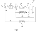
- the Figure 2 illustrates determined hub bending moment M B for example according to a structure according to Figure 3 used.
- strain can also be measured, and then blade root bending moments can be determined using a weight-based calibration. This can also be performed alternatively in the acquisition block 230.
- the current speed of the wind turbine 300 is then subtracted from the thus determined target speed n S in the speed summing element 344.
- the result is the speed control deviation e n .
- This is entered into an angle determination block 346, which determines a blade angle ⁇ S to be set.
- this blade angle ⁇ S is a target value and is entered into the wind turbine 300 for the corresponding implementation for the blade adjustment.
- the wind turbine 300 is shown here only very schematically as a corresponding block, which is divided into a blade angle area B, a generator area G and the rest of the wind turbine W.
- the target angle ⁇ S thus acts on the blade area 348.
- the speed n is input into the power block 350, which determines therefrom a target power P S , which is input into the generator section 352.
- these two values namely the nominal blade angle ⁇ S and the nominal power P S , now form the input variables for the wind turbine 300 for this consideration.
- the blade angle ⁇ S which here forms the output of the angle determination block 346, can be considered as the base angle, which can be supplemented accordingly by any individual adjustments of the individual angles.
- the result of the wind turbine 300 is at least a force F, which here consists of the three individual forces F 1 , F 2 and F 3 according to the illustration of the Figure 2
- This force value F is then input into the detection device 354.
- the detection device 354 can, for example, consist of the detection block 230 and the merging block 236 according to Figure 2
- the two blocks, namely the detection block 230 and the merging block 236, can also be referred to as the detection device 238.
- this target speed into an actual speed is carried out by the control loop, which begins with the target-actual value comparison in the speed summing element 344.
- the result of this target-actual value comparison namely the speed control deviation e n , is then converted into a corresponding angle via the angle control block 346, namely initially as a target value, which is then actually converted in the blade area 348.
- a power namely a generator power
- a characteristic curve is stored in power block 350.
- power block 350 outputs a setpoint for the power, and this setpoint PS is implemented in generator section 352. If this leads to a change in power, the speed can also change, and the power is then adjusted according to the characteristic curve and thus by power block 350.
- the generator torque also decreases, which in turn can lead to an increase in speed.
- This is counteracted in the speed control, particularly by the angle determination block 346, by reducing the blade angle.
- this in turn can also lead to a change in load and thus to a change in the force magnitude F.
- the hub bending moment M B can then change accordingly, and this can lead to a change in the target speed via the torque control deviation e M and the PI control block 342.
- this structure leads to an increase in the hub bending moment, which is counteracted by first reducing the speed and then, depending on this, also adjusting the power, namely reducing it, based on a characteristic curve in the power block 350.
Landscapes
- Engineering & Computer Science (AREA)
- Mechanical Engineering (AREA)
- Sustainable Development (AREA)
- Sustainable Energy (AREA)
- Chemical & Material Sciences (AREA)
- Combustion & Propulsion (AREA)
- Life Sciences & Earth Sciences (AREA)
- General Engineering & Computer Science (AREA)
- Physics & Mathematics (AREA)
- Fluid Mechanics (AREA)
- Wind Motors (AREA)
- Control Of Eletrric Generators (AREA)
- Force Measurement Appropriate To Specific Purposes (AREA)
Claims (10)
- Procédé destiné à faire fonctionner une éolienne (200) pour produire de l'énergie électrique à partir du vent, dans lequel- l'éolienne (200) présente un rotor aérodynamique avec un moyeu de rotor et des pales de rotor (201, 202, 203) dont l'angle de pale (α) peut être ajusté et le rotor aérodynamique peut fonctionner à une vitesse de rotation variable, et- l'éolienne (200) présente un générateur couplé au rotor aérodynamique pour produire une puissance de générateur, dans lequel- le générateur peut fonctionner avec un couple de générateur variable, comprenant les étapes :- de détermination d'une grandeur de charge sur l'éolienne (200), qui indique une charge de l'éolienne (200) par le vent,- de passage dans un mode de charge lorsque la taille de la charge atteint ou dépasse une valeur limite de charge, et- de réduction de la vitesse de rotation et/ou de la puissance de générateur dans le mode de charge, dans lequel le procédé est caractérisé par les étapes- de détection des valeurs de mesure par des jauges de contrainte (221, 222, 223) qui sont disposées sur toutes les racines de pale (211-213) des pales de rotor, sous forme de grandeurs de force vectorielles (F1 -F3),- de calcul d'une composante vectorielle de couple de flexion de moyeu (MB1, MB2, MB3) pour chaque pale de rotor,- d'addition vectorielle des composantes vectorielles de couple de flexion de moyeu (MB1, MB2, MB3) en un couple de flexion de moyeu commun (MB) pour former la grandeur de charge.
- Procédé selon la revendication 1, caractérisé en ce que la détermination de la grandeur de charge au moyen d'un algorithme d'estimation systémique s'effectue sur la base d'au moins une mesure représentative de la charge, sur la base d'une mesure d'allongement sur le moyeu de rotor.
- Procédé selon la revendication 1 ou 2, caractérisé en ce que la valeur limite de charge est fixée en fonction d'une grandeur de charge détectée comme charge de base lors d'un fonctionnement normal avec un vent nominal prédominant, en particulier de telle sorte que la valeur limite de charge est fixée au moins sur une valeur double de la charge de base.
- Procédé selon l'une quelconque des revendications précédentes, caractérisé en ce que la vitesse de rotation et/ou la puissance de générateur sont réduites en fonction de la charge détectée de telle sorte que- la grandeur de charge ne dépasse pas la valeur limite de charge et/ou- la grandeur de charge est régulée par la réduction de la vitesse de rotation et de la puissance de générateur sur la limite de charge comme valeur de consigne ou une valeur inférieure à la valeur de consigne.
- Procédé selon l'une quelconque des revendications précédentes, caractérisé en ce que la vitesse de rotation et la puissance de générateur sont réduites de telle manière que- la grandeur de charge ne dépasse pas la valeur limite de charge,- les pales de rotor (201, 202, 203) sont ajustées respectivement dans leur angle de pale (α) dans la direction opposée au vent,- le couple de générateur ne dépasse pas un couple nominal de générateur et- le couple de générateur est réduit à mesure que la vitesse du vent augmente.
- Procédé selon l'une quelconque des revendications précédentes, caractérisé en ce que- la vitesse de rotation est réduite en fonction de la grandeur de charge déterminée et- la puissance de générateur est réduite en fonction d'une courbe caractéristique de vitesse de rotation-puissance pour le fonctionnement en charge et dans lequel- ladite courbe caractéristique de vitesse de rotation-puissance pour le fonctionnement en charge diffère d'une courbe caractéristique de vitesse de rotation-puissance pour le fonctionnement en charge partielle, dans lequel le vent est si faible qu'une puissance nominale de générateur ne peut pas être atteinte.
- Procédé selon la revendication 6, caractérisé en ce que la courbe caractéristique de vitesse de rotation-puissance pour le fonctionnement en charge présente respectivement une valeur de puissance plus élevée que celle de la courbe caractéristique de vitesse de rotation-puissance pour le fonctionnement en charge partielle, au moins dans une plage de vitesse de rotation partielle, en particulier dans une plage de vitesse de rotation de 10 % à 90 % de la vitesse de rotation nominale.
- Procédé selon l'une quelconque des revendications précédentes, caractérisé en ce que, pour l'injection de la puissance électrique de générateur- le courant électrique généré par le générateur est redressé et alimenté dans un premier circuit intermédiaire de tension continue,- le courant redressé est amené par le premier circuit intermédiaire à tension continue à un deuxième circuit intermédiaire à tension continue, dans lequel- un convertisseur élévateur est disposé entre le premier et le deuxième circuit intermédiaire à tension continue pour augmenter, le cas échéant, une première tension continue du premier circuit intermédiaire à tension continue à une deuxième tension du deuxième circuit intermédiaire à tension continue,- le courant électrique du deuxième circuit intermédiaire à tension continue est transformé par un onduleur en un courant alternatif électrique destiné à être injecté dans le réseau d'alimentation électrique, dans lequel- le convertisseur élévateur augmente la première tension continue à la deuxième tension continue uniquement pour des vitesses de rotation inférieures à une vitesse de rotation de commutation, de telle sorte que la deuxième tension continue est alors supérieure à la première tension continue et- la vitesse de rotation de commutation en charge partielle est plus élevée que dans le fonctionnement en charge.
- Éolienne (200) destinée à produire de l'énergie électrique à partir du vent, comprenant- un rotor aérodynamique avec un moyeu de rotor et des pales de rotor dont l'angle de pale (α) peut être ajusté, dans lequel le rotor aérodynamique peut fonctionner à une vitesse de rotation variable,- un générateur couplé au rotor aérodynamique, destiné à produire une puissance de générateur, dans lequel le générateur peut fonctionner avec un couple de générateur variable,- un dispositif de détection destiné à déterminer une grandeur de charge sur l'éolienne (200), qui indique une charge de l'éolienne (200) par le vent, dans lequel le dispositif de détection est préparé pour déterminer la grandeur de charge,- une jauge de contrainte (221, 222, 223) sur le moyeu de rotor pour détecter un couple de flexion de moyeu qui varie en fonction de la position du rotor (β) entre les couples de flexion de moyeu maximal et minimal,- au moins une liaison de la jauge de contrainte (221, 222, 223) et du dispositif de détection qui est prévue pour transmettre des valeurs de mesure de la jauge de contrainte au dispositif de détection,- un dispositif de commande préparé pour réduire la vitesse de rotation et/ou la puissance de générateur dans un fonctionnement en charge lorsque la grandeur de charge atteint une valeur limite de charge,
caractérisé en ce que- le dispositif de détection comprend un bloc de détection (230) et un bloc de regroupement (236),- le bloc de détection (230) détecte les valeurs de mesure des jauges de contrainte (221, 222, 223) de toutes les pales de rotor en tant que grandeurs de force vectorielles (F1 -F3) et calcule pour chaque pale de rotor une composante vectorielle de couple de flexion de moyeu (MB1, MB2, MB3) et- le bloc de regroupement (236) additionne vectoriellement les composantes vectorielles de couple de flexion de moyeu (MB1, MB2, MB3) en un couple de flexion de moyeu commun (MB), qui forme la grandeur de charge. - Éolienne (200) selon la revendication 9, caractérisée en ce qu'elle est préparée pour exécuter un procédé selon l'une quelconque des revendications 1 à 8.
Applications Claiming Priority (2)
| Application Number | Priority Date | Filing Date | Title |
|---|---|---|---|
| DE102017121563.8A DE102017121563A1 (de) | 2017-09-18 | 2017-09-18 | Windenergieanlage und Verfahren zum Betreiben einer Windenergieanlage |
| PCT/EP2018/073346 WO2019052827A1 (fr) | 2017-09-18 | 2018-08-30 | Éolienne et procédé permettant de faire fonctionner une éolienne |
Publications (3)
| Publication Number | Publication Date |
|---|---|
| EP3685036A1 EP3685036A1 (fr) | 2020-07-29 |
| EP3685036B1 true EP3685036B1 (fr) | 2025-06-25 |
| EP3685036C0 EP3685036C0 (fr) | 2025-06-25 |
Family
ID=63442647
Family Applications (1)
| Application Number | Title | Priority Date | Filing Date |
|---|---|---|---|
| EP18762289.9A Active EP3685036B1 (fr) | 2017-09-18 | 2018-08-30 | Éolienne et procédé permettant de faire fonctionner une éolienne |
Country Status (9)
| Country | Link |
|---|---|
| US (1) | US11525432B2 (fr) |
| EP (1) | EP3685036B1 (fr) |
| JP (1) | JP7130033B2 (fr) |
| KR (1) | KR102455702B1 (fr) |
| CN (1) | CN111094742B (fr) |
| CA (1) | CA3074397C (fr) |
| DE (1) | DE102017121563A1 (fr) |
| RU (1) | RU2742253C1 (fr) |
| WO (1) | WO2019052827A1 (fr) |
Families Citing this family (8)
| Publication number | Priority date | Publication date | Assignee | Title |
|---|---|---|---|---|
| DK3848575T3 (da) * | 2020-01-09 | 2026-01-12 | Nordex Energy Se & Co Kg | Fremgangsmåde til drift af en vindpark med en flerhed af vindmøller og tilsvarende vindpark |
| EP3910194A1 (fr) * | 2020-05-12 | 2021-11-17 | Siemens Gamesa Renewable Energy A/S | Agencement pour la commande d'éolienne |
| EP3961177B1 (fr) * | 2020-08-25 | 2022-06-15 | AIRBUS HELICOPTERS DEUTSCHLAND GmbH | Appareil de mesure permettant de déterminer un moment de flexion |
| EP4033090B1 (fr) * | 2021-01-22 | 2024-08-28 | Wobben Properties GmbH | Procédé de commande d'une éolienne |
| CN113704920B (zh) * | 2021-08-30 | 2024-01-16 | 上海电气风电集团股份有限公司 | 螺栓强度确定方法、系统和可读存储介质 |
| KR20240090319A (ko) * | 2021-10-07 | 2024-06-21 | 제너럴 일렉트릭 레노바블레스 에스빠냐 에스.엘.유. | 풍력 터빈을 제어하기 위한 시스템 및 방법 |
| CN114281029B (zh) * | 2021-10-29 | 2024-12-10 | 金风科技股份有限公司 | 风力发电机的数字孪生系统和方法 |
| US12359588B1 (en) | 2024-08-02 | 2025-07-15 | General Electric Company | Aircraft engine aeromechanical instability detection |
Citations (2)
| Publication number | Priority date | Publication date | Assignee | Title |
|---|---|---|---|---|
| EP1988284A1 (fr) * | 2007-05-03 | 2008-11-05 | Siemens Aktiengesellschaft | Procédé de fonctionnement d'une éolienne et une éolienne |
| EP3276164A2 (fr) * | 2016-07-28 | 2018-01-31 | General Electric Company | Système et procédé de commande d'une éolienne |
Family Cites Families (12)
| Publication number | Priority date | Publication date | Assignee | Title |
|---|---|---|---|---|
| DE19532409B4 (de) | 1995-09-01 | 2005-05-12 | Wobben, Aloys, Dipl.-Ing. | Verfahren zum Betreiben einer Windenergieanlage und eine zugehörige Windenergieanlage |
| DE102004054608B4 (de) | 2004-09-21 | 2006-06-29 | Repower Systems Ag | Verfahren zur Regelung einer Windenergieanlage und Windenergieanlage mit einem Rotor |
| US7476985B2 (en) | 2005-07-22 | 2009-01-13 | Gamesa Innovation & Technology, S.L. | Method of operating a wind turbine |
| JP4898230B2 (ja) * | 2006-01-18 | 2012-03-14 | 学校法人福岡工業大学 | 風力発電システムの運転制御方法及びその装置 |
| DE102008020154B4 (de) * | 2008-04-22 | 2011-04-28 | Repower Systems Ag | Verfahren zum Betreiben einer Windenergieanlage |
| DK201070274A (en) | 2009-10-08 | 2011-04-09 | Vestas Wind Sys As | Control method for a wind turbine |
| ES2694009T3 (es) * | 2013-12-09 | 2018-12-17 | Vestas Wind Systems A/S | Método de operación de una turbina eólica |
| DK2927486T3 (en) | 2014-03-31 | 2018-08-20 | Alstom Renovables Espana Sl | Fatigue in wind turbines |
| RU2572252C1 (ru) | 2014-07-11 | 2016-01-10 | Федеральное государственное бюджетное образовательное учреждение высшего профессионального образования "Оренбургский государственный аграрный университет" | Конструкция ветроэнергетической установки |
| EP3085955A1 (fr) * | 2015-04-20 | 2016-10-26 | Siemens Aktiengesellschaft | Procédé de contrôle du fonctionnement d'une éolienne |
| DK179069B1 (en) | 2015-09-04 | 2017-10-02 | Envision Energy Denmark Aps | A wind turbine and a method of operating a wind turbine with a rotational speed exclusion zone |
| JP6405324B2 (ja) * | 2016-01-29 | 2018-10-17 | 三菱重工業株式会社 | 風力発電装置及びその運転方法 |
-
2017
- 2017-09-18 DE DE102017121563.8A patent/DE102017121563A1/de not_active Withdrawn
-
2018
- 2018-08-30 CA CA3074397A patent/CA3074397C/fr active Active
- 2018-08-30 JP JP2020515880A patent/JP7130033B2/ja active Active
- 2018-08-30 RU RU2020113599A patent/RU2742253C1/ru active
- 2018-08-30 WO PCT/EP2018/073346 patent/WO2019052827A1/fr not_active Ceased
- 2018-08-30 EP EP18762289.9A patent/EP3685036B1/fr active Active
- 2018-08-30 US US16/645,948 patent/US11525432B2/en active Active
- 2018-08-30 CN CN201880060653.5A patent/CN111094742B/zh active Active
- 2018-08-30 KR KR1020207010541A patent/KR102455702B1/ko active Active
Patent Citations (2)
| Publication number | Priority date | Publication date | Assignee | Title |
|---|---|---|---|---|
| EP1988284A1 (fr) * | 2007-05-03 | 2008-11-05 | Siemens Aktiengesellschaft | Procédé de fonctionnement d'une éolienne et une éolienne |
| EP3276164A2 (fr) * | 2016-07-28 | 2018-01-31 | General Electric Company | Système et procédé de commande d'une éolienne |
Also Published As
| Publication number | Publication date |
|---|---|
| DE102017121563A1 (de) | 2019-03-21 |
| CN111094742B (zh) | 2023-02-10 |
| US11525432B2 (en) | 2022-12-13 |
| US20200200146A1 (en) | 2020-06-25 |
| CA3074397A1 (fr) | 2019-03-21 |
| RU2742253C1 (ru) | 2021-02-04 |
| KR20200053561A (ko) | 2020-05-18 |
| JP7130033B2 (ja) | 2022-09-02 |
| CA3074397C (fr) | 2023-10-17 |
| EP3685036A1 (fr) | 2020-07-29 |
| CN111094742A (zh) | 2020-05-01 |
| KR102455702B1 (ko) | 2022-10-18 |
| EP3685036C0 (fr) | 2025-06-25 |
| BR112020005068A2 (pt) | 2020-09-15 |
| WO2019052827A1 (fr) | 2019-03-21 |
| JP2020535343A (ja) | 2020-12-03 |
Similar Documents
| Publication | Publication Date | Title |
|---|---|---|
| EP3685036B1 (fr) | Éolienne et procédé permettant de faire fonctionner une éolienne | |
| DE102004054608B4 (de) | Verfahren zur Regelung einer Windenergieanlage und Windenergieanlage mit einem Rotor | |
| EP1132614B1 (fr) | Système de réglage pour une éolienne | |
| EP2464862B1 (fr) | Éolienne avec une réserve de puissance ajustable | |
| EP2063109B1 (fr) | Procédé de commande d'une éolienne | |
| EP2411669B1 (fr) | Procédé de fonctionnement d'un aérogénérateur | |
| EP1362183B1 (fr) | Installation d'energie eolienne | |
| EP3542056B1 (fr) | Procédé pour commander une éolienne et éolienne correspondante | |
| DE3308564A1 (de) | Windturbinenanlage | |
| WO2013041192A2 (fr) | Procédé permettant de faire fonctionner une éolienne | |
| EP3095168A1 (fr) | Procédé et dispositif de réglage et/ou commande pour faire fonctionner une éolienne et/ou un parc éolien et éolienne et parc éolien correspondants | |
| WO2019134793A1 (fr) | Fonctionnement d'une éolienne en cas de tempête | |
| WO2019197680A1 (fr) | Éolienne, parc éolien et procédé de réglage d'une éolienne et d'un parc éolien | |
| EP2961981B1 (fr) | Éoliennes à mise à disposition améliorée de la réserve de puissance | |
| EP3555461B1 (fr) | Procédé pour faire fonctionner un aérogénérateur ainsi que dispositif pour commander et/ou réguler un aérogénérateur et aérogénérateur correspondant comprenant un rotor et un générateur entraîné par le biais du rotor pour générer une puissance électrique | |
| EP2914844A2 (fr) | Procédé pour faire fonctionner une éolienne, éolienne et dispositif de commande pour une éolienne | |
| EP3685037B1 (fr) | Procédé pour une éolienne en régime de secours, commande et éolienne | |
| EP2948678B1 (fr) | Procédé de réglage azimutal d'une éolienne, système de réglage azimutal et éolienne | |
| DE102018100727A1 (de) | Verfahren zum Steuern einer Windenergieanlage und Windenergieanlage | |
| WO2012007111A2 (fr) | Procédé et dispositif pour produire un signal de correction d'angle d'attaque pour une pale de rotor prédéterminée d'une éolienne | |
| EP3495656B1 (fr) | Procédé de détermination de la dynamique de charge d'une éolienne | |
| EP3555462A1 (fr) | Procédé permettant de commander une éolienne | |
| DE102018130636A1 (de) | Verfahren zum Betreiben einer Windenergieanlage | |
| DE102012024272A1 (de) | Verfahren und Vorrichtung zum Verringern eines Rotors einer Windenergieanlage belastenden Nickmoments | |
| EP3891384B1 (fr) | Procédé servant à faire fonctionner au moins une éolienne, ainsi que dispositif associé |
Legal Events
| Date | Code | Title | Description |
|---|---|---|---|
| STAA | Information on the status of an ep patent application or granted ep patent |
Free format text: STATUS: UNKNOWN |
|
| STAA | Information on the status of an ep patent application or granted ep patent |
Free format text: STATUS: THE INTERNATIONAL PUBLICATION HAS BEEN MADE |
|
| PUAI | Public reference made under article 153(3) epc to a published international application that has entered the european phase |
Free format text: ORIGINAL CODE: 0009012 |
|
| STAA | Information on the status of an ep patent application or granted ep patent |
Free format text: STATUS: REQUEST FOR EXAMINATION WAS MADE |
|
| 17P | Request for examination filed |
Effective date: 20200324 |
|
| AK | Designated contracting states |
Kind code of ref document: A1 Designated state(s): AL AT BE BG CH CY CZ DE DK EE ES FI FR GB GR HR HU IE IS IT LI LT LU LV MC MK MT NL NO PL PT RO RS SE SI SK SM TR |
|
| AX | Request for extension of the european patent |
Extension state: BA ME |
|
| DAV | Request for validation of the european patent (deleted) | ||
| DAX | Request for extension of the european patent (deleted) | ||
| STAA | Information on the status of an ep patent application or granted ep patent |
Free format text: STATUS: EXAMINATION IS IN PROGRESS |
|
| 17Q | First examination report despatched |
Effective date: 20220411 |
|
| GRAP | Despatch of communication of intention to grant a patent |
Free format text: ORIGINAL CODE: EPIDOSNIGR1 |
|
| STAA | Information on the status of an ep patent application or granted ep patent |
Free format text: STATUS: GRANT OF PATENT IS INTENDED |
|
| INTG | Intention to grant announced |
Effective date: 20250122 |
|
| GRAS | Grant fee paid |
Free format text: ORIGINAL CODE: EPIDOSNIGR3 |
|
| GRAA | (expected) grant |
Free format text: ORIGINAL CODE: 0009210 |
|
| STAA | Information on the status of an ep patent application or granted ep patent |
Free format text: STATUS: THE PATENT HAS BEEN GRANTED |
|
| AK | Designated contracting states |
Kind code of ref document: B1 Designated state(s): AL AT BE BG CH CY CZ DE DK EE ES FI FR GB GR HR HU IE IS IT LI LT LU LV MC MK MT NL NO PL PT RO RS SE SI SK SM TR |
|
| REG | Reference to a national code |
Ref country code: GB Ref legal event code: FG4D Free format text: NOT ENGLISH |
|
| REG | Reference to a national code |
Ref country code: CH Ref legal event code: EP |
|
| REG | Reference to a national code |
Ref country code: CH Ref legal event code: EP |
|
| REG | Reference to a national code |
Ref country code: IE Ref legal event code: FG4D Free format text: LANGUAGE OF EP DOCUMENT: GERMAN |
|
| U01 | Request for unitary effect filed |
Effective date: 20250625 |
|
| U07 | Unitary effect registered |
Designated state(s): AT BE BG DE DK EE FI FR IT LT LU LV MT NL PT RO SE SI Effective date: 20250701 |
|
| U20 | Renewal fee for the european patent with unitary effect paid |
Year of fee payment: 8 Effective date: 20250731 |
|
| PG25 | Lapsed in a contracting state [announced via postgrant information from national office to epo] |
Ref country code: NO Free format text: LAPSE BECAUSE OF FAILURE TO SUBMIT A TRANSLATION OF THE DESCRIPTION OR TO PAY THE FEE WITHIN THE PRESCRIBED TIME-LIMIT Effective date: 20250925 Ref country code: GR Free format text: LAPSE BECAUSE OF FAILURE TO SUBMIT A TRANSLATION OF THE DESCRIPTION OR TO PAY THE FEE WITHIN THE PRESCRIBED TIME-LIMIT Effective date: 20250926 |
|
| PGFP | Annual fee paid to national office [announced via postgrant information from national office to epo] |
Ref country code: GB Payment date: 20250822 Year of fee payment: 8 |
|
| PG25 | Lapsed in a contracting state [announced via postgrant information from national office to epo] |
Ref country code: HR Free format text: LAPSE BECAUSE OF FAILURE TO SUBMIT A TRANSLATION OF THE DESCRIPTION OR TO PAY THE FEE WITHIN THE PRESCRIBED TIME-LIMIT Effective date: 20250625 |
|
| PG25 | Lapsed in a contracting state [announced via postgrant information from national office to epo] |
Ref country code: RS Free format text: LAPSE BECAUSE OF FAILURE TO SUBMIT A TRANSLATION OF THE DESCRIPTION OR TO PAY THE FEE WITHIN THE PRESCRIBED TIME-LIMIT Effective date: 20250925 |
|
| PG25 | Lapsed in a contracting state [announced via postgrant information from national office to epo] |
Ref country code: IS Free format text: LAPSE BECAUSE OF FAILURE TO SUBMIT A TRANSLATION OF THE DESCRIPTION OR TO PAY THE FEE WITHIN THE PRESCRIBED TIME-LIMIT Effective date: 20251025 |
|
| PG25 | Lapsed in a contracting state [announced via postgrant information from national office to epo] |
Ref country code: SM Free format text: LAPSE BECAUSE OF FAILURE TO SUBMIT A TRANSLATION OF THE DESCRIPTION OR TO PAY THE FEE WITHIN THE PRESCRIBED TIME-LIMIT Effective date: 20250625 |
|
| PG25 | Lapsed in a contracting state [announced via postgrant information from national office to epo] |
Ref country code: CZ Free format text: LAPSE BECAUSE OF FAILURE TO SUBMIT A TRANSLATION OF THE DESCRIPTION OR TO PAY THE FEE WITHIN THE PRESCRIBED TIME-LIMIT Effective date: 20250625 |
|
| PG25 | Lapsed in a contracting state [announced via postgrant information from national office to epo] |
Ref country code: PL Free format text: LAPSE BECAUSE OF FAILURE TO SUBMIT A TRANSLATION OF THE DESCRIPTION OR TO PAY THE FEE WITHIN THE PRESCRIBED TIME-LIMIT Effective date: 20250625 |
|
| PG25 | Lapsed in a contracting state [announced via postgrant information from national office to epo] |
Ref country code: SK Free format text: LAPSE BECAUSE OF FAILURE TO SUBMIT A TRANSLATION OF THE DESCRIPTION OR TO PAY THE FEE WITHIN THE PRESCRIBED TIME-LIMIT Effective date: 20250625 |
|
| PG25 | Lapsed in a contracting state [announced via postgrant information from national office to epo] |
Ref country code: ES Free format text: LAPSE BECAUSE OF FAILURE TO SUBMIT A TRANSLATION OF THE DESCRIPTION OR TO PAY THE FEE WITHIN THE PRESCRIBED TIME-LIMIT Effective date: 20250625 |
|
| REG | Reference to a national code |
Ref country code: CH Ref legal event code: H13 Free format text: ST27 STATUS EVENT CODE: U-0-0-H10-H13 (AS PROVIDED BY THE NATIONAL OFFICE) Effective date: 20260324 |
|
| PG25 | Lapsed in a contracting state [announced via postgrant information from national office to epo] |
Ref country code: MC Free format text: LAPSE BECAUSE OF FAILURE TO SUBMIT A TRANSLATION OF THE DESCRIPTION OR TO PAY THE FEE WITHIN THE PRESCRIBED TIME-LIMIT Effective date: 20250625 |